EP2353778A2 - Cartouche à étages - Google Patents
Cartouche à étages Download PDFInfo
- Publication number
- EP2353778A2 EP2353778A2 EP11152461A EP11152461A EP2353778A2 EP 2353778 A2 EP2353778 A2 EP 2353778A2 EP 11152461 A EP11152461 A EP 11152461A EP 11152461 A EP11152461 A EP 11152461A EP 2353778 A2 EP2353778 A2 EP 2353778A2
- Authority
- EP
- European Patent Office
- Prior art keywords
- shelf
- receiving
- receiving device
- magazine according
- tool
- Prior art date
- Legal status (The legal status is an assumption and is not a legal conclusion. Google has not performed a legal analysis and makes no representation as to the accuracy of the status listed.)
- Granted
Links
Images


Classifications
-
- B—PERFORMING OPERATIONS; TRANSPORTING
- B23—MACHINE TOOLS; METAL-WORKING NOT OTHERWISE PROVIDED FOR
- B23Q—DETAILS, COMPONENTS, OR ACCESSORIES FOR MACHINE TOOLS, e.g. ARRANGEMENTS FOR COPYING OR CONTROLLING; MACHINE TOOLS IN GENERAL CHARACTERISED BY THE CONSTRUCTION OF PARTICULAR DETAILS OR COMPONENTS; COMBINATIONS OR ASSOCIATIONS OF METAL-WORKING MACHINES, NOT DIRECTED TO A PARTICULAR RESULT
- B23Q3/00—Devices holding, supporting, or positioning work or tools, of a kind normally removable from the machine
- B23Q3/155—Arrangements for automatic insertion or removal of tools, e.g. combined with manual handling
- B23Q3/1552—Arrangements for automatic insertion or removal of tools, e.g. combined with manual handling parts of devices for automatically inserting or removing tools
- B23Q3/15526—Storage devices; Drive mechanisms therefor
- B23Q3/15536—Non-rotary fixed racks
-
- B—PERFORMING OPERATIONS; TRANSPORTING
- B23—MACHINE TOOLS; METAL-WORKING NOT OTHERWISE PROVIDED FOR
- B23Q—DETAILS, COMPONENTS, OR ACCESSORIES FOR MACHINE TOOLS, e.g. ARRANGEMENTS FOR COPYING OR CONTROLLING; MACHINE TOOLS IN GENERAL CHARACTERISED BY THE CONSTRUCTION OF PARTICULAR DETAILS OR COMPONENTS; COMBINATIONS OR ASSOCIATIONS OF METAL-WORKING MACHINES, NOT DIRECTED TO A PARTICULAR RESULT
- B23Q3/00—Devices holding, supporting, or positioning work or tools, of a kind normally removable from the machine
- B23Q3/155—Arrangements for automatic insertion or removal of tools, e.g. combined with manual handling
- B23Q3/1552—Arrangements for automatic insertion or removal of tools, e.g. combined with manual handling parts of devices for automatically inserting or removing tools
- B23Q3/15526—Storage devices; Drive mechanisms therefor
- B23Q3/15539—Plural magazines, e.g. involving tool transfer from one magazine to another
-
- B—PERFORMING OPERATIONS; TRANSPORTING
- B23—MACHINE TOOLS; METAL-WORKING NOT OTHERWISE PROVIDED FOR
- B23Q—DETAILS, COMPONENTS, OR ACCESSORIES FOR MACHINE TOOLS, e.g. ARRANGEMENTS FOR COPYING OR CONTROLLING; MACHINE TOOLS IN GENERAL CHARACTERISED BY THE CONSTRUCTION OF PARTICULAR DETAILS OR COMPONENTS; COMBINATIONS OR ASSOCIATIONS OF METAL-WORKING MACHINES, NOT DIRECTED TO A PARTICULAR RESULT
- B23Q7/00—Arrangements for handling work specially combined with or arranged in, or specially adapted for use in connection with, machine tools, e.g. for conveying, loading, positioning, discharging, sorting
- B23Q7/005—Lifting devices
-
- B—PERFORMING OPERATIONS; TRANSPORTING
- B65—CONVEYING; PACKING; STORING; HANDLING THIN OR FILAMENTARY MATERIAL
- B65G—TRANSPORT OR STORAGE DEVICES, e.g. CONVEYORS FOR LOADING OR TIPPING, SHOP CONVEYOR SYSTEMS OR PNEUMATIC TUBE CONVEYORS
- B65G65/00—Loading or unloading
-
- Y—GENERAL TAGGING OF NEW TECHNOLOGICAL DEVELOPMENTS; GENERAL TAGGING OF CROSS-SECTIONAL TECHNOLOGIES SPANNING OVER SEVERAL SECTIONS OF THE IPC; TECHNICAL SUBJECTS COVERED BY FORMER USPC CROSS-REFERENCE ART COLLECTIONS [XRACs] AND DIGESTS
- Y10—TECHNICAL SUBJECTS COVERED BY FORMER USPC
- Y10T—TECHNICAL SUBJECTS COVERED BY FORMER US CLASSIFICATION
- Y10T483/00—Tool changing
- Y10T483/16—Tool changing with means to transfer work
-
- Y—GENERAL TAGGING OF NEW TECHNOLOGICAL DEVELOPMENTS; GENERAL TAGGING OF CROSS-SECTIONAL TECHNOLOGIES SPANNING OVER SEVERAL SECTIONS OF THE IPC; TECHNICAL SUBJECTS COVERED BY FORMER USPC CROSS-REFERENCE ART COLLECTIONS [XRACs] AND DIGESTS
- Y10—TECHNICAL SUBJECTS COVERED BY FORMER USPC
- Y10T—TECHNICAL SUBJECTS COVERED BY FORMER US CLASSIFICATION
- Y10T483/00—Tool changing
- Y10T483/18—Tool transfer to or from matrix
- Y10T483/1845—Plural matrices
Definitions
- shelf magazines are known in the art. Shelf magazines should be able to accommodate as wide a variety of tools or similar objects in large numbers and ready to keep them so that they can be removed from the shelf magazine and used accordingly.
- a shelf magazine must be able to accommodate many sometimes very different tools or objects and on the other hand, these relatively quickly to the demanders to provide.
- the placement and removal of tools / objects in the shelf magazine and out of this has been solved in various ways in the prior art.
- One problem with this is in the prior art that, because of the different sizes and shapes of the tools / objects, the loaders / unloaders must be constructed to suit the handling of the various sizes / shapes. Therefore, to have a great deal of flexibility in terms of manageability as many sizes / shapes, is a corresponding footprint for the Feeding devices / removal devices on shelf magazine needed.
- the object of the present invention is to enable the space required for the loading / unloading of tools / objects on a rack magazine.
- a tool / object is securely stored on the receiving device.
- the recording / delivery by the transfer unit is easy.
- the transfer paths between the lifting unit and the respective shelf, and between the lifting unit and transfer unit are short, which reduces the space required for the overall system even more.
- the shelf module is extensible in a simple manner, so that by simple measures a large number of tools / objects can be used.
- entire rack modules can be replaced quickly. The set-up time is reduced thereby advantageous.
- the shelf magazine with the features of claim 11 ensures that selected objects for a work machine are available quickly.
- the present invention offers a number of advantages.
- an optimal packing density is achieved for a shelf magazine by appropriate design of the shelf modules.
- the shelf magazine is easily expandable by a second slot for another mobile Shelf module and / or stacked by stacking the shelf modules.
- a multiple use of existing feed movements is possible (for example, the insertion and removal of the tool holder on the tool cone can be done with the existing final drive of the lifting unit).
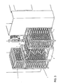
- FIG. 1 shows a schematic perspective view of a shelf magazine according to the present invention, wherein in FIG. 1 the gripping arm of a transfer unit grips a tool quiver located in a buffer.
- FIG. 1 can be removed, the shelf magazine of the present invention, a movable shelf module 1, a plurality of receiving devices 2 for receiving tools, a transfer unit 3, which passes the tools for the purpose of intermediate storage or application, and a lifting unit 4.
- the shelf module 1 is frame-like constructed as a shelf and has shelves 1a, which are formed as a simple L-shaped rails. These L-shaped rails run in such a way that a receiving device 2 described below can run displaceably on these rails in the direction of the carriage.
- FIG. 1 is apparent.
- the L-shaped rails in the respective shelf 1a are parallel to each other as in the Figures shown arranged so that the respective lower legs of the L-shape to each other.
- the vertical distance of the L-shaped rails and thus the shelves 1a in the shelf module 1 to each other, ie vertical height of each shelf, is selected according to the stored in the shelf module 1 tool. That is, a relatively large tool requires a relatively large distance of the shelves 1a in the vertical direction, whereas a relatively small tool allows a relatively short distance in the vertical direction of the shelves 1a.
- the shelf module 1 is mobile and can by means of a in FIG. 1 shown lift truck 11 are moved with, for example, electric drive. In this case, the lift truck 11 moves with its Hubwagengabeln 12 under the shelf module 1 and raises the shelf module 1 at. In order to enable a precise parking of the shelf module 1, suitable positioning aids such as pins or baffles may be provided on the floor (these are not shown).
- the shelf module 1 is expandable so that on the shelf module 1 at the top support means (not shown) are provided which allow stacking of another shelf module 1 on the shelf module 1, so that a plurality of shelf modules 1 can be positioned one above the other.
- a shelf module 1 is shown on the right side, on which no other shelf module is stacked.
- a shelf module 1 is shown, on the upper side of an additional shelf module 1 is arranged.
- the stacked shelf modules (such as on the left side of FIG. 1 ) may be the same or different Keep tools and thus have a mutually equal vertical distance of the shelves 1a or a different vertical distance of the shelves 1a.
- the respective lower shelf modules 1 may have Abstellfbiee, whereas the stacked on the top of the lower shelf modules 1 shelf modules 1 need not necessarily Abstellfbiee but may have appropriate integration facilities that allow a secure stacking. It is also possible to stack three or more shelf modules 1 one above the other.
- a receiving device 2 is arranged in each case, which serves to accommodate tools W.
- a receiving device 2 is provided in each shelf 1a .
- Each receiving device 2 is movable in the direction of the carriage relative to the associated shelf 1a along its L-shaped rails.
- Each receiving device 2 has tool receiving constructions, wherein, depending on the size of the tool, a receiving device 2 may have a single tool receiving structure or a plurality of tool receiving constructions. In the case of particularly large tools, therefore, the receiving device 2 has only one tool receiving structure, while with a smaller size of the tools, a receiving device 2 of the present invention can have several tool receiving constructions arranged next to one another. In the example of FIG.
- the receiving device 1 has the receiving device 2, which in the shelf module 1 on the right side of the representation of FIG. 1 is applied, eight juxtaposed tool receiving constructions on.
- the receiving device 2 has a longitudinal extent in (as in FIG. 1 shown) rectangular shape, with two opposite cross struts of this rectangular shape (in FIG. 1 the front and the rear cross member) have running surfaces on their undersides. These treads run on the L-shaped rails of the shelves 1a.
- each tool receiving structure has a groove shape.
- This groove shape is adapted to the shape and size of the respective tool to be deposited in it. Therefore, in the present invention, receptacles 2 with long groove shape for longer tools and short groove shape for shorter tools are conceivable.
- tool receiving structures are applicable in a stepped form, which allow safe storage of the respective tool stored therein, taking into account the contour of the respective tool (in the construction of the tool receiving structure). For the application of particularly heavy tools, the receiving device to increase the stabilization cross braces have.
- a transport lock is provided, which prevents the slipping out of the receiving devices 2 during transport (due to inclination, lateral impulses, etc.).
- the present invention comprises the lifting unit 4.
- This lifting unit 4 is preferably stationary and consists of a hinge construction with a receiving table 41 at the top of the lifting unit 4 and a drive.
- the drive provides for extending and retracting the receiving table 41 in the vertical direction.
- the shape of the Take-up table 41 at the top of the lifting unit 4 is adapted to receive a receiving device 2.
- the lifting unit 4 is extended / retracted so that its receiving table 41 is aligned with the corresponding receiving device 2 in the corresponding shelf 1a.
- the receiving table 41 of the lifting unit 4 therefore has a rectangular shape in the present embodiment, which corresponds to the rectangular shape of the receiving device 2.
- the receiving table 41 of the lifting unit 4 has on its upper side receiving surfaces, which are formed so that respective running surfaces, which are formed on the underside of the receiving device 2 as described above, can run.
- each receiving device 2 in the shelf 1a and on the running surfaces of the receiving table 41 of the lifting unit 4 are moved.
- the receiving device 2 is thereby moved by a drive which is assigned to the lifting unit 4. It makes sense that the drive can operate the modules on both sides of the lifting unit 4. This ensures that the individual shelf modules can be performed very easily. In special cases, however, it is also conceivable that the drive is also assigned to the module.
- the receiving table 41 of the lifting unit 4 has boundary walls between which the receiving device 2 can run. More specifically, the boundary walls of the take-up table 41 of the elevation unit extend adjacent to the upper treads of the take-up table 41 on the outside thereof (in FIG Fig. 1 the front and the rear side), so that on the upper running surfaces of the receiving table 41 daringly moving receiving device 2 runs between these boundary walls.
- the lifting unit 4 itself can be designed in various ways.
- the lifting unit 4 uses the Zieharmonika bin by means of articulated construction.
- Other types of construction may be used as long as extension and retraction of the take-up table 41 in the vertical direction and stopping of the take-up table 41 at transfer positions aligned with the respective shelf 1a are possible.
- the present invention further comprises the transfer unit 3.
- the transfer unit 3 serves to remove a tool W which is located on the receiving device 2 arranged on the upper side of the lifting unit 4 and to deposit it at a storage location, or to remove it from the storage location and to deposit it on the receiving device 2.
- the transfer unit 3 of the present embodiment may be provided, for example, with a tool changer as described in the patent DE 103 54 442 is described.
- a tool changer has a tool storage location in a vertically displaceable buffer for a tool which is removed from a gripper gripping the tool and transferred to a machine tool.
- the tool storage location in the buffer is designed as a holder which receives a tool holder (pot), in which the tool is seated. In this case, the tool is taken together with the tool quiver from the cache and passed.
- the transfer unit 3 of the present embodiment may have as the storage location the vertically displaceable buffer 33, as shown in FIG. 1 is shown.
- a tool holder 32 is a tool holder pot for receiving a tool W.
- Each tool holder 32 has an inner shape such as an inner cone corresponding to a cone shape formed on the tool.
- the tool in turn has the correspondingly formed outer cone, by means of which it can be used in the machine tool (in a spindle or another counterpart).
- the transfer unit 3 has a gripping arm 31.
- the gripper arm 31 is constructed as a hinge construction and can both on the respective receiving groove of the latch 33 (see Fig. 1 and Fig. 2 ) as well as the respective tools W on the receiving table 41 located on the receiving device 2 access when the receiving table 41 is arranged in the vertical position, which allows a transfer from receiving table 41 to gripping arm 31.
- the gripping arm 31, in the position in which it is maximally stretched, can grasp the tool W in the receiving form on the receiving table 41 farthest from the transfer unit 3, as shown in FIG Fig. 3 and Fig. 4 is shown.
- the gripping arm 31 can grasp a tool holder 32 together with the tool W located therein, and transfer both as one unit to the buffer 33 and deposit them there in the respective receiving groove.
- the lifting unit 4 then moves on or off in such a way that its receiving table 41 is aligned with the shelf 1a, the receiving device 2 of which is to transfer a tool W into the transfer unit 3.
- the running surfaces are aligned at the top of the receiving table 41 of the lifting unit 4 to the running surfaces of the shelf 1a (L-shaped rails), that is, they form corresponding extensions to each other.
- the receiving device 2 is pushed from the shelf 1a to the receiving table 41 of the lifting unit 4, wherein the receiving device 2 is guided by the boundary walls on the receiving table 41 of the lifting unit 4.
- the receiving device 2 has arrived at the movement stopper position on the receiving table 41 of the lifting unit 4, their horizontal running movement ends.
- the receiving table 41 of the lifting unit 4 is moved to the transfer position at which the gripper arm 31 receives the tool W by means of a tool quiver 32.
- the equipped with the tool holder 32 gripper arm 31 of the transfer unit 3 to the tool W, which is to be removed from the receiving device 2, extended, as shown in the FIGS. 1 and 2 is shown.
- tool holder 32 receives the tool W, for example, by a horizontal movement of the lifting unit in the tool longitudinal axis.
- the same drive as for retracting the receiving device 2 can also be used for this movement. If, in any case, an axial movement should be necessary for subsequent operations, this movement could also be carried out by a downstream component (transfer unit, robot, etc.).
- the gripper arm 31 pivots to the buffer 33 in such a way that the tool quiver, in which the tool W received now sits, is deposited in a receiving groove of the buffer 33, as shown in FIGS Figures 3 and 4 is shown.
- the lifting unit 4 can be lowered. Subsequently, the stored in the buffer 33 tool W can be used by the working machine 50.
- the procedure outlined above can also be carried out in the opposite manner, that is to say that a tool can be removed from the buffer 33 by means of gripping arm 31 and tool holder 32 and positioned on a receiving device 2 which has been arranged on the receiving table 41 of the lifting unit 4.
- FIG. 5 shows a further schematic perspective view of the shelf magazine according to the invention, in which the Working position of Fig. 1 and Fig. 2 from a different angle in order to facilitate the understanding of the invention.
- the shelf module 1 is mobile.
- the invention is also applicable to the case where at least one shelf module is fixed.
- the entire principle is theoretically conceivable rotated by 90 ° (according to the principle of a pharmacist's cabinet), wherein the shelf module a plurality of juxtaposed shelves are available.
- the shelf module 1 is conveyed by an electric pallet truck 11.
- the lift truck 11 can also be driven otherwise.
- the shelf module 1 has its own drive and is provided with wheels.
- the rack module 1 has wheels and can be moved by means of external drive (for example, even manually).
- the wheels should then identify a locking mechanism to prevent relative movement of the parked shelf module to the lifting unit.
- the lifting unit is anchored stationary on the ground.
- the lifting unit can also be anchored to the machine frame of the machine.
- the gripping arm of the transfer unit 3 transfers the tool W to a buffer store 33.
- the transfer unit 3 can also transfer a tool W directly to a tool changer.
- the transfer unit 3 can also transfer a tool W directly to a work machine 50.
- the tool receiving structures of the respective receiving means 2 has a groove shape which is adapted to the shape and size of the respective tool to be deposited in it.
- the inclusion of the objects is not only limited to the groove shape (gripper groove), there are also other possibilities conceivable (channel-shaped storage, etc.). It is also conceivable that the recording takes place without special shape, so that e.g. a workpiece blank with flat surfaces simply placed on the insert and then picked up via a suitable gripping system possibly with additional movements in the gripper arm and then transferred directly or via a buffer in the machine.
- the stored object to be transferred and used by the work machine 50 is a tool W used in a machine tool 50.
- the object may be an electrode used in an erosion machine 50.
- the object can be a workpiece. Further possible uses are conceivable because the principle underlying the present invention is not limited to the type of object. The invention is thus applicable to any suitable objects to be stored, transferred and used at a place of use.
Applications Claiming Priority (1)
| Application Number | Priority Date | Filing Date | Title |
|---|---|---|---|
| DE102010001724A DE102010001724B4 (de) | 2010-02-09 | 2010-02-09 | Regalmagazin |
Publications (4)
| Publication Number | Publication Date |
|---|---|
| EP2353778A2 true EP2353778A2 (fr) | 2011-08-10 |
| EP2353778A3 EP2353778A3 (fr) | 2011-10-26 |
| EP2353778B1 EP2353778B1 (fr) | 2014-03-12 |
| EP2353778B8 EP2353778B8 (fr) | 2014-06-25 |
Family
ID=44023040
Family Applications (1)
| Application Number | Title | Priority Date | Filing Date |
|---|---|---|---|
| EP11152461.7A Not-in-force EP2353778B8 (fr) | 2010-02-09 | 2011-01-28 | Cartouche à étages |
Country Status (6)
| Country | Link |
|---|---|
| US (1) | US20110194917A1 (fr) |
| EP (1) | EP2353778B8 (fr) |
| JP (1) | JP2011178563A (fr) |
| CN (1) | CN102189538A (fr) |
| DE (1) | DE102010001724B4 (fr) |
| ES (1) | ES2461993T3 (fr) |
Cited By (3)
| Publication number | Priority date | Publication date | Assignee | Title |
|---|---|---|---|---|
| EP3520956A1 (fr) * | 2018-01-30 | 2019-08-07 | DECKEL MAHO Pfronten GmbH | Dispositif d'alimentation pour un magasin d'outils d'un machine-outil ainsi que procédé de changement d'un outil sur un magasin d'outil |
| CN111123189A (zh) * | 2019-12-25 | 2020-05-08 | 国网北京市电力公司 | 计量箱温升试验装置 |
| DE102020115619A1 (de) | 2020-06-12 | 2021-12-16 | Dematic Gmbh | Warenlager- und Auftragserfüllungssystem |
Families Citing this family (23)
| Publication number | Priority date | Publication date | Assignee | Title |
|---|---|---|---|---|
| DE102011076595A1 (de) * | 2011-05-27 | 2012-11-29 | Homag Holzbearbeitungssysteme Gmbh | Bearbeitungsvorrichtung |
| JP5733580B2 (ja) * | 2012-11-13 | 2015-06-10 | 株式会社ダイフク | 物品搬送装置及びそれを備えた物品収納設備 |
| CN104210797A (zh) * | 2013-06-03 | 2014-12-17 | 昆山飞达磨具制造有限公司 | 砂轮片储存柜 |
| DE102013106427B4 (de) | 2013-06-19 | 2021-02-25 | Klaus Hofmann | Verfahren zum Bereitstellen von Werkmitteln und Ladesystem zur Durchführung des Verfahrens |
| CN104477550A (zh) * | 2014-12-10 | 2015-04-01 | 马瑞利汽车零部件(芜湖)有限公司 | 一种箱体辅助运输架 |
| CN104647327B (zh) * | 2015-02-10 | 2017-02-01 | 安徽安凯汽车股份有限公司 | 一种客车用阀类组合存储、转运工装 |
| DE102015116729A1 (de) | 2015-10-01 | 2017-04-06 | Mikromat Gmbh | Verfahren und Vorrichtung zur Prozessgestaltung bei einer Maschinenbeschickung und/oder Maschinenentnahme |
| CN106041846A (zh) * | 2016-07-26 | 2016-10-26 | 苏州科明纺织有限公司 | 一种多层纺织辊架 |
| US10647531B2 (en) * | 2016-11-08 | 2020-05-12 | Greenheart Farms, Inc. | Independently automated loading system for unitized loads into a covered multi-level transporter |
| WO2018129738A1 (fr) * | 2017-01-16 | 2018-07-19 | 浙江国自机器人技术有限公司 | Robot porte-contenants |
| FR3054465B1 (fr) * | 2017-02-17 | 2024-02-02 | Jerome Prevost | Magasin universel pour l'alimentation en ebauches et la reception des pieces usinees d'une machine-outil. |
| CN106829297B (zh) * | 2017-04-16 | 2018-07-31 | 嘉峪关市三川物流有限公司 | 一种摩天轮式智能仓储装置 |
| DE202017106597U1 (de) * | 2017-10-30 | 2019-01-31 | Aberu Gmbh | Vorrichtung zum Bewegen von stapelbaren Ladungsträgern |
| DE102018119280A1 (de) | 2018-08-08 | 2020-02-13 | Homag Bohrsysteme Gmbh | Werkstückhandhabungsvorrichtung und Verfahren zur Stapelverarbeitung von plattenförmigen Werkstücken |
| US20220000280A1 (en) * | 2018-11-05 | 2022-01-06 | Simon Tiwha Enterprises Pty Ltd | Apparatus for use with a display unit |
| CN110803438B (zh) * | 2019-11-03 | 2024-01-30 | 江苏诺丁金属科技有限公司 | 一种五金仓储设备 |
| CN110803437B (zh) * | 2019-11-03 | 2024-01-30 | 泰州市宇锋机械有限公司 | 一种五金放置柜 |
| CN110900278B (zh) * | 2019-12-12 | 2022-03-22 | 湖北文理学院 | 多机床刀库的换刀系统 |
| CN111251267A (zh) * | 2020-03-06 | 2020-06-09 | 中冶天工集团有限公司 | 一种用于罐体式电除尘器阳极排的存放工具及使用方法 |
| CN111392184A (zh) * | 2020-04-24 | 2020-07-10 | 惠州市东一钢结构有限公司 | 一种用于钢材放置的存储架 |
| CN111591654B (zh) * | 2020-06-09 | 2021-07-02 | 国网冀北综合能源服务有限公司 | 电力设备仓储系统 |
| CN112722557B (zh) * | 2020-12-30 | 2022-05-10 | 客来福家居股份有限公司 | 一种家具板材检测用板材放置架 |
| CN113334336B (zh) * | 2021-05-21 | 2022-11-04 | 蓝海建设集团有限公司 | 一种用于现场存放钢筋的存放结构 |
Citations (1)
| Publication number | Priority date | Publication date | Assignee | Title |
|---|---|---|---|---|
| DE10354442A1 (de) | 2003-11-21 | 2005-06-23 | Miksch Gmbh | Werkzeugwechselsystem |
Family Cites Families (24)
| Publication number | Priority date | Publication date | Assignee | Title |
|---|---|---|---|---|
| JPS59108622A (ja) * | 1982-12-08 | 1984-06-23 | Kanto Seiki Kk | 工場に於ける自動ハンドリングシステム装置 |
| JPS60131144A (ja) * | 1983-12-19 | 1985-07-12 | Toshiba Corp | ワ−ク供給装置 |
| JPH0653333B2 (ja) * | 1985-07-19 | 1994-07-20 | キヤノン株式会社 | 物品等の自動供給装置 |
| JPS63200941A (ja) * | 1987-02-13 | 1988-08-19 | Kyoritsu Seiki Kk | 数値制御複合工作機械に於けるワ−ク及び工具自動交換装置 |
| DE3715874C1 (de) * | 1987-05-01 | 1988-10-13 | Werner & Kolb Werkzeugmasch | Einrichtung zum Wechseln von Werkzeugen eines numerisch gesteuerten Bearbeitungszentrums |
| CA1317897C (fr) * | 1987-07-14 | 1993-05-18 | Henricus J. J. Bouwens | Dispositif de deplacement de supports pour appareil de positionnement et dispositif de selection pour ce dispositif de deplacement |
| JPH01124505A (ja) * | 1987-11-04 | 1989-05-17 | Nec Corp | 自動部品払い出し装置 |
| DE3824328C1 (fr) * | 1988-07-18 | 1989-12-21 | Kone-Anlagenbau Gmbh, 8900 Augsburg, De | |
| JP2575819Y2 (ja) * | 1992-01-27 | 1998-07-02 | セイレイ工業株式会社 | 回転育苗機 |
| CN1189436A (zh) * | 1997-01-28 | 1998-08-05 | 三星电子株式会社 | 托盘供给装置 |
| DE29723886U1 (de) * | 1997-04-29 | 1999-04-22 | Promot Ind Automatisierungs Sy | Handhabungssystem für Werkstücke mit Umstapelzelle für Werkstückträger |
| JP3380741B2 (ja) * | 1998-03-26 | 2003-02-24 | 住友ゴム工業株式会社 | ビード取り上げ装置 |
| JP3491557B2 (ja) * | 1999-04-22 | 2004-01-26 | 松下電器産業株式会社 | 電子部品供給用のトレイフィーダ |
| JP2001150276A (ja) * | 1999-11-24 | 2001-06-05 | Olympus Optical Co Ltd | 工作機械及び工作機械の工具管理方法 |
| JP3502047B2 (ja) * | 2001-02-01 | 2004-03-02 | 日酸Tanaka株式会社 | 切断システム |
| US6678583B2 (en) * | 2001-08-06 | 2004-01-13 | Seminet, Inc. | Robotic storage buffer system for substrate carrier pods |
| JP2004345837A (ja) * | 2003-05-26 | 2004-12-09 | Central Uni Co Ltd | 医療用格納装置 |
| JP4449363B2 (ja) * | 2003-08-08 | 2010-04-14 | 株式会社Ihi | 図書入出庫方法及び自動書庫 |
| KR101192480B1 (ko) * | 2004-04-30 | 2012-10-17 | 가부시키가이샤 유야마 세이사쿠쇼 | 트레이 배출 장치 |
| EP1607174A1 (fr) * | 2004-06-15 | 2005-12-21 | Zimmer & Kreim GmbH & Co. KG | Dispositif pour chargement et déchargement d'outils dans/d'un magasin d'outils d'une machine-outil |
| DE102005036695B4 (de) * | 2005-08-04 | 2007-07-26 | A U E Automations- Und Einstelltechnik Kassel Gmbh | Bereitstellplatz und Verfahren zum Bereitstellen von Werkstücken für eine automatisierte Bearbeitungsstation |
| JP5005046B2 (ja) * | 2008-02-22 | 2012-08-22 | 株式会社牧野フライス製作所 | 工具マガジン |
| FR2938508B1 (fr) * | 2008-11-14 | 2010-12-17 | Sidel Participations | Installation de palettisation combinee avec acces securise |
| DE102009008647A1 (de) * | 2009-02-12 | 2010-09-09 | Deckel Maho Pfronten Gmbh | System zum Wechseln und Einlegen bzw. Vorlegen von Werkzeugen an einer Werkzeugmaschine und Werkzeugmagazin zum Lagern von Werkzeugen |
-
2010
- 2010-02-09 DE DE102010001724A patent/DE102010001724B4/de not_active Expired - Fee Related
-
2011
- 2011-01-28 ES ES11152461.7T patent/ES2461993T3/es active Active
- 2011-01-28 EP EP11152461.7A patent/EP2353778B8/fr not_active Not-in-force
- 2011-02-08 US US13/023,436 patent/US20110194917A1/en not_active Abandoned
- 2011-02-08 JP JP2011024554A patent/JP2011178563A/ja active Pending
- 2011-02-09 CN CN2011100394404A patent/CN102189538A/zh active Pending
Patent Citations (1)
| Publication number | Priority date | Publication date | Assignee | Title |
|---|---|---|---|---|
| DE10354442A1 (de) | 2003-11-21 | 2005-06-23 | Miksch Gmbh | Werkzeugwechselsystem |
Cited By (4)
| Publication number | Priority date | Publication date | Assignee | Title |
|---|---|---|---|---|
| EP3520956A1 (fr) * | 2018-01-30 | 2019-08-07 | DECKEL MAHO Pfronten GmbH | Dispositif d'alimentation pour un magasin d'outils d'un machine-outil ainsi que procédé de changement d'un outil sur un magasin d'outil |
| CN111123189A (zh) * | 2019-12-25 | 2020-05-08 | 国网北京市电力公司 | 计量箱温升试验装置 |
| DE102020115619A1 (de) | 2020-06-12 | 2021-12-16 | Dematic Gmbh | Warenlager- und Auftragserfüllungssystem |
| WO2021249810A1 (fr) | 2020-06-12 | 2021-12-16 | Dematic Gmbh | Système de stockage de marchandises et d'exécution de commandes |
Also Published As
| Publication number | Publication date |
|---|---|
| JP2011178563A (ja) | 2011-09-15 |
| CN102189538A (zh) | 2011-09-21 |
| ES2461993T3 (es) | 2014-05-22 |
| EP2353778B8 (fr) | 2014-06-25 |
| EP2353778A3 (fr) | 2011-10-26 |
| DE102010001724B4 (de) | 2012-02-02 |
| US20110194917A1 (en) | 2011-08-11 |
| DE102010001724A1 (de) | 2011-08-11 |
| EP2353778B1 (fr) | 2014-03-12 |
Similar Documents
| Publication | Publication Date | Title |
|---|---|---|
| DE102010001724B4 (de) | Regalmagazin | |
| DE102013009340B4 (de) | Einrichtung und Verfahren zum Ein- und Auslagern von stapelbaren Behältern | |
| DE202016009161U1 (de) | Lagersystem | |
| EP3579987B1 (fr) | Magasin d'outils de cintrage et procédé de chargement d'une presse-plieuse | |
| DE112009001363T5 (de) | Gerät und Verfahren, die eingesetzt werden, um Pakete in einem automatisierten Lager aufzuladen, zu bewegen und abzulegen | |
| DE102005009695A1 (de) | Regallager und Verfahren zum Umlagern von Lagergut bei einem Regallager | |
| DE2021611C2 (de) | Regalförderzeug | |
| EP1818282B1 (fr) | Procédé de déstockage de marchandises au détail d'un entrepôt de marchandises au détail automatisé | |
| EP2746193B1 (fr) | Véhicule pour entrepôt, transstockeur, entrepôt et procédé correspondant | |
| WO1994007775A1 (fr) | Dispositif permettant d'inserer des porte-charges dans des rayonnages et de les en sortir | |
| AT516624B1 (de) | Werkzeugmagazin und Anordnung mit einem solchen | |
| EP3782932B1 (fr) | Dispositif de stockage par empilement | |
| EP3094576B1 (fr) | Systeme constitue d'un dispositif de rayonnage et d'un moyen de reception de charge telescopique correspondant sans reglage de largeur | |
| EP2143667A1 (fr) | Dispositif de stockage pour marchandises et procédé correspondant | |
| DE4432856C2 (de) | Aufnahmevorrichtung für Paletten | |
| DE102016004532B4 (de) | Verfahren zur Handhabung von Teile aufnehmenden, gestapelten Teileträgern innerhalb einer Automationszelle | |
| DE102017114643A1 (de) | Regalbediengerät geeignet für den Einsatz in einem Hochregallager | |
| EP0352785A1 (fr) | Dispositif de manipulation et de stockage des palettes et des objets similaires à palettes ou autres | |
| EP1862405B1 (fr) | Procédé destiné à saisir une marchandise à l'aide d'éléments de préhension dans un dispositif de stockage et de déstockage et dispositif correspondant | |
| DE202020101328U1 (de) | Vorrichtung eines Werkzeugmagazins und Werkzeugmagazin | |
| DE10140643A1 (de) | Regallagersystem | |
| EP2868600B1 (fr) | Magasin et procédé de magasinage | |
| DE102016122117B4 (de) | Karosseriebauanlage, mit einem Regalsystem, zum Bearbeiten und/oder Montieren von Karosseriebauteilen | |
| DE2914404A1 (de) | Regalbediengeraet | |
| DE2031601A1 (de) | Stapelvorrichtung |
Legal Events
| Date | Code | Title | Description |
|---|---|---|---|
| PUAI | Public reference made under article 153(3) epc to a published international application that has entered the european phase |
Free format text: ORIGINAL CODE: 0009012 |
|
| AK | Designated contracting states |
Kind code of ref document: A2 Designated state(s): AL AT BE BG CH CY CZ DE DK EE ES FI FR GB GR HR HU IE IS IT LI LT LU LV MC MK MT NL NO PL PT RO RS SE SI SK SM TR |
|
| AX | Request for extension of the european patent |
Extension state: BA ME |
|
| PUAL | Search report despatched |
Free format text: ORIGINAL CODE: 0009013 |
|
| AK | Designated contracting states |
Kind code of ref document: A3 Designated state(s): AL AT BE BG CH CY CZ DE DK EE ES FI FR GB GR HR HU IE IS IT LI LT LU LV MC MK MT NL NO PL PT RO RS SE SI SK SM TR |
|
| AX | Request for extension of the european patent |
Extension state: BA ME |
|
| RIC1 | Information provided on ipc code assigned before grant |
Ipc: B23Q 3/155 20060101AFI20110922BHEP Ipc: B23Q 7/00 20060101ALI20110922BHEP Ipc: B65G 1/10 20060101ALI20110922BHEP |
|
| 17P | Request for examination filed |
Effective date: 20111124 |
|
| 17Q | First examination report despatched |
Effective date: 20120221 |
|
| GRAP | Despatch of communication of intention to grant a patent |
Free format text: ORIGINAL CODE: EPIDOSNIGR1 |
|
| INTG | Intention to grant announced |
Effective date: 20131211 |
|
| GRAS | Grant fee paid |
Free format text: ORIGINAL CODE: EPIDOSNIGR3 |
|
| GRAA | (expected) grant |
Free format text: ORIGINAL CODE: 0009210 |
|
| AK | Designated contracting states |
Kind code of ref document: B1 Designated state(s): AL AT BE BG CH CY CZ DE DK EE ES FI FR GB GR HR HU IE IS IT LI LT LU LV MC MK MT NL NO PL PT RO RS SE SI SK SM TR |
|
| REG | Reference to a national code |
Ref country code: GB Ref legal event code: FG4D Free format text: NOT ENGLISH |
|
| REG | Reference to a national code |
Ref country code: CH Ref legal event code: EP Ref country code: CH Ref legal event code: NV Representative=s name: NOVAGRAAF INTERNATIONAL SA, CH |
|
| REG | Reference to a national code |
Ref country code: AT Ref legal event code: REF Ref document number: 655914 Country of ref document: AT Kind code of ref document: T Effective date: 20140315 |
|
| RBV | Designated contracting states (corrected) |
Designated state(s): AL AT BE BG CH CY CZ DK EE ES FI FR GB GR HR HU IE IS IT LI LT LU LV MC MK MT NL NO PL PT RO RS SE SI SK SM TR |
|
| REG | Reference to a national code |
Ref country code: IE Ref legal event code: FG4D Free format text: LANGUAGE OF EP DOCUMENT: GERMAN |
|
| REG | Reference to a national code |
Ref country code: DE Ref legal event code: R107 Ref document number: 502011002345 Country of ref document: DE Effective date: 20140508 Ref country code: DE Ref legal event code: R108 Ref document number: 502011002345 Country of ref document: DE Effective date: 20140220 |
|
| REG | Reference to a national code |
Ref country code: ES Ref legal event code: FG2A Ref document number: 2461993 Country of ref document: ES Kind code of ref document: T3 Effective date: 20140522 |
|
| REG | Reference to a national code |
Ref country code: SE Ref legal event code: TRGR |
|
| REG | Reference to a national code |
Ref country code: NL Ref legal event code: VDEP Effective date: 20140312 |
|
| PG25 | Lapsed in a contracting state [announced via postgrant information from national office to epo] |
Ref country code: LT Free format text: LAPSE BECAUSE OF FAILURE TO SUBMIT A TRANSLATION OF THE DESCRIPTION OR TO PAY THE FEE WITHIN THE PRESCRIBED TIME-LIMIT Effective date: 20140312 Ref country code: NO Free format text: LAPSE BECAUSE OF FAILURE TO SUBMIT A TRANSLATION OF THE DESCRIPTION OR TO PAY THE FEE WITHIN THE PRESCRIBED TIME-LIMIT Effective date: 20140612 |
|
| REG | Reference to a national code |
Ref country code: LT Ref legal event code: MG4D |
|
| PG25 | Lapsed in a contracting state [announced via postgrant information from national office to epo] |
Ref country code: FI Free format text: LAPSE BECAUSE OF FAILURE TO SUBMIT A TRANSLATION OF THE DESCRIPTION OR TO PAY THE FEE WITHIN THE PRESCRIBED TIME-LIMIT Effective date: 20140312 Ref country code: CY Free format text: LAPSE BECAUSE OF FAILURE TO SUBMIT A TRANSLATION OF THE DESCRIPTION OR TO PAY THE FEE WITHIN THE PRESCRIBED TIME-LIMIT Effective date: 20140312 |
|
| PG25 | Lapsed in a contracting state [announced via postgrant information from national office to epo] |
Ref country code: HR Free format text: LAPSE BECAUSE OF FAILURE TO SUBMIT A TRANSLATION OF THE DESCRIPTION OR TO PAY THE FEE WITHIN THE PRESCRIBED TIME-LIMIT Effective date: 20140312 Ref country code: RS Free format text: LAPSE BECAUSE OF FAILURE TO SUBMIT A TRANSLATION OF THE DESCRIPTION OR TO PAY THE FEE WITHIN THE PRESCRIBED TIME-LIMIT Effective date: 20140312 Ref country code: LV Free format text: LAPSE BECAUSE OF FAILURE TO SUBMIT A TRANSLATION OF THE DESCRIPTION OR TO PAY THE FEE WITHIN THE PRESCRIBED TIME-LIMIT Effective date: 20140312 |
|
| PG25 | Lapsed in a contracting state [announced via postgrant information from national office to epo] |
Ref country code: RO Free format text: LAPSE BECAUSE OF FAILURE TO SUBMIT A TRANSLATION OF THE DESCRIPTION OR TO PAY THE FEE WITHIN THE PRESCRIBED TIME-LIMIT Effective date: 20140312 Ref country code: IS Free format text: LAPSE BECAUSE OF FAILURE TO SUBMIT A TRANSLATION OF THE DESCRIPTION OR TO PAY THE FEE WITHIN THE PRESCRIBED TIME-LIMIT Effective date: 20140712 Ref country code: NL Free format text: LAPSE BECAUSE OF FAILURE TO SUBMIT A TRANSLATION OF THE DESCRIPTION OR TO PAY THE FEE WITHIN THE PRESCRIBED TIME-LIMIT Effective date: 20140312 Ref country code: BG Free format text: LAPSE BECAUSE OF FAILURE TO SUBMIT A TRANSLATION OF THE DESCRIPTION OR TO PAY THE FEE WITHIN THE PRESCRIBED TIME-LIMIT Effective date: 20140612 Ref country code: EE Free format text: LAPSE BECAUSE OF FAILURE TO SUBMIT A TRANSLATION OF THE DESCRIPTION OR TO PAY THE FEE WITHIN THE PRESCRIBED TIME-LIMIT Effective date: 20140312 |
|
| PG25 | Lapsed in a contracting state [announced via postgrant information from national office to epo] |
Ref country code: SK Free format text: LAPSE BECAUSE OF FAILURE TO SUBMIT A TRANSLATION OF THE DESCRIPTION OR TO PAY THE FEE WITHIN THE PRESCRIBED TIME-LIMIT Effective date: 20140312 Ref country code: PL Free format text: LAPSE BECAUSE OF FAILURE TO SUBMIT A TRANSLATION OF THE DESCRIPTION OR TO PAY THE FEE WITHIN THE PRESCRIBED TIME-LIMIT Effective date: 20140312 |
|
| PG25 | Lapsed in a contracting state [announced via postgrant information from national office to epo] |
Ref country code: PT Free format text: LAPSE BECAUSE OF FAILURE TO SUBMIT A TRANSLATION OF THE DESCRIPTION OR TO PAY THE FEE WITHIN THE PRESCRIBED TIME-LIMIT Effective date: 20140714 |
|
| PLBE | No opposition filed within time limit |
Free format text: ORIGINAL CODE: 0009261 |
|
| STAA | Information on the status of an ep patent application or granted ep patent |
Free format text: STATUS: NO OPPOSITION FILED WITHIN TIME LIMIT |
|
| PG25 | Lapsed in a contracting state [announced via postgrant information from national office to epo] |
Ref country code: DK Free format text: LAPSE BECAUSE OF FAILURE TO SUBMIT A TRANSLATION OF THE DESCRIPTION OR TO PAY THE FEE WITHIN THE PRESCRIBED TIME-LIMIT Effective date: 20140312 |
|
| 26N | No opposition filed |
Effective date: 20141215 |
|
| PG25 | Lapsed in a contracting state [announced via postgrant information from national office to epo] |
Ref country code: BE Free format text: LAPSE BECAUSE OF NON-PAYMENT OF DUE FEES Effective date: 20150131 |
|
| PG25 | Lapsed in a contracting state [announced via postgrant information from national office to epo] |
Ref country code: SI Free format text: LAPSE BECAUSE OF FAILURE TO SUBMIT A TRANSLATION OF THE DESCRIPTION OR TO PAY THE FEE WITHIN THE PRESCRIBED TIME-LIMIT Effective date: 20140312 |
|
| PG25 | Lapsed in a contracting state [announced via postgrant information from national office to epo] |
Ref country code: LU Free format text: LAPSE BECAUSE OF FAILURE TO SUBMIT A TRANSLATION OF THE DESCRIPTION OR TO PAY THE FEE WITHIN THE PRESCRIBED TIME-LIMIT Effective date: 20150128 |
|
| PG25 | Lapsed in a contracting state [announced via postgrant information from national office to epo] |
Ref country code: MC Free format text: LAPSE BECAUSE OF FAILURE TO SUBMIT A TRANSLATION OF THE DESCRIPTION OR TO PAY THE FEE WITHIN THE PRESCRIBED TIME-LIMIT Effective date: 20140312 |
|
| REG | Reference to a national code |
Ref country code: IE Ref legal event code: MM4A |
|
| REG | Reference to a national code |
Ref country code: FR Ref legal event code: PLFP Year of fee payment: 6 |
|
| PG25 | Lapsed in a contracting state [announced via postgrant information from national office to epo] |
Ref country code: IE Free format text: LAPSE BECAUSE OF NON-PAYMENT OF DUE FEES Effective date: 20150128 |
|
| PG25 | Lapsed in a contracting state [announced via postgrant information from national office to epo] |
Ref country code: GR Free format text: LAPSE BECAUSE OF FAILURE TO SUBMIT A TRANSLATION OF THE DESCRIPTION OR TO PAY THE FEE WITHIN THE PRESCRIBED TIME-LIMIT Effective date: 20140613 |
|
| PG25 | Lapsed in a contracting state [announced via postgrant information from national office to epo] |
Ref country code: MT Free format text: LAPSE BECAUSE OF FAILURE TO SUBMIT A TRANSLATION OF THE DESCRIPTION OR TO PAY THE FEE WITHIN THE PRESCRIBED TIME-LIMIT Effective date: 20140312 |
|
| REG | Reference to a national code |
Ref country code: FR Ref legal event code: PLFP Year of fee payment: 7 |
|
| PGFP | Annual fee paid to national office [announced via postgrant information from national office to epo] |
Ref country code: SE Payment date: 20170125 Year of fee payment: 7 |
|
| PG25 | Lapsed in a contracting state [announced via postgrant information from national office to epo] |
Ref country code: SM Free format text: LAPSE BECAUSE OF FAILURE TO SUBMIT A TRANSLATION OF THE DESCRIPTION OR TO PAY THE FEE WITHIN THE PRESCRIBED TIME-LIMIT Effective date: 20140312 Ref country code: HU Free format text: LAPSE BECAUSE OF FAILURE TO SUBMIT A TRANSLATION OF THE DESCRIPTION OR TO PAY THE FEE WITHIN THE PRESCRIBED TIME-LIMIT; INVALID AB INITIO Effective date: 20110128 |
|
| PGFP | Annual fee paid to national office [announced via postgrant information from national office to epo] |
Ref country code: GB Payment date: 20170125 Year of fee payment: 7 Ref country code: CZ Payment date: 20170118 Year of fee payment: 7 |
|
| PGFP | Annual fee paid to national office [announced via postgrant information from national office to epo] |
Ref country code: ES Payment date: 20170124 Year of fee payment: 7 |
|
| PG25 | Lapsed in a contracting state [announced via postgrant information from national office to epo] |
Ref country code: TR Free format text: LAPSE BECAUSE OF FAILURE TO SUBMIT A TRANSLATION OF THE DESCRIPTION OR TO PAY THE FEE WITHIN THE PRESCRIBED TIME-LIMIT Effective date: 20140312 |
|
| REG | Reference to a national code |
Ref country code: FR Ref legal event code: PLFP Year of fee payment: 8 |
|
| PGFP | Annual fee paid to national office [announced via postgrant information from national office to epo] |
Ref country code: CH Payment date: 20180125 Year of fee payment: 8 |
|
| PGFP | Annual fee paid to national office [announced via postgrant information from national office to epo] |
Ref country code: FR Payment date: 20180124 Year of fee payment: 8 Ref country code: AT Payment date: 20180122 Year of fee payment: 8 Ref country code: IT Payment date: 20180126 Year of fee payment: 8 |
|
| PG25 | Lapsed in a contracting state [announced via postgrant information from national office to epo] |
Ref country code: MK Free format text: LAPSE BECAUSE OF FAILURE TO SUBMIT A TRANSLATION OF THE DESCRIPTION OR TO PAY THE FEE WITHIN THE PRESCRIBED TIME-LIMIT Effective date: 20140312 |
|
| REG | Reference to a national code |
Ref country code: SE Ref legal event code: EUG |
|
| GBPC | Gb: european patent ceased through non-payment of renewal fee |
Effective date: 20180128 |
|
| PG25 | Lapsed in a contracting state [announced via postgrant information from national office to epo] |
Ref country code: AL Free format text: LAPSE BECAUSE OF FAILURE TO SUBMIT A TRANSLATION OF THE DESCRIPTION OR TO PAY THE FEE WITHIN THE PRESCRIBED TIME-LIMIT Effective date: 20140312 Ref country code: SE Free format text: LAPSE BECAUSE OF NON-PAYMENT OF DUE FEES Effective date: 20180129 |
|
| PG25 | Lapsed in a contracting state [announced via postgrant information from national office to epo] |
Ref country code: CZ Free format text: LAPSE BECAUSE OF NON-PAYMENT OF DUE FEES Effective date: 20180128 Ref country code: GB Free format text: LAPSE BECAUSE OF NON-PAYMENT OF DUE FEES Effective date: 20180128 |
|
| REG | Reference to a national code |
Ref country code: ES Ref legal event code: FD2A Effective date: 20190731 |
|
| REG | Reference to a national code |
Ref country code: CH Ref legal event code: PL |
|
| REG | Reference to a national code |
Ref country code: AT Ref legal event code: MM01 Ref document number: 655914 Country of ref document: AT Kind code of ref document: T Effective date: 20190128 |
|
| PG25 | Lapsed in a contracting state [announced via postgrant information from national office to epo] |
Ref country code: FR Free format text: LAPSE BECAUSE OF NON-PAYMENT OF DUE FEES Effective date: 20190131 Ref country code: ES Free format text: LAPSE BECAUSE OF NON-PAYMENT OF DUE FEES Effective date: 20180129 |
|
| PG25 | Lapsed in a contracting state [announced via postgrant information from national office to epo] |
Ref country code: CH Free format text: LAPSE BECAUSE OF NON-PAYMENT OF DUE FEES Effective date: 20190131 Ref country code: LI Free format text: LAPSE BECAUSE OF NON-PAYMENT OF DUE FEES Effective date: 20190131 Ref country code: AT Free format text: LAPSE BECAUSE OF NON-PAYMENT OF DUE FEES Effective date: 20190128 |
|
| PG25 | Lapsed in a contracting state [announced via postgrant information from national office to epo] |
Ref country code: IT Free format text: LAPSE BECAUSE OF NON-PAYMENT OF DUE FEES Effective date: 20190128 |