EP2353778A2 - Storage rack - Google Patents
Storage rack Download PDFInfo
- Publication number
- EP2353778A2 EP2353778A2 EP11152461A EP11152461A EP2353778A2 EP 2353778 A2 EP2353778 A2 EP 2353778A2 EP 11152461 A EP11152461 A EP 11152461A EP 11152461 A EP11152461 A EP 11152461A EP 2353778 A2 EP2353778 A2 EP 2353778A2
- Authority
- EP
- European Patent Office
- Prior art keywords
- shelf
- receiving
- receiving device
- magazine according
- tool
- Prior art date
- Legal status (The legal status is an assumption and is not a legal conclusion. Google has not performed a legal analysis and makes no representation as to the accuracy of the status listed.)
- Granted
Links
Images


Classifications
-
- B—PERFORMING OPERATIONS; TRANSPORTING
- B23—MACHINE TOOLS; METAL-WORKING NOT OTHERWISE PROVIDED FOR
- B23Q—DETAILS, COMPONENTS, OR ACCESSORIES FOR MACHINE TOOLS, e.g. ARRANGEMENTS FOR COPYING OR CONTROLLING; MACHINE TOOLS IN GENERAL CHARACTERISED BY THE CONSTRUCTION OF PARTICULAR DETAILS OR COMPONENTS; COMBINATIONS OR ASSOCIATIONS OF METAL-WORKING MACHINES, NOT DIRECTED TO A PARTICULAR RESULT
- B23Q3/00—Devices holding, supporting, or positioning work or tools, of a kind normally removable from the machine
- B23Q3/155—Arrangements for automatic insertion or removal of tools, e.g. combined with manual handling
- B23Q3/1552—Arrangements for automatic insertion or removal of tools, e.g. combined with manual handling parts of devices for automatically inserting or removing tools
- B23Q3/15526—Storage devices; Drive mechanisms therefor
- B23Q3/15536—Non-rotary fixed racks
-
- B—PERFORMING OPERATIONS; TRANSPORTING
- B23—MACHINE TOOLS; METAL-WORKING NOT OTHERWISE PROVIDED FOR
- B23Q—DETAILS, COMPONENTS, OR ACCESSORIES FOR MACHINE TOOLS, e.g. ARRANGEMENTS FOR COPYING OR CONTROLLING; MACHINE TOOLS IN GENERAL CHARACTERISED BY THE CONSTRUCTION OF PARTICULAR DETAILS OR COMPONENTS; COMBINATIONS OR ASSOCIATIONS OF METAL-WORKING MACHINES, NOT DIRECTED TO A PARTICULAR RESULT
- B23Q3/00—Devices holding, supporting, or positioning work or tools, of a kind normally removable from the machine
- B23Q3/155—Arrangements for automatic insertion or removal of tools, e.g. combined with manual handling
- B23Q3/1552—Arrangements for automatic insertion or removal of tools, e.g. combined with manual handling parts of devices for automatically inserting or removing tools
- B23Q3/15526—Storage devices; Drive mechanisms therefor
- B23Q3/15539—Plural magazines, e.g. involving tool transfer from one magazine to another
-
- B—PERFORMING OPERATIONS; TRANSPORTING
- B23—MACHINE TOOLS; METAL-WORKING NOT OTHERWISE PROVIDED FOR
- B23Q—DETAILS, COMPONENTS, OR ACCESSORIES FOR MACHINE TOOLS, e.g. ARRANGEMENTS FOR COPYING OR CONTROLLING; MACHINE TOOLS IN GENERAL CHARACTERISED BY THE CONSTRUCTION OF PARTICULAR DETAILS OR COMPONENTS; COMBINATIONS OR ASSOCIATIONS OF METAL-WORKING MACHINES, NOT DIRECTED TO A PARTICULAR RESULT
- B23Q7/00—Arrangements for handling work specially combined with or arranged in, or specially adapted for use in connection with, machine tools, e.g. for conveying, loading, positioning, discharging, sorting
- B23Q7/005—Lifting devices
-
- B—PERFORMING OPERATIONS; TRANSPORTING
- B65—CONVEYING; PACKING; STORING; HANDLING THIN OR FILAMENTARY MATERIAL
- B65G—TRANSPORT OR STORAGE DEVICES, e.g. CONVEYORS FOR LOADING OR TIPPING, SHOP CONVEYOR SYSTEMS OR PNEUMATIC TUBE CONVEYORS
- B65G65/00—Loading or unloading
-
- Y—GENERAL TAGGING OF NEW TECHNOLOGICAL DEVELOPMENTS; GENERAL TAGGING OF CROSS-SECTIONAL TECHNOLOGIES SPANNING OVER SEVERAL SECTIONS OF THE IPC; TECHNICAL SUBJECTS COVERED BY FORMER USPC CROSS-REFERENCE ART COLLECTIONS [XRACs] AND DIGESTS
- Y10—TECHNICAL SUBJECTS COVERED BY FORMER USPC
- Y10T—TECHNICAL SUBJECTS COVERED BY FORMER US CLASSIFICATION
- Y10T483/00—Tool changing
- Y10T483/16—Tool changing with means to transfer work
-
- Y—GENERAL TAGGING OF NEW TECHNOLOGICAL DEVELOPMENTS; GENERAL TAGGING OF CROSS-SECTIONAL TECHNOLOGIES SPANNING OVER SEVERAL SECTIONS OF THE IPC; TECHNICAL SUBJECTS COVERED BY FORMER USPC CROSS-REFERENCE ART COLLECTIONS [XRACs] AND DIGESTS
- Y10—TECHNICAL SUBJECTS COVERED BY FORMER USPC
- Y10T—TECHNICAL SUBJECTS COVERED BY FORMER US CLASSIFICATION
- Y10T483/00—Tool changing
- Y10T483/18—Tool transfer to or from matrix
- Y10T483/1845—Plural matrices
Definitions
- shelf magazines are known in the art. Shelf magazines should be able to accommodate as wide a variety of tools or similar objects in large numbers and ready to keep them so that they can be removed from the shelf magazine and used accordingly.
- a shelf magazine must be able to accommodate many sometimes very different tools or objects and on the other hand, these relatively quickly to the demanders to provide.
- the placement and removal of tools / objects in the shelf magazine and out of this has been solved in various ways in the prior art.
- One problem with this is in the prior art that, because of the different sizes and shapes of the tools / objects, the loaders / unloaders must be constructed to suit the handling of the various sizes / shapes. Therefore, to have a great deal of flexibility in terms of manageability as many sizes / shapes, is a corresponding footprint for the Feeding devices / removal devices on shelf magazine needed.
- the object of the present invention is to enable the space required for the loading / unloading of tools / objects on a rack magazine.
- a tool / object is securely stored on the receiving device.
- the recording / delivery by the transfer unit is easy.
- the transfer paths between the lifting unit and the respective shelf, and between the lifting unit and transfer unit are short, which reduces the space required for the overall system even more.
- the shelf module is extensible in a simple manner, so that by simple measures a large number of tools / objects can be used.
- entire rack modules can be replaced quickly. The set-up time is reduced thereby advantageous.
- the shelf magazine with the features of claim 11 ensures that selected objects for a work machine are available quickly.
- the present invention offers a number of advantages.
- an optimal packing density is achieved for a shelf magazine by appropriate design of the shelf modules.
- the shelf magazine is easily expandable by a second slot for another mobile Shelf module and / or stacked by stacking the shelf modules.
- a multiple use of existing feed movements is possible (for example, the insertion and removal of the tool holder on the tool cone can be done with the existing final drive of the lifting unit).
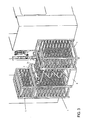
- FIG. 1 shows a schematic perspective view of a shelf magazine according to the present invention, wherein in FIG. 1 the gripping arm of a transfer unit grips a tool quiver located in a buffer.
- FIG. 1 can be removed, the shelf magazine of the present invention, a movable shelf module 1, a plurality of receiving devices 2 for receiving tools, a transfer unit 3, which passes the tools for the purpose of intermediate storage or application, and a lifting unit 4.
- the shelf module 1 is frame-like constructed as a shelf and has shelves 1a, which are formed as a simple L-shaped rails. These L-shaped rails run in such a way that a receiving device 2 described below can run displaceably on these rails in the direction of the carriage.
- FIG. 1 is apparent.
- the L-shaped rails in the respective shelf 1a are parallel to each other as in the Figures shown arranged so that the respective lower legs of the L-shape to each other.
- the vertical distance of the L-shaped rails and thus the shelves 1a in the shelf module 1 to each other, ie vertical height of each shelf, is selected according to the stored in the shelf module 1 tool. That is, a relatively large tool requires a relatively large distance of the shelves 1a in the vertical direction, whereas a relatively small tool allows a relatively short distance in the vertical direction of the shelves 1a.
- the shelf module 1 is mobile and can by means of a in FIG. 1 shown lift truck 11 are moved with, for example, electric drive. In this case, the lift truck 11 moves with its Hubwagengabeln 12 under the shelf module 1 and raises the shelf module 1 at. In order to enable a precise parking of the shelf module 1, suitable positioning aids such as pins or baffles may be provided on the floor (these are not shown).
- the shelf module 1 is expandable so that on the shelf module 1 at the top support means (not shown) are provided which allow stacking of another shelf module 1 on the shelf module 1, so that a plurality of shelf modules 1 can be positioned one above the other.
- a shelf module 1 is shown on the right side, on which no other shelf module is stacked.
- a shelf module 1 is shown, on the upper side of an additional shelf module 1 is arranged.
- the stacked shelf modules (such as on the left side of FIG. 1 ) may be the same or different Keep tools and thus have a mutually equal vertical distance of the shelves 1a or a different vertical distance of the shelves 1a.
- the respective lower shelf modules 1 may have Abstellfbiee, whereas the stacked on the top of the lower shelf modules 1 shelf modules 1 need not necessarily Abstellfbiee but may have appropriate integration facilities that allow a secure stacking. It is also possible to stack three or more shelf modules 1 one above the other.
- a receiving device 2 is arranged in each case, which serves to accommodate tools W.
- a receiving device 2 is provided in each shelf 1a .
- Each receiving device 2 is movable in the direction of the carriage relative to the associated shelf 1a along its L-shaped rails.
- Each receiving device 2 has tool receiving constructions, wherein, depending on the size of the tool, a receiving device 2 may have a single tool receiving structure or a plurality of tool receiving constructions. In the case of particularly large tools, therefore, the receiving device 2 has only one tool receiving structure, while with a smaller size of the tools, a receiving device 2 of the present invention can have several tool receiving constructions arranged next to one another. In the example of FIG.
- the receiving device 1 has the receiving device 2, which in the shelf module 1 on the right side of the representation of FIG. 1 is applied, eight juxtaposed tool receiving constructions on.
- the receiving device 2 has a longitudinal extent in (as in FIG. 1 shown) rectangular shape, with two opposite cross struts of this rectangular shape (in FIG. 1 the front and the rear cross member) have running surfaces on their undersides. These treads run on the L-shaped rails of the shelves 1a.
- each tool receiving structure has a groove shape.
- This groove shape is adapted to the shape and size of the respective tool to be deposited in it. Therefore, in the present invention, receptacles 2 with long groove shape for longer tools and short groove shape for shorter tools are conceivable.
- tool receiving structures are applicable in a stepped form, which allow safe storage of the respective tool stored therein, taking into account the contour of the respective tool (in the construction of the tool receiving structure). For the application of particularly heavy tools, the receiving device to increase the stabilization cross braces have.
- a transport lock is provided, which prevents the slipping out of the receiving devices 2 during transport (due to inclination, lateral impulses, etc.).
- the present invention comprises the lifting unit 4.
- This lifting unit 4 is preferably stationary and consists of a hinge construction with a receiving table 41 at the top of the lifting unit 4 and a drive.
- the drive provides for extending and retracting the receiving table 41 in the vertical direction.
- the shape of the Take-up table 41 at the top of the lifting unit 4 is adapted to receive a receiving device 2.
- the lifting unit 4 is extended / retracted so that its receiving table 41 is aligned with the corresponding receiving device 2 in the corresponding shelf 1a.
- the receiving table 41 of the lifting unit 4 therefore has a rectangular shape in the present embodiment, which corresponds to the rectangular shape of the receiving device 2.
- the receiving table 41 of the lifting unit 4 has on its upper side receiving surfaces, which are formed so that respective running surfaces, which are formed on the underside of the receiving device 2 as described above, can run.
- each receiving device 2 in the shelf 1a and on the running surfaces of the receiving table 41 of the lifting unit 4 are moved.
- the receiving device 2 is thereby moved by a drive which is assigned to the lifting unit 4. It makes sense that the drive can operate the modules on both sides of the lifting unit 4. This ensures that the individual shelf modules can be performed very easily. In special cases, however, it is also conceivable that the drive is also assigned to the module.
- the receiving table 41 of the lifting unit 4 has boundary walls between which the receiving device 2 can run. More specifically, the boundary walls of the take-up table 41 of the elevation unit extend adjacent to the upper treads of the take-up table 41 on the outside thereof (in FIG Fig. 1 the front and the rear side), so that on the upper running surfaces of the receiving table 41 daringly moving receiving device 2 runs between these boundary walls.
- the lifting unit 4 itself can be designed in various ways.
- the lifting unit 4 uses the Zieharmonika bin by means of articulated construction.
- Other types of construction may be used as long as extension and retraction of the take-up table 41 in the vertical direction and stopping of the take-up table 41 at transfer positions aligned with the respective shelf 1a are possible.
- the present invention further comprises the transfer unit 3.
- the transfer unit 3 serves to remove a tool W which is located on the receiving device 2 arranged on the upper side of the lifting unit 4 and to deposit it at a storage location, or to remove it from the storage location and to deposit it on the receiving device 2.
- the transfer unit 3 of the present embodiment may be provided, for example, with a tool changer as described in the patent DE 103 54 442 is described.
- a tool changer has a tool storage location in a vertically displaceable buffer for a tool which is removed from a gripper gripping the tool and transferred to a machine tool.
- the tool storage location in the buffer is designed as a holder which receives a tool holder (pot), in which the tool is seated. In this case, the tool is taken together with the tool quiver from the cache and passed.
- the transfer unit 3 of the present embodiment may have as the storage location the vertically displaceable buffer 33, as shown in FIG. 1 is shown.
- a tool holder 32 is a tool holder pot for receiving a tool W.
- Each tool holder 32 has an inner shape such as an inner cone corresponding to a cone shape formed on the tool.
- the tool in turn has the correspondingly formed outer cone, by means of which it can be used in the machine tool (in a spindle or another counterpart).
- the transfer unit 3 has a gripping arm 31.
- the gripper arm 31 is constructed as a hinge construction and can both on the respective receiving groove of the latch 33 (see Fig. 1 and Fig. 2 ) as well as the respective tools W on the receiving table 41 located on the receiving device 2 access when the receiving table 41 is arranged in the vertical position, which allows a transfer from receiving table 41 to gripping arm 31.
- the gripping arm 31, in the position in which it is maximally stretched, can grasp the tool W in the receiving form on the receiving table 41 farthest from the transfer unit 3, as shown in FIG Fig. 3 and Fig. 4 is shown.
- the gripping arm 31 can grasp a tool holder 32 together with the tool W located therein, and transfer both as one unit to the buffer 33 and deposit them there in the respective receiving groove.
- the lifting unit 4 then moves on or off in such a way that its receiving table 41 is aligned with the shelf 1a, the receiving device 2 of which is to transfer a tool W into the transfer unit 3.
- the running surfaces are aligned at the top of the receiving table 41 of the lifting unit 4 to the running surfaces of the shelf 1a (L-shaped rails), that is, they form corresponding extensions to each other.
- the receiving device 2 is pushed from the shelf 1a to the receiving table 41 of the lifting unit 4, wherein the receiving device 2 is guided by the boundary walls on the receiving table 41 of the lifting unit 4.
- the receiving device 2 has arrived at the movement stopper position on the receiving table 41 of the lifting unit 4, their horizontal running movement ends.
- the receiving table 41 of the lifting unit 4 is moved to the transfer position at which the gripper arm 31 receives the tool W by means of a tool quiver 32.
- the equipped with the tool holder 32 gripper arm 31 of the transfer unit 3 to the tool W, which is to be removed from the receiving device 2, extended, as shown in the FIGS. 1 and 2 is shown.
- tool holder 32 receives the tool W, for example, by a horizontal movement of the lifting unit in the tool longitudinal axis.
- the same drive as for retracting the receiving device 2 can also be used for this movement. If, in any case, an axial movement should be necessary for subsequent operations, this movement could also be carried out by a downstream component (transfer unit, robot, etc.).
- the gripper arm 31 pivots to the buffer 33 in such a way that the tool quiver, in which the tool W received now sits, is deposited in a receiving groove of the buffer 33, as shown in FIGS Figures 3 and 4 is shown.
- the lifting unit 4 can be lowered. Subsequently, the stored in the buffer 33 tool W can be used by the working machine 50.
- the procedure outlined above can also be carried out in the opposite manner, that is to say that a tool can be removed from the buffer 33 by means of gripping arm 31 and tool holder 32 and positioned on a receiving device 2 which has been arranged on the receiving table 41 of the lifting unit 4.
- FIG. 5 shows a further schematic perspective view of the shelf magazine according to the invention, in which the Working position of Fig. 1 and Fig. 2 from a different angle in order to facilitate the understanding of the invention.
- the shelf module 1 is mobile.
- the invention is also applicable to the case where at least one shelf module is fixed.
- the entire principle is theoretically conceivable rotated by 90 ° (according to the principle of a pharmacist's cabinet), wherein the shelf module a plurality of juxtaposed shelves are available.
- the shelf module 1 is conveyed by an electric pallet truck 11.
- the lift truck 11 can also be driven otherwise.
- the shelf module 1 has its own drive and is provided with wheels.
- the rack module 1 has wheels and can be moved by means of external drive (for example, even manually).
- the wheels should then identify a locking mechanism to prevent relative movement of the parked shelf module to the lifting unit.
- the lifting unit is anchored stationary on the ground.
- the lifting unit can also be anchored to the machine frame of the machine.
- the gripping arm of the transfer unit 3 transfers the tool W to a buffer store 33.
- the transfer unit 3 can also transfer a tool W directly to a tool changer.
- the transfer unit 3 can also transfer a tool W directly to a work machine 50.
- the tool receiving structures of the respective receiving means 2 has a groove shape which is adapted to the shape and size of the respective tool to be deposited in it.
- the inclusion of the objects is not only limited to the groove shape (gripper groove), there are also other possibilities conceivable (channel-shaped storage, etc.). It is also conceivable that the recording takes place without special shape, so that e.g. a workpiece blank with flat surfaces simply placed on the insert and then picked up via a suitable gripping system possibly with additional movements in the gripper arm and then transferred directly or via a buffer in the machine.
- the stored object to be transferred and used by the work machine 50 is a tool W used in a machine tool 50.
- the object may be an electrode used in an erosion machine 50.
- the object can be a workpiece. Further possible uses are conceivable because the principle underlying the present invention is not limited to the type of object. The invention is thus applicable to any suitable objects to be stored, transferred and used at a place of use.
Abstract
Description
Es sind verschiedene Regalmagazine im Stand der Technik bekannt. Regalmagazine sollen dazu in der Lage sein, eine möglichst breite Vielfalt an Werkzeugen oder ähnlichen Objekten in großer Zahl aufnehmen zu können und bereit zu halten, damit diese bei Bedarf aus dem Regalmagazin entnommen und entsprechend angewendet werden können.Various shelf magazines are known in the art. Shelf magazines should be able to accommodate as wide a variety of tools or similar objects in large numbers and ready to keep them so that they can be removed from the shelf magazine and used accordingly.
Daher muss ein Regalmagazin in der Lage sein, zum einen viele mitunter sehr verschiedene Werkzeuge oder entsprechende Objekte aufnehmen zu können und andererseits diese relativ schnell dem Nachfragenden zur Verfügung zu stellen. Die Bestückung und Entnahme von Werkzeugen/Objekten in das Regalmagazin und aus diesem heraus ist im Stand der Technik auf verschiedene Weise gelöst worden. Ein Problem hierbei ist im Stand der Technik, dass die Beschickungseinrichtungen/Entnahmeeinrichtungen aufgrund der verschiedenen Größen und Formen der Werkzeuge/Objekte so gebaut sein müssen, dass sie der Handhabung der verschiedenen Größen/Formen entsprechen können. Um daher ein große Flexibilität im Hinblick auf die Handhabbarkeit möglichst vieler Größen/Formen aufzuweisen, ist ein entsprechender Platzbedarf für die Beschickungseinrichtungen/Entnahmeeinrichtungen am Regalmagazin vonnöten.Therefore, a shelf magazine must be able to accommodate many sometimes very different tools or objects and on the other hand, these relatively quickly to the demanders to provide. The placement and removal of tools / objects in the shelf magazine and out of this has been solved in various ways in the prior art. One problem with this is in the prior art that, because of the different sizes and shapes of the tools / objects, the loaders / unloaders must be constructed to suit the handling of the various sizes / shapes. Therefore, to have a great deal of flexibility in terms of manageability as many sizes / shapes, is a corresponding footprint for the Feeding devices / removal devices on shelf magazine needed.
Die Aufgabe der vorliegenden Erfindung ist es, den Platzbedarf bei der Beschickung/Entnahme von Werkzeugen/Objekten an einem Regalmagazin zu ermöglichen.The object of the present invention is to enable the space required for the loading / unloading of tools / objects on a rack magazine.
Diese Aufgabe ist durch ein Regalmagazin mit den Merkmalen des Anspruchs 1 gelöst.This object is achieved by a shelf magazine with the features of claim 1.
Vorteilhafte Weiterbildungen der vorliegenden Erfindung sind in den abhängigen Ansprüchen aufgezeigt.Advantageous developments of the present invention are shown in the dependent claims.
In einem Regalmagazin mit den Merkmalen des Anspruchs 1 wird ein geringer Platzbedarf für das Gesamtsystem gewährleistet.In a rack magazine with the features of claim 1, a small footprint for the entire system is guaranteed.
In einem Regalmagazin mit den Merkmalen des Anspruchs 2 wird ein Werkzeug/Objekt sicher auf der Aufnahmeeinrichtung gelagert. Außerdem ist die Aufnahme/Abgabe durch die Übergabeeinheit einfach.In a rack magazine with the features of
In einem Regalmagazin mit den Merkmalen der Ansprüche 3 bis 6 wird eine optimale Packungsdichte für die Werkzeughandhabung ermöglicht.In a rack magazine with the features of
In einem Regalmagazin mit den Merkmalen des Anspruchs 6 ist eine technisch einfache und kostengünstige Verschiebung der Aufnahmeeinrichtung im Regalfach möglich.In a rack magazine with the features of claim 6, a technically simple and cost-effective displacement of the receiving device in the shelf is possible.
In einem Regalmagazin mit den Merkmalen des Anspruchs 7 ist eine genaue Ortsbeziehung zwischen Hubeinheit und jeweiligem Regalfach ermöglicht, was ein schnelles und genaues Verschieben der Aufnahmeeinrichtung erlaubt.In a rack magazine with the features of claim 7 a precise location relationship between the lifting unit and the respective shelf is possible, allowing a quick and accurate movement of the receiving device.
In einem Regalmagazin mit den Merkmalen des Anspruchs 8 sind die Übergabewege zwischen Hubeinheit und jeweiligem Regalfach, und zwischen Hubeinheit und Übergabeeinheit kurz, was den Platzbedarf für das Gesamtsystem noch stärker verringert.In a rack magazine with the features of claim 8, the transfer paths between the lifting unit and the respective shelf, and between the lifting unit and transfer unit are short, which reduces the space required for the overall system even more.
In einem Regalmagazin mit den Merkmalen der Ansprüche 9 und 10 ist das Regalmodul in einfacher Weise erweiterbar, so dass durch einfache Massnahmen eine große Anzahl an Werkzeugen/Objekten verwendbar ist. Außerdem können ganze Regalmodule schnell ausgetauscht werden. Die Rüstzeit verringert sich dadurch vorteilhaft.In a rack magazine with the features of claims 9 and 10, the shelf module is extensible in a simple manner, so that by simple measures a large number of tools / objects can be used. In addition, entire rack modules can be replaced quickly. The set-up time is reduced thereby advantageous.
Das Regalmagazin mit den Merkmalen des Anspruchs 11 sorgt dafür, dass ausgewählte Objekte für eine Arbeitsmaschine schnell zu Verfügung stehen.The shelf magazine with the features of
In einem Regalmagazin mit den Merkmalen des Anspruchs 12 ist ein schnelles und direktes Weitergeben von Objekten zwischen Arbeitsmaschine und Übergabeeinheit möglich.In a shelf magazine with the features of
In einem Regalmagazin mit den Merkmalen der Ansprüche 13 und 14 sind spezifische Anwendungen der erfindungsgemäßen Lösung möglich.In a shelf magazine with the features of claims 13 and 14, specific applications of the inventive solution are possible.
Die vorliegende Erfindung bietet eine Reihe an Vorteilen.The present invention offers a number of advantages.
Durch die vorliegende Erfindung wird für ein Regalmagazin eine optimale Packungsdichte durch entsprechende Gestaltung der Regalmodule erzielt.By means of the present invention, an optimal packing density is achieved for a shelf magazine by appropriate design of the shelf modules.
Der Platzbedarf für die Werkzeughandhabung ist gering.The space required for tool handling is low.
DasRegalmagazin ist auf einfache Weise erweiterbar durch einen zweiten Stellplatz für ein weiteres mobiles Regalmodul und / oder durch übereinander erfolgendes Stapeln der Regalmodule.The shelf magazine is easily expandable by a second slot for another mobile Shelf module and / or stacked by stacking the shelf modules.
Ein einfaches und schnelles Rüsten durch Austausch ganzer Regalmodule ist erzielbar.A simple and fast setup by replacing entire rack modules is achievable.
Ein mehrfaches Nutzen vorhandener Vorschubbewegungen ist möglich (z.B. kann das Ein- und Ausführen des Werkzeugköchers auf den Werkzeugkonus mit dem vorhandenen Achsantrieb der Hubeinheit erfolgen).A multiple use of existing feed movements is possible (for example, the insertion and removal of the tool holder on the tool cone can be done with the existing final drive of the lifting unit).
Es ist eine einfache Gestaltung der Regalmodule aufgrund geringer Toleranzanforderungen und fehlender eigener Achsantriebe möglich.It is a simple design of the shelf modules due to low tolerance requirements and missing own axle drives possible.
Die vorliegende Erfindung ist nachstehend anhand beigefügter Zeichnungen beschrieben, die die Erfindung in beispielartiger Weise veranschaulichen.The present invention will now be described with reference to the accompanying drawings, which illustrate the invention in an exemplary manner.
-
Figur 1 zeigt eine schematische perspektivische Ansicht eines Regalmagazins gemäß der vorliegenden Erfindung, wobei inFigur 1 der Greifarm einer Übergabeeinheit einen in einem Zwischenspeicher befindlichen Werkzeugköcher ergreift.FIG. 1 shows a schematic perspective view of a shelf magazine according to the present invention, wherein inFIG. 1 the gripping arm of a transfer unit grips a tool quiver located in a buffer. -
Figur 2 zeigt eine Draufsicht auf das Regalmagazin gemäßFigur 1 .FIG. 2 shows a plan view of the shelf magazine according toFIG. 1 , -
Figur 3 zeigt eine schematische perspektivische Ansicht des Regalmagazins gemäß Anspruch 1, wobei der Greifarm der Übergabeeinheit einen Werkzeugköcher ergreift, der ein auf einer Aufnahmeeinrichtung abgelegtes Werkzeug beinhaltet.FIG. 3 shows a schematic perspective view of the shelf magazine according to claim 1, wherein the gripping arm of the transfer unit engages a tool quiver, which includes a stored on a receiving device tool. -
Figur 4 zeigt eine schematische Draufsicht auf das Regalmagazin gemäßFigur 3 .FIG. 4 shows a schematic plan view of the shelf magazine according toFIG. 3 , -
Figur 5 zeigt eine weitere schematische perspektivische Ansicht des erfindungsgemäßen Regalmagazins.FIG. 5 shows a further schematic perspective view of the shelf magazine according to the invention.
Nachstehend ist ein Ausführungsbeispiel der vorliegenden Erfindung beispielartig beschrieben.Hereinafter, an embodiment of the present invention will be described by way of example.
Wie dies aus
Das Regalmodul 1 ist gestellartig als ein Regal aufgebaut und weist Regalfächer 1a auf, die als einfache L-förmige Schienen ausgebildet sind. Diese L-förmigen Schienen verlaufen wagerecht derart, dass eine nachstehend beschriebene Aufnahmeeinrichtung 2 auf diesen Schienen in wagerechter Richtung verschiebbar laufen kann. In dem Regalmodul 1 sind dabei die Regalfächer 1a übereinander angeordnet, wie dies aus
Das Regalmodul 1 ist mobil und kann mittels eines in
Das Regalmodul 1 gemäß der vorliegenden Erfindung ist so erweiterbar, dass auf dem Regalmodul 1 an der Oberseite Abstützeinrichtungen (nicht dargestellt) vorgesehen sind, die ein Stapeln eines weiteren Regalmodul 1 auf dem Regalmodul 1 ermöglichen, so dass mehrere Regalmodule 1 übereinander positioniert werden können. In
In den Regalfächern 1 ist jeweils eine Aufnahmeeinrichtung 2 angeordnet, die der Aufnahme von Werkzeugen W dient. Im Ausführungsbeispiel von
Die Werkzeugaufnahmekonstruktionen der jeweiligen Aufnahmeeinrichtungen 2 sind parallel zu den vorstehend beschriebenen Laufflächen an der Unterseite der Aufnahmeeinrichtung 2 ausgebildet. Insbesondere weist jede Werkzeugaufnahmekonstruktion eine Rillenform auf. Diese Rillenform ist an die Form und Größe des jeweiligen in ihr abzulegenden Werkzeugs angepasst. Daher sind in der vorliegenden Erfindung Aufnahmeeinrichtungen 2 mit langer Rillenform für längere Werkzeuge und kurzer Rillenform für kürzere Werkzeuge denkbar. Darüber hinaus sind Werkzeugaufnahmekonstruktionen in abgestufter Form anwendbar, die ein sicheres Aufbewahren des jeweiligen darin abgelegten Werkzeugs ermöglichen, wobei auf die Kontur des jeweiligen Werkzeugs Rücksicht genommen wird (bei der Konstruktion der Werkzeugaufnahmekonstruktion). Für die Anwendung besonders schwerer Werkzeuge kann die Aufnahmeeinrichtung zur Erhöhung der Stabilisierung Querverstrebungen aufweisen.The tool receiving structures of the respective
An den einzelnen Modulen ist eine Transportsicherung vorgesehen, die das Herausrutschen der Aufnahmeeinrichtungen 2 beim Transport (aufgrund Schrägstellung, seitlicher Impulse etc.) verhindert.At the individual modules, a transport lock is provided, which prevents the slipping out of the receiving
Die vorliegende Erfindung weist die Hubeinheit 4 auf.The present invention comprises the
Diese Hubeinheit 4 ist vorzugsweise ortsfest und besteht aus einer Gelenkkonstruktion mit einem Aufnahmetisch 41 an der Oberseite der Hubeinheit 4 und einem Antrieb. Der Antrieb sorgt für ein Ausfahren und Einfahren des Aufnahmetisches 41 in vertikaler Richtung. Die Form des Aufnahmetisches 41 an der Oberseite der Hubeinheit 4 ist daran angepasst, eine Aufnahmeeinrichtung 2 aufzunehmen. Dabei wird die Hubeinheit 4 so ausgefahren/eingefahren, dass ihr Aufnahmetisch 41 zu der entsprechenden Aufnahmeeinrichtung 2 im entsprechenden Regalfach 1a ausgerichtet ist. Der Aufnahmetisch 41 der Hubeinheit 4 weist daher im vorliegenden Ausführungsbeispiel eine Rechteckform auf, die der Rechteckform der Aufnahmeeinrichtung 2 entspricht. Der Aufnahmetisch 41 der Hubeinheit 4 weist an seiner Oberseite Aufnahmeflächen auf, die so ausgebildet sind, dass jeweilige Laufflächen, die an der Unterseite der Aufnahmeeinrichtung 2 wie vorstehend beschrieben ausgebildet sind, laufen können.This
Somit kann jede Aufnahmeeinrichtung 2 im Regalfach 1a und auf den Laufflächen des Aufnahmetischs 41 der Hubeinheit 4 bewegt werden. Idealerweise wird dabei die Aufnahmeeinrichtung 2 durch einen Antrieb, der der Hubeinheit 4 zugeordnet ist, bewegt. Sinnvollerweise kann der Antrieb die Module auf beiden Seiten der Hubeinheit 4 bedienen. Dadurch wird erreicht, dass die einzelnen Regalmodule sehr einfach ausgeführt werden können. In besonderen Fällen ist es jedoch auch denkbar, dass der Antrieb auch dem Modul zugeordnet ist.Thus, each receiving
Als zusätzliche Begrenzung weist der Aufnahmetisch 41 der Hubeinheit 4 Begrenzungswände auf, zwischen denen die Aufnahmeeinrichtung 2 laufen kann. Genauer gesagt, erstrecken sich die Begrenzungswände des Aufnahmetisches 41 der Hubeinheit benachbart zu den oberen Laufflächen des Aufnahmetisches 41 an deren Außenseite (in
Die Hubeinheit 4 selbst kann auf verschiedene Weise ausgeführt sein. Im vorliegenden Ausführungsbeispiel von
Die vorliegende Erfindung weist des weiteren die Übergabeeinheit 3 auf. Die Übergabeeinheit 3 dient dazu, ein Werkzeug W, das sich auf der an der Oberseite der Hubeinheit 4 angeordneten Aufnahmeeinrichtung 2 befindet, zu entnehmen und an einem Aufbewahrungsort abzulagern, oder von dem Aufbewahrungsort zu entnehmen und auf der Aufnahmeeinrichtung 2 abzulagern. Die Übergabeeinheit 3 des vorliegenden Ausführungsbeispiels kann beispielsweise mit einem Werkzeugwechsler versehen sein, wie er in dem Patent
Wie vorstehend beschrieben, kann die Übergabeeinheit 3 des vorliegenden Ausführungsbeispiels als Aufbewahrungsort den vertikal verschiebbaren Zwischenspeicher 33 aufweisen, wie dies in
Die Übergabeeinheit 3 weist einen Greifarm 31 auf. Der Greifarm 31 ist als Gelenkkonstruktion aufgebaut und kann sowohl auf die jeweilige Aufnahmenut des Zwischenspeichers 33 (siehe
Daher kann der Greifarm 31 einen Werkzeugköcher 32 samt dem darin befindlichen Werkzeug W ergreifen und beide als eine Einheit zu dem Zwischenspeicher 33 übergeben und dort in der jeweiligen Aufnahmenut ablagern.Therefore, the
Nachstehend ist die Funktionsweise des vorliegenden Ausführungsbeispiels beschrieben.The operation of the present embodiment will be described below.
Das Regalmodul 1, in welchem sich in den jeweiligen Regalfächern 1a Aufnahmeeinrichtungen 2 befinden, in denen wiederum Werkzeuge W aufbewahrt sind, wird so an die Seite der Hubeinheit 4 geschoben, dass bei Abstellen des Regalmoduls 1 die Aufnahmeinrichtungen 2 aus den Regalfächern 1a ausfahren können und auf den Aufnahmetisch 41 der Hubeinheit 4 gelangen können, wenn der Aufnahmetisch 41 der Hubeinheit 4 in der entsprechenden Höhenposition des in Frage kommenden Regalfachs 1a bewegt wird.The shelf module 1, in which there are
Dann fährt die Hubeinheit 4 so aus bzw. ein, dass ihr Aufnahmetisch 41 an dem Regalfach 1a ausgerichtet ist, dessen Aufnahmeeinrichtung 2 ein Werkzeug W in die Übergabeeinheit 3 übergeben soll. Dabei sind die Laufflächen an der Oberseite des Aufnahmetischs 41 der Hubeinheit 4 zu den Laufflächen des Regalfachs 1a (L-förmige Schienen) ausgerichtet, das heißt, sie bilden entsprechende Verlängerungen zueinander. Dann wird die Aufnahmeeinrichtung 2 aus dem Regalfach 1a zu dem Aufnahmetisch 41 der Hubeinheit 4 geschoben, wobei die Aufnahmeeinrichtung 2 durch die Begrenzungswände an dem Aufnahmetisch 41 der Hubeinheit 4 geführt wird. Wenn die Aufnahmeeinrichtung 2 an der Bewegungsstopperposition auf dem Aufnahmetisch 41 der Hubeinheit 4 angelangt ist, endet ihre waagerechte Laufbewegung.The
Nun wird der Aufnahmetisch 41 der Hubeinheit 4 zu der Übergabeposition verschoben, an der der Greifarm 31 mittels Werkzeugköcher 32 das Werkzeug W aufnimmt.Now, the receiving table 41 of the
Wenn der Aufnahmetisch 41 der Hubeinheit 4 seine Übergabeposition erreicht hat, wird der mit dem Werkzeugköcher 32 ausgestattete Greifarm 31 der Übergabeeinheit 3 zu dem Werkzeug W, welches aus der Aufnahmeeinrichtung 2 entnommen werden soll, ausgefahren, wie dies in den
Daraufhin schwenkt der Greifarm 31 zu dem Zwischenspeicher 33 derart, dass der Werkzeugköcher, in dem nunmehr das aufgenommene Werkzeug W sitzt, in eine Aufnahmenut des Zwischenspeichers 33 abgelegt wird, wie dies in den
Der vorstehend dargelegte Ablauf kann auch in entgegengesetzter Weise ausgeführt werden, das heißt, aus dem Zwischenspeicher 33 kann mittels Greifarm 31 und Werkzeugköcher 32 ein Werkzeug entnommen und auf einer Aufnahmeeinrichtung 2 positioniert werden, die auf dem Aufnahmetisch 41 der Hubeinheit 4 angeordnet worden ist.The procedure outlined above can also be carried out in the opposite manner, that is to say that a tool can be removed from the
Das vorstehend anhand der Zeichnungen beschriebene Ausführungsbeispiel gibt die Idee der vorliegenden Erfindung lediglich beispielartig wieder. Die vorliegende Erfindung ist nicht auf das Ausführungsbeispiel allein beschränkt. Beispielsweise kann die vorliegende Erfindung in folgender Weise abgewandelt werden.The embodiment described above with reference to the drawings represents the idea of the present invention by way of example only. The present invention is not limited to the embodiment alone. For example, the present invention may be modified in the following manner.
Im vorstehend beschriebenen Ausführungsbeispiel ist das Regalmodul 1 mobil. Die Erfindung ist auch auf den Fall anwendbar, bei dem zumindest ein Regalmodul fixiert ist. Ausserdem ist das gesamte Prinzip ist theoretisch auch um 90° gedreht denkbar (nach dem Prinzip eines Apothekerschranks), wobei im Regalmodul eine Vielzahl an nebeneinander angeordneter Regalfächer vorhanden sind.In the embodiment described above, the shelf module 1 is mobile. The invention is also applicable to the case where at least one shelf module is fixed. In addition, the entire principle is theoretically conceivable rotated by 90 ° (according to the principle of a pharmacist's cabinet), wherein the shelf module a plurality of juxtaposed shelves are available.
Im vorstehend beschriebenen Ausführungsbeispiel wird das Regalmodul 1 durch einen Elektrohubwagen 11 befördert. Der Hubwagen 11 kann natürlich auch anderweitig angetrieben werden. Als Alternative ist außerdem vorstellbar, dass das Regalmodul 1 einen eigenen Antrieb aufweist und mit Rädern versehen ist. Als weitere Alternative ist vorstellbar, dass das Regalmodul 1 Räder aufweist und mittels externem Antrieb (z.B. sogar manuell) bewegt werden kann.In the embodiment described above, the shelf module 1 is conveyed by an
Vorzugsweise sollten die Räder dann einen Arretiermechanismus ausweisen, um eine Relativbewegung des abgestellten Regalmoduls zur Hubeinheit zu vermeiden.Preferably, the wheels should then identify a locking mechanism to prevent relative movement of the parked shelf module to the lifting unit.
Im vorstehend beschriebenen Ausführungsbeispiel ist die Hubeinheit ortsfest am Boden verankert. Die Hubeinheit kann auch am Maschinengestell der Maschine verankert sein.In the embodiment described above, the lifting unit is anchored stationary on the ground. The lifting unit can also be anchored to the machine frame of the machine.
In vorliegendem Ausführungsbeispiel übergibt der Greifarm der Übergabeeinheit 3 das Werkzeug W an einen Zwischenspeicher 33. Als Alternative kann die Übergabeeinheit 3 ein Werkzeug W auch direkt zu einem Werkzeugwechsler übergeben. Als weitere Alternative kann die Übergabeeinheit 3 ein Werkzeug W auch direkt zu einer Arbeitsmaschine 50 übergeben.In the present exemplary embodiment, the gripping arm of the
In vorliegendem Ausführungsbeispiel weist die Werkzeugaufnahmekonstruktionen der jeweiligen Aufnahmeeinrichtungen 2 eine Rillenform auf, die an die Form und Größe des jeweiligen in ihr abzulegenden Werkzeugs angepasst ist. Die Aufnahme der Objekte ist nicht nur auf die Rillenform (Greiferrille) beschränkt, es sind auch andere Möglichkeiten denkbar (rinnenförmig Ablage etc.). Auch ist vorstellbar, dass die Aufnahme ohne spezielle Form erfolgt, so dass z.B. ein Werkstück-Rohling mit ebenen Flächen einfach auf den Einschub gelegt und dann über ein geeignetes Greifsystem evtl. mit zusätzlichen Bewegungen im Greifarm abgeholt und dann direkt oder über einen Puffer in die Bearbeitungsmaschine übergeben wird.In the present embodiment, the tool receiving structures of the respective receiving means 2 has a groove shape which is adapted to the shape and size of the respective tool to be deposited in it. The inclusion of the objects is not only limited to the groove shape (gripper groove), there are also other possibilities conceivable (channel-shaped storage, etc.). It is also conceivable that the recording takes place without special shape, so that e.g. a workpiece blank with flat surfaces simply placed on the insert and then picked up via a suitable gripping system possibly with additional movements in the gripper arm and then transferred directly or via a buffer in the machine.
In vorliegendem Ausführungsbeispiel ist das gelagerte, zu übergebende und durch die Arbeitsmaschine 50 verwendete Objekt ein Werkzeug W, das in einer Werkzeugmaschine 50 verwendet wird. Als Alternative kann das Objekt eine Elektrode ist, die in einer Erodiermaschine 50 verwendet wird. Ausserdem kann das Objekt ein Werkstück sein. Weitere Einsatzmöglichkeiten sind denkbar, denn das der vorliegenden Erfindung zugrunde liegende Prinzip ist nicht auf die Art des Objekts beschränkt. Die Erfindung ist somit auf jegliche geeignete zu lagernde, zu übergebende und an einem Verwendungsort zu verwendende Objekte anwendbar.In the present embodiment, the stored object to be transferred and used by the
- 11
- Regalmodulrack module
- 1a1a
- Regalfachshelf
- 22
- Aufnahmeeinrichtungrecording device
- 33
- ÜbergabeeinheitTransfer unit
- 44
- Hubeinheitlifting unit
- 1111
- Elektrohubwagenpallet stackers
- 1212
- Hubwagengabelfork lift trucks
- 3131
- Greifarmclaw arm
- 3232
- Werkzeugköchertool sheath
- 3333
- Zwischenspeichercache
- 4141
- AufnahmetischShooting table
- 5050
- Arbeitsmaschineworking machine
- WW
- Werkzeug (Objekt)Tool (object)
Claims (16)
wobei jedem Regalfach (1a) eine seitlich einschiebbare Aufnahmeeinrichtung (2) zuweisbar ist, und wobei jede Aufnahmeeinrichtung (2) mindestens eine Objektaufnahmekonstruktion für die sichere Ablage eines Objekts (W) aufweist;
wherein each shelf (1a) is assignable to a laterally insertable receptacle (2), and wherein each receptacle (2) has at least one object receptacle for the secure placement of an object (W);
jede Aufnahmeeinrichtung (2) eine Objektaufnahmekonstruktion für je ein Objekt (W) aufweist, wobei die Objektaufnahmekonstruktion an das Objekt (W) derart angepasst ist, dass sie das auf ihr abgelegte Objekt (W) abstützen kann, und
die Aufnahmeeinrichtung (2) in das Regalfach (1a) seitlich horizontal einschiebbar ist.Shelf magazine according to claim 1, wherein
each receptacle (2) has an object receptacle for each object (W), the object receptacle being adapted to the object (W) so as to support the object (W) deposited thereon, and
the receiving device (2) in the shelf (1 a) is laterally inserted horizontally.
zumindest eine Aufnahmeeinrichtung (2) mehrere Objektaufnahmekonstruktionen in Schieberichtung der Aufnahmeeinrichtung (2) nebeneinander angeordnet derart aufweist, dass sie mehrere Objekte (W) benachbart aufnehmen kann.Shelf magazine according to claim 2, wherein
at least one receiving device (2) a plurality of object receiving constructions in the sliding direction of the receiving device (2) arranged side by side such that they can accommodate a plurality of objects (W) adjacent.
Größe und zueinander gebildeter Abstand der Objektaufnahmekonstruktion(en) der Aufnahmeeinrichtung (2) an ein jeweiliges abzulagerndes Objekt (W) derart angepasst sind, dass möglichst viele Objekte (W) in Reihe auf einer Aufnahmeeinrichtung (2) lagerbar sind.Shelf magazine according to one of claims 2 and 3, wherein
Size and mutually formed distance of the object receiving structure (s) of the receiving device (2) to a respective object to be deposited (W) are adapted such that as many objects (W) in series on a receiving device (2) are storable.
im Regalgrundgerüst (1) die Vielzahl an Regalfächern (1a) nebeneinander oder vertikal übereinander angeordnet sind, und
die vertikale Höhe jedes Regalfachs (1a) an jeweils die maximale Größe des Objekts (W) anpassbar ist, das auf der diesem Regalfach (1a) zugewiesenen Aufnahmeeinrichtung (2) abgelagert wird.Shelf magazine according to one of claims 1 to 4, wherein
in the shelf framework (1) the plurality of shelves (1a) are arranged side by side or vertically one above the other, and
the vertical height of each shelf (1a) is adaptable to the maximum size of the object (W) which is deposited on the receiving device (2) assigned to this shelf (1a).
jedes Regalfach (1a) Schienen aufweist, auf denen die Aufnahmeeinrichtung (2) bewegbar ist.Shelf magazine according to one of claims 1 to 5, wherein
each shelf (1a) has rails on which the receiving device (2) is movable.
die Hubeinheit (4) die Aufnahmeeinrichtung (2) vertikal versetzt, ortsfest am Boden oder am Maschinengestell einer die Objekte (W) handhabenden Maschine verankert ist und am Boden neben der Hubeinheit (4) Positionierhilfen für ein genaues Positionieren des Regalgrundgerüsts (1) vorgesehen sind.Shelf magazine according to one of claims 1 to 6, wherein
the lifting unit (4) the receiving device (2) vertically offset, fixed to the ground or on the machine frame of the objects (W) handling machine is anchored and on the ground next to the lifting unit (4) positioning aids for accurate positioning of the shelf frame (1) are provided ,
die Hubeinheit (4) einen Aufnahmetisch (41) zur Aufnahme der Aufnahmeeinrichtung (2) in horizontal sich erstreckender Rechteckform mit Längsseiten, denen gegenüber das Regalgrundgerüst (1) positionierbar ist, und Querseiten aufweist, wobei im Bereich jenseits einer Querseite die Übergabeeinheit (3) angeordnet ist.Shelf magazine according to one of claims 1 to 7, wherein
the lifting unit (4) has a receiving table (41) for receiving the receiving device (2) in a horizontally extending rectangular shape with longitudinal sides against which the rack frame (1) can be positioned, and lateral sides, wherein in the area beyond a transverse side the transfer unit (3) is arranged.
an beiden Längsseiten Regalgrundgerüste (1) positionierbar sind.Shelf magazine according to claim 8, wherein
Shelf bases (1) can be positioned on both longitudinal sides.
das Regalgrundgerüst (1) vertikal erweiterbar derart ist, dass auf ein Regalgrundgerüst (1) zumindest ein weiteres Regalgrundgerüst (1) stapelbar ist.Shelf magazine according to one of claims 1 to 9, wherein
the shelf framework (1) is vertically expandable such that at least one further rack frame (1) can be stacked on a shelf framework (1).
die Übergabeeinheit (3) mit einer Arbeitsmaschine (50) direkt gekoppelt ist, die das Objekt (W) von der Übergabeeinheit (3) aufnehmen, handhaben und wieder an die Übergabeeinheit (3) abgeben kann.Shelf magazine according to one of claims 1 to 10, wherein
the transfer unit (3) is directly coupled to a work machine (50) which can pick up, handle and return the object (W) from the transfer unit (3) to the transfer unit (3).
das Objekt (W) ein Werkzeug ist, das in einer Werkzeugmaschine verwendet wird.Shelf magazine according to one of claims 1 to 12, wherein
the object (W) is a tool used in a machine tool.
das Objekt (W) eine Elektrode ist, die in einer Erodiermaschine verwendet wird.Shelf magazine according to one of claims 1 to 12, wherein
the object (W) is an electrode used in an EDM machine.
Applications Claiming Priority (1)
| Application Number | Priority Date | Filing Date | Title |
|---|---|---|---|
| DE102010001724A DE102010001724B4 (en) | 2010-02-09 | 2010-02-09 | shelf magazine |
Publications (4)
| Publication Number | Publication Date |
|---|---|
| EP2353778A2 true EP2353778A2 (en) | 2011-08-10 |
| EP2353778A3 EP2353778A3 (en) | 2011-10-26 |
| EP2353778B1 EP2353778B1 (en) | 2014-03-12 |
| EP2353778B8 EP2353778B8 (en) | 2014-06-25 |
Family
ID=44023040
Family Applications (1)
| Application Number | Title | Priority Date | Filing Date |
|---|---|---|---|
| EP11152461.7A Not-in-force EP2353778B8 (en) | 2010-02-09 | 2011-01-28 | Storage rack |
Country Status (6)
| Country | Link |
|---|---|
| US (1) | US20110194917A1 (en) |
| EP (1) | EP2353778B8 (en) |
| JP (1) | JP2011178563A (en) |
| CN (1) | CN102189538A (en) |
| DE (1) | DE102010001724B4 (en) |
| ES (1) | ES2461993T3 (en) |
Cited By (3)
| Publication number | Priority date | Publication date | Assignee | Title |
|---|---|---|---|---|
| EP3520956A1 (en) * | 2018-01-30 | 2019-08-07 | DECKEL MAHO Pfronten GmbH | Feeding device for a tool holder of a machine tool and method for changing a tool on a tool holder |
| CN111123189A (en) * | 2019-12-25 | 2020-05-08 | 国网北京市电力公司 | Temperature rise test device for metering box |
| WO2021249810A1 (en) | 2020-06-12 | 2021-12-16 | Dematic Gmbh | Goods-storage and order-fulfillment system |
Families Citing this family (23)
| Publication number | Priority date | Publication date | Assignee | Title |
|---|---|---|---|---|
| DE102011076595A1 (en) * | 2011-05-27 | 2012-11-29 | Homag Holzbearbeitungssysteme Gmbh | processing device |
| JP5733580B2 (en) * | 2012-11-13 | 2015-06-10 | 株式会社ダイフク | Article conveying apparatus and article storage facility provided with the same |
| CN104210797A (en) * | 2013-06-03 | 2014-12-17 | 昆山飞达磨具制造有限公司 | Grinding wheel storage cabinet |
| DE102013106427B4 (en) | 2013-06-19 | 2021-02-25 | Klaus Hofmann | Process for providing work equipment and a charging system for carrying out the process |
| CN104477550A (en) * | 2014-12-10 | 2015-04-01 | 马瑞利汽车零部件(芜湖)有限公司 | Auxiliary conveying shelf for boxes |
| CN104647327B (en) * | 2015-02-10 | 2017-02-01 | 安徽安凯汽车股份有限公司 | Combined storing and transferring tool of valves for passenger car |
| DE102015116729A1 (en) | 2015-10-01 | 2017-04-06 | Mikromat Gmbh | Method and device for process design during a machine feed and / or machine removal |
| CN106041846A (en) * | 2016-07-26 | 2016-10-26 | 苏州科明纺织有限公司 | Multi-layer textile roll frame |
| US10647531B2 (en) * | 2016-11-08 | 2020-05-12 | Greenheart Farms, Inc. | Independently automated loading system for unitized loads into a covered multi-level transporter |
| JP6855025B2 (en) * | 2017-01-16 | 2021-04-07 | 浙江国自機器人技術股▲ふん▼有限公司Zhejiang Guozi Robotics Co., Ltd. | Robot carrying a container |
| FR3054465B1 (en) * | 2017-02-17 | 2024-02-02 | Jerome Prevost | UNIVERSAL MAGAZINE FOR SUPPLYING BLANKS AND RECEIVING MACHINED PARTS OF A MACHINE TOOL. |
| CN106829297B (en) * | 2017-04-16 | 2018-07-31 | 嘉峪关市三川物流有限公司 | A kind of ferris wheel type Intelligent storage device |
| DE202017106597U1 (en) * | 2017-10-30 | 2019-01-31 | Aberu Gmbh | Device for moving stackable charge carriers |
| DE102018119280A1 (en) | 2018-08-08 | 2020-02-13 | Homag Bohrsysteme Gmbh | Workpiece handling device and method for batch processing of plate-shaped workpieces |
| CA3118772A1 (en) * | 2018-11-05 | 2020-05-14 | Simon Tiwha Enterprises Pty Ltd | Apparatus for use with a display unit |
| CN110803437B (en) * | 2019-11-03 | 2024-01-30 | 泰州市宇锋机械有限公司 | Cabinet is placed to five metals |
| CN110803438B (en) * | 2019-11-03 | 2024-01-30 | 江苏诺丁金属科技有限公司 | Hardware storage equipment |
| CN110900278B (en) * | 2019-12-12 | 2022-03-22 | 湖北文理学院 | Tool changing system of multi-machine tool magazine |
| CN111251267A (en) * | 2020-03-06 | 2020-06-09 | 中冶天工集团有限公司 | Storage tool for anode row of tank type electric dust remover and use method |
| CN111392184A (en) * | 2020-04-24 | 2020-07-10 | 惠州市东一钢结构有限公司 | Storage rack for placing steel |
| CN111591654B (en) * | 2020-06-09 | 2021-07-02 | 国网冀北综合能源服务有限公司 | Power equipment storage system |
| CN112722557B (en) * | 2020-12-30 | 2022-05-10 | 客来福家居股份有限公司 | Furniture board detects with panel rack |
| CN113334336B (en) * | 2021-05-21 | 2022-11-04 | 蓝海建设集团有限公司 | A deposit structure for on-spot reinforcing bar of depositing |
Citations (1)
| Publication number | Priority date | Publication date | Assignee | Title |
|---|---|---|---|---|
| DE10354442A1 (en) | 2003-11-21 | 2005-06-23 | Miksch Gmbh | Tool changing system for machine tool has intermediate magazine for tools and has gripping arm with two jaws removing individual tools from holders and moving them to machine spindle |
Family Cites Families (24)
| Publication number | Priority date | Publication date | Assignee | Title |
|---|---|---|---|---|
| JPS59108622A (en) * | 1982-12-08 | 1984-06-23 | Kanto Seiki Kk | Automatic handling system apparatus in factory |
| JPS60131144A (en) * | 1983-12-19 | 1985-07-12 | Toshiba Corp | Work feeder |
| JPH0653333B2 (en) * | 1985-07-19 | 1994-07-20 | キヤノン株式会社 | Automatic supply device for goods |
| JPS63200941A (en) * | 1987-02-13 | 1988-08-19 | Kyoritsu Seiki Kk | Automatic work and tool exchanger in nc compound machine tool |
| DE3715874C1 (en) * | 1987-05-01 | 1988-10-13 | Werner & Kolb Werkzeugmasch | Device for changing tools of a numerically controlled machining center |
| EP0302542B1 (en) * | 1987-07-14 | 1994-01-26 | Koninklijke Philips Electronics N.V. | Apparatus for the transport of carriers from and to a positioning device, and selection device for use in such an apparatus |
| JPH01124505A (en) * | 1987-11-04 | 1989-05-17 | Nec Corp | Automatic component dispenser |
| DE3824328C1 (en) * | 1988-07-18 | 1989-12-21 | Kone-Anlagenbau Gmbh, 8900 Augsburg, De | |
| JP2575819Y2 (en) * | 1992-01-27 | 1998-07-02 | セイレイ工業株式会社 | Rotary seedling growing machine |
| CN1189436A (en) * | 1997-01-28 | 1998-08-05 | 三星电子株式会社 | Tray supplying apparatus |
| DE29723886U1 (en) * | 1997-04-29 | 1999-04-22 | Promot Ind Automatisierungs Sy | Handling system for workpieces with stacking cell for workpiece carriers |
| JP3380741B2 (en) * | 1998-03-26 | 2003-02-24 | 住友ゴム工業株式会社 | Bead pick-up device |
| JP3491557B2 (en) * | 1999-04-22 | 2004-01-26 | 松下電器産業株式会社 | Tray feeder for supplying electronic components |
| JP2001150276A (en) * | 1999-11-24 | 2001-06-05 | Olympus Optical Co Ltd | Machine tool and machine tool management method |
| JP3502047B2 (en) * | 2001-02-01 | 2004-03-02 | 日酸Tanaka株式会社 | Cutting system |
| US6678583B2 (en) * | 2001-08-06 | 2004-01-13 | Seminet, Inc. | Robotic storage buffer system for substrate carrier pods |
| JP2004345837A (en) * | 2003-05-26 | 2004-12-09 | Central Uni Co Ltd | Storage device for medical treatment |
| JP4449363B2 (en) * | 2003-08-08 | 2010-04-14 | 株式会社Ihi | Book entry / exit method and automatic library |
| US7806644B2 (en) * | 2004-04-30 | 2010-10-05 | Yuyama Mfg. Co., Ltd. | Tray discharge device |
| EP1607174A1 (en) * | 2004-06-15 | 2005-12-21 | Zimmer & Kreim GmbH & Co. KG | Device for loading and unloading tools into/from the tool magazine of a machine-tool |
| DE102005036695B4 (en) * | 2005-08-04 | 2007-07-26 | A U E Automations- Und Einstelltechnik Kassel Gmbh | Deployment space and method for providing workpieces for an automated processing station |
| US8602954B2 (en) * | 2008-02-22 | 2013-12-10 | Makino Milling Machine Co., Ltd. | Tool magazine |
| FR2938508B1 (en) * | 2008-11-14 | 2010-12-17 | Sidel Participations | COMBINED PALLETIZATION INSTALLATION WITH SECURE ACCESS |
| DE102009008647A1 (en) * | 2009-02-12 | 2010-09-09 | Deckel Maho Pfronten Gmbh | System for changing and inserting or presenting tools on a machine tool and tool magazine for storing tools |
-
2010
- 2010-02-09 DE DE102010001724A patent/DE102010001724B4/en not_active Expired - Fee Related
-
2011
- 2011-01-28 EP EP11152461.7A patent/EP2353778B8/en not_active Not-in-force
- 2011-01-28 ES ES11152461.7T patent/ES2461993T3/en active Active
- 2011-02-08 US US13/023,436 patent/US20110194917A1/en not_active Abandoned
- 2011-02-08 JP JP2011024554A patent/JP2011178563A/en active Pending
- 2011-02-09 CN CN2011100394404A patent/CN102189538A/en active Pending
Patent Citations (1)
| Publication number | Priority date | Publication date | Assignee | Title |
|---|---|---|---|---|
| DE10354442A1 (en) | 2003-11-21 | 2005-06-23 | Miksch Gmbh | Tool changing system for machine tool has intermediate magazine for tools and has gripping arm with two jaws removing individual tools from holders and moving them to machine spindle |
Cited By (4)
| Publication number | Priority date | Publication date | Assignee | Title |
|---|---|---|---|---|
| EP3520956A1 (en) * | 2018-01-30 | 2019-08-07 | DECKEL MAHO Pfronten GmbH | Feeding device for a tool holder of a machine tool and method for changing a tool on a tool holder |
| CN111123189A (en) * | 2019-12-25 | 2020-05-08 | 国网北京市电力公司 | Temperature rise test device for metering box |
| WO2021249810A1 (en) | 2020-06-12 | 2021-12-16 | Dematic Gmbh | Goods-storage and order-fulfillment system |
| DE102020115619A1 (en) | 2020-06-12 | 2021-12-16 | Dematic Gmbh | Warehouse and order fulfillment system |
Also Published As
| Publication number | Publication date |
|---|---|
| CN102189538A (en) | 2011-09-21 |
| EP2353778B8 (en) | 2014-06-25 |
| ES2461993T3 (en) | 2014-05-22 |
| US20110194917A1 (en) | 2011-08-11 |
| JP2011178563A (en) | 2011-09-15 |
| EP2353778A3 (en) | 2011-10-26 |
| EP2353778B1 (en) | 2014-03-12 |
| DE102010001724B4 (en) | 2012-02-02 |
| DE102010001724A1 (en) | 2011-08-11 |
Similar Documents
| Publication | Publication Date | Title |
|---|---|---|
| DE102010001724B4 (en) | shelf magazine | |
| DE102013009340B4 (en) | Device and method for storing and retrieving stackable containers | |
| DE202016009161U1 (en) | storage system | |
| EP3579987B1 (en) | Bending tool storage device and method for feeding a press brake | |
| DE112009001363T5 (en) | Apparatus and methods used to load, move and deposit packages in an automated warehouse | |
| DE102005009695A1 (en) | Shelf storage and method for relocating stored goods in a shelf warehouse | |
| DE2021611C2 (en) | Storage and retrieval vehicle | |
| DE4422240A1 (en) | Method and device for handling transport stands | |
| EP2746193B1 (en) | Vehicle for a warehouse, stacker crane, warehouse and corresponding method | |
| WO1994007775A1 (en) | Apparatus for loading and unloading load-bearing elements onto and off shelving | |
| AT516624B1 (en) | Tool magazine and arrangement with such | |
| EP3782932B1 (en) | Stack storage assembly | |
| EP3094576B1 (en) | System formed by shelving unit and corresponding telescopic load receiving means without width adjustment | |
| EP2143667A1 (en) | Storage device for bulk goods and corresponding method | |
| DE4432856C2 (en) | Pallet pick-up device | |
| DE102017114643A1 (en) | Storage and retrieval machine suitable for use in a high-bay warehouse | |
| EP0352785A1 (en) | Device for manipulating and storing pallets and pallet-like or other objects | |
| EP1862405B1 (en) | Method for gripping piece goods using gripper devices of an input and output system and device therefor | |
| DE202020101328U1 (en) | Device of a tool magazine and tool magazine | |
| DE10140643A1 (en) | Warehouse container storage system has rack insert/removal unit with pick-up arms and linked to control system | |
| EP2868600B1 (en) | Storage and storage method | |
| DE102016122117B4 (en) | Body construction plant, with a rack system, for processing and/or assembling body components | |
| DE2914404A1 (en) | SHELF CONTROL UNIT | |
| DE2031601A1 (en) | Stacking device | |
| EP4337574A1 (en) | Sorting device |
Legal Events
| Date | Code | Title | Description |
|---|---|---|---|
| PUAI | Public reference made under article 153(3) epc to a published international application that has entered the european phase |
Free format text: ORIGINAL CODE: 0009012 |
|
| AK | Designated contracting states |
Kind code of ref document: A2 Designated state(s): AL AT BE BG CH CY CZ DE DK EE ES FI FR GB GR HR HU IE IS IT LI LT LU LV MC MK MT NL NO PL PT RO RS SE SI SK SM TR |
|
| AX | Request for extension of the european patent |
Extension state: BA ME |
|
| PUAL | Search report despatched |
Free format text: ORIGINAL CODE: 0009013 |
|
| AK | Designated contracting states |
Kind code of ref document: A3 Designated state(s): AL AT BE BG CH CY CZ DE DK EE ES FI FR GB GR HR HU IE IS IT LI LT LU LV MC MK MT NL NO PL PT RO RS SE SI SK SM TR |
|
| AX | Request for extension of the european patent |
Extension state: BA ME |
|
| RIC1 | Information provided on ipc code assigned before grant |
Ipc: B23Q 3/155 20060101AFI20110922BHEP Ipc: B23Q 7/00 20060101ALI20110922BHEP Ipc: B65G 1/10 20060101ALI20110922BHEP |
|
| 17P | Request for examination filed |
Effective date: 20111124 |
|
| 17Q | First examination report despatched |
Effective date: 20120221 |
|
| GRAP | Despatch of communication of intention to grant a patent |
Free format text: ORIGINAL CODE: EPIDOSNIGR1 |
|
| INTG | Intention to grant announced |
Effective date: 20131211 |
|
| GRAS | Grant fee paid |
Free format text: ORIGINAL CODE: EPIDOSNIGR3 |
|
| GRAA | (expected) grant |
Free format text: ORIGINAL CODE: 0009210 |
|
| AK | Designated contracting states |
Kind code of ref document: B1 Designated state(s): AL AT BE BG CH CY CZ DE DK EE ES FI FR GB GR HR HU IE IS IT LI LT LU LV MC MK MT NL NO PL PT RO RS SE SI SK SM TR |
|
| REG | Reference to a national code |
Ref country code: GB Ref legal event code: FG4D Free format text: NOT ENGLISH |
|
| REG | Reference to a national code |
Ref country code: CH Ref legal event code: EP Ref country code: CH Ref legal event code: NV Representative=s name: NOVAGRAAF INTERNATIONAL SA, CH |
|
| REG | Reference to a national code |
Ref country code: AT Ref legal event code: REF Ref document number: 655914 Country of ref document: AT Kind code of ref document: T Effective date: 20140315 |
|
| RBV | Designated contracting states (corrected) |
Designated state(s): AL AT BE BG CH CY CZ DK EE ES FI FR GB GR HR HU IE IS IT LI LT LU LV MC MK MT NL NO PL PT RO RS SE SI SK SM TR |
|
| REG | Reference to a national code |
Ref country code: IE Ref legal event code: FG4D Free format text: LANGUAGE OF EP DOCUMENT: GERMAN |
|
| REG | Reference to a national code |
Ref country code: DE Ref legal event code: R107 Ref document number: 502011002345 Country of ref document: DE Effective date: 20140508 Ref country code: DE Ref legal event code: R108 Ref document number: 502011002345 Country of ref document: DE Effective date: 20140220 |
|
| REG | Reference to a national code |
Ref country code: ES Ref legal event code: FG2A Ref document number: 2461993 Country of ref document: ES Kind code of ref document: T3 Effective date: 20140522 |
|
| REG | Reference to a national code |
Ref country code: SE Ref legal event code: TRGR |
|
| REG | Reference to a national code |
Ref country code: NL Ref legal event code: VDEP Effective date: 20140312 |
|
| PG25 | Lapsed in a contracting state [announced via postgrant information from national office to epo] |
Ref country code: LT Free format text: LAPSE BECAUSE OF FAILURE TO SUBMIT A TRANSLATION OF THE DESCRIPTION OR TO PAY THE FEE WITHIN THE PRESCRIBED TIME-LIMIT Effective date: 20140312 Ref country code: NO Free format text: LAPSE BECAUSE OF FAILURE TO SUBMIT A TRANSLATION OF THE DESCRIPTION OR TO PAY THE FEE WITHIN THE PRESCRIBED TIME-LIMIT Effective date: 20140612 |
|
| REG | Reference to a national code |
Ref country code: LT Ref legal event code: MG4D |
|
| PG25 | Lapsed in a contracting state [announced via postgrant information from national office to epo] |
Ref country code: FI Free format text: LAPSE BECAUSE OF FAILURE TO SUBMIT A TRANSLATION OF THE DESCRIPTION OR TO PAY THE FEE WITHIN THE PRESCRIBED TIME-LIMIT Effective date: 20140312 Ref country code: CY Free format text: LAPSE BECAUSE OF FAILURE TO SUBMIT A TRANSLATION OF THE DESCRIPTION OR TO PAY THE FEE WITHIN THE PRESCRIBED TIME-LIMIT Effective date: 20140312 |
|
| PG25 | Lapsed in a contracting state [announced via postgrant information from national office to epo] |
Ref country code: HR Free format text: LAPSE BECAUSE OF FAILURE TO SUBMIT A TRANSLATION OF THE DESCRIPTION OR TO PAY THE FEE WITHIN THE PRESCRIBED TIME-LIMIT Effective date: 20140312 Ref country code: RS Free format text: LAPSE BECAUSE OF FAILURE TO SUBMIT A TRANSLATION OF THE DESCRIPTION OR TO PAY THE FEE WITHIN THE PRESCRIBED TIME-LIMIT Effective date: 20140312 Ref country code: LV Free format text: LAPSE BECAUSE OF FAILURE TO SUBMIT A TRANSLATION OF THE DESCRIPTION OR TO PAY THE FEE WITHIN THE PRESCRIBED TIME-LIMIT Effective date: 20140312 |
|
| PG25 | Lapsed in a contracting state [announced via postgrant information from national office to epo] |
Ref country code: RO Free format text: LAPSE BECAUSE OF FAILURE TO SUBMIT A TRANSLATION OF THE DESCRIPTION OR TO PAY THE FEE WITHIN THE PRESCRIBED TIME-LIMIT Effective date: 20140312 Ref country code: IS Free format text: LAPSE BECAUSE OF FAILURE TO SUBMIT A TRANSLATION OF THE DESCRIPTION OR TO PAY THE FEE WITHIN THE PRESCRIBED TIME-LIMIT Effective date: 20140712 Ref country code: NL Free format text: LAPSE BECAUSE OF FAILURE TO SUBMIT A TRANSLATION OF THE DESCRIPTION OR TO PAY THE FEE WITHIN THE PRESCRIBED TIME-LIMIT Effective date: 20140312 Ref country code: BG Free format text: LAPSE BECAUSE OF FAILURE TO SUBMIT A TRANSLATION OF THE DESCRIPTION OR TO PAY THE FEE WITHIN THE PRESCRIBED TIME-LIMIT Effective date: 20140612 Ref country code: EE Free format text: LAPSE BECAUSE OF FAILURE TO SUBMIT A TRANSLATION OF THE DESCRIPTION OR TO PAY THE FEE WITHIN THE PRESCRIBED TIME-LIMIT Effective date: 20140312 |
|
| PG25 | Lapsed in a contracting state [announced via postgrant information from national office to epo] |
Ref country code: SK Free format text: LAPSE BECAUSE OF FAILURE TO SUBMIT A TRANSLATION OF THE DESCRIPTION OR TO PAY THE FEE WITHIN THE PRESCRIBED TIME-LIMIT Effective date: 20140312 Ref country code: PL Free format text: LAPSE BECAUSE OF FAILURE TO SUBMIT A TRANSLATION OF THE DESCRIPTION OR TO PAY THE FEE WITHIN THE PRESCRIBED TIME-LIMIT Effective date: 20140312 |
|
| PG25 | Lapsed in a contracting state [announced via postgrant information from national office to epo] |
Ref country code: PT Free format text: LAPSE BECAUSE OF FAILURE TO SUBMIT A TRANSLATION OF THE DESCRIPTION OR TO PAY THE FEE WITHIN THE PRESCRIBED TIME-LIMIT Effective date: 20140714 |
|
| PLBE | No opposition filed within time limit |
Free format text: ORIGINAL CODE: 0009261 |
|
| STAA | Information on the status of an ep patent application or granted ep patent |
Free format text: STATUS: NO OPPOSITION FILED WITHIN TIME LIMIT |
|
| PG25 | Lapsed in a contracting state [announced via postgrant information from national office to epo] |
Ref country code: DK Free format text: LAPSE BECAUSE OF FAILURE TO SUBMIT A TRANSLATION OF THE DESCRIPTION OR TO PAY THE FEE WITHIN THE PRESCRIBED TIME-LIMIT Effective date: 20140312 |
|
| 26N | No opposition filed |
Effective date: 20141215 |
|
| PG25 | Lapsed in a contracting state [announced via postgrant information from national office to epo] |
Ref country code: BE Free format text: LAPSE BECAUSE OF NON-PAYMENT OF DUE FEES Effective date: 20150131 |
|
| PG25 | Lapsed in a contracting state [announced via postgrant information from national office to epo] |
Ref country code: SI Free format text: LAPSE BECAUSE OF FAILURE TO SUBMIT A TRANSLATION OF THE DESCRIPTION OR TO PAY THE FEE WITHIN THE PRESCRIBED TIME-LIMIT Effective date: 20140312 |
|
| PG25 | Lapsed in a contracting state [announced via postgrant information from national office to epo] |
Ref country code: LU Free format text: LAPSE BECAUSE OF FAILURE TO SUBMIT A TRANSLATION OF THE DESCRIPTION OR TO PAY THE FEE WITHIN THE PRESCRIBED TIME-LIMIT Effective date: 20150128 |
|
| PG25 | Lapsed in a contracting state [announced via postgrant information from national office to epo] |
Ref country code: MC Free format text: LAPSE BECAUSE OF FAILURE TO SUBMIT A TRANSLATION OF THE DESCRIPTION OR TO PAY THE FEE WITHIN THE PRESCRIBED TIME-LIMIT Effective date: 20140312 |
|
| REG | Reference to a national code |
Ref country code: IE Ref legal event code: MM4A |
|
| REG | Reference to a national code |
Ref country code: FR Ref legal event code: PLFP Year of fee payment: 6 |
|
| PG25 | Lapsed in a contracting state [announced via postgrant information from national office to epo] |
Ref country code: IE Free format text: LAPSE BECAUSE OF NON-PAYMENT OF DUE FEES Effective date: 20150128 |
|
| PG25 | Lapsed in a contracting state [announced via postgrant information from national office to epo] |
Ref country code: GR Free format text: LAPSE BECAUSE OF FAILURE TO SUBMIT A TRANSLATION OF THE DESCRIPTION OR TO PAY THE FEE WITHIN THE PRESCRIBED TIME-LIMIT Effective date: 20140613 |
|
| PG25 | Lapsed in a contracting state [announced via postgrant information from national office to epo] |
Ref country code: MT Free format text: LAPSE BECAUSE OF FAILURE TO SUBMIT A TRANSLATION OF THE DESCRIPTION OR TO PAY THE FEE WITHIN THE PRESCRIBED TIME-LIMIT Effective date: 20140312 |
|
| REG | Reference to a national code |
Ref country code: FR Ref legal event code: PLFP Year of fee payment: 7 |
|
| PGFP | Annual fee paid to national office [announced via postgrant information from national office to epo] |
Ref country code: SE Payment date: 20170125 Year of fee payment: 7 |
|
| PG25 | Lapsed in a contracting state [announced via postgrant information from national office to epo] |
Ref country code: SM Free format text: LAPSE BECAUSE OF FAILURE TO SUBMIT A TRANSLATION OF THE DESCRIPTION OR TO PAY THE FEE WITHIN THE PRESCRIBED TIME-LIMIT Effective date: 20140312 Ref country code: HU Free format text: LAPSE BECAUSE OF FAILURE TO SUBMIT A TRANSLATION OF THE DESCRIPTION OR TO PAY THE FEE WITHIN THE PRESCRIBED TIME-LIMIT; INVALID AB INITIO Effective date: 20110128 |
|
| PGFP | Annual fee paid to national office [announced via postgrant information from national office to epo] |
Ref country code: GB Payment date: 20170125 Year of fee payment: 7 Ref country code: CZ Payment date: 20170118 Year of fee payment: 7 |
|
| PGFP | Annual fee paid to national office [announced via postgrant information from national office to epo] |
Ref country code: ES Payment date: 20170124 Year of fee payment: 7 |
|
| PG25 | Lapsed in a contracting state [announced via postgrant information from national office to epo] |
Ref country code: TR Free format text: LAPSE BECAUSE OF FAILURE TO SUBMIT A TRANSLATION OF THE DESCRIPTION OR TO PAY THE FEE WITHIN THE PRESCRIBED TIME-LIMIT Effective date: 20140312 |
|
| REG | Reference to a national code |
Ref country code: FR Ref legal event code: PLFP Year of fee payment: 8 |
|
| PGFP | Annual fee paid to national office [announced via postgrant information from national office to epo] |
Ref country code: CH Payment date: 20180125 Year of fee payment: 8 |
|
| PGFP | Annual fee paid to national office [announced via postgrant information from national office to epo] |
Ref country code: FR Payment date: 20180124 Year of fee payment: 8 Ref country code: AT Payment date: 20180122 Year of fee payment: 8 Ref country code: IT Payment date: 20180126 Year of fee payment: 8 |
|
| PG25 | Lapsed in a contracting state [announced via postgrant information from national office to epo] |
Ref country code: MK Free format text: LAPSE BECAUSE OF FAILURE TO SUBMIT A TRANSLATION OF THE DESCRIPTION OR TO PAY THE FEE WITHIN THE PRESCRIBED TIME-LIMIT Effective date: 20140312 |
|
| REG | Reference to a national code |
Ref country code: SE Ref legal event code: EUG |
|
| GBPC | Gb: european patent ceased through non-payment of renewal fee |
Effective date: 20180128 |
|
| PG25 | Lapsed in a contracting state [announced via postgrant information from national office to epo] |
Ref country code: AL Free format text: LAPSE BECAUSE OF FAILURE TO SUBMIT A TRANSLATION OF THE DESCRIPTION OR TO PAY THE FEE WITHIN THE PRESCRIBED TIME-LIMIT Effective date: 20140312 Ref country code: SE Free format text: LAPSE BECAUSE OF NON-PAYMENT OF DUE FEES Effective date: 20180129 |
|
| PG25 | Lapsed in a contracting state [announced via postgrant information from national office to epo] |
Ref country code: CZ Free format text: LAPSE BECAUSE OF NON-PAYMENT OF DUE FEES Effective date: 20180128 Ref country code: GB Free format text: LAPSE BECAUSE OF NON-PAYMENT OF DUE FEES Effective date: 20180128 |
|
| REG | Reference to a national code |
Ref country code: ES Ref legal event code: FD2A Effective date: 20190731 |
|
| REG | Reference to a national code |
Ref country code: CH Ref legal event code: PL |
|
| REG | Reference to a national code |
Ref country code: AT Ref legal event code: MM01 Ref document number: 655914 Country of ref document: AT Kind code of ref document: T Effective date: 20190128 |
|
| PG25 | Lapsed in a contracting state [announced via postgrant information from national office to epo] |
Ref country code: FR Free format text: LAPSE BECAUSE OF NON-PAYMENT OF DUE FEES Effective date: 20190131 Ref country code: ES Free format text: LAPSE BECAUSE OF NON-PAYMENT OF DUE FEES Effective date: 20180129 |
|
| PG25 | Lapsed in a contracting state [announced via postgrant information from national office to epo] |
Ref country code: CH Free format text: LAPSE BECAUSE OF NON-PAYMENT OF DUE FEES Effective date: 20190131 Ref country code: LI Free format text: LAPSE BECAUSE OF NON-PAYMENT OF DUE FEES Effective date: 20190131 Ref country code: AT Free format text: LAPSE BECAUSE OF NON-PAYMENT OF DUE FEES Effective date: 20190128 |
|
| PG25 | Lapsed in a contracting state [announced via postgrant information from national office to epo] |
Ref country code: IT Free format text: LAPSE BECAUSE OF NON-PAYMENT OF DUE FEES Effective date: 20190128 |