EP2352143B1 - Sound output device - Google Patents
Sound output device Download PDFInfo
- Publication number
- EP2352143B1 EP2352143B1 EP09828819.4A EP09828819A EP2352143B1 EP 2352143 B1 EP2352143 B1 EP 2352143B1 EP 09828819 A EP09828819 A EP 09828819A EP 2352143 B1 EP2352143 B1 EP 2352143B1
- Authority
- EP
- European Patent Office
- Prior art keywords
- sound
- phase
- reference signal
- sound output
- output device
- Prior art date
- Legal status (The legal status is an assumption and is not a legal conclusion. Google has not performed a legal analysis and makes no representation as to the accuracy of the status listed.)
- Active
Links
- 230000005236 sound signal Effects 0.000 claims description 57
- 238000005070 sampling Methods 0.000 claims description 44
- 238000010586 diagram Methods 0.000 description 10
- 230000000052 comparative effect Effects 0.000 description 5
- 239000000284 extract Substances 0.000 description 4
- 238000000034 method Methods 0.000 description 3
- 230000002159 abnormal effect Effects 0.000 description 2
- 230000001133 acceleration Effects 0.000 description 2
- 230000010363 phase shift Effects 0.000 description 1
- 238000004088 simulation Methods 0.000 description 1
- 230000001360 synchronised effect Effects 0.000 description 1
Images


Classifications
-
- G—PHYSICS
- G10—MUSICAL INSTRUMENTS; ACOUSTICS
- G10K—SOUND-PRODUCING DEVICES; METHODS OR DEVICES FOR PROTECTING AGAINST, OR FOR DAMPING, NOISE OR OTHER ACOUSTIC WAVES IN GENERAL; ACOUSTICS NOT OTHERWISE PROVIDED FOR
- G10K15/00—Acoustics not otherwise provided for
- G10K15/02—Synthesis of acoustic waves
-
- H—ELECTRICITY
- H04—ELECTRIC COMMUNICATION TECHNIQUE
- H04R—LOUDSPEAKERS, MICROPHONES, GRAMOPHONE PICK-UPS OR LIKE ACOUSTIC ELECTROMECHANICAL TRANSDUCERS; DEAF-AID SETS; PUBLIC ADDRESS SYSTEMS
- H04R3/00—Circuits for transducers, loudspeakers or microphones
- H04R3/12—Circuits for transducers, loudspeakers or microphones for distributing signals to two or more loudspeakers
-
- H—ELECTRICITY
- H04—ELECTRIC COMMUNICATION TECHNIQUE
- H04R—LOUDSPEAKERS, MICROPHONES, GRAMOPHONE PICK-UPS OR LIKE ACOUSTIC ELECTROMECHANICAL TRANSDUCERS; DEAF-AID SETS; PUBLIC ADDRESS SYSTEMS
- H04R2499/00—Aspects covered by H04R or H04S not otherwise provided for in their subgroups
- H04R2499/10—General applications
- H04R2499/13—Acoustic transducers and sound field adaptation in vehicles
-
- H—ELECTRICITY
- H04—ELECTRIC COMMUNICATION TECHNIQUE
- H04R—LOUDSPEAKERS, MICROPHONES, GRAMOPHONE PICK-UPS OR LIKE ACOUSTIC ELECTROMECHANICAL TRANSDUCERS; DEAF-AID SETS; PUBLIC ADDRESS SYSTEMS
- H04R3/00—Circuits for transducers, loudspeakers or microphones
- H04R3/04—Circuits for transducers, loudspeakers or microphones for correcting frequency response
Definitions
- the present invention relates to a sound output device for outputting sounds, such as simulated engine sounds, in a vehicle, such as an automobile.
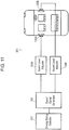
- Fig. 11 is a block diagram of conventional sound output device 501 disclosed in Patent Literature 1.
- Sound output device 501 includes driving-status detector 101, sound signal generator 102, sound level adjusters 104A and 104B, and speakers 105A and 105B connected to sound level adjusters 104A and 104B, respectively.
- sound signal generator 102 In response to the driving status of the vehicle detected by driving-status detector 101, sound signal generator 102 generates a simulated engine sound. The generated simulated engine sound is adjusted by sound level adjusters 104A and 104B, and output from speakers 105A and 105B.
- sound output device 501 By outputting the simulated engine sound, sound output device 501 emphasizes, to the driver of vehicle 106, the sound with which the number of rotations of the engine is changed by the operation of the accelerator, and enhances the operation sense of the driver of vehicle 106. Further, by mixing the simulated engine sound with an original engine sound, sound output device 501 creates an engine sound having comfortable frequency characteristics for the driver and improves the driving amenity of the driver.
- Fig. 11 components, such as driving-status detector 101, of sound output device 501, are shown outside vehicle 106. However, actually, these components are installed inside vehicle 106 similarly to speakers 105A and 105B.
- the simulated engine sound output from speakers 105A and 105B interferes with the sound reflected on an inside, such as wall surfaces, of vehicle 106, and produces a peak or a dip at a specific frequency of the output sound.
- passengers sitting at predetermined positions, such as a driver seat and a front passenger seat may not hear a desirable simulated engine sound.
- JP 5-80790 A describes the recording of a running sound of a vehicle and reproducing the sound in the vehicle's passenger compartment.
- a sinusoidal sound is synchronized with the rotation of the vehicle engine by employing an internal sine wave data table.
- a plurality of sinusoidal wave tables may be used to provide different phase characteristics for each speaker.
- Patent Literature 1 Japanese Patent Laid-Open Publication No. 02-15829 A sound output device is configured to be installed in a vehicle in accordance with claim 1.
- This sound output device allows a passenger at a predetermined position to hear the sound in a preferable condition.
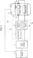
- Fig. 1 is a block diagram of sound output device 1001 according to an exemplary embodiment of the present invention.
- Sound output device 1001 includes driving-status detector 1, sound signal generator 2, phase shifter 3, sound level adjusters 4A and 4B, and speakers 6A and 6B.
- Phase shifter 3 and sound level adjuster 4A constitute unit 5A.
- Sound level adjuster 4B constitutes 5B.
- Speakers 6A and 6B are connected to units 5A and 5B, respectively.
- Sound output device 1001 is installed in vehicle 7.
- components, such as sound signal generator 2, of sound output device 1001 are shown outside vehicle 7. However, these components are installed in vehicle 7 similarly to speakers 6A and 6B.
- Speakers 6A and 6B are disposed on wall surfaces 7A and 7B, respectively, which face each other across vehicle cabin space 7C of vehicle 7. The speakers output a sound in directions opposed to each other.
- Speakers 6A and 6B are sound output parts each for outputting a simulated engine sound from sound output device 1001 to an inside of vehicle 7, and are disposed on a door of a front passenger seat and a door of a driver seat of vehicle 7, respectively. Speakers 6A and 6B output a sound signal output from units 5A and 5B, respectively, actually as a sound. Speakers 6A and 6B may be disposed on left and right doors of a rear seat of vehicle 7, respectively.
- Driving-status detector 1 detects a driving status, i.e. a status in which vehicle 7 is driven. Specifically, driving-status detector 1 detects a running status of vehicle 7, such as the number of rotations of the engine, information on the degree of opening of the accelerator, and the acceleration of the vehicle. Further, based on the detected running status, the driving-status detector estimates a load on the actual engine and a response status, and detects the driving status of vehicle 7.
- a driving status i.e. a status in which vehicle 7 is driven.
- driving-status detector 1 detects a running status of vehicle 7, such as the number of rotations of the engine, information on the degree of opening of the accelerator, and the acceleration of the vehicle. Further, based on the detected running status, the driving-status detector estimates a load on the actual engine and a response status, and detects the driving status of vehicle 7.
- sound signal generator 2 Based on the driving status of vehicle 7 detected by driving-status detector 1, sound signal generator 2 generates a reference waveform of a simulated engine sound most suitable for an operating status of the driver who is driving vehicle 7.
- Sound signal generator 2 has a table representing the correlation between the driving status of vehicle 7 and data of the simulated engine sound. The sound signal generator refers the table based on the detected driving status, to determine and generate the reference waveform of a simulated engine sound.
- the data of the simulated engine sound is stored in sound signal generator 2 as elements, such as the frequency characteristics of the level, the frequency characteristics of the phase, and the orders of higher harmonic waves included in the simulated engine sound.
- Sound signal generator 2 generates, as the reference waveform, sinusoidal waves that have frequencies of higher harmonic waves of the necessary orders. Alternatively, the sound signal generator generates non-sinusoidal waves, such as rectangular waves or triangular waves, including plural higher harmonic components.
- Sound level adjusters 4A and 4B in units 5A and 5B adjust the level of the reference waveform of the simulated engine sound generated in sound signal generator 2.
- phase shifter 3 is connected at the stage subsequent to sound signal generator 2.
- Sound output device 1001 of the embodiment includes two units 5A and 5B and two speakers 6A and 6B.
- the sound output device may have more than two units and speakers connected to these units.
- Phase shifter 3 shifts the phase of the reference waveform generated by sound signal generator 2, and causes unit 5A to output a sound signal that has a predetermined phase difference from the sound signal output from at least one unit, such as unit 5B, of the units other than unit 5A.
- the phase characteristic i.e. the amount of phase to be shifted by phase shifter 3 at each frequency, is a phase characteristic in response to the driving status of vehicle 7 detected by driving-status detector 1 in order to provide a simulated engine sound most suitable for the driving status of the driver.
- Sound level adjuster 4A adjusts a gain at each frequency such that the level of the sound signal output from phase shifter 3 has a predetermined frequency characteristic.
- sound level adjuster 4B adjusts a gain at each frequency such that the level of the sound signal generated in sound signal generator 2 has a predetermined frequency characteristic.
- the predetermined frequency characteristic is a frequency characteristic in response to the driving status of vehicle 7 detected by driving-status detector 1, similar to the phase characteristic in phase shifter 3.
- Driving-status detector 1 detects a current driving status of vehicle 7 cased on this signal.
- the driving status of the vehicle detected by driving-status detector 1 is output to sound signal generator 2 as a signal. Based on this signal, sound signal generator 2 generates a sound signal that causes speakers 6A and 6B to output a sound, such as a simulated engine sound.
- phase shifter 3 corrects the phase of the sound signal
- sound level adjuster 4A adjusts the level of the sound signal at each frequency.
- sound level adjuster 4B adjusts the level of the sound signal generated in sound signal generator 2, at each frequency.
- Unit 5B does not include phase shifter 3, and does not correct the phase of the sound signal.
- the signals output from units 5A and 5B are output from speakers 6A and 6B, as a sound, respectively.
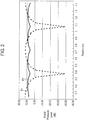
- Fig. 2 shows a relation between a position inside vehicle 7 having sound output device 1001 installed therein and a sound pressure of the simulated engine sound at a frequency of 250 Hz. That is, Fig. 2 shows a simulation model considering only acoustic interference where only reflection between wall surfaces 7A and 7B spaced apart from each by a distance of 1.4m.
- the vertical axis represents a sound pressure
- the horizontal axis shows a distance from wall surface 7A between wall surfaces 7A and 7B.
- Properties P1 show a sound pressure level of a comparative example of a sound output device which does not include phase shifter correcting the phase.
- Properties P2 show a sound pressure level of sound output device 1001 including phase shifter 2 correcting the phase into the opposite phase.
- the comparative example of the sound output device upon speakers 6A and 6B outputting sounds of sinusoidal waves in the same phase at 250 Hz, produces dips occur at positions of about 0.35m from wall surfaces 7A and 7B as shown by properties P1. If the front passenger seat and the driver seat are apart from wall surfaces 7A and 7B by a distance of 0.35m, respectively, the passengers sitting on the driver seat and the front passenger seat hardly hear the simulated engine sound, i.e. a sound at a frequency of 250 Hz, thus not being provided with a preferable simulated engine sound.
- the phase is corrected by phase shifter 3 such that the sound output from speaker 6A is opposite to the phase of the sound output from speaker 6B.
- This operation suppresses the influence of the acoustic interference inside vehicle 7, and reduces the dips significantly as shown by properties P2. As a result, the passengers can hear the sound at a frequency of 250 Hz without any problem.
- units 5A and 5B process the reference signal generated by sound signal generator 2.
- Speakers 6A and 6B as sound output parts output the reference signals processed in units 5A and 5B, respectively.
- Phase shifter 3 shifts the phase of the reference signal such that the reference signals output from speakers 6A and 6B have a phase difference between the signals.
- Phase shifter 3 shifts the phase of the sound signal in the simulated engine sound, i.e. a sound including higher harmonic waves of plural orders, by the amounts corresponding to plural frequencies. This can suppress the dips and peaks in predetermined positions (apart by 0.35m from wall surfaces 7A and 7B) inside vehicle 7. As a result, the passengers can hear the sound signal generated by sound signal generator 2, i.e. the simulated engine sound, in a preferable condition.
- Sound signal generator 2 stores discrete data of one cycle of the waveform of the reference signal in a data table.
- the reference signal has a waveform, such as a sinusoidal wave, a triangular wave, or a square wave, having regularity
- sound signal generator 2 can store data of at least 1/4 of the cycle of the waveform to generate the reference signal.
- the data table stores points at which one cycle of the reference signal is sampled by output sampling periods at which sound signal generator 2 outputs the reference signal, and also stores plural sampling values of the level obtained by the sampling at these points.
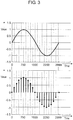
- Fig. 3 shows a waveform of a sinusoidal wave, i.e. the reference signal.
- Fig. 3 also shows the waveform as plural sampling values stored in the data table.
- the data table contains 3000 sampling values representing the waveform of one cycle of a sinusoidal wave as shown in Figs. 3 and 4 ,.
- the number of the sampling values of the waveform may exceed the number of the output sampling period.
- Sound signal generator 2 generates the reference signal by outputting sampling values from the data table by output sampling periods at intervals in response to the driving status detected by driving-status detector 1. For example, the 3000 sampling values representing one cycle of the sinusoidal wave at output sampling periods of 0.333 ms (3000 Hz) are stored in the data table. In this case, 3000 sampling values are extracted at intervals of 50 sampling values at sampling periods from the data table to generate a sinusoidal wave of 50Hz.
- Phase shifter 3 of unit 5A extracts, from the sampling values stored in the data table, sampling values at points that are apart from the points at which unit 5B extracts sampling values from the data table by the amount of the phase to be shifted. Thereby, a phase difference corresponding to the amount can be provided.
- Phase shifter 3 of unit 5A extracts, from the data table, sampling values at the points apart from the points of the sampling value output from sound signal generator 2 to unit 5B by target number TS corresponding to the amount of phase to be shifted. Thereby, a sound signal having a phase shifted relative to the sound signal output to unit 5B can be output.
- unit 5 shows a waveform generated when the phase of the sound output from speaker 6A is shifted relative to the sound output from speaker 6B e.g., by -n/2.
- Phase shifter 3 may store the amount of phase to be shifted, i.e. the maximum value of increment DTS of target number TS, every time one sampling value is extracted. In this case, phase shifter 3 can shift the phase of the sound signal by a predetermined amount by increasing target number TS by the maximum value of increment DTS every time one sampling value is extracted from the data table. Instead of storing the maximum value of increment DTS by which target number TS is increased every time one sampling value is extracted, phase shifter 3 may store the maximum value of increment DTS by which target number TS is increased every time plural sampling values is extracted.
- Fig. 6 shows a phase shifted by a phase shifter of a comparative example.
- the phase shifter of the comparative example shifts the phase by + ⁇ /2 from time point t1 to time point t2 which is a point after one sampling period.
- a steep phase shift for such a short period of time between time points t1 and t2 causes discontinuity of the sound signal, and thus generates an abnormal sound from speaker 6A.
- Fig. 7 shows a phase shifted by phase shifter 3 of sound output device 1001 according to the embodiment.
- Phase shifter 3 stores an initial value and the maximum value of increment DTS of the amount of the phase to be shifted in the plural sampling periods.
- phase shifter 3 stores zero 0 as the initial value, and the maximum value of increment DTS of the amount of shift corresponding to n/60 in twelve sampling periods.
- phase shifter 3 shifts the phase by ⁇ /2, the phase shifter increases the amount of shift from the initial value (0) by increments of n/60 during twelve sampling periods.
- unit 5A generates the reference signal by extracting plural sampling values at output sampling periods from the data table at intervals in response to the detected driving status.
- Unit 5B generates the reference signal by extracting plural sampling values at the output sampling periods from the data table at the intervals.
- Phase shifter 3 sets a point out of the plural points to be extracted by unit 5A such that the point is apart from the point to be extracted by unit 5B by a number corresponding to the phase in response to the detected driving status. Further, phase shifter 3 sets the point to be extracted by unit 5A apart from the point to be extracted by unit 5B by a number obtained by accumulating predetermined increment DTS at the output sampling periods toward target number TS.
- phase shifter 3 operates to accumulate predetermined increment DTS from the initial value until the number obtained by accumulating predetermined increment DTS from the initial value (0) at the output sampling periods reaches target number TS.
- Phase shifter 3 operates to set the point to be extracted by unit 5A apart from the point to be extracted by unit 5B by the number obtained by accumulating predetermined increment DTS from the initial value.
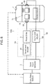
- Fig. 8 is a block diagram of another sound output device 1002 according to the embodiment.
- components identical to those of sound output device 1001 shown in Fig. 1 are denoted by the same reference numerals.
- phase shifter 3 is connected between sound level adjuster 4A and speaker 6A. Sound output device 1002 has the advantages similar to those of sound output device 1001.
- Fig. 9 is a block diagram of still another sound output device 1003 according to the embodiment.
- unit 5B further includes phase shifter 3B for shifting the phase of a sound signal generated by sound signal generator 2 similarly to that of phase shifter 3.
- Sound output device 1003 has the advantages similar to those of sound output device 1001.
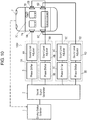
- Fig. 10 is a block diagram of yet another sound output device 1004 according to the embodiment.
- Sound output device 1004 further includes units 5C and 5D, and speakers 6C and 6D, i.e. sound output parts connected to units 5C and 5D, respectively, in addition to sound output device 1003 shown in Fig. 9 .
- Unit 5C includes sound level adjuster 4C for adjusting the level of the sound signal generated by sound signal generator 2 at each frequency, and phase shifter 3C for shifting the phase of the sound signal.
- Unit 5D includes sound level adjuster 4D for adjusting the level of the sound signal generated by sound signal generator 2 at each frequency, and phase shifter 3D for shifting the phase of the sound signal.
- Speaker 6C outputs a sound signal that has a level adjusted by sound level adjuster 4C and a phase shifted by phase shifter 3C to vehicle cabin space 7C.
- Speaker 6D outputs a sound signal that has a level adjusted by sound level adjuster 4D and a phase shifted by phase shifter 3D to vehicle cabin space 7C.
- Speakers 6C and 6D are disposed on left and right wall surfaces of the rear seat of vehicle 7 facing each other. Sound output device 1004 can further reduce the dips of the sound to be heard by the passengers on the front and rear seats of vehicle 7.
- a sound output device allows the passenger at a predetermined position to hear a sound in a preferable condition, and thus, is useful for various types of vehicles, such as an automobile.
Landscapes
- Health & Medical Sciences (AREA)
- General Health & Medical Sciences (AREA)
- Physics & Mathematics (AREA)
- Engineering & Computer Science (AREA)
- Acoustics & Sound (AREA)
- Audiology, Speech & Language Pathology (AREA)
- Multimedia (AREA)
- Otolaryngology (AREA)
- Signal Processing (AREA)
- Fittings On The Vehicle Exterior For Carrying Loads, And Devices For Holding Or Mounting Articles (AREA)
- Soundproofing, Sound Blocking, And Sound Damping (AREA)
Applications Claiming Priority (2)
| Application Number | Priority Date | Filing Date | Title |
|---|---|---|---|
| JP2008300498 | 2008-11-26 | ||
| PCT/JP2009/006302 WO2010061569A1 (ja) | 2008-11-26 | 2009-11-24 | 音声出力装置 |
Publications (3)
| Publication Number | Publication Date |
|---|---|
| EP2352143A1 EP2352143A1 (en) | 2011-08-03 |
| EP2352143A4 EP2352143A4 (en) | 2017-10-11 |
| EP2352143B1 true EP2352143B1 (en) | 2019-08-07 |
Family
ID=42225456
Family Applications (1)
| Application Number | Title | Priority Date | Filing Date |
|---|---|---|---|
| EP09828819.4A Active EP2352143B1 (en) | 2008-11-26 | 2009-11-24 | Sound output device |
Country Status (5)
| Country | Link |
|---|---|
| US (1) | US8798288B2 (zh) |
| EP (1) | EP2352143B1 (zh) |
| JP (1) | JP5541162B2 (zh) |
| CN (1) | CN102224541B (zh) |
| WO (1) | WO2010061569A1 (zh) |
Families Citing this family (7)
| Publication number | Priority date | Publication date | Assignee | Title |
|---|---|---|---|---|
| US8489275B2 (en) * | 2011-06-01 | 2013-07-16 | Toyota Motor Engineering & Manufacturing North America, Inc. | Methods for selective activation of multimedia functions and vehicles incorporating the same |
| US9031248B2 (en) * | 2013-01-18 | 2015-05-12 | Bose Corporation | Vehicle engine sound extraction and reproduction |
| US9959852B2 (en) | 2013-01-18 | 2018-05-01 | Bose Corporation | Vehicle engine sound extraction |
| US9469247B2 (en) * | 2013-11-21 | 2016-10-18 | Harman International Industries, Incorporated | Using external sounds to alert vehicle occupants of external events and mask in-car conversations |
| KR102139916B1 (ko) * | 2013-11-22 | 2020-07-31 | 현대모비스 주식회사 | 차량의 가상엔진음 생성 방법 |
| US20190266994A1 (en) * | 2016-06-15 | 2019-08-29 | Honda Motor Co., Ltd. | Active sound effect generation system |
| JP7523189B2 (ja) | 2021-03-30 | 2024-07-26 | パナソニックオートモーティブシステムズ株式会社 | 音声出力装置、及び、音声出力方法 |
Family Cites Families (15)
| Publication number | Priority date | Publication date | Assignee | Title |
|---|---|---|---|---|
| JPS6281197A (ja) | 1985-10-03 | 1987-04-14 | Nissan Motor Co Ltd | 音場改善装置 |
| JPH01151399A (ja) | 1987-12-08 | 1989-06-14 | Mitsubishi Electric Corp | 音響再生装置 |
| JP2803749B2 (ja) | 1988-12-12 | 1998-09-24 | マツダ株式会社 | 車室内エンジン音の制御装置 |
| JPH0422295A (ja) | 1990-05-16 | 1992-01-27 | Mitsubishi Electric Corp | 車載スピーカシステム |
| JPH0580790A (ja) * | 1991-09-21 | 1993-04-02 | Hitachi Ltd | 車室内音響制御装置 |
| JPH10224887A (ja) | 1997-02-06 | 1998-08-21 | Pioneer Electron Corp | 車載用スピーカシステム |
| JPH1151399A (ja) | 1997-08-01 | 1999-02-26 | Matsushita Electric Ind Co Ltd | ガスこんろ |
| JP4022295B2 (ja) * | 1997-11-12 | 2007-12-12 | エムケー精工株式会社 | オイル供給装置 |
| JP2003241767A (ja) * | 2002-02-14 | 2003-08-29 | Alpine Electronics Inc | ノイズキャンセル装置 |
| US7424430B2 (en) | 2003-01-30 | 2008-09-09 | Yamaha Corporation | Tone generator of wave table type with voice synthesis capability |
| JP3915704B2 (ja) | 2003-01-30 | 2007-05-16 | ヤマハ株式会社 | 音声合成装置 |
| JP4074612B2 (ja) * | 2004-09-14 | 2008-04-09 | 本田技研工業株式会社 | 能動型振動騒音制御装置 |
| JP4173891B2 (ja) | 2005-03-22 | 2008-10-29 | 本田技研工業株式会社 | 移動体用効果音発生装置 |
| JP2007208679A (ja) * | 2006-02-02 | 2007-08-16 | Matsushita Electric Ind Co Ltd | 音響再生装置 |
| JP5080790B2 (ja) * | 2006-11-24 | 2012-11-21 | 株式会社平和 | 遊技機 |
-
2009
- 2009-11-24 WO PCT/JP2009/006302 patent/WO2010061569A1/ja active Application Filing
- 2009-11-24 CN CN2009801472505A patent/CN102224541B/zh active Active
- 2009-11-24 EP EP09828819.4A patent/EP2352143B1/en active Active
- 2009-11-24 JP JP2010540341A patent/JP5541162B2/ja active Active
- 2009-11-24 US US13/128,651 patent/US8798288B2/en active Active
Non-Patent Citations (1)
| Title |
|---|
| None * |
Also Published As
| Publication number | Publication date |
|---|---|
| EP2352143A4 (en) | 2017-10-11 |
| WO2010061569A1 (ja) | 2010-06-03 |
| JP5541162B2 (ja) | 2014-07-09 |
| EP2352143A1 (en) | 2011-08-03 |
| US8798288B2 (en) | 2014-08-05 |
| JPWO2010061569A1 (ja) | 2012-04-26 |
| CN102224541B (zh) | 2013-09-18 |
| US20110211710A1 (en) | 2011-09-01 |
| CN102224541A (zh) | 2011-10-19 |
Similar Documents
| Publication | Publication Date | Title |
|---|---|---|
| EP2352143B1 (en) | Sound output device | |
| JP4378388B2 (ja) | 能動型効果音発生装置 | |
| EP1705644B1 (en) | Apparatus for producing sound effect in a motor vehicle | |
| EP1906384B1 (en) | Active noise reduction device | |
| US8027484B2 (en) | Active vibration noise controller | |
| US9454952B2 (en) | Systems and methods for controlling noise in a vehicle | |
| US9437185B2 (en) | Active sound effect generating apparatus | |
| JP5793445B2 (ja) | 車両用能動型効果音発生装置 | |
| US8041053B2 (en) | Vehicular sound effect generating apparatus | |
| US20070140503A1 (en) | Active vibrational noise control apparatus | |
| CN107801130B (zh) | 用于车辆的声音控制装置及其控制方法 | |
| EP2600341A2 (en) | Active vibration noise control apparatus | |
| CN104908688A (zh) | 车辆主动降噪的方法及装置 | |
| US8150055B2 (en) | Active noise control system and active vibration control system | |
| US9050925B2 (en) | Vehicle having an electric drive | |
| EP2782093A2 (en) | Vehicular active vibrational noise control apparatus | |
| JP2827374B2 (ja) | 能動型騒音制御装置 | |
| JP2003195951A (ja) | 能動型振動制御装置、車両用能動型振動制御装置 | |
| JP3293922B2 (ja) | 能動型騒音制御装置 | |
| JP4110783B2 (ja) | 騒音制御装置 | |
| Pietrzyk | Dispersion of Test-Based NVH Characteristics at Various Trim Levels | |
| CN118230706A (zh) | 提供快速作用的发动机阶次噪声消除的设备、系统和方法 | |
| JPH0635483A (ja) | 騒音キャンセル方式 | |
| JPH05210392A (ja) | 車両用騒音制御装置 | |
| Misol et al. | Reduction of broadband noise in vehicles by means of active feedforward control |
Legal Events
| Date | Code | Title | Description |
|---|---|---|---|
| PUAI | Public reference made under article 153(3) epc to a published international application that has entered the european phase |
Free format text: ORIGINAL CODE: 0009012 |
|
| 17P | Request for examination filed |
Effective date: 20110520 |
|
| AK | Designated contracting states |
Kind code of ref document: A1 Designated state(s): AT BE BG CH CY CZ DE DK EE ES FI FR GB GR HR HU IE IS IT LI LT LU LV MC MK MT NL NO PL PT RO SE SI SK SM TR |
|
| DAX | Request for extension of the european patent (deleted) | ||
| RAP1 | Party data changed (applicant data changed or rights of an application transferred) |
Owner name: PANASONIC INTELLECTUAL PROPERTY MANAGEMENT CO., LT |
|
| RAP1 | Party data changed (applicant data changed or rights of an application transferred) |
Owner name: PANASONIC INTELLECTUAL PROPERTY MANAGEMENT CO., LT |
|
| REG | Reference to a national code |
Ref country code: DE Ref legal event code: R079 Ref document number: 602009059397 Country of ref document: DE Free format text: PREVIOUS MAIN CLASS: G10K0015040000 Ipc: G10K0015020000 |
|
| RA4 | Supplementary search report drawn up and despatched (corrected) |
Effective date: 20170911 |
|
| RIC1 | Information provided on ipc code assigned before grant |
Ipc: H04R 3/12 20060101ALI20170905BHEP Ipc: G10K 15/02 20060101AFI20170905BHEP |
|
| GRAP | Despatch of communication of intention to grant a patent |
Free format text: ORIGINAL CODE: EPIDOSNIGR1 |
|
| STAA | Information on the status of an ep patent application or granted ep patent |
Free format text: STATUS: GRANT OF PATENT IS INTENDED |
|
| INTG | Intention to grant announced |
Effective date: 20190313 |
|
| GRAS | Grant fee paid |
Free format text: ORIGINAL CODE: EPIDOSNIGR3 |
|
| GRAA | (expected) grant |
Free format text: ORIGINAL CODE: 0009210 |
|
| STAA | Information on the status of an ep patent application or granted ep patent |
Free format text: STATUS: THE PATENT HAS BEEN GRANTED |
|
| AK | Designated contracting states |
Kind code of ref document: B1 Designated state(s): AT BE BG CH CY CZ DE DK EE ES FI FR GB GR HR HU IE IS IT LI LT LU LV MC MK MT NL NO PL PT RO SE SI SK SM TR |
|
| REG | Reference to a national code |
Ref country code: GB Ref legal event code: FG4D |
|
| REG | Reference to a national code |
Ref country code: CH Ref legal event code: EP Ref country code: AT Ref legal event code: REF Ref document number: 1165057 Country of ref document: AT Kind code of ref document: T Effective date: 20190815 |
|
| REG | Reference to a national code |
Ref country code: DE Ref legal event code: R096 Ref document number: 602009059397 Country of ref document: DE |
|
| REG | Reference to a national code |
Ref country code: IE Ref legal event code: FG4D |
|
| REG | Reference to a national code |
Ref country code: NL Ref legal event code: MP Effective date: 20190807 |
|
| REG | Reference to a national code |
Ref country code: LT Ref legal event code: MG4D |
|
| PG25 | Lapsed in a contracting state [announced via postgrant information from national office to epo] |
Ref country code: FI Free format text: LAPSE BECAUSE OF FAILURE TO SUBMIT A TRANSLATION OF THE DESCRIPTION OR TO PAY THE FEE WITHIN THE PRESCRIBED TIME-LIMIT Effective date: 20190807 Ref country code: SE Free format text: LAPSE BECAUSE OF FAILURE TO SUBMIT A TRANSLATION OF THE DESCRIPTION OR TO PAY THE FEE WITHIN THE PRESCRIBED TIME-LIMIT Effective date: 20190807 Ref country code: HR Free format text: LAPSE BECAUSE OF FAILURE TO SUBMIT A TRANSLATION OF THE DESCRIPTION OR TO PAY THE FEE WITHIN THE PRESCRIBED TIME-LIMIT Effective date: 20190807 Ref country code: PT Free format text: LAPSE BECAUSE OF FAILURE TO SUBMIT A TRANSLATION OF THE DESCRIPTION OR TO PAY THE FEE WITHIN THE PRESCRIBED TIME-LIMIT Effective date: 20191209 Ref country code: NO Free format text: LAPSE BECAUSE OF FAILURE TO SUBMIT A TRANSLATION OF THE DESCRIPTION OR TO PAY THE FEE WITHIN THE PRESCRIBED TIME-LIMIT Effective date: 20191107 Ref country code: LT Free format text: LAPSE BECAUSE OF FAILURE TO SUBMIT A TRANSLATION OF THE DESCRIPTION OR TO PAY THE FEE WITHIN THE PRESCRIBED TIME-LIMIT Effective date: 20190807 Ref country code: NL Free format text: LAPSE BECAUSE OF FAILURE TO SUBMIT A TRANSLATION OF THE DESCRIPTION OR TO PAY THE FEE WITHIN THE PRESCRIBED TIME-LIMIT Effective date: 20190807 Ref country code: BG Free format text: LAPSE BECAUSE OF FAILURE TO SUBMIT A TRANSLATION OF THE DESCRIPTION OR TO PAY THE FEE WITHIN THE PRESCRIBED TIME-LIMIT Effective date: 20191107 |
|
| REG | Reference to a national code |
Ref country code: AT Ref legal event code: MK05 Ref document number: 1165057 Country of ref document: AT Kind code of ref document: T Effective date: 20190807 |
|
| PG25 | Lapsed in a contracting state [announced via postgrant information from national office to epo] |
Ref country code: GR Free format text: LAPSE BECAUSE OF FAILURE TO SUBMIT A TRANSLATION OF THE DESCRIPTION OR TO PAY THE FEE WITHIN THE PRESCRIBED TIME-LIMIT Effective date: 20191108 Ref country code: LV Free format text: LAPSE BECAUSE OF FAILURE TO SUBMIT A TRANSLATION OF THE DESCRIPTION OR TO PAY THE FEE WITHIN THE PRESCRIBED TIME-LIMIT Effective date: 20190807 Ref country code: ES Free format text: LAPSE BECAUSE OF FAILURE TO SUBMIT A TRANSLATION OF THE DESCRIPTION OR TO PAY THE FEE WITHIN THE PRESCRIBED TIME-LIMIT Effective date: 20190807 Ref country code: IS Free format text: LAPSE BECAUSE OF FAILURE TO SUBMIT A TRANSLATION OF THE DESCRIPTION OR TO PAY THE FEE WITHIN THE PRESCRIBED TIME-LIMIT Effective date: 20191207 |
|
| PG25 | Lapsed in a contracting state [announced via postgrant information from national office to epo] |
Ref country code: TR Free format text: LAPSE BECAUSE OF FAILURE TO SUBMIT A TRANSLATION OF THE DESCRIPTION OR TO PAY THE FEE WITHIN THE PRESCRIBED TIME-LIMIT Effective date: 20190807 |
|
| PG25 | Lapsed in a contracting state [announced via postgrant information from national office to epo] |
Ref country code: RO Free format text: LAPSE BECAUSE OF FAILURE TO SUBMIT A TRANSLATION OF THE DESCRIPTION OR TO PAY THE FEE WITHIN THE PRESCRIBED TIME-LIMIT Effective date: 20190807 Ref country code: PL Free format text: LAPSE BECAUSE OF FAILURE TO SUBMIT A TRANSLATION OF THE DESCRIPTION OR TO PAY THE FEE WITHIN THE PRESCRIBED TIME-LIMIT Effective date: 20190807 Ref country code: AT Free format text: LAPSE BECAUSE OF FAILURE TO SUBMIT A TRANSLATION OF THE DESCRIPTION OR TO PAY THE FEE WITHIN THE PRESCRIBED TIME-LIMIT Effective date: 20190807 Ref country code: EE Free format text: LAPSE BECAUSE OF FAILURE TO SUBMIT A TRANSLATION OF THE DESCRIPTION OR TO PAY THE FEE WITHIN THE PRESCRIBED TIME-LIMIT Effective date: 20190807 Ref country code: IT Free format text: LAPSE BECAUSE OF FAILURE TO SUBMIT A TRANSLATION OF THE DESCRIPTION OR TO PAY THE FEE WITHIN THE PRESCRIBED TIME-LIMIT Effective date: 20190807 Ref country code: DK Free format text: LAPSE BECAUSE OF FAILURE TO SUBMIT A TRANSLATION OF THE DESCRIPTION OR TO PAY THE FEE WITHIN THE PRESCRIBED TIME-LIMIT Effective date: 20190807 |
|
| PG25 | Lapsed in a contracting state [announced via postgrant information from national office to epo] |
Ref country code: SK Free format text: LAPSE BECAUSE OF FAILURE TO SUBMIT A TRANSLATION OF THE DESCRIPTION OR TO PAY THE FEE WITHIN THE PRESCRIBED TIME-LIMIT Effective date: 20190807 Ref country code: CZ Free format text: LAPSE BECAUSE OF FAILURE TO SUBMIT A TRANSLATION OF THE DESCRIPTION OR TO PAY THE FEE WITHIN THE PRESCRIBED TIME-LIMIT Effective date: 20190807 Ref country code: SM Free format text: LAPSE BECAUSE OF FAILURE TO SUBMIT A TRANSLATION OF THE DESCRIPTION OR TO PAY THE FEE WITHIN THE PRESCRIBED TIME-LIMIT Effective date: 20190807 Ref country code: IS Free format text: LAPSE BECAUSE OF FAILURE TO SUBMIT A TRANSLATION OF THE DESCRIPTION OR TO PAY THE FEE WITHIN THE PRESCRIBED TIME-LIMIT Effective date: 20200224 |
|
| REG | Reference to a national code |
Ref country code: DE Ref legal event code: R097 Ref document number: 602009059397 Country of ref document: DE |
|
| REG | Reference to a national code |
Ref country code: CH Ref legal event code: PL |
|
| PLBE | No opposition filed within time limit |
Free format text: ORIGINAL CODE: 0009261 |
|
| STAA | Information on the status of an ep patent application or granted ep patent |
Free format text: STATUS: NO OPPOSITION FILED WITHIN TIME LIMIT |
|
| PG2D | Information on lapse in contracting state deleted |
Ref country code: IS |
|
| PG25 | Lapsed in a contracting state [announced via postgrant information from national office to epo] |
Ref country code: MC Free format text: LAPSE BECAUSE OF FAILURE TO SUBMIT A TRANSLATION OF THE DESCRIPTION OR TO PAY THE FEE WITHIN THE PRESCRIBED TIME-LIMIT Effective date: 20190807 Ref country code: LI Free format text: LAPSE BECAUSE OF NON-PAYMENT OF DUE FEES Effective date: 20191130 Ref country code: LU Free format text: LAPSE BECAUSE OF NON-PAYMENT OF DUE FEES Effective date: 20191124 Ref country code: CH Free format text: LAPSE BECAUSE OF NON-PAYMENT OF DUE FEES Effective date: 20191130 |
|
| 26N | No opposition filed |
Effective date: 20200603 |
|
| REG | Reference to a national code |
Ref country code: BE Ref legal event code: MM Effective date: 20191130 |
|
| PG25 | Lapsed in a contracting state [announced via postgrant information from national office to epo] |
Ref country code: SI Free format text: LAPSE BECAUSE OF FAILURE TO SUBMIT A TRANSLATION OF THE DESCRIPTION OR TO PAY THE FEE WITHIN THE PRESCRIBED TIME-LIMIT Effective date: 20190807 |
|
| GBPC | Gb: european patent ceased through non-payment of renewal fee |
Effective date: 20191124 |
|
| PG25 | Lapsed in a contracting state [announced via postgrant information from national office to epo] |
Ref country code: IE Free format text: LAPSE BECAUSE OF NON-PAYMENT OF DUE FEES Effective date: 20191124 Ref country code: GB Free format text: LAPSE BECAUSE OF NON-PAYMENT OF DUE FEES Effective date: 20191124 Ref country code: FR Free format text: LAPSE BECAUSE OF NON-PAYMENT OF DUE FEES Effective date: 20191130 |
|
| PG25 | Lapsed in a contracting state [announced via postgrant information from national office to epo] |
Ref country code: BE Free format text: LAPSE BECAUSE OF NON-PAYMENT OF DUE FEES Effective date: 20191130 |
|
| PG25 | Lapsed in a contracting state [announced via postgrant information from national office to epo] |
Ref country code: CY Free format text: LAPSE BECAUSE OF FAILURE TO SUBMIT A TRANSLATION OF THE DESCRIPTION OR TO PAY THE FEE WITHIN THE PRESCRIBED TIME-LIMIT Effective date: 20190807 |
|
| PG25 | Lapsed in a contracting state [announced via postgrant information from national office to epo] |
Ref country code: HU Free format text: LAPSE BECAUSE OF FAILURE TO SUBMIT A TRANSLATION OF THE DESCRIPTION OR TO PAY THE FEE WITHIN THE PRESCRIBED TIME-LIMIT; INVALID AB INITIO Effective date: 20091124 Ref country code: MT Free format text: LAPSE BECAUSE OF FAILURE TO SUBMIT A TRANSLATION OF THE DESCRIPTION OR TO PAY THE FEE WITHIN THE PRESCRIBED TIME-LIMIT Effective date: 20190807 |
|
| PG25 | Lapsed in a contracting state [announced via postgrant information from national office to epo] |
Ref country code: MK Free format text: LAPSE BECAUSE OF FAILURE TO SUBMIT A TRANSLATION OF THE DESCRIPTION OR TO PAY THE FEE WITHIN THE PRESCRIBED TIME-LIMIT Effective date: 20190807 |
|
| PGFP | Annual fee paid to national office [announced via postgrant information from national office to epo] |
Ref country code: DE Payment date: 20231121 Year of fee payment: 15 |
|
| REG | Reference to a national code |
Ref country code: DE Ref legal event code: R081 Ref document number: 602009059397 Country of ref document: DE Owner name: PANASONIC AUTOMOTIVE SYSTEMS CO., LTD., YOKOHA, JP Free format text: FORMER OWNER: PANASONIC INTELLECTUAL PROPERTY MANAGEMENT CO., LTD, OSAKA-SHI, OSAKA, JP |