US8798288B2 - Voice output device - Google Patents
Voice output device Download PDFInfo
- Publication number
- US8798288B2 US8798288B2 US13/128,651 US200913128651A US8798288B2 US 8798288 B2 US8798288 B2 US 8798288B2 US 200913128651 A US200913128651 A US 200913128651A US 8798288 B2 US8798288 B2 US 8798288B2
- Authority
- US
- United States
- Prior art keywords
- sound
- sound output
- reference signal
- phase
- output device
- Prior art date
- Legal status (The legal status is an assumption and is not a legal conclusion. Google has not performed a legal analysis and makes no representation as to the accuracy of the status listed.)
- Active, expires
Links
Images


Classifications
-
- G—PHYSICS
- G10—MUSICAL INSTRUMENTS; ACOUSTICS
- G10K—SOUND-PRODUCING DEVICES; METHODS OR DEVICES FOR PROTECTING AGAINST, OR FOR DAMPING, NOISE OR OTHER ACOUSTIC WAVES IN GENERAL; ACOUSTICS NOT OTHERWISE PROVIDED FOR
- G10K15/00—Acoustics not otherwise provided for
- G10K15/02—Synthesis of acoustic waves
-
- H—ELECTRICITY
- H04—ELECTRIC COMMUNICATION TECHNIQUE
- H04R—LOUDSPEAKERS, MICROPHONES, GRAMOPHONE PICK-UPS OR LIKE ACOUSTIC ELECTROMECHANICAL TRANSDUCERS; DEAF-AID SETS; PUBLIC ADDRESS SYSTEMS
- H04R3/00—Circuits for transducers, loudspeakers or microphones
- H04R3/12—Circuits for transducers, loudspeakers or microphones for distributing signals to two or more loudspeakers
-
- H—ELECTRICITY
- H04—ELECTRIC COMMUNICATION TECHNIQUE
- H04R—LOUDSPEAKERS, MICROPHONES, GRAMOPHONE PICK-UPS OR LIKE ACOUSTIC ELECTROMECHANICAL TRANSDUCERS; DEAF-AID SETS; PUBLIC ADDRESS SYSTEMS
- H04R2499/00—Aspects covered by H04R or H04S not otherwise provided for in their subgroups
- H04R2499/10—General applications
- H04R2499/13—Acoustic transducers and sound field adaptation in vehicles
-
- H—ELECTRICITY
- H04—ELECTRIC COMMUNICATION TECHNIQUE
- H04R—LOUDSPEAKERS, MICROPHONES, GRAMOPHONE PICK-UPS OR LIKE ACOUSTIC ELECTROMECHANICAL TRANSDUCERS; DEAF-AID SETS; PUBLIC ADDRESS SYSTEMS
- H04R3/00—Circuits for transducers, loudspeakers or microphones
- H04R3/04—Circuits for transducers, loudspeakers or microphones for correcting frequency response
Definitions
- the present invention relates to a sound output device for outputting sounds, such as simulated engine sounds, in a vehicle, such as an automobile.
- FIG. 11 is a block diagram of conventional sound output device 501 disclosed in Patent Literature 1.
- Sound output device 501 includes driving-status detector 101 , sound signal generator 102 , sound level adjusters 104 A and 104 B, and speakers 105 A and 105 B connected to sound level adjusters 104 A and 104 B, respectively.
- sound signal generator 102 In response to the driving status of the vehicle detected by driving-status detector 101 , sound signal generator 102 generates a simulated engine sound. The generated simulated engine sound is adjusted by sound level adjusters 104 A and 104 B, and output from speakers 105 A and 105 B.
- sound output device 501 By outputting the simulated engine sound, sound output device 501 emphasizes, to the driver of vehicle 106 , the sound with which the number of rotations of the engine is changed by the operation of the accelerator, and enhances the operation sense of the driver of vehicle 106 . Further, by mixing the simulated engine sound with an original engine sound, sound output device 501 creates an engine sound having comfortable frequency characteristics for the driver and improves the driving amenity of the driver.
- components such as driving-status detector 101 , of sound output device 501 , are shown outside vehicle 106 . However, actually, these components are installed inside vehicle 106 similarly to speakers 105 A and 105 B.
- the simulated engine sound output from speakers 105 A and 105 B interferes with the sound reflected on an inside, such as wall surfaces, of vehicle 106 , and produces a peak or a dip at a specific frequency of the output sound.
- passengers sitting at predetermined positions, such as a driver seat and a front passenger seat may not hear a desirable simulated engine sound.
- a sound output device is configured to be installed in a vehicle.
- the sound output device includes a driving-status detector for detecting a driving status of the vehicle, a sound signal generator for generating a reference signal in response to the detected driving status, first and second units for processing the generated reference signal, first and second sound output parts for outputting the reference signals processed by the first and second units.
- the first unit includes a phase shifter for shifting a phase of the reference signal such that the reference signals output from the first sound output part and the second sound output part have a phase difference between the respective reference signals.
- This sound output device allows a passenger at a predetermined position to hear the sound in a preferable condition.
- FIG. 1 is a block diagram of a sound output device according to an exemplary embodiment of the present invention.
- FIG. 2 shows a relation between a position inside a vehicle where the sound output device is disposed and a sound pressure according to the embodiment.
- FIG. 3 shows data of a waveform of a reference signal stored in the sound output device according to the embodiment.
- FIG. 4 shows a data table representing the data shown in FIG. 3 .
- FIG. 5 shows an operation of a phase shifter of the sound output device according to the embodiment.
- FIG. 6 shows a phase shifted by a phase shifter of a comparative example of a sound output device.
- FIG. 7 shows a phase shifted by the phase shifter of the sound output device according to the embodiment.
- FIG. 8 is a block diagram of another sound output device according to the embodiment.
- FIG. 9 is a block diagram of still another sound output device according to the embodiment.
- FIG. 10 is a block diagram of yet another sound output device according to the embodiment.
- FIG. 11 is a block diagram of a conventional sound output device.
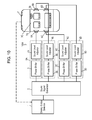
- FIG. 1 is a block diagram of sound output device 1001 according to an exemplary embodiment of the present invention.
- Sound output device 1001 includes driving-status detector 1 , sound signal generator 2 , phase shifter 3 , sound level adjusters 4 A and 4 B, and speakers 6 A and 6 B.
- Phase shifter 3 and sound level adjuster 4 A constitute unit 5 A.
- Sound level adjuster 4 B constitutes 5 B.
- Speakers 6 A and 6 B are connected to units 5 A and 5 B, respectively.
- Sound output device 1001 is installed in vehicle 7 .
- components, such as sound signal generator 2 , of sound output device 1001 are shown outside vehicle 7 . However, these components are installed in vehicle 7 similarly to speakers 6 A and 6 B.
- Speakers 6 A and 6 B are disposed on wall surfaces 7 A and 7 B, respectively, which face each other across vehicle cabin space 7 C of vehicle 7 . The speakers output a sound in directions opposed to each other.
- Speakers 6 A and 6 B are sound output parts each for outputting a simulated engine sound from sound output device 1001 to an inside of vehicle 7 , and are disposed on a door of a front passenger seat and a door of a driver seat of vehicle 7 , respectively. Speakers 6 A and 6 B output a sound signal output from units 5 A and 5 B, respectively, actually as a sound. Speakers 6 A and 6 B may be disposed on left and right doors of a rear seat of vehicle 7 , respectively.
- Driving-status detector 1 detects a driving status, i.e. a status in which vehicle 7 is driven. Specifically, driving-status detector 1 detects a running status of vehicle 7 , such as the number of rotations of the engine, information on the degree of opening of the accelerator, and the acceleration of the vehicle. Further, based on the detected running status, the driving-status detector estimates a load on the actual engine and a response status, and detects the driving status of vehicle 7 .
- a driving status i.e. a status in which vehicle 7 is driven.
- driving-status detector 1 detects a running status of vehicle 7 , such as the number of rotations of the engine, information on the degree of opening of the accelerator, and the acceleration of the vehicle. Further, based on the detected running status, the driving-status detector estimates a load on the actual engine and a response status, and detects the driving status of vehicle 7 .
- sound signal generator 2 Based on the driving status of vehicle 7 detected by driving-status detector 1 , sound signal generator 2 generates a reference waveform of a simulated engine sound most suitable for an operating status of the driver who is driving vehicle 7 .
- Sound signal generator 2 has a table representing the correlation between the driving status of vehicle 7 and data of the simulated engine sound. The sound signal generator refers the table based on the detected driving status, to determine and generate the reference waveform of a simulated engine sound.
- the data of the simulated engine sound is stored in sound signal generator 2 as elements, such as the frequency characteristics of the level, the frequency characteristics of the phase, and the orders of higher harmonic waves included in the simulated engine sound. Sound signal generator 2 generates, as the reference waveform, sinusoidal waves that have frequencies of higher harmonic waves of the necessary orders. Alternatively, the sound signal generator generates non-sinusoidal waves, such as rectangular waves or triangular waves, including plural higher harmonic components.
- Sound level adjusters 4 A and 4 B in units 5 A and 5 B adjust the level of the reference waveform of the simulated engine sound generated in sound signal generator 2 .
- phase shifter 3 is connected at the stage subsequent to sound signal generator 2 .
- Sound output device 1001 of the embodiment includes two units 5 A and 5 B and two speakers 6 A and 6 B.
- the sound output device may have more than two units and speakers connected to these units.
- Phase shifter 3 shifts the phase of the reference waveform generated by sound signal generator 2 , and causes unit 5 A to output a sound signal that has a predetermined phase difference from the sound signal output from at least one unit, such as unit 5 B, of the units other than unit 5 A.
- the phase characteristic i.e. the amount of phase to be shifted by phase shifter 3 at each frequency, is a phase characteristic in response to the driving status of vehicle 7 detected by driving-status detector 1 in order to provide a simulated engine sound most suitable for the driving status of the driver.
- Sound level adjuster 4 A adjusts a gain at each frequency such that the level of the sound signal output from phase shifter 3 has a predetermined frequency characteristic.
- sound level adjuster 4 B adjusts a gain at each frequency such that the level of the sound signal generated in sound signal generator 2 has a predetermined frequency characteristic.
- the predetermined frequency characteristic is a frequency characteristic in response to the driving status of vehicle 7 detected by driving-status detector 1 , similar to the phase characteristic in phase shifter 3 .
- Driving-status detector 1 detects a current driving status of vehicle 7 cased on this signal.
- the driving status of the vehicle detected by driving-status detector 1 is output to sound signal generator 2 as a signal. Based on this signal, sound signal generator 2 generates a sound signal that causes speakers 6 A and 6 B to output a sound, such as a simulated engine sound.
- phase shifter 3 corrects the phase of the sound signal
- sound level adjuster 4 A adjusts the level of the sound signal at each frequency.
- sound level adjuster 4 B adjusts the level of the sound signal generated in sound signal generator 2 , at each frequency.
- Unit 5 B does not include phase shifter 3 , and does not correct the phase of the sound signal.
- the signals output from units 5 A and 5 B are output from speakers 6 A and 6 B, as a sound, respectively.
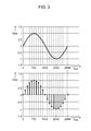
- FIG. 2 shows a relation between a position inside vehicle 7 having sound output device 1001 installed therein and a sound pressure of the simulated engine sound at a frequency of 250 Hz. That is, FIG. 2 shows a simulation model considering only acoustic interference where only reflection between wall surfaces 7 A and 7 B spaced apart from each by a distance of 1.4 m.
- the vertical axis represents a sound pressure
- the horizontal axis shows a distance from wall surface 7 A between wall surfaces 7 A and 7 B.
- Properties P 1 show a sound pressure level of a comparative example of a sound output device which does not include phase shifter correcting the phase.
- Properties P 2 show a sound pressure level of sound output device 1001 including phase shifter 2 correcting the phase into the opposite phase.
- the comparative example of the sound output device upon speakers 6 A and 6 B outputting sounds of sinusoidal waves in the same phase at 250 Hz, produces dips occur at positions of about 0.35 m from wall surfaces 7 A and 7 B as shown by properties P 1 . If the front passenger seat and the driver seat are apart from wall surfaces 7 A and 7 B by a distance of 0.35 m, respectively, the passengers sitting on the driver seat and the front passenger seat hardly hear the simulated engine sound, i.e. a sound at a frequency of 250 Hz, thus not being provided with a preferable simulated engine sound.
- the phase is corrected by phase shifter 3 such that the sound output from speaker 6 A is opposite to the phase of the sound output from speaker 6 B.
- This operation suppresses the influence of the acoustic interference inside vehicle 7 , and reduces the dips significantly as shown by properties P 2 . As a result, the passengers can hear the sound at a frequency of 250 Hz without any problem.
- units 5 A and 5 B process the reference signal generated by sound signal generator 2 .
- Speakers 6 A and 6 B as sound output parts output the reference signals processed in units 5 A and 5 B, respectively.
- Phase shifter 3 shifts the phase of the reference signal such that the reference signals output from speakers 6 A and 6 B have a phase difference between the signals.
- Phase shifter 3 shifts the phase of the sound signal in the simulated engine sound, i.e. a sound including higher harmonic waves of plural orders, by the amounts corresponding to plural frequencies. This can suppress the dips and peaks in predetermined positions (apart by 0.35 m from wall surfaces 7 A and 7 B) inside vehicle 7 . As a result, the passengers can hear the sound signal generated by sound signal generator 2 , i.e. the simulated engine sound, in a preferable condition.
- Sound signal generator 2 stores discrete data of one cycle of the waveform of the reference signal in a data table.
- the reference signal has a waveform, such as a sinusoidal wave, a triangular wave, or a square wave, having regularity
- sound signal generator 2 can store data of at least 1 ⁇ 4 of the cycle of the waveform to generate the reference signal.
- the data table stores points at which one cycle of the reference signal is sampled by output sampling periods at which sound signal generator 2 outputs the reference signal, and also stores plural sampling values of the level obtained by the sampling at these points.
- FIG. 3 shows a waveform of a sinusoidal wave, i.e. the reference signal.
- FIG. 3 also shows the waveform as plural sampling values stored in the data table.
- the data table contains 3000 sampling values representing the waveform of one cycle of a sinusoidal wave as shown in FIGS. 3 and 4 .
- the number of the sampling values of the waveform may exceed the number of the output sampling period.
- Sound signal generator 2 generates the reference signal by outputting sampling values from the data table by output sampling periods at intervals in response to the driving status detected by driving-status detector 1 .
- the 3000 sampling values representing one cycle of the sinusoidal wave at output sampling periods of 0.333 ms (3000 Hz) are stored in the data table.
- 3000 sampling values are extracted at intervals of 50 sampling values at sampling periods from the data table to generate a sinusoidal wave of 50 Hz.
- Phase shifter 3 of unit 5 A extracts, from the sampling values stored in the data table, sampling values at points that are apart from the points at which unit 5 B extracts sampling values from the data table by the amount of the phase to be shifted. Thereby, a phase difference corresponding to the amount can be provided.
- Phase shifter 3 of unit 5 A extracts, from the data table, sampling values at the points apart from the points of the sampling value output from sound signal generator 2 to unit 5 B by target number TS corresponding to the amount of phase to be shifted. Thereby, a sound signal having a phase shifted relative to the sound signal output to unit 5 B can be output.
- unit 5 shows a waveform generated when the phase of the sound output from speaker 6 A is shifted relative to the sound output from speaker 6 B e.g., by ⁇ /2.
- Phase shifter 3 may store the amount of phase to be shifted, i.e. the maximum value of increment DTS of target number TS, every time one sampling value is extracted. In this case, phase shifter 3 can shift the phase of the sound signal by a predetermined amount by increasing target number TS by the maximum value of increment DTS every time one sampling value is extracted from the data table. Instead of storing the maximum value of increment DTS by which target number TS is increased every time one sampling value is extracted, phase shifter 3 may store the maximum value of increment DTS by which target number TS is increased every time plural sampling values is extracted.
- FIG. 6 shows a phase shifted by a phase shifter of a comparative example.
- the phase shifter of the comparative example shifts the phase by + ⁇ /2 from time point t 1 to time point t 2 which is a point after one sampling period.
- a steep phase shift for such a short period of time between time points t 1 and t 2 causes discontinuity of the sound signal, and thus generates an abnormal sound from speaker 6 A.
- FIG. 7 shows a phase shifted by phase shifter 3 of sound output device 1001 according to the embodiment.
- Phase shifter 3 stores an initial value and the maximum value of increment DTS of the amount of the phase to be shifted in the plural sampling periods.
- phase shifter 3 stores zero 0 as the initial value, and the maximum value of increment DTS of the amount of shift corresponding to ⁇ /60 in twelve sampling periods.
- phase shifter 3 shifts the phase by ⁇ /2, the phase shifter increases the amount of shift from the initial value (0) by increments of ⁇ /60 during twelve sampling periods.
- unit 5 A generates the reference signal by extracting plural sampling values at output sampling periods from the data table at intervals in response to the detected driving status.
- Unit 5 B generates the reference signal by extracting plural sampling values at the output sampling periods from the data table at the intervals.
- Phase shifter 3 sets a point out of the plural points to be extracted by unit 5 A such that the point is apart from the point to be extracted by unit 5 B by a number corresponding to the phase in response to the detected driving status. Further, phase shifter 3 sets the point to be extracted by unit 5 A apart from the point to be extracted by unit 5 B by a number obtained by accumulating predetermined increment DTS at the output sampling periods toward target number TS.
- phase shifter 3 operates to accumulate predetermined increment DTS from the initial value until the number obtained by accumulating predetermined increment DTS from the initial value (0) at the output sampling periods reaches target number TS.
- Phase shifter 3 operates to set the point to be extracted by unit 5 A apart from the point to be extracted by unit 5 B by the number obtained by accumulating predetermined increment DTS from the initial value.
- FIG. 8 is a block diagram of another sound output device 1002 according to the embodiment.
- components identical to those of sound output device 1001 shown in FIG. 1 are denoted by the same reference numerals.
- phase shifter 3 is connected between sound level adjuster 4 A and speaker 6 A. Sound output device 1002 has the advantages similar to those of sound output device 1001 .
- FIG. 9 is a block diagram of still another sound output device 1003 according to the embodiment.
- unit 5 B further includes phase shifter 3 B for shifting the phase of a sound signal generated by sound signal generator 2 similarly to that of phase shifter 3 .
- Sound output device 1003 has the advantages similar to those of sound output device 1001 .
- FIG. 10 is a block diagram of yet another sound output device 1004 according to the embodiment.
- Sound output device 1004 further includes units 5 C and 5 D, and speakers 6 C and 6 D, i.e. sound output parts connected to units 5 C and 5 D, respectively, in addition to sound output device 1003 shown in FIG. 9 .
- Unit 5 C includes sound level adjuster 4 C for adjusting the level of the sound signal generated by sound signal generator 2 at each frequency, and phase shifter 3 C for shifting the phase of the sound signal.
- Unit 5 D includes sound level adjuster 4 D for adjusting the level of the sound signal generated by sound signal generator 2 at each frequency, and phase shifter 3 D for shifting the phase of the sound signal.
- Speaker 6 C outputs a sound signal that has a level adjusted by sound level adjuster 4 C and a phase shifted by phase shifter 3 C to vehicle cabin space 7 C.
- Speaker 6 D outputs a sound signal that has a level adjusted by sound level adjuster 4 D and a phase shifted by phase shifter 3 D to vehicle cabin space 7 C.
- Speakers 6 C and 6 D are disposed on left and right wall surfaces of the rear seat of vehicle 7 facing each other. Sound output device 1004 can further reduce the dips of the sound to be heard by the passengers on the front and rear seats of vehicle 7 .
- a sound output device allows the passenger at a predetermined position to hear a sound in a preferable condition, and thus, is useful for various types of vehicles, such as an automobile.
Landscapes
- Health & Medical Sciences (AREA)
- General Health & Medical Sciences (AREA)
- Physics & Mathematics (AREA)
- Engineering & Computer Science (AREA)
- Acoustics & Sound (AREA)
- Audiology, Speech & Language Pathology (AREA)
- Multimedia (AREA)
- Otolaryngology (AREA)
- Signal Processing (AREA)
- Fittings On The Vehicle Exterior For Carrying Loads, And Devices For Holding Or Mounting Articles (AREA)
- Soundproofing, Sound Blocking, And Sound Damping (AREA)
Abstract
Description
- Patent Literature 1: Japanese Patent Laid-Open Publication No. 02-158296
- 1 Driving-status detector
- 2 Sound signal generator
- 3 Phase shifter
- 5A Unit (First unit)
- 5B Unit (Second unit)
- 6A Speaker (First sound output part)
- 6B Speaker (Second sound output part)
Claims (2)
Applications Claiming Priority (3)
| Application Number | Priority Date | Filing Date | Title |
|---|---|---|---|
| JP2008-300498 | 2008-11-26 | ||
| JP2008300498 | 2008-11-26 | ||
| PCT/JP2009/006302 WO2010061569A1 (en) | 2008-11-26 | 2009-11-24 | Voice output device |
Publications (2)
| Publication Number | Publication Date |
|---|---|
| US20110211710A1 US20110211710A1 (en) | 2011-09-01 |
| US8798288B2 true US8798288B2 (en) | 2014-08-05 |
Family
ID=42225456
Family Applications (1)
| Application Number | Title | Priority Date | Filing Date |
|---|---|---|---|
| US13/128,651 Active 2031-05-21 US8798288B2 (en) | 2008-11-26 | 2009-11-24 | Voice output device |
Country Status (5)
| Country | Link |
|---|---|
| US (1) | US8798288B2 (en) |
| EP (1) | EP2352143B1 (en) |
| JP (1) | JP5541162B2 (en) |
| CN (1) | CN102224541B (en) |
| WO (1) | WO2010061569A1 (en) |
Families Citing this family (7)
| Publication number | Priority date | Publication date | Assignee | Title |
|---|---|---|---|---|
| US8489275B2 (en) * | 2011-06-01 | 2013-07-16 | Toyota Motor Engineering & Manufacturing North America, Inc. | Methods for selective activation of multimedia functions and vehicles incorporating the same |
| US9031248B2 (en) * | 2013-01-18 | 2015-05-12 | Bose Corporation | Vehicle engine sound extraction and reproduction |
| US9959852B2 (en) | 2013-01-18 | 2018-05-01 | Bose Corporation | Vehicle engine sound extraction |
| US9469247B2 (en) * | 2013-11-21 | 2016-10-18 | Harman International Industries, Incorporated | Using external sounds to alert vehicle occupants of external events and mask in-car conversations |
| KR102139916B1 (en) * | 2013-11-22 | 2020-07-31 | 현대모비스 주식회사 | Method for active sound design of vehicle |
| JP6637173B2 (en) * | 2016-06-15 | 2020-01-29 | 本田技研工業株式会社 | Active sound effect generator |
| JP7523189B2 (en) | 2021-03-30 | 2024-07-26 | パナソニックオートモーティブシステムズ株式会社 | Audio output device and audio output method |
Citations (11)
| Publication number | Priority date | Publication date | Assignee | Title |
|---|---|---|---|---|
| JPS6281197A (en) | 1985-10-03 | 1987-04-14 | Nissan Motor Co Ltd | Sound field improving device |
| JPH01151399A (en) | 1987-12-08 | 1989-06-14 | Mitsubishi Electric Corp | sound reproduction device |
| JPH02158296A (en) | 1988-12-12 | 1990-06-18 | Mazda Motor Corp | Controller for interior engine sound |
| JPH0422295A (en) | 1990-05-16 | 1992-01-27 | Mitsubishi Electric Corp | car speaker system |
| JPH0580790A (en) | 1991-09-21 | 1993-04-02 | Hitachi Ltd | Car room acoustic controller |
| JPH10224887A (en) | 1997-02-06 | 1998-08-21 | Pioneer Electron Corp | On-vehicle speaker system |
| JPH1151399A (en) | 1997-08-01 | 1999-02-26 | Matsushita Electric Ind Co Ltd | Gas stove |
| EP1443493A1 (en) | 2003-01-30 | 2004-08-04 | Yamaha Corporation | Tone generator of wave table type with voice synthesis capability |
| JP2004233624A (en) | 2003-01-30 | 2004-08-19 | Yamaha Corp | Voice synthesizer |
| US6944303B2 (en) * | 2002-02-14 | 2005-09-13 | Alpine Electronics, Inc. | Noise cancellation device, engine-noise cancellation device, and noise cancellation method |
| US20060215846A1 (en) | 2005-03-22 | 2006-09-28 | Honda Motor Co., Ltd. | Apparatus for producing sound effect for mobile object |
Family Cites Families (2)
| Publication number | Priority date | Publication date | Assignee | Title |
|---|---|---|---|---|
| JP4074612B2 (en) * | 2004-09-14 | 2008-04-09 | 本田技研工業株式会社 | Active vibration noise control device |
| JP2007208679A (en) * | 2006-02-02 | 2007-08-16 | Matsushita Electric Ind Co Ltd | Sound playback device |
-
2009
- 2009-11-24 JP JP2010540341A patent/JP5541162B2/en not_active Expired - Fee Related
- 2009-11-24 CN CN2009801472505A patent/CN102224541B/en active Active
- 2009-11-24 WO PCT/JP2009/006302 patent/WO2010061569A1/en not_active Ceased
- 2009-11-24 US US13/128,651 patent/US8798288B2/en active Active
- 2009-11-24 EP EP09828819.4A patent/EP2352143B1/en active Active
Patent Citations (16)
| Publication number | Priority date | Publication date | Assignee | Title |
|---|---|---|---|---|
| JPS6281197A (en) | 1985-10-03 | 1987-04-14 | Nissan Motor Co Ltd | Sound field improving device |
| US5083311A (en) | 1985-10-03 | 1992-01-21 | Nissan Motor Company, Limited | Sound field producing apparatus |
| JPH01151399A (en) | 1987-12-08 | 1989-06-14 | Mitsubishi Electric Corp | sound reproduction device |
| JPH02158296A (en) | 1988-12-12 | 1990-06-18 | Mazda Motor Corp | Controller for interior engine sound |
| JPH0422295A (en) | 1990-05-16 | 1992-01-27 | Mitsubishi Electric Corp | car speaker system |
| JPH0580790A (en) | 1991-09-21 | 1993-04-02 | Hitachi Ltd | Car room acoustic controller |
| US6038325A (en) | 1997-02-06 | 2000-03-14 | Pioneer Electronic Corporation | Speaker system for use in an automobile vehicle |
| JPH10224887A (en) | 1997-02-06 | 1998-08-21 | Pioneer Electron Corp | On-vehicle speaker system |
| JPH1151399A (en) | 1997-08-01 | 1999-02-26 | Matsushita Electric Ind Co Ltd | Gas stove |
| US6944303B2 (en) * | 2002-02-14 | 2005-09-13 | Alpine Electronics, Inc. | Noise cancellation device, engine-noise cancellation device, and noise cancellation method |
| EP1443493A1 (en) | 2003-01-30 | 2004-08-04 | Yamaha Corporation | Tone generator of wave table type with voice synthesis capability |
| US20040158470A1 (en) | 2003-01-30 | 2004-08-12 | Yamaha Corporation | Tone generator of wave table type with voice synthesis capability |
| JP2004233624A (en) | 2003-01-30 | 2004-08-19 | Yamaha Corp | Voice synthesizer |
| US20060215846A1 (en) | 2005-03-22 | 2006-09-28 | Honda Motor Co., Ltd. | Apparatus for producing sound effect for mobile object |
| JP2006301598A (en) | 2005-03-22 | 2006-11-02 | Honda Motor Co Ltd | Sound effect generator for moving objects |
| EP1705644B1 (en) | 2005-03-22 | 2008-04-30 | Honda Motor Co., Ltd | Apparatus for producing sound effect in a motor vehicle |
Non-Patent Citations (1)
| Title |
|---|
| International Search Report for Application No. PCT/JP2009/006302. Dec. 28, 2009, Panasonic Corporation. |
Also Published As
| Publication number | Publication date |
|---|---|
| JPWO2010061569A1 (en) | 2012-04-26 |
| US20110211710A1 (en) | 2011-09-01 |
| JP5541162B2 (en) | 2014-07-09 |
| WO2010061569A1 (en) | 2010-06-03 |
| CN102224541B (en) | 2013-09-18 |
| CN102224541A (en) | 2011-10-19 |
| EP2352143A1 (en) | 2011-08-03 |
| EP2352143A4 (en) | 2017-10-11 |
| EP2352143B1 (en) | 2019-08-07 |
Similar Documents
| Publication | Publication Date | Title |
|---|---|---|
| US8798288B2 (en) | Voice output device | |
| EP3182407B1 (en) | Active noise control by adaptive noise filtering | |
| EP1705644B1 (en) | Apparatus for producing sound effect in a motor vehicle | |
| JP4378388B2 (en) | Active sound effect generator | |
| CN101031957B (en) | Active vibration and noise control device | |
| US9454952B2 (en) | Systems and methods for controlling noise in a vehicle | |
| US8036888B2 (en) | Collecting sound device with directionality, collecting sound method with directionality and memory product | |
| EP2600341B1 (en) | Active vibration noise control apparatus | |
| EP2450878B1 (en) | Sound effect generating device | |
| US8891781B2 (en) | Active vibration noise control device | |
| KR100938691B1 (en) | Active noise suppression | |
| JP5793445B2 (en) | Active sound effect generator for vehicles | |
| JP4675888B2 (en) | Howling detection apparatus and method | |
| US8996383B2 (en) | Motor-vehicle voice-control system and microphone-selecting method therefor | |
| US20160042731A1 (en) | System and method for controlling vehicle noise | |
| EP1906384A1 (en) | Active noise reduction device | |
| WO2014002452A1 (en) | Active-noise-reduction device, and active-noise-reduction system, mobile device and active-noise-reduction method which use same | |
| JP6870078B2 (en) | Noise estimation for dynamic sound adjustment | |
| EP3240301A1 (en) | Voice processing device | |
| EP3276621B1 (en) | Noise suppression device and noise suppressing method | |
| EP2782093A2 (en) | Vehicular active vibrational noise control apparatus | |
| US8150055B2 (en) | Active noise control system and active vibration control system | |
| JP2827374B2 (en) | Active noise control device | |
| US20070286435A1 (en) | In-vehicle noise/vibration sound control system | |
| CN111183477B (en) | Vehicle audio control device |
Legal Events
| Date | Code | Title | Description |
|---|---|---|---|
| AS | Assignment |
Owner name: PANASONIC CORPORATION, JAPAN Free format text: ASSIGNMENT OF ASSIGNORS INTEREST;ASSIGNORS:NAGASAWA, SINNOSUKE;NAKAMURA, YOSHIO;SIGNING DATES FROM 20110225 TO 20110303;REEL/FRAME:026334/0510 |
|
| STCF | Information on status: patent grant |
Free format text: PATENTED CASE |
|
| FEPP | Fee payment procedure |
Free format text: PAYOR NUMBER ASSIGNED (ORIGINAL EVENT CODE: ASPN); ENTITY STATUS OF PATENT OWNER: LARGE ENTITY |
|
| MAFP | Maintenance fee payment |
Free format text: PAYMENT OF MAINTENANCE FEE, 4TH YEAR, LARGE ENTITY (ORIGINAL EVENT CODE: M1551) Year of fee payment: 4 |
|
| MAFP | Maintenance fee payment |
Free format text: PAYMENT OF MAINTENANCE FEE, 8TH YEAR, LARGE ENTITY (ORIGINAL EVENT CODE: M1552); ENTITY STATUS OF PATENT OWNER: LARGE ENTITY Year of fee payment: 8 |
|
| AS | Assignment |
Owner name: PANASONIC HOLDINGS CORPORATION, JAPAN Free format text: CHANGE OF NAME;ASSIGNOR:PANASONIC CORPORATION;REEL/FRAME:066644/0600 Effective date: 20220401 |
|
| AS | Assignment |
Owner name: PANASONIC AUTOMOTIVE SYSTEMS CO., LTD., JAPAN Free format text: ASSIGNMENT OF ASSIGNORS INTEREST;ASSIGNOR:PANASONIC HOLDINGS CORPORATION;REEL/FRAME:066957/0984 Effective date: 20240228 Owner name: PANASONIC AUTOMOTIVE SYSTEMS CO., LTD., JAPAN Free format text: ASSIGNMENT OF ASSIGNOR'S INTEREST;ASSIGNOR:PANASONIC HOLDINGS CORPORATION;REEL/FRAME:066957/0984 Effective date: 20240228 |
|
| MAFP | Maintenance fee payment |
Free format text: PAYMENT OF MAINTENANCE FEE, 12TH YEAR, LARGE ENTITY (ORIGINAL EVENT CODE: M1553); ENTITY STATUS OF PATENT OWNER: LARGE ENTITY Year of fee payment: 12 |