EP2345311B1 - Energiezufuhr für gasentladungslampe - Google Patents
Energiezufuhr für gasentladungslampe Download PDFInfo
- Publication number
- EP2345311B1 EP2345311B1 EP09771414A EP09771414A EP2345311B1 EP 2345311 B1 EP2345311 B1 EP 2345311B1 EP 09771414 A EP09771414 A EP 09771414A EP 09771414 A EP09771414 A EP 09771414A EP 2345311 B1 EP2345311 B1 EP 2345311B1
- Authority
- EP
- European Patent Office
- Prior art keywords
- voltage
- power
- voltage value
- amount
- voltage signal
- Prior art date
- Legal status (The legal status is an assumption and is not a legal conclusion. Google has not performed a legal analysis and makes no representation as to the accuracy of the status listed.)
- Active
Links
- 230000006870 function Effects 0.000 claims abstract description 55
- 238000000034 method Methods 0.000 claims description 9
- 238000004590 computer program Methods 0.000 claims description 8
- 230000003247 decreasing effect Effects 0.000 claims description 6
- 230000004044 response Effects 0.000 description 5
- 238000004422 calculation algorithm Methods 0.000 description 3
- 238000009795 derivation Methods 0.000 description 3
- 102000003712 Complement factor B Human genes 0.000 description 1
- 108090000056 Complement factor B Proteins 0.000 description 1
- 238000004364 calculation method Methods 0.000 description 1
- 230000001419 dependent effect Effects 0.000 description 1
- 238000005259 measurement Methods 0.000 description 1
- 230000003287 optical effect Effects 0.000 description 1
- 230000000630 rising effect Effects 0.000 description 1
Images


Classifications
-
- H—ELECTRICITY
- H05—ELECTRIC TECHNIQUES NOT OTHERWISE PROVIDED FOR
- H05B—ELECTRIC HEATING; ELECTRIC LIGHT SOURCES NOT OTHERWISE PROVIDED FOR; CIRCUIT ARRANGEMENTS FOR ELECTRIC LIGHT SOURCES, IN GENERAL
- H05B41/00—Circuit arrangements or apparatus for igniting or operating discharge lamps
- H05B41/14—Circuit arrangements
- H05B41/26—Circuit arrangements in which the lamp is fed by power derived from dc by means of a converter, e.g. by high-voltage dc
- H05B41/28—Circuit arrangements in which the lamp is fed by power derived from dc by means of a converter, e.g. by high-voltage dc using static converters
- H05B41/288—Circuit arrangements in which the lamp is fed by power derived from dc by means of a converter, e.g. by high-voltage dc using static converters with semiconductor devices and specially adapted for lamps without preheating electrodes, e.g. for high-intensity discharge lamps, high-pressure mercury or sodium lamps or low-pressure sodium lamps
-
- H—ELECTRICITY
- H05—ELECTRIC TECHNIQUES NOT OTHERWISE PROVIDED FOR
- H05B—ELECTRIC HEATING; ELECTRIC LIGHT SOURCES NOT OTHERWISE PROVIDED FOR; CIRCUIT ARRANGEMENTS FOR ELECTRIC LIGHT SOURCES, IN GENERAL
- H05B41/00—Circuit arrangements or apparatus for igniting or operating discharge lamps
- H05B41/14—Circuit arrangements
- H05B41/36—Controlling
- H05B41/38—Controlling the intensity of light
- H05B41/39—Controlling the intensity of light continuously
- H05B41/392—Controlling the intensity of light continuously using semiconductor devices, e.g. thyristor
Definitions
- the invention relates to a device for providing an amount of power to a gas discharge lamp.
- the invention also relates to a system comprising a device, to a method, to a computer program product and to a medium.
- Examples of such a device are electronic ballasts, and examples of such a system are power supplies, and/or lights comprising gas discharge lamps.
- the computer program product may be used in a computer, a microcontroller, and analog and/or digital control circuitry etc. As a result, the device can be any kind of control device.
- a discharge bulb ballast has a control circuit that includes a turning point detecting unit for detecting a turning point at which a bulb voltage starts rising after switching on a discharge bulb. Immediately after switching on the discharge bulb, a power control unit carries out control in such a manner that the discharge bulb is supplied with first power. When the turning point detecting unit detects that the voltage of the discharge bulb exceeds the turning point, the power control unit supplies the discharge bulb with second power less than the first power.
- a device for providing an amount of power to a gas discharge lamp, the device comprising a control circuit for controlling a supply circuit for supplying the power according to a power versus voltage graph, the power versus voltage graph defining a first state for supplying a first amount of power, the power versus voltage graph defining a second state for supplying a second amount of power, the first state ending at a boundary voltage value of a voltage signal and the second state starting at the boundary voltage value, the control circuit comprising a calculator for calculating the boundary voltage value as a function of a measured voltage value of the voltage signal that has been measured after a predefined time-interval from a cold start of the gas discharge lamp.
- a device provides for example a current signal to a gas discharge lamp. As a result, a voltage signal across the gas discharge lamp will be present. The combination of these current and voltage signals defines an amount of power provided to the gas discharge lamp.
- the device comprises a control circuit for controlling a supply circuit for supplying the power according to a power versus voltage graph.
- This power versus voltage graph defines a first state for supplying a first amount of power.
- This power versus voltage graph defines a second state for supplying a second amount of power.
- a border between these first and second states is situated at a boundary voltage value of the voltage signal present across the gas discharge lamp, also known as turning point voltage value.
- the control circuit comprises a calculator for calculating the boundary voltage value as a function of a measured voltage value of the voltage signal that has been measured after a predefined time-interval has elapsed. This predefined time-interval is started at a cold start of the gas discharge lamp.
- a more accurate way to find the boundary voltage value has been realized by measuring a voltage value of the voltage signal at a fixed moment in time, such as for example, for a particular kind of lamp, five, six or seven seconds after a cold start of the gas discharge lamp, or such as for example, for a more general kind of lamp, any time value between two and ten seconds, and by calculating the boundary voltage value as a function of this measured voltage value.
- a voltage value of the voltage signal at a fixed moment in time, such as for example, for a particular kind of lamp, five, six or seven seconds after a cold start of the gas discharge lamp, or such as for example, for a more general kind of lamp, any time value between two and ten seconds.
- a further advantage might be that a more accurate boundary voltage value results in more accuracy and in less time required to reach the steady state.
- a voltage value may be measured of another voltage signal derived from said voltage signal present across the gas discharge lamp.
- Said derivation may for example be done a voltage divider.
- the function may take this derivation into account and/or may be based on this derivation.
- Said calculator can be any kind of analog and/or digital machine in hardware and/or software.
- the device is defined by the calculator being arranged for calculating the boundary voltage value as a function of a minimum voltage value of the voltage signal and as a function of a steady state voltage value of the voltage signal.
- each function f (x) may comprise a term p x + q with p and q being selected per function.
- the boundary voltage value may be calculated as a function of more than one minimum voltage value of the voltage signal. Two or more minimum voltage values of the voltage signal may occur for two or more different situations, such as for example two or more different starting temperatures of the lamp. Each minimum voltage value of the voltage signal may only be a minimum value in a certain time-interval, so the voltage signal may have different minimum values in different time-intervals.
- the device is defined by the function of the measured voltage value of the voltage signal comprising a first weighting factor, the function of the minimum voltage value of the voltage signal comprising a second weighting factor, and the function of the steady state voltage value of the voltage signal comprising a third weighting factor, a sum of the weighting factors being equal to a predefined value.
- the boundary voltage value is calculated as a function of more than one minimum voltage value of the voltage signal, more than one weighting factor may need to be used, such as for example one weighting factor per minimum voltage value.
- the device is defined by the first amount of power comprising an increasing amount of power during a first part of the first state while supplying a maximum current to the gas discharge lamp, the first amount of power comprising a maximum amount of power during a second part of the first state, and the second amount of power comprising a decreasing amount of power until the steady state voltage value of the voltage signal has been reached.
- the increasing amount of power results from increasing voltage values of the voltage signal in combination with the maximum current.
- the maximum amount of power results from increasing voltage values of the voltage signal in combination with a decreasing current.
- the decreasing amount of power results from increasing voltage values of the voltage signal in combination with an even more decreasing current.
- the device is defined by the power versus voltage graph defining a third state for supplying a third amount of power, the third state starting at the steady state voltage value of the voltage signal, the third amount of power comprising a stable amount of power.
- a stable amount of power is an amount that changes less than for example 1% per second, preferably less than 0.1 % per second.
- the device is defined by the control circuit comprising a memory for storing the measured voltage value of the voltage signal and comprising a processor for updating the measured voltage value stored in the memory. After a start of the gas discharge lamp, a stored measured value is used to calculate a boundary voltage value, and a more recent measured value is used for updating the stored measured value.
- the device is defined by the control circuit comprising a memory for storing the measured voltage value of the voltage signal and the minimum voltage value of the voltage signal and the steady state voltage value of the voltage signal and comprising a processor for updating the voltage values stored in the memory. After a start of the gas discharge lamp, stored values are used to calculate a boundary voltage value, and more recent values are used for updating the stored values.
- the device is defined by the device being an electronic ballast for the gas discharge lamp.
- a system comprising the device and comprising the supply circuit, in which case the system can be a power supply, and/or comprising the gas discharge lamp, in which case the system can be a light.
- the system can be a power supply, and/or comprising the gas discharge lamp, in which case the system can be a light.
- a combination of a power supply and a light is not to be excluded.
- a method for providing an amount of power to a gas discharge lamp, the method comprising a step of controlling a supply of the power according to a power versus voltage graph, the power versus voltage graph defining a first state for supplying a first amount of power, the power versus voltage graph defining a second state for supplying a second amount of power, the first state ending at a boundary voltage value of a voltage signal and the second state starting at the boundary voltage value, the step of controlling comprising a sub-step of calculating the boundary voltage value as a function of a measured voltage value of the voltage signal that has been measured after a predefined time-interval from a cold start of the gas discharge lamp.
- a computer program product is provided for performing the step of the method.
- a medium for storing and comprising the computer program product.
- Embodiments of the system and of the method correspond with the embodiments of the device.
- the boundary voltage value should (also) depend on a relatively stable voltage value of the voltage signal.
- the boundary voltage value is to be calculated as a function of a measured voltage value of the voltage signal that has been measured after a predefined time-interval from a cold start.
- a further advantage might be that a more accurate boundary voltage value results in more accuracy and in less time required to reach the steady state.
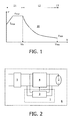
- a power versus voltage graph 10 of a gas discharge lamp is shown.
- the power versus voltage graph 10 defines a first state 11 for supplying a first amount of power.
- the power versus voltage graph 10 defines a second state 12 for supplying a second amount of power.
- the first state 11 ends at a boundary voltage value U b of a voltage signal and the second state 12 starts at the boundary voltage value U b .
- the first amount of power comprises an increasing amount of power during a first part of the first state 11 while supplying a maximum current I max to the gas discharge lamp.
- the first amount of power comprises a maximum amount of power P max during a second part of the first state 11.
- the second amount of power comprises a decreasing amount of power until a steady state voltage value U stst of the voltage signal has been reached.
- the power versus voltage graph 10 defines a third state 13 for supplying a third amount of power.
- the third state 13 starts at the steady state voltage value U stst .
- the third amount of power comprises a stable amount of power.
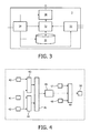
- a system 6 comprising a device 1.
- the system 6 further comprises a gas discharge lamp 2 connected to a supply circuit 4 for supplying an amount of power according to the power versus voltage graph 10 shown in the Fig. 1 .
- the supply circuit 4 supplies for example a current signal to the gas discharge lamp 2, which current signal results in a voltage signal across the gas discharge lamp 2.
- a combination of these current and voltage signals defines an amount of power.
- the supply circuit 4 is for example connected to a rectifier 5 for rectifying a mains voltage. Alternatively, a battery may be used.
- the device 1 comprises a control circuit 3 connected to the gas discharge lamp 2 (in parallel to the supply circuit 4) and for example connected to the rectifier 5 (in parallel to the supply circuit 4).
- a control output of the control circuit 3 is connected to a control input of the supply circuit 4.
- an ignition circuit may be present (not shown).
- the control circuit 3 comprises a calculator 30 for calculating the boundary voltage value U b as a function of a measured voltage value U T of the voltage signal that has been measured after a predefined time-interval from a cold start of the gas discharge lamp 2.
- the calculator 30 may further calculate the boundary voltage value U b as a function of a minimum voltage value U mm of the voltage signal and as a function of a steady state voltage value U stst of the voltage signal.
- An output of the calculator 30 constitutes the control output of the control circuit 3 and an input of the calculator 30 is for example connected to a processor 32.
- the processor 32 is connected to a memory 31 and is for example connected to a voltage determining circuit 33 and a feeding circuit 34.
- the feeding circuit 34 for example feeds the calculator 30, the memory 31, the processor 32 and the voltage determining circuit 33.
- the voltage determining circuit 33 determines the measured voltage value U T of the voltage signal by for example measuring this voltage value after a predefined time-interval from a cold start of the gas discharge lamp 2 in response to an instruction from the processor 32.
- the voltage determining circuit 33 may further determine other voltage values of the voltage signal by for example measuring these voltage values and supplying the measured voltage values to the processor 32 to for example find the minimum voltage value U min of the voltage signal and the steady state voltage value U stst of the voltage signal by for example comparing the measured voltage values with each other.
- the processor 32 may thereto comprise an analog comparator or comparing function, alternatively this analog comparator or comparing function may be located inside the voltage determining circuit 33 etc.
- the voltage determining circuit 33 may comprise an analog to digital converter, and the processor 32 may then comprise a digital comparator or comparing function, alternatively this digital comparator or comparing function may be located inside the voltage determining circuit 33 etc.
- the calculator 30 may form part of the processor 32, or vice versa.
- the memory 31 stores the measured voltage value U T of the voltage signal and the processor 32 updates the measured voltage value U T stored in the memory 31.
- the memory 31 may further store the minimum voltage value U min of the voltage signal and the steady state voltage value U stst of the voltage signal and the processor 32 may further update these voltage values stored in the memory 31.
- one or more stored values may be used to calculate the boundary voltage value U b , and one or more recent values may be used for updating the stored values.
- the units 30-33 may be hardware units and/or software units and may form part of a computer or a microcontroller or analog and/or digital control circuitry etc.
- a power defining algorithm is shown.
- a measured voltage value U is presented.
- a (calculated) boundary voltage value U b is presented.
- a (measured) steady state voltage value U stst is presented.
- blocks 43 and 44 differences are determined, and at a block 45 a division is made such that at the output of the block 45 a normalized voltage value U norm is available:
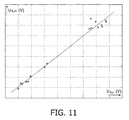
- a boundary voltage U b (V) as a function of the measured voltage U T (V) is shown.
- the measured voltage value U T of the voltage signal is to be measured after a predefined time-interval T from a cold start of the gas discharge lamp 2.
- the Fig. 6 shows a voltage U (V) as a function of a time t (s) for the Fig. 5 .
- U b can be calculated.
- a boundary voltage U b (V) as a function of a minimum voltage U min (V) is shown.
- the Fig. 8 shows a voltage U (V) as a function of a time t (s) for the Fig. 7 .
- a boundary voltage U b (V) as a function of a steady state voltage U stst (V) is shown.
- the Fig. 10 shows a voltage U (V) as a function of a time t (s) for the Fig. 9 .
- U b can be calculated.
- a possible algorithm might be as follows. After the predefined time-interval T, such as for example five, six or seven seconds for a particular kind of gas discharge lamp 2, or such as for example for a more general kind of lamp any time value between two and ten seconds, the voltage value U T of the voltage signal is to be measured. This measured voltage value U T of the voltage signal is to be compared with a previous voltage value U T stored in the memory 31. In response to a first comparison result (non-cold start) the previous voltage value U T stored in the memory 31 is to be replaced by the measured voltage value U T of the voltage signal.
- the previous voltage value U T stored in the memory 31 is to be replaced by a new voltage value U T depending on for example the measured voltage value U T of the voltage signal and one or more, such as for example 20, previously stored voltage values U T .
- the steady state voltage value U stst of the voltage signal is to be measured.
- This steady state voltage value U stst of the voltage signal is to be compared with a previous steady state voltage value U stst stored in the memory 31.
- the previous steady state voltage value U stst stored in the memory 31 is to be replaced by the measured steady state voltage value U stst of the voltage signal.
- the previous steady state voltage value U stst stored in the memory 31 is to be replaced by a new steady state voltage value U stst depending on for example the measured steady state voltage value U stst of the voltage signal and one or more previously stored steady state voltage values U stst .
- a new boundary voltage value U b is to be calculated, and the new boundary voltage value U b and the new steady state voltage value U stst can be used for a next calculation of the amount of power to be provided etc.
- a measurement / determination result can be used for updating the (calculated) other one.
- U T and U stst can be updated. After a non-cold start of the existing particular gas discharge lamp 2, U T can be kept as it is and U stst can be updated. After a cold start of a novel particular gas discharge lamp 2, U T and U stst are to be determined. After a non-cold start of the novel particular gas discharge lamp 2, U T can be kept as it is and U stst can be updated.
- a device 1 for providing an amount of power to a gas discharge lamp 2 comprises a control circuit 3 for controlling a supply circuit 4 for supplying the power according to a power versus voltage graph 10.
- a calculator 30 calculates a boundary voltage value as a function of a measured voltage value of a voltage signal that has been measured after a predefined time-interval from a cold start of the gas discharge lamp 2. A more accurate boundary voltage value results in more accuracy and in less time required to reach a steady state.
- the calculator 30 may be arranged for calculating the boundary voltage value as a function of a minimum voltage value of the voltage signal and of a steady state voltage value of the voltage signal.
- a memory 31 may store voltage values of the voltage signal and a processor 32 may update these voltage values.
Landscapes
- Circuit Arrangements For Discharge Lamps (AREA)
Claims (12)
- Vorrichtung (1), um einer Gasentladungslampe (2) eine Energiemenge zuzuführen, wobei die Vorrichtung (1) einen Steuerkreis (3) umfasst, um eine Versorgungsschaltung (4) so zu steuern, dass sie die Energie gemäß einem Leistungs-/Spannungsdiagramm (10) zuführt, wobei das Leistungs-/Spannungsdiagramm (10) einen ersten Zustand (11) zum Zuführen einer ersten Energiemenge definiert, das Leistungs-/Spannungsdiagramm (10) einen zweiten Zustand (12) zum Zuführen einer zweiten Energiemenge definiert, wobei der erste Zustand (11) bei einem Grenzspannungswert eines Spannungssignals endet und der zweite Zustand (12) bei dem Grenzspannungswert beginnt, dadurch gekennzeichnet, dass der Steuerkreis (3) einen Rechner (30) umfasst, um den Grenzspannungswert als eine Funktion eines Spannungsmesswertes des Spannungssignals, der nach einem zuvor festgelegten Zeitintervall ab einem Kaltstart der Gasentladungslampe (2) gemessen wurde, zu berechnen.
- Vorrichtung (1) nach Anspruch 1, wobei der Rechner (30) so eingerichtet ist, dass er den Grenzspannungswert als eine Funktion eines Mindestspannungswertes des Spannungssignals sowie als eine Funktion eines Stationärspannungswertes des Spannungssignals berechnet.
- Vorrichtung (1) nach Anspruch 2, wobei die Funktion des Spannungsmesswertes des Spannungssignals einen ersten Wichtungsfaktor umfasst, die Funktion des Mindestspannungswertes des Spannungssignals einen zweiten Wichtungsfaktor umfasst und die Funktion des Stationärspannungswertes des Spannungssignals einen dritten Wichtungsfaktor umfasst, wobei eine Summe der Wichtungsfaktoren einem zuvor festgelegten Wert entspricht.
- Vorrichtung (1) nach Anspruch 2, wobei die erste Energiemenge während eines ersten Teils des ersten Zustands (11), in dem der Gasentladungslampe (2) ein Maximalstrom zugeführt wird, eine ansteigende Energiemenge beinhaltet, wobei die erste Energiemenge während eines zweiten Teils des ersten Zustands (11) eine maximale Energiemenge beinhaltet, und wobei die zweite Energiemenge bis zum Erreichen des Stationärspannungswertes des Spannungssignals eine abnehmende Energiemenge beinhaltet.
- Vorrichtung (1) nach Anspruch 2, wobei das Leistungs-/Spannungsdiagramm (10) einen dritten Zustand (13) zum Zuführen einer dritten Energiemenge definiert, wobei der dritte Zustand (13) bei dem Stationärspannungswert des Spannungssignals beginnt, wobei die dritte Energiemenge eine stabile Energiemenge beinhaltet.
- Vorrichtung (1) nach Anspruch 1, wobei der Steuerkreis (3) einen Speicher (31) zur Speicherung des Spannungsmesswertes des Spannungssignals sowie einen Prozessor (32) zur Aktualisierung des in dem Speicher (31) gespeicherten Spannungsmesswertes umfasst.
- Vorrichtung (1) nach Anspruch 2, wobei der Steuerkreis (3) einen Speicher (31) zur Speicherung des Spannungsmesswertes des Spannungssignals und des Mindestspannungswertes des Spannungssignals sowie des Stationärspannungswertes des Spannungssignals umfasst und einen Prozessor (32) zur Aktualisierung der in dem Speicher (31) gespeicherten Spannungsmesswerte aufweist.
- Vorrichtung (1) nach Anspruch 1, wobei die Vorrichtung (1) ein elektronisches Vorschaltgerät für die Gasentladungslampe (2) ist.
- System (6) mit der Vorrichtung (1) nach Anspruch 1 sowie der Versorgungsschaltung (4) und/oder der Gasentladungslampe (2).
- Verfahren, um einer Gasentladungslampe (2) eine Energiemenge zuzuführen, wobei das Verfahren die folgenden Schritte umfasst, wonach eine Zufuhr der Energie gemäß einem Leistungs-/Spannungsdiagramm (10) gesteuert wird, wobei das Leistungs-/Spannungsdiagramm (10) einen ersten Zustand (11) zum Zuführen einer ersten Energiemenge definiert, das Leistungs-/Spannungsdiagramm (10) einen zweiten Zustand (12) zum Zuführen einer zweiten Energiemenge definiert, wobei der erste Zustand (11) bei einem Grenzspannungswert eines Spannungssignals endet und der zweite Zustand (12) bei dem Grenzspannungswert beginnt, dadurch gekennzeichnet, dass der Steuerungsschritt einen Teilschritt des Berechnens des Grenzspannungswertes als eine Funktion eines Spannungsmesswertes des Spannungssignals, der nach einem zuvor festgelegten Zeitintervall ab einem Kaltstart der Gasentladungslampe (2) gemessen wurde, umfasst.
- Computerprogrammprodukt zur Durchführung des Schrittes des Verfahrens nach Anspruch 10.
- Medium zur Speicherung und Aufnahme des Computerprogrammprodukts nach Anspruch 11.
Priority Applications (1)
| Application Number | Priority Date | Filing Date | Title |
|---|---|---|---|
| EP09771414A EP2345311B1 (de) | 2008-11-07 | 2009-11-03 | Energiezufuhr für gasentladungslampe |
Applications Claiming Priority (3)
| Application Number | Priority Date | Filing Date | Title |
|---|---|---|---|
| EP08168612 | 2008-11-07 | ||
| PCT/IB2009/054877 WO2010052641A2 (en) | 2008-11-07 | 2009-11-03 | Providing power to gas discharge lamp |
| EP09771414A EP2345311B1 (de) | 2008-11-07 | 2009-11-03 | Energiezufuhr für gasentladungslampe |
Publications (2)
| Publication Number | Publication Date |
|---|---|
| EP2345311A2 EP2345311A2 (de) | 2011-07-20 |
| EP2345311B1 true EP2345311B1 (de) | 2012-07-18 |
Family
ID=42077765
Family Applications (1)
| Application Number | Title | Priority Date | Filing Date |
|---|---|---|---|
| EP09771414A Active EP2345311B1 (de) | 2008-11-07 | 2009-11-03 | Energiezufuhr für gasentladungslampe |
Country Status (5)
| Country | Link |
|---|---|
| US (1) | US10542612B2 (de) |
| EP (1) | EP2345311B1 (de) |
| JP (1) | JP6017787B2 (de) |
| CN (1) | CN102210195B (de) |
| WO (1) | WO2010052641A2 (de) |
Families Citing this family (22)
| Publication number | Priority date | Publication date | Assignee | Title |
|---|---|---|---|---|
| JP5212527B2 (ja) * | 2010-09-01 | 2013-06-19 | 株式会社デンソー | 放電灯点灯装置 |
| US9561476B2 (en) | 2010-12-15 | 2017-02-07 | Praxair Technology, Inc. | Catalyst containing oxygen transport membrane |
| US8409323B2 (en) | 2011-04-07 | 2013-04-02 | Praxair Technology, Inc. | Control method and apparatus |
| US9486735B2 (en) | 2011-12-15 | 2016-11-08 | Praxair Technology, Inc. | Composite oxygen transport membrane |
| WO2013089895A1 (en) | 2011-12-15 | 2013-06-20 | Praxair Technology, Inc. | Composite oxygen transport membrane |
| WO2014100376A1 (en) | 2012-12-19 | 2014-06-26 | Praxair Technology, Inc. | Method for sealing an oxygen transport membrane assembly |
| US9453644B2 (en) | 2012-12-28 | 2016-09-27 | Praxair Technology, Inc. | Oxygen transport membrane based advanced power cycle with low pressure synthesis gas slip stream |
| US9611144B2 (en) | 2013-04-26 | 2017-04-04 | Praxair Technology, Inc. | Method and system for producing a synthesis gas in an oxygen transport membrane based reforming system that is free of metal dusting corrosion |
| US9212113B2 (en) | 2013-04-26 | 2015-12-15 | Praxair Technology, Inc. | Method and system for producing a synthesis gas using an oxygen transport membrane based reforming system with secondary reforming and auxiliary heat source |
| US9938145B2 (en) | 2013-04-26 | 2018-04-10 | Praxair Technology, Inc. | Method and system for adjusting synthesis gas module in an oxygen transport membrane based reforming system |
| US9296671B2 (en) | 2013-04-26 | 2016-03-29 | Praxair Technology, Inc. | Method and system for producing methanol using an integrated oxygen transport membrane based reforming system |
| WO2015054228A2 (en) | 2013-10-07 | 2015-04-16 | Praxair Technology, Inc. | Ceramic oxygen transport membrane array reactor and reforming method |
| CA2924201A1 (en) | 2013-10-08 | 2015-04-16 | Praxair Technology, Inc. | System and method for temperature control in an oxygen transport membrane based reactor |
| CN105764842B (zh) | 2013-12-02 | 2018-06-05 | 普莱克斯技术有限公司 | 使用具有二段转化的基于氧转运膜的重整系统生产氢气的方法和系统 |
| WO2015123246A2 (en) | 2014-02-12 | 2015-08-20 | Praxair Technology, Inc. | Oxygen transport membrane reactor based method and system for generating electric power |
| WO2015160609A1 (en) | 2014-04-16 | 2015-10-22 | Praxair Technology, Inc. | Method and system for oxygen transport membrane enhanced integrated gasifier combined cycle (igcc) |
| US9789445B2 (en) | 2014-10-07 | 2017-10-17 | Praxair Technology, Inc. | Composite oxygen ion transport membrane |
| US10441922B2 (en) | 2015-06-29 | 2019-10-15 | Praxair Technology, Inc. | Dual function composite oxygen transport membrane |
| US10118823B2 (en) | 2015-12-15 | 2018-11-06 | Praxair Technology, Inc. | Method of thermally-stabilizing an oxygen transport membrane-based reforming system |
| US9938146B2 (en) | 2015-12-28 | 2018-04-10 | Praxair Technology, Inc. | High aspect ratio catalytic reactor and catalyst inserts therefor |
| CN109070014A (zh) | 2016-04-01 | 2018-12-21 | 普莱克斯技术有限公司 | 含催化剂的氧气传送膜 |
| US11136238B2 (en) | 2018-05-21 | 2021-10-05 | Praxair Technology, Inc. | OTM syngas panel with gas heated reformer |
Family Cites Families (19)
| Publication number | Priority date | Publication date | Assignee | Title |
|---|---|---|---|---|
| JP3180353B2 (ja) * | 1991-02-06 | 2001-06-25 | 三菱電機株式会社 | 放電灯点灯装置 |
| JP4050474B2 (ja) * | 2001-02-26 | 2008-02-20 | 株式会社小糸製作所 | 放電灯点灯回路 |
| JP2003151787A (ja) | 2001-08-29 | 2003-05-23 | Harison Toshiba Lighting Corp | 高圧放電ランプ点灯装置および自動車用ヘッドライト装置 |
| US6914395B2 (en) * | 2001-11-27 | 2005-07-05 | Matsushita Electric Works, Ltd. | Electronic ballast for a high-pressure discharge lamp |
| US7091673B2 (en) * | 2002-07-02 | 2006-08-15 | Mitsubishi Denki Kabushiki Kaisha | Discharge lamp lighting device |
| DE10319950A1 (de) * | 2003-05-02 | 2004-11-18 | Patent-Treuhand-Gesellschaft für elektrische Glühlampen mbH | Betriebsgerät und Verfahren zum Betreiben von Gasentladungslampen |
| JP2005026032A (ja) * | 2003-07-01 | 2005-01-27 | Koito Mfg Co Ltd | 放電灯点灯回路 |
| JP2005026071A (ja) * | 2003-07-02 | 2005-01-27 | Koito Mfg Co Ltd | 放電灯点灯回路 |
| EP1740022A4 (de) * | 2004-04-23 | 2012-11-07 | Panasonic Corp | Entladungslampen-betriebseinrichtung, beleuchtungseinrichtung und beleuchtungssystem |
| JP4400872B2 (ja) * | 2004-07-16 | 2010-01-20 | 株式会社小糸製作所 | 放電灯点灯装置 |
| JP2006073310A (ja) | 2004-09-01 | 2006-03-16 | Sumida Corporation | 高圧放電灯点灯装置、および高圧放電灯の点灯制御方法 |
| JP2006164677A (ja) | 2004-12-06 | 2006-06-22 | Harison Toshiba Lighting Corp | 高圧放電灯の点灯装置 |
| ES2694647T3 (es) | 2005-02-02 | 2018-12-26 | Lumileds Holding B.V. | Módulo de fuente de luz y soporte para el mismo |
| DE102006009739A1 (de) * | 2005-03-04 | 2006-09-28 | Stanley Electric Co. Ltd. | Entladungslampenanschaltvorrichtung und Entladungslampenanschaltverfahren |
| JP4572731B2 (ja) | 2005-04-25 | 2010-11-04 | パナソニック電工株式会社 | 放電灯点灯装置および照明器具 |
| JP4794921B2 (ja) * | 2005-06-21 | 2011-10-19 | 三菱電機株式会社 | 放電灯点灯装置 |
| US8390211B2 (en) * | 2005-10-17 | 2013-03-05 | Abl Ip Holding Llc | Constant lumen output control system |
| JP4475433B2 (ja) * | 2007-02-13 | 2010-06-09 | セイコーエプソン株式会社 | 放電灯点灯制御装置及びプロジェクタ |
| JP5010320B2 (ja) | 2007-03-26 | 2012-08-29 | パナソニック株式会社 | 放電灯点灯装置、照明器具及び照明システム |
-
2009
- 2009-11-03 EP EP09771414A patent/EP2345311B1/de active Active
- 2009-11-03 WO PCT/IB2009/054877 patent/WO2010052641A2/en active Application Filing
- 2009-11-03 JP JP2011533920A patent/JP6017787B2/ja active Active
- 2009-11-03 US US13/126,256 patent/US10542612B2/en active Active
- 2009-11-03 CN CN200980144373.3A patent/CN102210195B/zh active Active
Also Published As
| Publication number | Publication date |
|---|---|
| CN102210195B (zh) | 2014-02-12 |
| US10542612B2 (en) | 2020-01-21 |
| JP6017787B2 (ja) | 2016-11-02 |
| EP2345311A2 (de) | 2011-07-20 |
| JP2012508430A (ja) | 2012-04-05 |
| WO2010052641A2 (en) | 2010-05-14 |
| CN102210195A (zh) | 2011-10-05 |
| US20110204822A1 (en) | 2011-08-25 |
| WO2010052641A3 (en) | 2010-12-02 |
Similar Documents
| Publication | Publication Date | Title |
|---|---|---|
| EP2345311B1 (de) | Energiezufuhr für gasentladungslampe | |
| US7002305B2 (en) | Electronic ballast for a discharge lamp | |
| AU2013260671B2 (en) | Method for adjustably controlling light and apparatus thereof | |
| US20100219774A1 (en) | Method for dimming light sources, related device and computer program product | |
| US7675244B2 (en) | System and method for power supply for lamp with improved constant power mode control and improved boost current circuit | |
| JP2008295169A (ja) | バッテリーパック、充電装置、及び電子機器 | |
| JP2010057249A (ja) | 充電装置および充電制御方法 | |
| JPH1145782A (ja) | 調光監視制御システム | |
| JP3326968B2 (ja) | 放電灯点灯装置 | |
| JPH11162524A (ja) | 電池残量検出装置 | |
| JP2005353357A (ja) | 電子安定器 | |
| US8148920B2 (en) | Method of controlling a ballast for a high intensity discharge lamp and related system | |
| TWI486099B (zh) | 供應燈具功率以操作至少一氣體放電燈之方法與電路裝置 | |
| JP4259140B2 (ja) | 照明装置 | |
| JP6763737B2 (ja) | 電子機器、および電子機器の制御方法 | |
| CN113937866B (zh) | 控制设备运行的方法、装置、终端设备及存储介质 | |
| JP4379283B2 (ja) | 充電回路、非常用点灯装置及び照明装置 | |
| CN118102553B (zh) | 一种照度调光控制方法及照明系统、控制装置、存储介质 | |
| JP2020004617A (ja) | 制御装置、制御装置の制御方法、及び、照明装置 | |
| JP2010057248A (ja) | 充電装置および充電制御方法 | |
| JP6160219B2 (ja) | 点灯装置および照明器具 | |
| BE1028690B1 (nl) | Digitale bediening met thermostaatfunctie | |
| JP2842490B2 (ja) | 高圧放電灯点灯装置 | |
| EP3820254A1 (de) | Verbesserte zeitmessgenauigkeit für eine gleichstromversorgung | |
| JP4534678B2 (ja) | 放電灯点灯装置、照明器具及び照明システム |
Legal Events
| Date | Code | Title | Description |
|---|---|---|---|
| PUAI | Public reference made under article 153(3) epc to a published international application that has entered the european phase |
Free format text: ORIGINAL CODE: 0009012 |
|
| 17P | Request for examination filed |
Effective date: 20110607 |
|
| AK | Designated contracting states |
Kind code of ref document: A2 Designated state(s): AT BE BG CH CY CZ DE DK EE ES FI FR GB GR HR HU IE IS IT LI LT LU LV MC MK MT NL NO PL PT RO SE SI SK SM TR |
|
| AX | Request for extension of the european patent |
Extension state: AL BA RS |
|
| GRAP | Despatch of communication of intention to grant a patent |
Free format text: ORIGINAL CODE: EPIDOSNIGR1 |
|
| DAX | Request for extension of the european patent (deleted) | ||
| GRAS | Grant fee paid |
Free format text: ORIGINAL CODE: EPIDOSNIGR3 |
|
| GRAA | (expected) grant |
Free format text: ORIGINAL CODE: 0009210 |
|
| AK | Designated contracting states |
Kind code of ref document: B1 Designated state(s): AT BE BG CH CY CZ DE DK EE ES FI FR GB GR HR HU IE IS IT LI LT LU LV MC MK MT NL NO PL PT RO SE SI SK SM TR |
|
| REG | Reference to a national code |
Ref country code: GB Ref legal event code: FG4D |
|
| REG | Reference to a national code |
Ref country code: CH Ref legal event code: EP |
|
| REG | Reference to a national code |
Ref country code: AT Ref legal event code: REF Ref document number: 567324 Country of ref document: AT Kind code of ref document: T Effective date: 20120815 Ref country code: IE Ref legal event code: FG4D |
|
| REG | Reference to a national code |
Ref country code: DE Ref legal event code: R096 Ref document number: 602009008398 Country of ref document: DE Effective date: 20120906 |
|
| REG | Reference to a national code |
Ref country code: DE Ref legal event code: R084 Ref document number: 602009008398 Country of ref document: DE |
|
| REG | Reference to a national code |
Ref country code: GB Ref legal event code: 746 Effective date: 20120928 |
|
| REG | Reference to a national code |
Ref country code: DE Ref legal event code: R084 Ref document number: 602009008398 Country of ref document: DE Effective date: 20120922 |
|
| REG | Reference to a national code |
Ref country code: NL Ref legal event code: VDEP Effective date: 20120718 |
|
| REG | Reference to a national code |
Ref country code: AT Ref legal event code: MK05 Ref document number: 567324 Country of ref document: AT Kind code of ref document: T Effective date: 20120718 |
|
| REG | Reference to a national code |
Ref country code: LT Ref legal event code: MG4D Effective date: 20120718 |
|
| PG25 | Lapsed in a contracting state [announced via postgrant information from national office to epo] |
Ref country code: HR Free format text: LAPSE BECAUSE OF FAILURE TO SUBMIT A TRANSLATION OF THE DESCRIPTION OR TO PAY THE FEE WITHIN THE PRESCRIBED TIME-LIMIT Effective date: 20120718 Ref country code: BE Free format text: LAPSE BECAUSE OF FAILURE TO SUBMIT A TRANSLATION OF THE DESCRIPTION OR TO PAY THE FEE WITHIN THE PRESCRIBED TIME-LIMIT Effective date: 20120718 Ref country code: FI Free format text: LAPSE BECAUSE OF FAILURE TO SUBMIT A TRANSLATION OF THE DESCRIPTION OR TO PAY THE FEE WITHIN THE PRESCRIBED TIME-LIMIT Effective date: 20120718 Ref country code: AT Free format text: LAPSE BECAUSE OF FAILURE TO SUBMIT A TRANSLATION OF THE DESCRIPTION OR TO PAY THE FEE WITHIN THE PRESCRIBED TIME-LIMIT Effective date: 20120718 Ref country code: NO Free format text: LAPSE BECAUSE OF FAILURE TO SUBMIT A TRANSLATION OF THE DESCRIPTION OR TO PAY THE FEE WITHIN THE PRESCRIBED TIME-LIMIT Effective date: 20121018 Ref country code: IS Free format text: LAPSE BECAUSE OF FAILURE TO SUBMIT A TRANSLATION OF THE DESCRIPTION OR TO PAY THE FEE WITHIN THE PRESCRIBED TIME-LIMIT Effective date: 20121118 Ref country code: LT Free format text: LAPSE BECAUSE OF FAILURE TO SUBMIT A TRANSLATION OF THE DESCRIPTION OR TO PAY THE FEE WITHIN THE PRESCRIBED TIME-LIMIT Effective date: 20120718 Ref country code: CY Free format text: LAPSE BECAUSE OF FAILURE TO SUBMIT A TRANSLATION OF THE DESCRIPTION OR TO PAY THE FEE WITHIN THE PRESCRIBED TIME-LIMIT Effective date: 20120718 |
|
| PG25 | Lapsed in a contracting state [announced via postgrant information from national office to epo] |
Ref country code: GR Free format text: LAPSE BECAUSE OF FAILURE TO SUBMIT A TRANSLATION OF THE DESCRIPTION OR TO PAY THE FEE WITHIN THE PRESCRIBED TIME-LIMIT Effective date: 20121019 Ref country code: LV Free format text: LAPSE BECAUSE OF FAILURE TO SUBMIT A TRANSLATION OF THE DESCRIPTION OR TO PAY THE FEE WITHIN THE PRESCRIBED TIME-LIMIT Effective date: 20120718 Ref country code: PT Free format text: LAPSE BECAUSE OF FAILURE TO SUBMIT A TRANSLATION OF THE DESCRIPTION OR TO PAY THE FEE WITHIN THE PRESCRIBED TIME-LIMIT Effective date: 20121119 Ref country code: PL Free format text: LAPSE BECAUSE OF FAILURE TO SUBMIT A TRANSLATION OF THE DESCRIPTION OR TO PAY THE FEE WITHIN THE PRESCRIBED TIME-LIMIT Effective date: 20120718 Ref country code: SE Free format text: LAPSE BECAUSE OF FAILURE TO SUBMIT A TRANSLATION OF THE DESCRIPTION OR TO PAY THE FEE WITHIN THE PRESCRIBED TIME-LIMIT Effective date: 20120718 Ref country code: SI Free format text: LAPSE BECAUSE OF FAILURE TO SUBMIT A TRANSLATION OF THE DESCRIPTION OR TO PAY THE FEE WITHIN THE PRESCRIBED TIME-LIMIT Effective date: 20120718 |
|
| PG25 | Lapsed in a contracting state [announced via postgrant information from national office to epo] |
Ref country code: NL Free format text: LAPSE BECAUSE OF FAILURE TO SUBMIT A TRANSLATION OF THE DESCRIPTION OR TO PAY THE FEE WITHIN THE PRESCRIBED TIME-LIMIT Effective date: 20120718 |
|
| PG25 | Lapsed in a contracting state [announced via postgrant information from national office to epo] |
Ref country code: EE Free format text: LAPSE BECAUSE OF FAILURE TO SUBMIT A TRANSLATION OF THE DESCRIPTION OR TO PAY THE FEE WITHIN THE PRESCRIBED TIME-LIMIT Effective date: 20120718 Ref country code: DK Free format text: LAPSE BECAUSE OF FAILURE TO SUBMIT A TRANSLATION OF THE DESCRIPTION OR TO PAY THE FEE WITHIN THE PRESCRIBED TIME-LIMIT Effective date: 20120718 Ref country code: CZ Free format text: LAPSE BECAUSE OF FAILURE TO SUBMIT A TRANSLATION OF THE DESCRIPTION OR TO PAY THE FEE WITHIN THE PRESCRIBED TIME-LIMIT Effective date: 20120718 Ref country code: RO Free format text: LAPSE BECAUSE OF FAILURE TO SUBMIT A TRANSLATION OF THE DESCRIPTION OR TO PAY THE FEE WITHIN THE PRESCRIBED TIME-LIMIT Effective date: 20120718 |
|
| PLBE | No opposition filed within time limit |
Free format text: ORIGINAL CODE: 0009261 |
|
| STAA | Information on the status of an ep patent application or granted ep patent |
Free format text: STATUS: NO OPPOSITION FILED WITHIN TIME LIMIT |
|
| PG25 | Lapsed in a contracting state [announced via postgrant information from national office to epo] |
Ref country code: SK Free format text: LAPSE BECAUSE OF FAILURE TO SUBMIT A TRANSLATION OF THE DESCRIPTION OR TO PAY THE FEE WITHIN THE PRESCRIBED TIME-LIMIT Effective date: 20120718 Ref country code: IT Free format text: LAPSE BECAUSE OF FAILURE TO SUBMIT A TRANSLATION OF THE DESCRIPTION OR TO PAY THE FEE WITHIN THE PRESCRIBED TIME-LIMIT Effective date: 20120718 |
|
| 26N | No opposition filed |
Effective date: 20130419 |
|
| PG25 | Lapsed in a contracting state [announced via postgrant information from national office to epo] |
Ref country code: BG Free format text: LAPSE BECAUSE OF FAILURE TO SUBMIT A TRANSLATION OF THE DESCRIPTION OR TO PAY THE FEE WITHIN THE PRESCRIBED TIME-LIMIT Effective date: 20121018 |
|
| REG | Reference to a national code |
Ref country code: IE Ref legal event code: MM4A Ref country code: DE Ref legal event code: R097 Ref document number: 602009008398 Country of ref document: DE Effective date: 20130419 |
|
| PG25 | Lapsed in a contracting state [announced via postgrant information from national office to epo] |
Ref country code: IE Free format text: LAPSE BECAUSE OF NON-PAYMENT OF DUE FEES Effective date: 20121103 Ref country code: ES Free format text: LAPSE BECAUSE OF FAILURE TO SUBMIT A TRANSLATION OF THE DESCRIPTION OR TO PAY THE FEE WITHIN THE PRESCRIBED TIME-LIMIT Effective date: 20121029 |
|
| PG25 | Lapsed in a contracting state [announced via postgrant information from national office to epo] |
Ref country code: MT Free format text: LAPSE BECAUSE OF FAILURE TO SUBMIT A TRANSLATION OF THE DESCRIPTION OR TO PAY THE FEE WITHIN THE PRESCRIBED TIME-LIMIT Effective date: 20120718 |
|
| PG25 | Lapsed in a contracting state [announced via postgrant information from national office to epo] |
Ref country code: MC Free format text: LAPSE BECAUSE OF NON-PAYMENT OF DUE FEES Effective date: 20121130 Ref country code: TR Free format text: LAPSE BECAUSE OF FAILURE TO SUBMIT A TRANSLATION OF THE DESCRIPTION OR TO PAY THE FEE WITHIN THE PRESCRIBED TIME-LIMIT Effective date: 20120718 |
|
| REG | Reference to a national code |
Ref country code: DE Ref legal event code: R081 Ref document number: 602009008398 Country of ref document: DE Owner name: PHILIPS GMBH, DE Free format text: FORMER OWNER: PHILIPS INTELLECTUAL PROPERTY & STANDARDS GMBH, 20099 HAMBURG, DE Effective date: 20140327 Ref country code: DE Ref legal event code: R081 Ref document number: 602009008398 Country of ref document: DE Owner name: PHILIPS DEUTSCHLAND GMBH, DE Free format text: FORMER OWNER: PHILIPS INTELLECTUAL PROPERTY & STANDARDS GMBH, 20099 HAMBURG, DE Effective date: 20140327 |
|
| PG25 | Lapsed in a contracting state [announced via postgrant information from national office to epo] |
Ref country code: LU Free format text: LAPSE BECAUSE OF NON-PAYMENT OF DUE FEES Effective date: 20121103 Ref country code: SM Free format text: LAPSE BECAUSE OF FAILURE TO SUBMIT A TRANSLATION OF THE DESCRIPTION OR TO PAY THE FEE WITHIN THE PRESCRIBED TIME-LIMIT Effective date: 20120718 |
|
| REG | Reference to a national code |
Ref country code: CH Ref legal event code: PL |
|
| PG25 | Lapsed in a contracting state [announced via postgrant information from national office to epo] |
Ref country code: CH Free format text: LAPSE BECAUSE OF NON-PAYMENT OF DUE FEES Effective date: 20131130 Ref country code: LI Free format text: LAPSE BECAUSE OF NON-PAYMENT OF DUE FEES Effective date: 20131130 Ref country code: HU Free format text: LAPSE BECAUSE OF FAILURE TO SUBMIT A TRANSLATION OF THE DESCRIPTION OR TO PAY THE FEE WITHIN THE PRESCRIBED TIME-LIMIT Effective date: 20091103 |
|
| REG | Reference to a national code |
Ref country code: FR Ref legal event code: CD Owner name: PHILIPS INTELLECTUAL PROPERTY & STANDARDS GMBH, DE Effective date: 20141126 Ref country code: FR Ref legal event code: CA Effective date: 20141126 Ref country code: FR Ref legal event code: CD Owner name: KONINKLIJKE PHILIPS ELECTRONICS N.V., NL Effective date: 20141126 |
|
| REG | Reference to a national code |
Ref country code: DE Ref legal event code: R082 Ref document number: 602009008398 Country of ref document: DE Representative=s name: MEISSNER, BOLTE & PARTNER GBR, DE Ref country code: DE Ref legal event code: R081 Ref document number: 602009008398 Country of ref document: DE Owner name: PHILIPS GMBH, DE Free format text: FORMER OWNER: PHILIPS DEUTSCHLAND GMBH, 20099 HAMBURG, DE Ref country code: DE Ref legal event code: R082 Ref document number: 602009008398 Country of ref document: DE Representative=s name: MEISSNER BOLTE PATENTANWAELTE RECHTSANWAELTE P, DE |
|
| PG25 | Lapsed in a contracting state [announced via postgrant information from national office to epo] |
Ref country code: MK Free format text: LAPSE BECAUSE OF FAILURE TO SUBMIT A TRANSLATION OF THE DESCRIPTION OR TO PAY THE FEE WITHIN THE PRESCRIBED TIME-LIMIT Effective date: 20120718 |
|
| REG | Reference to a national code |
Ref country code: FR Ref legal event code: PLFP Year of fee payment: 7 |
|
| REG | Reference to a national code |
Ref country code: FR Ref legal event code: PLFP Year of fee payment: 8 |
|
| REG | Reference to a national code |
Ref country code: FR Ref legal event code: PLFP Year of fee payment: 9 |
|
| REG | Reference to a national code |
Ref country code: GB Ref legal event code: 732E Free format text: REGISTERED BETWEEN 20180920 AND 20180926 |
|
| REG | Reference to a national code |
Ref country code: DE Ref legal event code: R082 Ref document number: 602009008398 Country of ref document: DE Ref country code: DE Ref legal event code: R081 Ref document number: 602009008398 Country of ref document: DE Owner name: LUMILEDS HOLDING B.V., NL Free format text: FORMER OWNER: PHILIPS GMBH, 20099 HAMBURG, DE |
|
| PGFP | Annual fee paid to national office [announced via postgrant information from national office to epo] |
Ref country code: GB Payment date: 20231121 Year of fee payment: 15 |
|
| PGFP | Annual fee paid to national office [announced via postgrant information from national office to epo] |
Ref country code: FR Payment date: 20231123 Year of fee payment: 15 Ref country code: DE Payment date: 20231127 Year of fee payment: 15 |