EP2335867A1 - Appareil d'aspiration et installation d'aspiration - Google Patents
Appareil d'aspiration et installation d'aspiration Download PDFInfo
- Publication number
- EP2335867A1 EP2335867A1 EP10194803A EP10194803A EP2335867A1 EP 2335867 A1 EP2335867 A1 EP 2335867A1 EP 10194803 A EP10194803 A EP 10194803A EP 10194803 A EP10194803 A EP 10194803A EP 2335867 A1 EP2335867 A1 EP 2335867A1
- Authority
- EP
- European Patent Office
- Prior art keywords
- suction
- obturator
- dirt collecting
- collecting container
- suction device
- Prior art date
- Legal status (The legal status is an assumption and is not a legal conclusion. Google has not performed a legal analysis and makes no representation as to the accuracy of the status listed.)
- Granted
Links
Images


Classifications
-
- B—PERFORMING OPERATIONS; TRANSPORTING
- B23—MACHINE TOOLS; METAL-WORKING NOT OTHERWISE PROVIDED FOR
- B23Q—DETAILS, COMPONENTS, OR ACCESSORIES FOR MACHINE TOOLS, e.g. ARRANGEMENTS FOR COPYING OR CONTROLLING; MACHINE TOOLS IN GENERAL CHARACTERISED BY THE CONSTRUCTION OF PARTICULAR DETAILS OR COMPONENTS; COMBINATIONS OR ASSOCIATIONS OF METAL-WORKING MACHINES, NOT DIRECTED TO A PARTICULAR RESULT
- B23Q11/00—Accessories fitted to machine tools for keeping tools or parts of the machine in good working condition or for cooling work; Safety devices specially combined with or arranged in, or specially adapted for use in connection with, machine tools
- B23Q11/0042—Devices for removing chips
- B23Q11/0046—Devices for removing chips by sucking
-
- B—PERFORMING OPERATIONS; TRANSPORTING
- B08—CLEANING
- B08B—CLEANING IN GENERAL; PREVENTION OF FOULING IN GENERAL
- B08B15/00—Preventing escape of dirt or fumes from the area where they are produced; Collecting or removing dirt or fumes from that area
- B08B15/002—Preventing escape of dirt or fumes from the area where they are produced; Collecting or removing dirt or fumes from that area using a central suction system, e.g. for collecting exhaust gases in workshops
-
- B—PERFORMING OPERATIONS; TRANSPORTING
- B23—MACHINE TOOLS; METAL-WORKING NOT OTHERWISE PROVIDED FOR
- B23Q—DETAILS, COMPONENTS, OR ACCESSORIES FOR MACHINE TOOLS, e.g. ARRANGEMENTS FOR COPYING OR CONTROLLING; MACHINE TOOLS IN GENERAL CHARACTERISED BY THE CONSTRUCTION OF PARTICULAR DETAILS OR COMPONENTS; COMBINATIONS OR ASSOCIATIONS OF METAL-WORKING MACHINES, NOT DIRECTED TO A PARTICULAR RESULT
- B23Q11/00—Accessories fitted to machine tools for keeping tools or parts of the machine in good working condition or for cooling work; Safety devices specially combined with or arranged in, or specially adapted for use in connection with, machine tools
- B23Q11/0042—Devices for removing chips
- B23Q11/0057—Devices for removing chips outside the working area
-
- B—PERFORMING OPERATIONS; TRANSPORTING
- B27—WORKING OR PRESERVING WOOD OR SIMILAR MATERIAL; NAILING OR STAPLING MACHINES IN GENERAL
- B27G—ACCESSORY MACHINES OR APPARATUS FOR WORKING WOOD OR SIMILAR MATERIALS; TOOLS FOR WORKING WOOD OR SIMILAR MATERIALS; SAFETY DEVICES FOR WOOD WORKING MACHINES OR TOOLS
- B27G3/00—Arrangements for removing bark-zones, chips, waste, or dust, specially designed for use in connection with wood-working machine or in wood-working plants
Definitions
- the invention relates to a suction device for sucking off a processing member of a machine tool.
- the invention relates to a suction for at least one machine tool.
- Object of the present invention is to provide a suction device and a suction, with the or the improved suction of suction material to a processing member of a machine tool with lower demands on the performance and energy consumption of the extraction system is made possible.
- an inventive suction device comprising a first dirt collecting container with a suction inlet for accumulating on the processing member suction and a first passage for suction material, and a suction unit to pressurize the first dirt collecting container with a negative pressure, a first obturator of a Blocking state, in which a passage of suction material is prevented by the first passage opening, in a passage state in which suction material can pass through the first passage opening, and vice versa, a second dirt collecting container for receiving the first passage opening passing through the suction with a suction outlet, can be connected to the suction line of a suction and over which the second dirt collecting container can be acted upon with negative pressure, and with a second passage for suction and a second obturator, which from a blocking state, in a passage of suction material is prevented by the second passage opening, in a passage state in the suction material can pass through the second passage opening, and vice versa can be transferred.
- the suction device according to the invention is used to support the suction during the suction of accumulating on the processing device suction.
- the suction device can be placed in the immediate vicinity of the machine tool. This makes it possible, by using a connectable to the suction inlet of the first dirt collection container relatively short suction line with a small diameter, for example, 10 cm, to effectively capture suction material on the processing unit and sucked into the first dirt collecting. This is acted upon by the suction unit with negative pressure. If the first obturator adopts the blocking state in which a passage of suction material through the first passage opening is prevented, suction material can be accumulated in the first dirt collecting container.
- the suction material can pass through the first passage opening into the second dirt collecting container and be accumulated therein when the second obturator assumes the blocking state. If the second obturator is transferred to the on-state, due to the negative pressure generated by the central suction unit, the accumulated in the second dirt collecting suction material can pass through the second passage opening and be sucked by the suction.
- the second dirt collector thus effectively serves as a lock, can be passed over the suction material from the first dirt collector to the suction of the suction.
- the transfer of suction material takes place at the suction outlet of the suction device. This makes it possible to make the suction shorter than in a known extraction system. As a result, the amount of air to be moved from the central suction unit of the exhaust system is reduced.
- the central suction unit can thus be dimensioned smaller than in a conventional extraction system, and the requirements for the performance and the energy consumption of the extraction system are reduced.
- the first dirt collecting container can be acted upon continuously by means of the suction unit with negative pressure in order to permanently detect suction material on the processing member.
- the displacement of a machine tool can be made simpler than in the known extraction systems.
- the machine tool can be repositioned together with the suction device which can be placed in its immediate vicinity.
- the relatively small length of the suction line from the processing member to the suction inlet can be maintained, so that the detection rate of suction material on the processing device is still high.
- the dirt collecting container may have a common wall in which the passage opening is formed.
- the second passage opening is arranged at the suction outlet or formed by this. This also allows a simple structural design of the suction device.
- the second obturator can be arranged structurally simple at Saugauslass.
- the second passage opening is arranged at a distance from the suction outlet and that a first space region of the second dirt collection container opens into a second space region of the second dirt collection container via the second passage opening, wherein suction material enters via the first passage opening into the first space region and over can exit the Saugauslass from the second room area.
- Suction material passing through the first passage opening can be collected in the first space region of the second dirt collection container when the second shut-off element assumes the blocking state. After transferring the second obturator in the on-state, the collected suction material can be sucked from the suction through the suction outlet and the second passage opening therethrough.
- the second dirt collecting container comprises an inlet for external air and if the suction device has a third obturator, which can be converted from a blocking state in which the inlet is closed, in an open state in which the inlet is open, and vice versa , External air can flow into the second dirt collector through the inlet. Meanwhile, when the second obturator enters the on-state, an airflow may be formed through the second debris collection container. This facilitates the suction of suction material from the second dirt collecting.
- the second dirt collecting container comprises an inlet for external air, which is closed by means of the blocking state engaging second obturator and is open when the second obturator assumes the on state.
- This allows a simpler structural design of the suction device.
- the second obturator can then be prevented or made possible both a passage of suction material through the second passage opening as well as an influx of foreign air can be prevented or made possible.
- external air of atmospheric pressure can enter the second dirt collecting container through the inlet. It is also possible that the second dirt collecting container is acted upon by the inlet with external air with overpressure, ie with a pressure above the atmospheric pressure.
- At least one obturator has an actuating device for transferring the obturator from the blocking state into the on-state and / or vice versa.
- At least one actuating device is designed as a pneumatic drive. This has proven in practice to be advantageous for reliable operation of the respective obturator.
- all actuators may be designed as pneumatic actuators.
- At least one actuating device is designed as a mechanical, hydraulic or electric drive.
- At least one actuating device can be actuated manually by a user.
- At least one actuating device can be controlled by a control device. This provides a simple way to automate the operation of the suction device and thereby make it as flexible as possible.
- the first obturator and the second obturator alternately take each other the blocking state and the on state by using control signals that are provided by a first actuating device of the first obturator and a second actuator of the second obturator by the control device.
- a first actuating device of the first obturator and a second actuator of the second obturator by the control device As a result, it can be ensured in a simple manner that suction material is reliably passed through the second dirt collecting container for transfer to the extraction system. Suction material accumulated in the first dirt collecting container can enter the second dirt collecting container when the first obturator of the control device to the effect is driven, that it assumes the on-state.
- the second obturator can be controlled so that it assumes the on-state, and the first obturator can be controlled so that it assumes the blocking state again.
- suction material can continue to accumulate, and the suction material in the second dirt collecting container can be transferred to the extraction system.
- first obturator and the second obturator do not simultaneously assume the passage state in each case using control signals which can be provided by the control device to the first actuation device of the first obturator and the second actuation device of the second obturator.
- control signals which can be provided by the control device to the first actuation device of the first obturator and the second actuation device of the second obturator.
- the first obturator and the second obturator not simultaneously assume the on-state, a mutual interference of the suction units of the suction device and the suction system can be largely avoided.
- a reverse flow direction in the suction device undesirable pressure gradient between the pressure in the second dirt collecting container and the pressure in the first dirt collecting container can be largely prevented.
- the second obturator and the third obturator at the same time each take the passage state using control signals that the second actuator of the second obturator and a third actuator of the third obturator are provided by the controller.
- the controller controls the second actuator of the second obturator and a third actuator of the third obturator.
- the first obturator and the third obturator do not simultaneously assume the on state by the use of control signals, the first actuator of the first obturator and the third actuator of the third obturator by the controller are available. It can thereby be avoided that foreign air flowing into the second dirt collecting container is sucked into the first dirt collecting container through the first through opening by means of the suction aggregate, thus impairing the suction of suction material by the processing member.
- At least one obturator is time-controlled from the blocking state into the on-state and / or conversely transferable using a control signal, which is the actuator of the obturator prepared by the control device.
- a control signal which is the actuator of the obturator prepared by the control device.
- At least one obturator in dependence on the amount of suction material in a dirt collecting container from the blocking state in the on-state and / or vice versa can be converted using a control signal that the actuator of the obturator by the controller is provided.
- the operation of the suction device can be adapted to the amount of accumulated suction material.
- the obturator can be actuated such that the amount of suction material in a dirt collecting container does not exceed a maximum amount.
- the suction device may comprise a sensor device.
- the suction device comprises the control device for controlling at least one actuating device.
- the suction device is assigned a control device for controlling at least one actuating device, which does not comprise the suction device itself.
- a central control device of a suction device comprising the suction device which can even be used to control the actuators of several suction devices used.
- the suction device itself comprises a control device and this in turn can also be controlled by a central control device of the suction system.
- At least one obturator is designed as a closing device and comprises a closing element, with which an opening can be closed.
- the closing element assumes a closed position in the blocking state of the obturator and closes the opening.
- the closing element In the on state of the obturator, the closing element assumes a release position and releases the opening.
- the closing element is designed as a flap or as a slide. This allows a simple structural design of the closing element and thus of the obturator.
- the first obturator is designed as a closing device with a closing element in the form of a flap
- the second and the third obturator are closing devices with closing elements in the form of sliders.
- a shut-off device in the form of a closing device can be provided that the closing element is designed as a plug or lid to close the opening. It is also possible that the closing element is designed as a loop, which can enclose a flexible wall of a dirt collecting container and constrict such that a passage of suction material is prevented by the dirt collecting container.
- the area encompassed by the noose of the Dirt collection container defines a sort of passage opening, which is selectively releasable and closable by means of the closing element.
- first obturator and / or the second obturator is designed as a conveying device and comprises a conveying element with which the suction material can be conveyed through the first passage opening or the second passage opening.
- the conveyor can stand still, so that the obturator assumes the blocking state and a delivery of suction material through the passage opening is not possible therethrough.
- suction material can be conveyed through the passage opening, which defines a passage state of the obturator.
- the conveyor is operated continuously during operation of the suction device, so that continuously suction material can be conveyed through the passage opening.
- the corresponding obturator for example, with the commissioning of the suction device from the blocking state in the on state and with the shutdown of the suction device from the on state to the blocking state to be transferred.
- the conveying element is designed as a rotary feeder or as a screw conveyor. This allows a simple structural design of the conveying element and thus the obturator.
- the first obturator is designed as a conveyor with a conveying element in the form of a rotary valve, and if the second and the third obturator closing devices with closing elements in the form of sliders.
- the suction material can enter the second dirt collecting container under the influence of gravity from the first dirt collecting container.
- the first passage opening is expediently at an underside of the first Dirt collecting container and formed for example in a bottom wall of the first dirt collecting container.
- the second dirt collecting container is arranged below the first dirt collecting container.
- the suction device has a first device unit and a detachably connectable with this second device unit, wherein the first unit unit comprises at least the suction unit and a suction inlet having portion of the first dirt collection container and wherein the second unit unit at least the second dirt collecting container and the second Has shut-off.
- the first device unit can for example be placed on a third unit unit, which forms a conventional dirt collecting container for suction material. Suction material sucked by the suction unit can be deposited in the dirt collecting container of the suction device formed in this way.
- the suction device proves to be flexible, because in addition to the use of the machine tool, it can be used as a conventional vacuum cleaner.
- the third unit unit conveniently comprises rollers arranged on the underside, so that the suction device formed thereby can be moved on an installation surface.
- the second appliance unit additionally comprises the first obturator and optionally a wall of the first debris collecting vessel enclosing the first passage opening.
- the essential, the "lock" for suction of suction device of the invention constituting components are thus summarized in the second unit.
- the invention also relates to an exhaust system for at least one machine tool.
- an extraction system which comprises at least one suction device of the type described above, and a central suction unit, a central dirt collecting container which can be acted upon by the latter with negative pressure and which has a suction opening, and at least one suction line. which is connected to the suction opening and to the suction outlet of the at least one suction device.
- the extraction system according to the invention then has the advantages already described in connection with the explanation of the suction device according to the invention.
- the achievable with the advantageous embodiments of the suction device advantages can be achieved with the extraction system.
- the extraction system may comprise a central control device for actuating one or more actuating devices of one or more shut-off devices of the at least one suction device.
- the respective second actuating devices of the second shut-off devices can be controlled by the central control device in such a way that the second shut-off devices of two suction devices do not simultaneously assume the on-state. This makes it possible that only suction of a suction device is sucked from the suction at a certain time. This suction material can then be sucked particularly effective from the suction system.
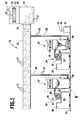
- FIG. 1 A preferred embodiment of an extraction system according to the invention is in FIG. 1 shown schematically and overall occupied by the reference numeral 10.
- the extraction system 10 comprises a housing 11, which receives a central suction unit 12 which is rotationally driven by means of a drive 13.
- a negative pressure can be generated in a central dirt collecting container 14 formed by the housing 11 so that suction material 17 can be sucked in via a suction line 15 connected to a suction opening 15 of the dirt collecting container 14 and deposited in the central dirt collecting container 14.
- the central suction unit 12 is preceded by a filter 18, which can be traversed by suction. Through an outlet 19, the suction air can leave the housing 11.
- the extraction system 10 is used for the extraction of suction material 17 arising from machine tools, of which in the present case two machine tools 20 are shown standing on a floor 21.
- a workpiece 22 can be machined by using a processing member 23.
- the machine tools 20 may be e.g. to deal with separating machine tools, especially woodworking machines.
- the workpiece 22 is, for example, a piece of wood and the processing member 23 is a woodworking device, for example a sawing unit.
- it is in the processing of the workpiece 22 accumulating suction 17 to wood chips or wood dust.
- the suction unit 10 comprises for sucking off the respective suction material 17 accumulating on a processing member 23, in each case a suction head 24 having a hood 25 which overlaps the processing member 23 and the workpiece 22.
- a short suction line 26 connects to the hood 25.
- the suction line 26 is connected with its end facing away from the hood 25 on the input side to a first preferred embodiment of a suction device 27 according to the invention and positioned directly next to the machine tool 20, namely at its suction inlet 28.
- the suction system 10 comprises two identically designed suction devices 27.
- a suction line 29 is connected to the suction outlet 30, which is connected with its suction outlet 30 remote from the end to the suction line 16. In this way, suction material 17 accumulating on the processing device 23 can be sucked through the suction line 26, the suction device 27, the suction line 29 and the suction line 16 and deposited in the central dirt collecting container 14.
- the extraction system 10 comprises a schematically illustrated control device 31, whose operation will be explained below.
- the suction device 27 comprises a housing 32, which receives a suction unit 33 which is rotationally driven by a drive 34. Below the suction unit 33, a filter 35 is held for sucked by the suction unit 33 suction air, and the suction air can leave the housing 32 via an outlet 36.
- the housing 32 On its underside, the housing 32 carries a plurality of rollers 37, so that the suction device 27 can be moved on the floor 21 in a user-friendly manner and can be positioned relative to the machine tool 20 as required.
- the housing 32 forms a two-part container 38, namely with a first dirt collecting container 39 and a second dirt collecting container 40 arranged below it.
- the dirt collecting containers 39 and 40 share a common wall 41, which forms a funnel-shaped bottom wall of the first dirt collecting container 39 and in which a first passage opening 42 for suction material 17 is formed.
- the first dirt collecting container 39 has the suction inlet 28, and the second dirt collecting container 41 has the suction outlet 30.
- the suction outlet 30 forms a second passage opening 43 for suction material 17.
- the second dirt collecting container 40 has a forced air inlet 44 with an inflow opening 45 for ambient air.
- a first obturator 46 is arranged, which is designed in the form of a closing device with a closing element in the form of a flap 47.
- the first passage opening 42 can optionally be closed and released, this defines a closed position or a release position of the flap 47. If the flap 47 assumes its closed position, no suction material 17 can pass through the first passage opening 42. This is referred to as the blocking state of the obturator 46. If, on the other hand, the flap 47 assumes its release position, the suction material 17 can pass from the first dirt collecting container 39 into the second dirt collecting container 40, passing through the first through opening 42. This defines an on-state of the first obturator 46. In FIGS Figures 2 . 4 and 5 the flap 47 assumes its closed position, and in FIG. 3 the flap 47 takes its release position.
- the first obturator 46 comprises an actuator in the form of a particular pneumatic actuator 48 for the flap 47.
- pneumatic actuator 48 could also be a mechanical, an electrical, a hydraulic or other kind of drive used.
- a second obturator 49 is arranged, which is likewise designed in the form of a closing device with a closing element in the form of a slide 50.
- the second passage opening 43 is selectively releasable and closable. If the slide 50 assumes its closed position, no suction material 17 can pass through the second passage 43 ( FIGS. 2 to 4 ). This defines a blocking state of the obturator 49. On the other hand, if the slider 50 assumes its release position, suction material 17 can pass through the second through-opening 43 to step ( FIG. 5 ). This defines an on-state of the obturator 49.
- the obturator 49 comprises a likewise designed as a particular pneumatic drive drive 51st
- a third obturator 52 is arranged on the outside air inlet 44, which is designed in the form of a closing device with a closing element in the form of a slide 53.
- the inflow opening 45 can be closed ( FIGS. 2 to 4 ), this defines a closed position of the slide 53 and a blocking state of the third obturator 52. If the inflow opening 45 is released ( FIG. 5 ), foreign air can flow through the inflow opening 45 into the second dirt collecting container 40. This defines a release position of the slider 53 and an on-state of the third obturator 52.
- the third obturator 52 comprises a likewise designed as a particular pneumatic drive drive 54th
- the drives 48, 51 and 54 are connected via control lines 55, 56 and 57 with a control device 58 of the suction device 27 in operative connection.
- the control lines 55 to 57 are for reasons of clarity only in FIG. 2 and there only slightly.
- the control device 58 can be actuated by the control device 31 of the extraction system 10 via a control line 59 that is shown in the form of a block.
- the drives 48, 51 and 54 can be controlled in the manner described below, so that suction material 17 from the processing member 23 by means of the suction device 27 and the suction system 10 can be sucked in total.
- the suction unit 33 of the suction device 27 is preferably continuously in operation to the first dirt collecting 39 continuously with negative pressure to act on. Since the suction device 27 is arranged directly next to the machine tool 20, suction material 17 accumulated at the processing member 23 via the suction line 26 can be effectively detected with high flow velocity and sucked into the first dirt collecting container 39. At a first time ( FIG. 2 ) take the flap 47 and the slide 50 and 53 each a closed position.
- the control device 58 to drive the drive 48 to move the flap 47 in the release position.
- suction material 17 can fall from the first dirt collecting container 39 into the second dirt collecting container 40 through the first through opening 42 under the influence of gravity.
- the flap 47 is configured only impervious to suction, but not pressure-tight, there is a total of the same pressure when opening the flap 47 in the container 38, which facilitates the opening of the flap 47.
- control device 58 can drive the drive 48 to transfer the flap 47 back into the closed position ( FIG. 4 ).
- control device 58 can drive the drives 51 and 54 such that the slides 50 and 53 are each transferred to their release position ( FIG. 5 ).
- the dirt collecting container 40 is acted upon by the inflow opening 45 incoming external air. This results in the dirt collecting container 40, an air flow, so that the suction material 17 can be effectively sucked through the central suction unit 12.
- the first passage opening 42 is closed with the flap 47. This ensures that no suction material 17 is sucked from the second dirt collecting container 40 back into the first dirt collecting container 39 by means of the suction unit 33.
- the drives 51 and 54 can be controlled again by the control device 58 in such a way that the slides 50 and 53 assume their closed positions ( FIG. 2 ), and the cycle described above may begin again.
- the times at which by means of the control device 58, the drives 48, 51 and 54 are actuated to actuate the flap 47 and the slide 50 and 53, for example, can be preset and / or adjustable. An adjustment of these times as well as the time period during which the flap 47 and the sliders 50 and 53 are opened, can be made for example by a service staff for the suction device 27.
- the drives 48, 51 and 54 are driven depending on demand, depending on the amount of suction material 17 in the first dirt collecting 39 and / or in the second dirt collecting 40.
- the suction device 27 a have corresponding sensor device to detect the amount of suction material 17.
- control device 58 is actuated via the control line 59 by the control device 31 of the suction system 10.
- the control device 31 can the control device 58 opening and closing time and duration of the closed positions and the release orders the flap 47 and the slide 50 and 53 pretend.
- the extraction system 10 comprises more than just a suction device 27, it is possible, in particular, for the suction devices 27 to be sucked off one after the other by means of the central suction unit 12, ie the respective slides 50 of the suction devices 27 are actuated in a time-shifted manner so that the central suction unit 12 only has suction material 17 from each one of the second dirt collecting container 40 sucks ( FIG. 1 ).
- suction material 17 can be effectively detected on the machine tool 20 and transferred to the further components of the suction system 10 via the second dirt collecting container 40 forming a lock.
- This makes it possible to operate the extraction system 10 with a smaller power and with a smaller energy requirement than is the case with the suction systems known from the prior art.
- the performance of the central suction unit 12 can be reduced and the length and the diameter of the suction line 16 and the suction line 29 can be reduced compared to conventional extraction systems.
- suction devices can be used in the suction system 10 instead of the suction device 27.
- FIG. 6 A second preferred embodiment of a suction device according to the invention is in FIG. 6 shown schematically and there occupied by the reference numeral 60.
- the first dirt collecting container 39 has no wall 41 forming the passage opening 42, but the first passage opening 42 is formed over the entire cross-sectional area of the container 38.
- the second passage opening 43 is likewise formed over the entire cross-sectional area of the container 38.
- the second dirt collecting container 40 are divided into a first space area 61 below the first dirt collecting container 39 and a second space area 62 below the first space area 61, which open into one another via the second passage opening 43.
- the first obturator 46 comprises as a closing element a relative to the container 38 horizontally displaceable slide 63 for closing the first passage opening 42.
- the second obturator 49 comprises a relative to the container 38 horizontally displaceable slide 64 for closing the second passage opening 43.
- Saugauslass 30th even no obturator is arranged.
- the forced air inlet 44 and the third shut-off device 52 are arranged on the container 38 such that the inflow opening 45 is arranged in the region of the first space region 61.
- the suction material 17 can be sucked out of the first space region 61 through the second space region 62 by means of the central suction unit 12 ,
- FIG. 6 shows the suction device in one of FIG. 3 corresponding representation in which the slide 63 occupies a release position and the first passage opening 42 is partially released.
- FIG. 7 A third preferred embodiment of a suction device according to the invention is in FIG. 7 shown schematically and there occupied by the reference numeral 65.
- the container 38 with a flexible tubular structure, hereinafter referred to as tube 66 lined.
- the hose 66 is embraced below the suction inlet 28 by a closing element of the first obturator 46 in the form of a loop 67, for example of wire.
- the hose 66 surrounded by a closing element of the second obturator 49 in the form of another, similar loop 68 between the loop 67 and the suction outlet 30. He forms each section a wall of the dirt collection 39 and 40th
- the cross-section of the hose 66 enclosed by the loops 67 and 68 defines the first passage opening 42 and the second passage opening 43, respectively. Accordingly, the second dirt collecting enclosure 40 is subdivided into a first space area 69 between the loops 67 and 68 and into a second space area 70 below Sling 68.
- the tube 66 can be contracted so far that the first passage opening 42 and the second passage opening 43 disappear completely, i. are closed.
- the loop 67 and the loop 68 can be loosened so that the flexible tube 66 expands and the first passage opening 42 and the second passage opening 43 are present, i. E. are released by means of loops 67 and 68 respectively.
- the drives 48 and 51 for the loops 67 and 68 are preferably mechanical drives.
- FIG. 7 shows the suction device 65 in one of FIG. 3 corresponding representation in which the first passage opening 42 is released by means of the loop 67 and the second passage opening 43 is closed by means of the loop 68.
- the suction device 65 works in accordance with the suction device 60 and thus largely as the suction device 27, so that reference may be made to the above explanations.
- FIG. 8 A fourth preferred embodiment of a suction device according to the invention is in FIG. 8 shown schematically and there occupied by the reference numeral 71.
- the suction device 71 the dirt collecting containers 39 and 40 are separated from each other by a horizontal wall 72 forming the first passage 42.
- a shut-off device 73 is used, which as a conveyor with a conveyor element in the form of a rotary valve 74 is formed.
- the rotary valve 74 is rotatable about a horizontal axis lying in a plane defined by the wall 72 and comprises a plurality of cells 75.
- a funnel-shaped wall 76 is arranged in the first dirt collecting container 39, with which the suction material 17 can be led into one of the cells 75.
- the rotary valve 74 is actuated by means of a drive 77, in this case a mechanical drive. This drive 77 can be controlled by the control device 58 in the same way as the drive 48.
- suction material 17 can be conveyed out of the first dirt collecting container 39 into the second dirt collecting container 40. This happens because suction material 17 passes through an opening 78 formed in the wall 76 and enters one of the cells 75 and that in subsequent rotation of the rotary valve 74, the filled with suction material 17 cell 75 is emptied into the second dirt collecting container 40 under the influence of gravity ,
- the rotary valve 74 does not rotate, this defines a blocking state of the first obturator 73. In this case, no suction material 17 can pass through the passage opening 42. On the other hand, if the rotary valve 74 rotates, the suction material 17 can pass through the first passage opening 42, and this defines a passage state of the first shut-off device 73.
- the rotary valve 74 rotates permanently during operation of the suction device 71, ie permanently assumes the on-state. Accordingly, suction material 17 is continuously conveyed from the first dirt collecting container 39 into the second dirt collecting container 40. In this case, the first obturator 73 is transferred, for example, only during the commissioning of the suction device 71 from the locked state to the on-state and transferred when disabling the suction device 71 from the on state to a blocking state.
- the rotary valve 74 rotates only temporarily and conveys the content of suction material 17 of a predeterminable number of cells 75 in the second dirt collecting 40 before this amount of suction material 17 is then sucked out of the second dirt collecting 40.
- the suction device 71 functions in a similar manner as the suction device 27, so that reference may be made to the above explanations.
- FIG. 9 A fifth preferred embodiment of a suction device according to the invention is in FIG. 9 shown schematically and there occupied by the reference numeral 79.
- the suction device 79 is formed substantially identical to the suction device 71 and, like this, comprises the first obturator 73, which is designed as a conveying device with the conveying element in the form of the rotary valve 74.
- the rotary valve 74 is rotatable at the suction device 79 about a vertical and perpendicular to a plane defined by the wall 72 level axis.
- the rotary valve 74 can be rotated continuously. It is also possible that the rotary valve 74 is only temporarily rotated, wherein between each successive rotations of the rotary valve 74 each collected in the second dirt collecting 40 suction material 70 can be sucked.
- the suction device 79 functions in a similar manner as the suction device 71, so that reference can be made to the above explanation and thus also to the explanation concerning the suction device 27.
- FIG. 10 is a sixth preferred embodiment of a suction device according to the invention shown schematically and there occupied by the reference numeral 80.
- the suction device 80 is a variant of the suction device 27, in which, instead of the shut-off elements 49 and 52, a common shut-off element 81, which unites their function, is used.
- the obturator 81 is accordingly designed in the form of a closing device with a closing element in the form of a slide 82.
- the slide 82 is actuated by means of a drive and in particular pneumatic drive 83.
- the spool 82 closes the inflow opening 45 and the second passage opening 43, and in a release position (not shown) the slide 82 releases the inflow opening 45 and the second passage opening 43.
- the drive 83 can be controlled by the control device 58 in a manner corresponding to that of the drive 51.
- the suction device 80 works in a similar manner as the suction device 27, so that reference can be made to the above explanations.
- a seventh preferred embodiment of a suction device according to the invention is in FIG. 11 shown schematically and there occupied by the reference numeral 84.
- the suction device 84 is substantially identical to the suction device 27. This differs from it in that it is subdivided into a first device unit 85 and a second device unit 86, which are detachably connectable to each other and can be pressure-tightly interconnected by means of suitable connecting elements 87.
- the second device unit 86 comprises that region of the suction device 84, insofar as it is located below the extension of the funnel-shaped wall 41 on the housing 32, ie also a section of the first dirt collection container 39 arranged below the suction inlet 28.
- the first device unit 85 can be solved and on an in FIG. 12 shown third unit unit 88 are placed.
- the third unit unit 88 forms a cup-shaped and upwardly open container 89 with rollers 90 held on the underside.
- the first unit unit 85 can be pressure-tightly connected to the third unit 88 via the connecting elements 87, so that the remaining portion of the first unit 85 remains first dirt collecting container 39 and the container 89 form a common large dirt collector 91.
- the suction device provided with the reference numeral 92 formed in this way is a conventional suction device in the form of a vacuum cleaner, which can be moved by means of rollers 90 on the floor 21.
- the suction device 84 in combination with the third unit unit 88 proves to be very flexible, because it can not only be sucked off for sucking the accumulator 23 accumulating suction 17, but also finds applications as a conventional vacuum cleaner.
Landscapes
- Engineering & Computer Science (AREA)
- Mechanical Engineering (AREA)
- Life Sciences & Earth Sciences (AREA)
- Wood Science & Technology (AREA)
- Forests & Forestry (AREA)
- Cleaning In General (AREA)
Applications Claiming Priority (1)
| Application Number | Priority Date | Filing Date | Title |
|---|---|---|---|
| DE102009054693A DE102009054693A1 (de) | 2009-12-15 | 2009-12-15 | Sauggerät sowie Absauganlage |
Publications (2)
| Publication Number | Publication Date |
|---|---|
| EP2335867A1 true EP2335867A1 (fr) | 2011-06-22 |
| EP2335867B1 EP2335867B1 (fr) | 2013-02-13 |
Family
ID=43639963
Family Applications (1)
| Application Number | Title | Priority Date | Filing Date |
|---|---|---|---|
| EP10194803A Not-in-force EP2335867B1 (fr) | 2009-12-15 | 2010-12-13 | Appareil d'aspiration et installation d'aspiration |
Country Status (2)
| Country | Link |
|---|---|
| EP (1) | EP2335867B1 (fr) |
| DE (1) | DE102009054693A1 (fr) |
Cited By (3)
| Publication number | Priority date | Publication date | Assignee | Title |
|---|---|---|---|---|
| FR3012357A1 (fr) * | 2013-10-25 | 2015-05-01 | Innotronic | Dispositif de mise en obturation amovible et adaptable pour une targette d'obturation d'aspiration d'une machine de travail industriel et machine equipee d'un tel dispositif |
| AT515417A4 (de) * | 2013-12-10 | 2015-09-15 | Procon Gmbh Maschinen & Industrieanlagen | Spänedurchleitungsmodul |
| CN112191646A (zh) * | 2020-09-23 | 2021-01-08 | 东阳市刚刚电器销售有限公司 | 一种纺织加工生产用废料收集装置 |
Families Citing this family (4)
| Publication number | Priority date | Publication date | Assignee | Title |
|---|---|---|---|---|
| CN103212560A (zh) * | 2013-04-17 | 2013-07-24 | 青岛老三东食品股份有限公司 | 一种风量可控式除尘系统 |
| CN103722495A (zh) * | 2013-11-27 | 2014-04-16 | 铜陵市经纬流体科技有限公司 | 一种木屑收集装置 |
| CN103978409B (zh) * | 2013-12-31 | 2016-05-18 | 浙江省磐安县绿海工艺厂有限公司 | 一种木材打磨砂光设备及其加工工艺 |
| CN104354192B (zh) * | 2014-10-29 | 2016-04-06 | 东莞市南兴家具装备制造股份有限公司 | 悬臂式木材加工中心带排屑装置的机架 |
Citations (4)
| Publication number | Priority date | Publication date | Assignee | Title |
|---|---|---|---|---|
| DE3007345A1 (de) | 1980-02-27 | 1981-09-10 | Bernhard 7076 Waldstetten Ringler | Absauggeraet, insbesondere fuer gewerbliche oder industrielle zwecke |
| DE4004717A1 (de) | 1989-03-20 | 1990-09-27 | Scheuch Alois Gmbh | Absaugsystem fuer den bereich der holzverarbeitung |
| DE9012309U1 (de) * | 1990-08-28 | 1990-11-15 | AL-KO Entsorgungs-Geräte und -Systeme GmbH, 8871 Kötz | Vorrichtung zur Entsorgung |
| JPH11114764A (ja) * | 1997-10-15 | 1999-04-27 | Mitsubishi Plastics Ind Ltd | 材料屑処理装置 |
Family Cites Families (7)
| Publication number | Priority date | Publication date | Assignee | Title |
|---|---|---|---|---|
| DE1507855A1 (de) * | 1965-12-02 | 1969-07-24 | Siemens Elektrogeraete Gmbh | Anordnung zum Absaugen von staubfoermigen Bestandteilen aus Arbeitsraeumen |
| DE8717163U1 (de) * | 1987-04-24 | 1988-03-03 | Peters, Gerhard, 4792 Bad Lippspringe | Steuervorrichtung in einer gebläseabhängigen Absaugleitung |
| DE8905155U1 (de) * | 1989-04-24 | 1989-07-27 | Sohler, Manfred, 7988 Wangen | Saugaggregat |
| EP0653178B1 (fr) * | 1994-02-25 | 1995-05-24 | Delta Neu S.A. | Dispositif pour aspiration et stockage de déchets |
| DE19617302C1 (de) * | 1996-04-30 | 1997-12-04 | Gerhard Peters | Steuervorrichtung in einer Absauganlage |
| DE29804988U1 (de) * | 1998-03-19 | 1998-07-09 | AL-KO Kober AG, 89359 Kötz | Absauggerät |
| DE29903334U1 (de) * | 1999-02-24 | 1999-06-24 | Schaumeier, Erwin, 82435 Bad Bayersoien | Absaugvorrichtung |
-
2009
- 2009-12-15 DE DE102009054693A patent/DE102009054693A1/de not_active Withdrawn
-
2010
- 2010-12-13 EP EP10194803A patent/EP2335867B1/fr not_active Not-in-force
Patent Citations (4)
| Publication number | Priority date | Publication date | Assignee | Title |
|---|---|---|---|---|
| DE3007345A1 (de) | 1980-02-27 | 1981-09-10 | Bernhard 7076 Waldstetten Ringler | Absauggeraet, insbesondere fuer gewerbliche oder industrielle zwecke |
| DE4004717A1 (de) | 1989-03-20 | 1990-09-27 | Scheuch Alois Gmbh | Absaugsystem fuer den bereich der holzverarbeitung |
| DE9012309U1 (de) * | 1990-08-28 | 1990-11-15 | AL-KO Entsorgungs-Geräte und -Systeme GmbH, 8871 Kötz | Vorrichtung zur Entsorgung |
| JPH11114764A (ja) * | 1997-10-15 | 1999-04-27 | Mitsubishi Plastics Ind Ltd | 材料屑処理装置 |
Cited By (5)
| Publication number | Priority date | Publication date | Assignee | Title |
|---|---|---|---|---|
| FR3012357A1 (fr) * | 2013-10-25 | 2015-05-01 | Innotronic | Dispositif de mise en obturation amovible et adaptable pour une targette d'obturation d'aspiration d'une machine de travail industriel et machine equipee d'un tel dispositif |
| WO2015059373A3 (fr) * | 2013-10-25 | 2015-06-18 | INNOTRONIC Société par actions simplifiées (SAS) | Dispositif de mise en obturation amovible et adaptable pour une targette d'obturation d'aspiration d'une machine de travail industriel et machine équipée d'un tel dispositif |
| AT515417A4 (de) * | 2013-12-10 | 2015-09-15 | Procon Gmbh Maschinen & Industrieanlagen | Spänedurchleitungsmodul |
| AT515417B1 (de) * | 2013-12-10 | 2015-09-15 | Procon Gmbh Maschinen & Industrieanlagen | Spänedurchleitungsmodul |
| CN112191646A (zh) * | 2020-09-23 | 2021-01-08 | 东阳市刚刚电器销售有限公司 | 一种纺织加工生产用废料收集装置 |
Also Published As
| Publication number | Publication date |
|---|---|
| EP2335867B1 (fr) | 2013-02-13 |
| DE102009054693A1 (de) | 2011-06-16 |
Similar Documents
| Publication | Publication Date | Title |
|---|---|---|
| EP2335867B1 (fr) | Appareil d'aspiration et installation d'aspiration | |
| EP3517012B1 (fr) | Station de base pour un aspirateur | |
| EP2979602B1 (fr) | Filtre a air a retrolavage | |
| DE3526328C2 (fr) | ||
| EP2892705B1 (fr) | Dispositif pour aspirer des produits de rebut d'une machine de production | |
| EP1092382B1 (fr) | Ensemble dépoussièrage du filtre pour un aspirateur | |
| EP0459307B1 (fr) | Dispositif filtrant comportant plusieurs éléments filtrants tubulaires | |
| DE3629559A1 (de) | Entstaubungsvorrichtung fuer textilmaschinen | |
| CH670575A5 (fr) | ||
| EP3124413B1 (fr) | Procédé d'un métier à filer et métier à filer | |
| EP0872269A2 (fr) | Procédé et dispositif pour la filtration de fibres d'un courant d'air | |
| EP3771756B1 (fr) | Métier à filer doté d'une pluralité de postes de travail disposés l'un à côté de l'autre et d'un dispositif de maintenance mobile doté d'un élément de travail pneumatique ainsi que procédé d'alimentation de l'élément de travail pneumatique en dépression | |
| DE4026330A1 (de) | Putzereilinie | |
| DE2429364A1 (de) | Tuchfilter | |
| DE2158338C3 (de) | Verfahren und Einrichtung zum Reinigen von Filterzellen | |
| DE102013104255A1 (de) | Verfahren zum Betrieb einer Staubsammelkammer sowie Staubsammelkammer für einen elektrisch betriebenen Staubsauger | |
| DE846368C (de) | Vorrichtung zum Absaugen von Fadenabfall und Flug an Spinnereimaschinen | |
| DE19908378A1 (de) | Filtereinrichtung für eine Textilmaschine | |
| WO1998035763A1 (fr) | Installation de poudrage | |
| DE102004038697A1 (de) | Textilmaschine mit Luftförderer und Filtereinrichtung | |
| DE102016125385A1 (de) | Staubsauger | |
| EP1440651B1 (fr) | Aspirateur | |
| WO2023117422A1 (fr) | Unité de nettoyage de filtre, aspirateur et procédé de nettoyage de filtre d'aspirateur | |
| DE2616872C3 (de) | Taschen- oder Schlauchfilter mit Gegenstromabreinigung der Filterflächen | |
| EP0110228A2 (fr) | Cabine de grenaillage et son mode d'utilisation |
Legal Events
| Date | Code | Title | Description |
|---|---|---|---|
| PUAI | Public reference made under article 153(3) epc to a published international application that has entered the european phase |
Free format text: ORIGINAL CODE: 0009012 |
|
| AK | Designated contracting states |
Kind code of ref document: A1 Designated state(s): AL AT BE BG CH CY CZ DE DK EE ES FI FR GB GR HR HU IE IS IT LI LT LU LV MC MK MT NL NO PL PT RO RS SE SI SK SM TR |
|
| AX | Request for extension of the european patent |
Extension state: BA ME |
|
| 17P | Request for examination filed |
Effective date: 20111102 |
|
| GRAP | Despatch of communication of intention to grant a patent |
Free format text: ORIGINAL CODE: EPIDOSNIGR1 |
|
| GRAS | Grant fee paid |
Free format text: ORIGINAL CODE: EPIDOSNIGR3 |
|
| GRAA | (expected) grant |
Free format text: ORIGINAL CODE: 0009210 |
|
| AK | Designated contracting states |
Kind code of ref document: B1 Designated state(s): AL AT BE BG CH CY CZ DE DK EE ES FI FR GB GR HR HU IE IS IT LI LT LU LV MC MK MT NL NO PL PT RO RS SE SI SK SM TR |
|
| REG | Reference to a national code |
Ref country code: GB Ref legal event code: FG4D Free format text: NOT ENGLISH |
|
| REG | Reference to a national code |
Ref country code: AT Ref legal event code: REF Ref document number: 596202 Country of ref document: AT Kind code of ref document: T Effective date: 20130215 |
|
| REG | Reference to a national code |
Ref country code: IE Ref legal event code: FG4D Free format text: LANGUAGE OF EP DOCUMENT: GERMAN |
|
| REG | Reference to a national code |
Ref country code: DE Ref legal event code: R096 Ref document number: 502010002309 Country of ref document: DE Effective date: 20130411 |
|
| REG | Reference to a national code |
Ref country code: NL Ref legal event code: VDEP Effective date: 20130213 |
|
| REG | Reference to a national code |
Ref country code: LT Ref legal event code: MG4D |
|
| PG25 | Lapsed in a contracting state [announced via postgrant information from national office to epo] |
Ref country code: ES Free format text: LAPSE BECAUSE OF FAILURE TO SUBMIT A TRANSLATION OF THE DESCRIPTION OR TO PAY THE FEE WITHIN THE PRESCRIBED TIME-LIMIT Effective date: 20130524 Ref country code: BG Free format text: LAPSE BECAUSE OF FAILURE TO SUBMIT A TRANSLATION OF THE DESCRIPTION OR TO PAY THE FEE WITHIN THE PRESCRIBED TIME-LIMIT Effective date: 20130513 Ref country code: SE Free format text: LAPSE BECAUSE OF FAILURE TO SUBMIT A TRANSLATION OF THE DESCRIPTION OR TO PAY THE FEE WITHIN THE PRESCRIBED TIME-LIMIT Effective date: 20130213 Ref country code: IS Free format text: LAPSE BECAUSE OF FAILURE TO SUBMIT A TRANSLATION OF THE DESCRIPTION OR TO PAY THE FEE WITHIN THE PRESCRIBED TIME-LIMIT Effective date: 20130613 Ref country code: NO Free format text: LAPSE BECAUSE OF FAILURE TO SUBMIT A TRANSLATION OF THE DESCRIPTION OR TO PAY THE FEE WITHIN THE PRESCRIBED TIME-LIMIT Effective date: 20130513 Ref country code: LT Free format text: LAPSE BECAUSE OF FAILURE TO SUBMIT A TRANSLATION OF THE DESCRIPTION OR TO PAY THE FEE WITHIN THE PRESCRIBED TIME-LIMIT Effective date: 20130213 |
|
| PG25 | Lapsed in a contracting state [announced via postgrant information from national office to epo] |
Ref country code: PT Free format text: LAPSE BECAUSE OF FAILURE TO SUBMIT A TRANSLATION OF THE DESCRIPTION OR TO PAY THE FEE WITHIN THE PRESCRIBED TIME-LIMIT Effective date: 20130613 Ref country code: FI Free format text: LAPSE BECAUSE OF FAILURE TO SUBMIT A TRANSLATION OF THE DESCRIPTION OR TO PAY THE FEE WITHIN THE PRESCRIBED TIME-LIMIT Effective date: 20130213 Ref country code: SI Free format text: LAPSE BECAUSE OF FAILURE TO SUBMIT A TRANSLATION OF THE DESCRIPTION OR TO PAY THE FEE WITHIN THE PRESCRIBED TIME-LIMIT Effective date: 20130213 Ref country code: GR Free format text: LAPSE BECAUSE OF FAILURE TO SUBMIT A TRANSLATION OF THE DESCRIPTION OR TO PAY THE FEE WITHIN THE PRESCRIBED TIME-LIMIT Effective date: 20130514 Ref country code: PL Free format text: LAPSE BECAUSE OF FAILURE TO SUBMIT A TRANSLATION OF THE DESCRIPTION OR TO PAY THE FEE WITHIN THE PRESCRIBED TIME-LIMIT Effective date: 20130213 Ref country code: LV Free format text: LAPSE BECAUSE OF FAILURE TO SUBMIT A TRANSLATION OF THE DESCRIPTION OR TO PAY THE FEE WITHIN THE PRESCRIBED TIME-LIMIT Effective date: 20130213 |
|
| PG25 | Lapsed in a contracting state [announced via postgrant information from national office to epo] |
Ref country code: HR Free format text: LAPSE BECAUSE OF FAILURE TO SUBMIT A TRANSLATION OF THE DESCRIPTION OR TO PAY THE FEE WITHIN THE PRESCRIBED TIME-LIMIT Effective date: 20130213 Ref country code: RS Free format text: LAPSE BECAUSE OF FAILURE TO SUBMIT A TRANSLATION OF THE DESCRIPTION OR TO PAY THE FEE WITHIN THE PRESCRIBED TIME-LIMIT Effective date: 20130213 |
|
| PG25 | Lapsed in a contracting state [announced via postgrant information from national office to epo] |
Ref country code: EE Free format text: LAPSE BECAUSE OF FAILURE TO SUBMIT A TRANSLATION OF THE DESCRIPTION OR TO PAY THE FEE WITHIN THE PRESCRIBED TIME-LIMIT Effective date: 20130213 Ref country code: SK Free format text: LAPSE BECAUSE OF FAILURE TO SUBMIT A TRANSLATION OF THE DESCRIPTION OR TO PAY THE FEE WITHIN THE PRESCRIBED TIME-LIMIT Effective date: 20130213 Ref country code: CZ Free format text: LAPSE BECAUSE OF FAILURE TO SUBMIT A TRANSLATION OF THE DESCRIPTION OR TO PAY THE FEE WITHIN THE PRESCRIBED TIME-LIMIT Effective date: 20130213 Ref country code: RO Free format text: LAPSE BECAUSE OF FAILURE TO SUBMIT A TRANSLATION OF THE DESCRIPTION OR TO PAY THE FEE WITHIN THE PRESCRIBED TIME-LIMIT Effective date: 20130213 Ref country code: NL Free format text: LAPSE BECAUSE OF FAILURE TO SUBMIT A TRANSLATION OF THE DESCRIPTION OR TO PAY THE FEE WITHIN THE PRESCRIBED TIME-LIMIT Effective date: 20130213 Ref country code: DK Free format text: LAPSE BECAUSE OF FAILURE TO SUBMIT A TRANSLATION OF THE DESCRIPTION OR TO PAY THE FEE WITHIN THE PRESCRIBED TIME-LIMIT Effective date: 20130213 |
|
| PLBE | No opposition filed within time limit |
Free format text: ORIGINAL CODE: 0009261 |
|
| STAA | Information on the status of an ep patent application or granted ep patent |
Free format text: STATUS: NO OPPOSITION FILED WITHIN TIME LIMIT |
|
| PG25 | Lapsed in a contracting state [announced via postgrant information from national office to epo] |
Ref country code: IT Free format text: LAPSE BECAUSE OF FAILURE TO SUBMIT A TRANSLATION OF THE DESCRIPTION OR TO PAY THE FEE WITHIN THE PRESCRIBED TIME-LIMIT Effective date: 20130213 |
|
| 26N | No opposition filed |
Effective date: 20131114 |
|
| REG | Reference to a national code |
Ref country code: DE Ref legal event code: R097 Ref document number: 502010002309 Country of ref document: DE Effective date: 20131114 |
|
| BERE | Be: lapsed |
Owner name: ALFRED KARCHER G.M.B.H. & CO. KG Effective date: 20131231 |
|
| PG25 | Lapsed in a contracting state [announced via postgrant information from national office to epo] |
Ref country code: LU Free format text: LAPSE BECAUSE OF FAILURE TO SUBMIT A TRANSLATION OF THE DESCRIPTION OR TO PAY THE FEE WITHIN THE PRESCRIBED TIME-LIMIT Effective date: 20131213 Ref country code: MC Free format text: LAPSE BECAUSE OF FAILURE TO SUBMIT A TRANSLATION OF THE DESCRIPTION OR TO PAY THE FEE WITHIN THE PRESCRIBED TIME-LIMIT Effective date: 20130213 |
|
| PGFP | Annual fee paid to national office [announced via postgrant information from national office to epo] |
Ref country code: DE Payment date: 20140128 Year of fee payment: 4 |
|
| REG | Reference to a national code |
Ref country code: IE Ref legal event code: MM4A |
|
| REG | Reference to a national code |
Ref country code: FR Ref legal event code: ST Effective date: 20140829 |
|
| PG25 | Lapsed in a contracting state [announced via postgrant information from national office to epo] |
Ref country code: IE Free format text: LAPSE BECAUSE OF NON-PAYMENT OF DUE FEES Effective date: 20131213 Ref country code: BE Free format text: LAPSE BECAUSE OF NON-PAYMENT OF DUE FEES Effective date: 20131231 |
|
| PG25 | Lapsed in a contracting state [announced via postgrant information from national office to epo] |
Ref country code: FR Free format text: LAPSE BECAUSE OF NON-PAYMENT OF DUE FEES Effective date: 20131231 |
|
| PG25 | Lapsed in a contracting state [announced via postgrant information from national office to epo] |
Ref country code: SM Free format text: LAPSE BECAUSE OF FAILURE TO SUBMIT A TRANSLATION OF THE DESCRIPTION OR TO PAY THE FEE WITHIN THE PRESCRIBED TIME-LIMIT Effective date: 20130213 |
|
| PG25 | Lapsed in a contracting state [announced via postgrant information from national office to epo] |
Ref country code: CY Free format text: LAPSE BECAUSE OF FAILURE TO SUBMIT A TRANSLATION OF THE DESCRIPTION OR TO PAY THE FEE WITHIN THE PRESCRIBED TIME-LIMIT Effective date: 20130213 Ref country code: TR Free format text: LAPSE BECAUSE OF FAILURE TO SUBMIT A TRANSLATION OF THE DESCRIPTION OR TO PAY THE FEE WITHIN THE PRESCRIBED TIME-LIMIT Effective date: 20130213 |
|
| REG | Reference to a national code |
Ref country code: DE Ref legal event code: R119 Ref document number: 502010002309 Country of ref document: DE |
|
| REG | Reference to a national code |
Ref country code: DE Ref legal event code: R082 Ref document number: 502010002309 Country of ref document: DE Representative=s name: HOEGER, STELLRECHT & PARTNER PATENTANWAELTE MB, DE |
|
| PG25 | Lapsed in a contracting state [announced via postgrant information from national office to epo] |
Ref country code: HU Free format text: LAPSE BECAUSE OF FAILURE TO SUBMIT A TRANSLATION OF THE DESCRIPTION OR TO PAY THE FEE WITHIN THE PRESCRIBED TIME-LIMIT; INVALID AB INITIO Effective date: 20101213 Ref country code: MK Free format text: LAPSE BECAUSE OF FAILURE TO SUBMIT A TRANSLATION OF THE DESCRIPTION OR TO PAY THE FEE WITHIN THE PRESCRIBED TIME-LIMIT Effective date: 20130213 |
|
| REG | Reference to a national code |
Ref country code: CH Ref legal event code: PL |
|
| GBPC | Gb: european patent ceased through non-payment of renewal fee |
Effective date: 20141213 |
|
| PG25 | Lapsed in a contracting state [announced via postgrant information from national office to epo] |
Ref country code: MT Free format text: LAPSE BECAUSE OF FAILURE TO SUBMIT A TRANSLATION OF THE DESCRIPTION OR TO PAY THE FEE WITHIN THE PRESCRIBED TIME-LIMIT Effective date: 20130213 |
|
| PG25 | Lapsed in a contracting state [announced via postgrant information from national office to epo] |
Ref country code: LI Free format text: LAPSE BECAUSE OF NON-PAYMENT OF DUE FEES Effective date: 20141231 Ref country code: CH Free format text: LAPSE BECAUSE OF NON-PAYMENT OF DUE FEES Effective date: 20141231 Ref country code: GB Free format text: LAPSE BECAUSE OF NON-PAYMENT OF DUE FEES Effective date: 20141213 Ref country code: DE Free format text: LAPSE BECAUSE OF NON-PAYMENT OF DUE FEES Effective date: 20150701 |
|
| REG | Reference to a national code |
Ref country code: AT Ref legal event code: MM01 Ref document number: 596202 Country of ref document: AT Kind code of ref document: T Effective date: 20151213 |
|
| PG25 | Lapsed in a contracting state [announced via postgrant information from national office to epo] |
Ref country code: AT Free format text: LAPSE BECAUSE OF NON-PAYMENT OF DUE FEES Effective date: 20151213 |
|
| PG25 | Lapsed in a contracting state [announced via postgrant information from national office to epo] |
Ref country code: AL Free format text: LAPSE BECAUSE OF FAILURE TO SUBMIT A TRANSLATION OF THE DESCRIPTION OR TO PAY THE FEE WITHIN THE PRESCRIBED TIME-LIMIT Effective date: 20130213 |