EP2335867A1 - Suction device and draining device - Google Patents
Suction device and draining device Download PDFInfo
- Publication number
- EP2335867A1 EP2335867A1 EP10194803A EP10194803A EP2335867A1 EP 2335867 A1 EP2335867 A1 EP 2335867A1 EP 10194803 A EP10194803 A EP 10194803A EP 10194803 A EP10194803 A EP 10194803A EP 2335867 A1 EP2335867 A1 EP 2335867A1
- Authority
- EP
- European Patent Office
- Prior art keywords
- suction
- obturator
- dirt collecting
- collecting container
- suction device
- Prior art date
- Legal status (The legal status is an assumption and is not a legal conclusion. Google has not performed a legal analysis and makes no representation as to the accuracy of the status listed.)
- Granted
Links
Images


Classifications
-
- B—PERFORMING OPERATIONS; TRANSPORTING
- B23—MACHINE TOOLS; METAL-WORKING NOT OTHERWISE PROVIDED FOR
- B23Q—DETAILS, COMPONENTS, OR ACCESSORIES FOR MACHINE TOOLS, e.g. ARRANGEMENTS FOR COPYING OR CONTROLLING; MACHINE TOOLS IN GENERAL CHARACTERISED BY THE CONSTRUCTION OF PARTICULAR DETAILS OR COMPONENTS; COMBINATIONS OR ASSOCIATIONS OF METAL-WORKING MACHINES, NOT DIRECTED TO A PARTICULAR RESULT
- B23Q11/00—Accessories fitted to machine tools for keeping tools or parts of the machine in good working condition or for cooling work; Safety devices specially combined with or arranged in, or specially adapted for use in connection with, machine tools
- B23Q11/0042—Devices for removing chips
- B23Q11/0046—Devices for removing chips by sucking
-
- B—PERFORMING OPERATIONS; TRANSPORTING
- B08—CLEANING
- B08B—CLEANING IN GENERAL; PREVENTION OF FOULING IN GENERAL
- B08B15/00—Preventing escape of dirt or fumes from the area where they are produced; Collecting or removing dirt or fumes from that area
- B08B15/002—Preventing escape of dirt or fumes from the area where they are produced; Collecting or removing dirt or fumes from that area using a central suction system, e.g. for collecting exhaust gases in workshops
-
- B—PERFORMING OPERATIONS; TRANSPORTING
- B23—MACHINE TOOLS; METAL-WORKING NOT OTHERWISE PROVIDED FOR
- B23Q—DETAILS, COMPONENTS, OR ACCESSORIES FOR MACHINE TOOLS, e.g. ARRANGEMENTS FOR COPYING OR CONTROLLING; MACHINE TOOLS IN GENERAL CHARACTERISED BY THE CONSTRUCTION OF PARTICULAR DETAILS OR COMPONENTS; COMBINATIONS OR ASSOCIATIONS OF METAL-WORKING MACHINES, NOT DIRECTED TO A PARTICULAR RESULT
- B23Q11/00—Accessories fitted to machine tools for keeping tools or parts of the machine in good working condition or for cooling work; Safety devices specially combined with or arranged in, or specially adapted for use in connection with, machine tools
- B23Q11/0042—Devices for removing chips
- B23Q11/0057—Devices for removing chips outside the working area
-
- B—PERFORMING OPERATIONS; TRANSPORTING
- B27—WORKING OR PRESERVING WOOD OR SIMILAR MATERIAL; NAILING OR STAPLING MACHINES IN GENERAL
- B27G—ACCESSORY MACHINES OR APPARATUS FOR WORKING WOOD OR SIMILAR MATERIALS; TOOLS FOR WORKING WOOD OR SIMILAR MATERIALS; SAFETY DEVICES FOR WOOD WORKING MACHINES OR TOOLS
- B27G3/00—Arrangements for removing bark-zones, chips, waste, or dust, specially designed for use in connection with wood-working machine or in wood-working plants
Definitions
- the invention relates to a suction device for sucking off a processing member of a machine tool.
- the invention relates to a suction for at least one machine tool.
- Object of the present invention is to provide a suction device and a suction, with the or the improved suction of suction material to a processing member of a machine tool with lower demands on the performance and energy consumption of the extraction system is made possible.
- an inventive suction device comprising a first dirt collecting container with a suction inlet for accumulating on the processing member suction and a first passage for suction material, and a suction unit to pressurize the first dirt collecting container with a negative pressure, a first obturator of a Blocking state, in which a passage of suction material is prevented by the first passage opening, in a passage state in which suction material can pass through the first passage opening, and vice versa, a second dirt collecting container for receiving the first passage opening passing through the suction with a suction outlet, can be connected to the suction line of a suction and over which the second dirt collecting container can be acted upon with negative pressure, and with a second passage for suction and a second obturator, which from a blocking state, in a passage of suction material is prevented by the second passage opening, in a passage state in the suction material can pass through the second passage opening, and vice versa can be transferred.
- the suction device according to the invention is used to support the suction during the suction of accumulating on the processing device suction.
- the suction device can be placed in the immediate vicinity of the machine tool. This makes it possible, by using a connectable to the suction inlet of the first dirt collection container relatively short suction line with a small diameter, for example, 10 cm, to effectively capture suction material on the processing unit and sucked into the first dirt collecting. This is acted upon by the suction unit with negative pressure. If the first obturator adopts the blocking state in which a passage of suction material through the first passage opening is prevented, suction material can be accumulated in the first dirt collecting container.
- the suction material can pass through the first passage opening into the second dirt collecting container and be accumulated therein when the second obturator assumes the blocking state. If the second obturator is transferred to the on-state, due to the negative pressure generated by the central suction unit, the accumulated in the second dirt collecting suction material can pass through the second passage opening and be sucked by the suction.
- the second dirt collector thus effectively serves as a lock, can be passed over the suction material from the first dirt collector to the suction of the suction.
- the transfer of suction material takes place at the suction outlet of the suction device. This makes it possible to make the suction shorter than in a known extraction system. As a result, the amount of air to be moved from the central suction unit of the exhaust system is reduced.
- the central suction unit can thus be dimensioned smaller than in a conventional extraction system, and the requirements for the performance and the energy consumption of the extraction system are reduced.
- the first dirt collecting container can be acted upon continuously by means of the suction unit with negative pressure in order to permanently detect suction material on the processing member.
- the displacement of a machine tool can be made simpler than in the known extraction systems.
- the machine tool can be repositioned together with the suction device which can be placed in its immediate vicinity.
- the relatively small length of the suction line from the processing member to the suction inlet can be maintained, so that the detection rate of suction material on the processing device is still high.
- the dirt collecting container may have a common wall in which the passage opening is formed.
- the second passage opening is arranged at the suction outlet or formed by this. This also allows a simple structural design of the suction device.
- the second obturator can be arranged structurally simple at Saugauslass.
- the second passage opening is arranged at a distance from the suction outlet and that a first space region of the second dirt collection container opens into a second space region of the second dirt collection container via the second passage opening, wherein suction material enters via the first passage opening into the first space region and over can exit the Saugauslass from the second room area.
- Suction material passing through the first passage opening can be collected in the first space region of the second dirt collection container when the second shut-off element assumes the blocking state. After transferring the second obturator in the on-state, the collected suction material can be sucked from the suction through the suction outlet and the second passage opening therethrough.
- the second dirt collecting container comprises an inlet for external air and if the suction device has a third obturator, which can be converted from a blocking state in which the inlet is closed, in an open state in which the inlet is open, and vice versa , External air can flow into the second dirt collector through the inlet. Meanwhile, when the second obturator enters the on-state, an airflow may be formed through the second debris collection container. This facilitates the suction of suction material from the second dirt collecting.
- the second dirt collecting container comprises an inlet for external air, which is closed by means of the blocking state engaging second obturator and is open when the second obturator assumes the on state.
- This allows a simpler structural design of the suction device.
- the second obturator can then be prevented or made possible both a passage of suction material through the second passage opening as well as an influx of foreign air can be prevented or made possible.
- external air of atmospheric pressure can enter the second dirt collecting container through the inlet. It is also possible that the second dirt collecting container is acted upon by the inlet with external air with overpressure, ie with a pressure above the atmospheric pressure.
- At least one obturator has an actuating device for transferring the obturator from the blocking state into the on-state and / or vice versa.
- At least one actuating device is designed as a pneumatic drive. This has proven in practice to be advantageous for reliable operation of the respective obturator.
- all actuators may be designed as pneumatic actuators.
- At least one actuating device is designed as a mechanical, hydraulic or electric drive.
- At least one actuating device can be actuated manually by a user.
- At least one actuating device can be controlled by a control device. This provides a simple way to automate the operation of the suction device and thereby make it as flexible as possible.
- the first obturator and the second obturator alternately take each other the blocking state and the on state by using control signals that are provided by a first actuating device of the first obturator and a second actuator of the second obturator by the control device.
- a first actuating device of the first obturator and a second actuator of the second obturator by the control device As a result, it can be ensured in a simple manner that suction material is reliably passed through the second dirt collecting container for transfer to the extraction system. Suction material accumulated in the first dirt collecting container can enter the second dirt collecting container when the first obturator of the control device to the effect is driven, that it assumes the on-state.
- the second obturator can be controlled so that it assumes the on-state, and the first obturator can be controlled so that it assumes the blocking state again.
- suction material can continue to accumulate, and the suction material in the second dirt collecting container can be transferred to the extraction system.
- first obturator and the second obturator do not simultaneously assume the passage state in each case using control signals which can be provided by the control device to the first actuation device of the first obturator and the second actuation device of the second obturator.
- control signals which can be provided by the control device to the first actuation device of the first obturator and the second actuation device of the second obturator.
- the first obturator and the second obturator not simultaneously assume the on-state, a mutual interference of the suction units of the suction device and the suction system can be largely avoided.
- a reverse flow direction in the suction device undesirable pressure gradient between the pressure in the second dirt collecting container and the pressure in the first dirt collecting container can be largely prevented.
- the second obturator and the third obturator at the same time each take the passage state using control signals that the second actuator of the second obturator and a third actuator of the third obturator are provided by the controller.
- the controller controls the second actuator of the second obturator and a third actuator of the third obturator.
- the first obturator and the third obturator do not simultaneously assume the on state by the use of control signals, the first actuator of the first obturator and the third actuator of the third obturator by the controller are available. It can thereby be avoided that foreign air flowing into the second dirt collecting container is sucked into the first dirt collecting container through the first through opening by means of the suction aggregate, thus impairing the suction of suction material by the processing member.
- At least one obturator is time-controlled from the blocking state into the on-state and / or conversely transferable using a control signal, which is the actuator of the obturator prepared by the control device.
- a control signal which is the actuator of the obturator prepared by the control device.
- At least one obturator in dependence on the amount of suction material in a dirt collecting container from the blocking state in the on-state and / or vice versa can be converted using a control signal that the actuator of the obturator by the controller is provided.
- the operation of the suction device can be adapted to the amount of accumulated suction material.
- the obturator can be actuated such that the amount of suction material in a dirt collecting container does not exceed a maximum amount.
- the suction device may comprise a sensor device.
- the suction device comprises the control device for controlling at least one actuating device.
- the suction device is assigned a control device for controlling at least one actuating device, which does not comprise the suction device itself.
- a central control device of a suction device comprising the suction device which can even be used to control the actuators of several suction devices used.
- the suction device itself comprises a control device and this in turn can also be controlled by a central control device of the suction system.
- At least one obturator is designed as a closing device and comprises a closing element, with which an opening can be closed.
- the closing element assumes a closed position in the blocking state of the obturator and closes the opening.
- the closing element In the on state of the obturator, the closing element assumes a release position and releases the opening.
- the closing element is designed as a flap or as a slide. This allows a simple structural design of the closing element and thus of the obturator.
- the first obturator is designed as a closing device with a closing element in the form of a flap
- the second and the third obturator are closing devices with closing elements in the form of sliders.
- a shut-off device in the form of a closing device can be provided that the closing element is designed as a plug or lid to close the opening. It is also possible that the closing element is designed as a loop, which can enclose a flexible wall of a dirt collecting container and constrict such that a passage of suction material is prevented by the dirt collecting container.
- the area encompassed by the noose of the Dirt collection container defines a sort of passage opening, which is selectively releasable and closable by means of the closing element.
- first obturator and / or the second obturator is designed as a conveying device and comprises a conveying element with which the suction material can be conveyed through the first passage opening or the second passage opening.
- the conveyor can stand still, so that the obturator assumes the blocking state and a delivery of suction material through the passage opening is not possible therethrough.
- suction material can be conveyed through the passage opening, which defines a passage state of the obturator.
- the conveyor is operated continuously during operation of the suction device, so that continuously suction material can be conveyed through the passage opening.
- the corresponding obturator for example, with the commissioning of the suction device from the blocking state in the on state and with the shutdown of the suction device from the on state to the blocking state to be transferred.
- the conveying element is designed as a rotary feeder or as a screw conveyor. This allows a simple structural design of the conveying element and thus the obturator.
- the first obturator is designed as a conveyor with a conveying element in the form of a rotary valve, and if the second and the third obturator closing devices with closing elements in the form of sliders.
- the suction material can enter the second dirt collecting container under the influence of gravity from the first dirt collecting container.
- the first passage opening is expediently at an underside of the first Dirt collecting container and formed for example in a bottom wall of the first dirt collecting container.
- the second dirt collecting container is arranged below the first dirt collecting container.
- the suction device has a first device unit and a detachably connectable with this second device unit, wherein the first unit unit comprises at least the suction unit and a suction inlet having portion of the first dirt collection container and wherein the second unit unit at least the second dirt collecting container and the second Has shut-off.
- the first device unit can for example be placed on a third unit unit, which forms a conventional dirt collecting container for suction material. Suction material sucked by the suction unit can be deposited in the dirt collecting container of the suction device formed in this way.
- the suction device proves to be flexible, because in addition to the use of the machine tool, it can be used as a conventional vacuum cleaner.
- the third unit unit conveniently comprises rollers arranged on the underside, so that the suction device formed thereby can be moved on an installation surface.
- the second appliance unit additionally comprises the first obturator and optionally a wall of the first debris collecting vessel enclosing the first passage opening.
- the essential, the "lock" for suction of suction device of the invention constituting components are thus summarized in the second unit.
- the invention also relates to an exhaust system for at least one machine tool.
- an extraction system which comprises at least one suction device of the type described above, and a central suction unit, a central dirt collecting container which can be acted upon by the latter with negative pressure and which has a suction opening, and at least one suction line. which is connected to the suction opening and to the suction outlet of the at least one suction device.
- the extraction system according to the invention then has the advantages already described in connection with the explanation of the suction device according to the invention.
- the achievable with the advantageous embodiments of the suction device advantages can be achieved with the extraction system.
- the extraction system may comprise a central control device for actuating one or more actuating devices of one or more shut-off devices of the at least one suction device.
- the respective second actuating devices of the second shut-off devices can be controlled by the central control device in such a way that the second shut-off devices of two suction devices do not simultaneously assume the on-state. This makes it possible that only suction of a suction device is sucked from the suction at a certain time. This suction material can then be sucked particularly effective from the suction system.
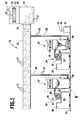
- FIG. 1 A preferred embodiment of an extraction system according to the invention is in FIG. 1 shown schematically and overall occupied by the reference numeral 10.
- the extraction system 10 comprises a housing 11, which receives a central suction unit 12 which is rotationally driven by means of a drive 13.
- a negative pressure can be generated in a central dirt collecting container 14 formed by the housing 11 so that suction material 17 can be sucked in via a suction line 15 connected to a suction opening 15 of the dirt collecting container 14 and deposited in the central dirt collecting container 14.
- the central suction unit 12 is preceded by a filter 18, which can be traversed by suction. Through an outlet 19, the suction air can leave the housing 11.
- the extraction system 10 is used for the extraction of suction material 17 arising from machine tools, of which in the present case two machine tools 20 are shown standing on a floor 21.
- a workpiece 22 can be machined by using a processing member 23.
- the machine tools 20 may be e.g. to deal with separating machine tools, especially woodworking machines.
- the workpiece 22 is, for example, a piece of wood and the processing member 23 is a woodworking device, for example a sawing unit.
- it is in the processing of the workpiece 22 accumulating suction 17 to wood chips or wood dust.
- the suction unit 10 comprises for sucking off the respective suction material 17 accumulating on a processing member 23, in each case a suction head 24 having a hood 25 which overlaps the processing member 23 and the workpiece 22.
- a short suction line 26 connects to the hood 25.
- the suction line 26 is connected with its end facing away from the hood 25 on the input side to a first preferred embodiment of a suction device 27 according to the invention and positioned directly next to the machine tool 20, namely at its suction inlet 28.
- the suction system 10 comprises two identically designed suction devices 27.
- a suction line 29 is connected to the suction outlet 30, which is connected with its suction outlet 30 remote from the end to the suction line 16. In this way, suction material 17 accumulating on the processing device 23 can be sucked through the suction line 26, the suction device 27, the suction line 29 and the suction line 16 and deposited in the central dirt collecting container 14.
- the extraction system 10 comprises a schematically illustrated control device 31, whose operation will be explained below.
- the suction device 27 comprises a housing 32, which receives a suction unit 33 which is rotationally driven by a drive 34. Below the suction unit 33, a filter 35 is held for sucked by the suction unit 33 suction air, and the suction air can leave the housing 32 via an outlet 36.
- the housing 32 On its underside, the housing 32 carries a plurality of rollers 37, so that the suction device 27 can be moved on the floor 21 in a user-friendly manner and can be positioned relative to the machine tool 20 as required.
- the housing 32 forms a two-part container 38, namely with a first dirt collecting container 39 and a second dirt collecting container 40 arranged below it.
- the dirt collecting containers 39 and 40 share a common wall 41, which forms a funnel-shaped bottom wall of the first dirt collecting container 39 and in which a first passage opening 42 for suction material 17 is formed.
- the first dirt collecting container 39 has the suction inlet 28, and the second dirt collecting container 41 has the suction outlet 30.
- the suction outlet 30 forms a second passage opening 43 for suction material 17.
- the second dirt collecting container 40 has a forced air inlet 44 with an inflow opening 45 for ambient air.
- a first obturator 46 is arranged, which is designed in the form of a closing device with a closing element in the form of a flap 47.
- the first passage opening 42 can optionally be closed and released, this defines a closed position or a release position of the flap 47. If the flap 47 assumes its closed position, no suction material 17 can pass through the first passage opening 42. This is referred to as the blocking state of the obturator 46. If, on the other hand, the flap 47 assumes its release position, the suction material 17 can pass from the first dirt collecting container 39 into the second dirt collecting container 40, passing through the first through opening 42. This defines an on-state of the first obturator 46. In FIGS Figures 2 . 4 and 5 the flap 47 assumes its closed position, and in FIG. 3 the flap 47 takes its release position.
- the first obturator 46 comprises an actuator in the form of a particular pneumatic actuator 48 for the flap 47.
- pneumatic actuator 48 could also be a mechanical, an electrical, a hydraulic or other kind of drive used.
- a second obturator 49 is arranged, which is likewise designed in the form of a closing device with a closing element in the form of a slide 50.
- the second passage opening 43 is selectively releasable and closable. If the slide 50 assumes its closed position, no suction material 17 can pass through the second passage 43 ( FIGS. 2 to 4 ). This defines a blocking state of the obturator 49. On the other hand, if the slider 50 assumes its release position, suction material 17 can pass through the second through-opening 43 to step ( FIG. 5 ). This defines an on-state of the obturator 49.
- the obturator 49 comprises a likewise designed as a particular pneumatic drive drive 51st
- a third obturator 52 is arranged on the outside air inlet 44, which is designed in the form of a closing device with a closing element in the form of a slide 53.
- the inflow opening 45 can be closed ( FIGS. 2 to 4 ), this defines a closed position of the slide 53 and a blocking state of the third obturator 52. If the inflow opening 45 is released ( FIG. 5 ), foreign air can flow through the inflow opening 45 into the second dirt collecting container 40. This defines a release position of the slider 53 and an on-state of the third obturator 52.
- the third obturator 52 comprises a likewise designed as a particular pneumatic drive drive 54th
- the drives 48, 51 and 54 are connected via control lines 55, 56 and 57 with a control device 58 of the suction device 27 in operative connection.
- the control lines 55 to 57 are for reasons of clarity only in FIG. 2 and there only slightly.
- the control device 58 can be actuated by the control device 31 of the extraction system 10 via a control line 59 that is shown in the form of a block.
- the drives 48, 51 and 54 can be controlled in the manner described below, so that suction material 17 from the processing member 23 by means of the suction device 27 and the suction system 10 can be sucked in total.
- the suction unit 33 of the suction device 27 is preferably continuously in operation to the first dirt collecting 39 continuously with negative pressure to act on. Since the suction device 27 is arranged directly next to the machine tool 20, suction material 17 accumulated at the processing member 23 via the suction line 26 can be effectively detected with high flow velocity and sucked into the first dirt collecting container 39. At a first time ( FIG. 2 ) take the flap 47 and the slide 50 and 53 each a closed position.
- the control device 58 to drive the drive 48 to move the flap 47 in the release position.
- suction material 17 can fall from the first dirt collecting container 39 into the second dirt collecting container 40 through the first through opening 42 under the influence of gravity.
- the flap 47 is configured only impervious to suction, but not pressure-tight, there is a total of the same pressure when opening the flap 47 in the container 38, which facilitates the opening of the flap 47.
- control device 58 can drive the drive 48 to transfer the flap 47 back into the closed position ( FIG. 4 ).
- control device 58 can drive the drives 51 and 54 such that the slides 50 and 53 are each transferred to their release position ( FIG. 5 ).
- the dirt collecting container 40 is acted upon by the inflow opening 45 incoming external air. This results in the dirt collecting container 40, an air flow, so that the suction material 17 can be effectively sucked through the central suction unit 12.
- the first passage opening 42 is closed with the flap 47. This ensures that no suction material 17 is sucked from the second dirt collecting container 40 back into the first dirt collecting container 39 by means of the suction unit 33.
- the drives 51 and 54 can be controlled again by the control device 58 in such a way that the slides 50 and 53 assume their closed positions ( FIG. 2 ), and the cycle described above may begin again.
- the times at which by means of the control device 58, the drives 48, 51 and 54 are actuated to actuate the flap 47 and the slide 50 and 53, for example, can be preset and / or adjustable. An adjustment of these times as well as the time period during which the flap 47 and the sliders 50 and 53 are opened, can be made for example by a service staff for the suction device 27.
- the drives 48, 51 and 54 are driven depending on demand, depending on the amount of suction material 17 in the first dirt collecting 39 and / or in the second dirt collecting 40.
- the suction device 27 a have corresponding sensor device to detect the amount of suction material 17.
- control device 58 is actuated via the control line 59 by the control device 31 of the suction system 10.
- the control device 31 can the control device 58 opening and closing time and duration of the closed positions and the release orders the flap 47 and the slide 50 and 53 pretend.
- the extraction system 10 comprises more than just a suction device 27, it is possible, in particular, for the suction devices 27 to be sucked off one after the other by means of the central suction unit 12, ie the respective slides 50 of the suction devices 27 are actuated in a time-shifted manner so that the central suction unit 12 only has suction material 17 from each one of the second dirt collecting container 40 sucks ( FIG. 1 ).
- suction material 17 can be effectively detected on the machine tool 20 and transferred to the further components of the suction system 10 via the second dirt collecting container 40 forming a lock.
- This makes it possible to operate the extraction system 10 with a smaller power and with a smaller energy requirement than is the case with the suction systems known from the prior art.
- the performance of the central suction unit 12 can be reduced and the length and the diameter of the suction line 16 and the suction line 29 can be reduced compared to conventional extraction systems.
- suction devices can be used in the suction system 10 instead of the suction device 27.
- FIG. 6 A second preferred embodiment of a suction device according to the invention is in FIG. 6 shown schematically and there occupied by the reference numeral 60.
- the first dirt collecting container 39 has no wall 41 forming the passage opening 42, but the first passage opening 42 is formed over the entire cross-sectional area of the container 38.
- the second passage opening 43 is likewise formed over the entire cross-sectional area of the container 38.
- the second dirt collecting container 40 are divided into a first space area 61 below the first dirt collecting container 39 and a second space area 62 below the first space area 61, which open into one another via the second passage opening 43.
- the first obturator 46 comprises as a closing element a relative to the container 38 horizontally displaceable slide 63 for closing the first passage opening 42.
- the second obturator 49 comprises a relative to the container 38 horizontally displaceable slide 64 for closing the second passage opening 43.
- Saugauslass 30th even no obturator is arranged.
- the forced air inlet 44 and the third shut-off device 52 are arranged on the container 38 such that the inflow opening 45 is arranged in the region of the first space region 61.
- the suction material 17 can be sucked out of the first space region 61 through the second space region 62 by means of the central suction unit 12 ,
- FIG. 6 shows the suction device in one of FIG. 3 corresponding representation in which the slide 63 occupies a release position and the first passage opening 42 is partially released.
- FIG. 7 A third preferred embodiment of a suction device according to the invention is in FIG. 7 shown schematically and there occupied by the reference numeral 65.
- the container 38 with a flexible tubular structure, hereinafter referred to as tube 66 lined.
- the hose 66 is embraced below the suction inlet 28 by a closing element of the first obturator 46 in the form of a loop 67, for example of wire.
- the hose 66 surrounded by a closing element of the second obturator 49 in the form of another, similar loop 68 between the loop 67 and the suction outlet 30. He forms each section a wall of the dirt collection 39 and 40th
- the cross-section of the hose 66 enclosed by the loops 67 and 68 defines the first passage opening 42 and the second passage opening 43, respectively. Accordingly, the second dirt collecting enclosure 40 is subdivided into a first space area 69 between the loops 67 and 68 and into a second space area 70 below Sling 68.
- the tube 66 can be contracted so far that the first passage opening 42 and the second passage opening 43 disappear completely, i. are closed.
- the loop 67 and the loop 68 can be loosened so that the flexible tube 66 expands and the first passage opening 42 and the second passage opening 43 are present, i. E. are released by means of loops 67 and 68 respectively.
- the drives 48 and 51 for the loops 67 and 68 are preferably mechanical drives.
- FIG. 7 shows the suction device 65 in one of FIG. 3 corresponding representation in which the first passage opening 42 is released by means of the loop 67 and the second passage opening 43 is closed by means of the loop 68.
- the suction device 65 works in accordance with the suction device 60 and thus largely as the suction device 27, so that reference may be made to the above explanations.
- FIG. 8 A fourth preferred embodiment of a suction device according to the invention is in FIG. 8 shown schematically and there occupied by the reference numeral 71.
- the suction device 71 the dirt collecting containers 39 and 40 are separated from each other by a horizontal wall 72 forming the first passage 42.
- a shut-off device 73 is used, which as a conveyor with a conveyor element in the form of a rotary valve 74 is formed.
- the rotary valve 74 is rotatable about a horizontal axis lying in a plane defined by the wall 72 and comprises a plurality of cells 75.
- a funnel-shaped wall 76 is arranged in the first dirt collecting container 39, with which the suction material 17 can be led into one of the cells 75.
- the rotary valve 74 is actuated by means of a drive 77, in this case a mechanical drive. This drive 77 can be controlled by the control device 58 in the same way as the drive 48.
- suction material 17 can be conveyed out of the first dirt collecting container 39 into the second dirt collecting container 40. This happens because suction material 17 passes through an opening 78 formed in the wall 76 and enters one of the cells 75 and that in subsequent rotation of the rotary valve 74, the filled with suction material 17 cell 75 is emptied into the second dirt collecting container 40 under the influence of gravity ,
- the rotary valve 74 does not rotate, this defines a blocking state of the first obturator 73. In this case, no suction material 17 can pass through the passage opening 42. On the other hand, if the rotary valve 74 rotates, the suction material 17 can pass through the first passage opening 42, and this defines a passage state of the first shut-off device 73.
- the rotary valve 74 rotates permanently during operation of the suction device 71, ie permanently assumes the on-state. Accordingly, suction material 17 is continuously conveyed from the first dirt collecting container 39 into the second dirt collecting container 40. In this case, the first obturator 73 is transferred, for example, only during the commissioning of the suction device 71 from the locked state to the on-state and transferred when disabling the suction device 71 from the on state to a blocking state.
- the rotary valve 74 rotates only temporarily and conveys the content of suction material 17 of a predeterminable number of cells 75 in the second dirt collecting 40 before this amount of suction material 17 is then sucked out of the second dirt collecting 40.
- the suction device 71 functions in a similar manner as the suction device 27, so that reference may be made to the above explanations.
- FIG. 9 A fifth preferred embodiment of a suction device according to the invention is in FIG. 9 shown schematically and there occupied by the reference numeral 79.
- the suction device 79 is formed substantially identical to the suction device 71 and, like this, comprises the first obturator 73, which is designed as a conveying device with the conveying element in the form of the rotary valve 74.
- the rotary valve 74 is rotatable at the suction device 79 about a vertical and perpendicular to a plane defined by the wall 72 level axis.
- the rotary valve 74 can be rotated continuously. It is also possible that the rotary valve 74 is only temporarily rotated, wherein between each successive rotations of the rotary valve 74 each collected in the second dirt collecting 40 suction material 70 can be sucked.
- the suction device 79 functions in a similar manner as the suction device 71, so that reference can be made to the above explanation and thus also to the explanation concerning the suction device 27.
- FIG. 10 is a sixth preferred embodiment of a suction device according to the invention shown schematically and there occupied by the reference numeral 80.
- the suction device 80 is a variant of the suction device 27, in which, instead of the shut-off elements 49 and 52, a common shut-off element 81, which unites their function, is used.
- the obturator 81 is accordingly designed in the form of a closing device with a closing element in the form of a slide 82.
- the slide 82 is actuated by means of a drive and in particular pneumatic drive 83.
- the spool 82 closes the inflow opening 45 and the second passage opening 43, and in a release position (not shown) the slide 82 releases the inflow opening 45 and the second passage opening 43.
- the drive 83 can be controlled by the control device 58 in a manner corresponding to that of the drive 51.
- the suction device 80 works in a similar manner as the suction device 27, so that reference can be made to the above explanations.
- a seventh preferred embodiment of a suction device according to the invention is in FIG. 11 shown schematically and there occupied by the reference numeral 84.
- the suction device 84 is substantially identical to the suction device 27. This differs from it in that it is subdivided into a first device unit 85 and a second device unit 86, which are detachably connectable to each other and can be pressure-tightly interconnected by means of suitable connecting elements 87.
- the second device unit 86 comprises that region of the suction device 84, insofar as it is located below the extension of the funnel-shaped wall 41 on the housing 32, ie also a section of the first dirt collection container 39 arranged below the suction inlet 28.
- the first device unit 85 can be solved and on an in FIG. 12 shown third unit unit 88 are placed.
- the third unit unit 88 forms a cup-shaped and upwardly open container 89 with rollers 90 held on the underside.
- the first unit unit 85 can be pressure-tightly connected to the third unit 88 via the connecting elements 87, so that the remaining portion of the first unit 85 remains first dirt collecting container 39 and the container 89 form a common large dirt collector 91.
- the suction device provided with the reference numeral 92 formed in this way is a conventional suction device in the form of a vacuum cleaner, which can be moved by means of rollers 90 on the floor 21.
- the suction device 84 in combination with the third unit unit 88 proves to be very flexible, because it can not only be sucked off for sucking the accumulator 23 accumulating suction 17, but also finds applications as a conventional vacuum cleaner.
Abstract
Description
Die Erfindung betrifft ein Sauggerät zum Absaugen eines Bearbeitungsorgans einer Werkzeugmaschine.The invention relates to a suction device for sucking off a processing member of a machine tool.
Außerdem betrifft die Erfindung eine Absauganlage für mindestens eine Werkzeugmaschine.Moreover, the invention relates to a suction for at least one machine tool.
Im Anwendungsbereich trennender Werkzeugmaschinen, wie sie beispielsweise in der Holzbearbeitung eingesetzt werden, sind Absauganlagen bekannt mit einem zentralen Saugaggregat, mit dem eine Hauptabsaugleitung mit Unterdruck beaufschlagt wird. An die Hauptabsaugleitung sind über Zweigleitungen Saugköpfe parallel zueinander angeschlossen, mit denen jeweils an Bearbeitungsorganen der Werkzeugmaschinen anfallendes Sauggut abgesaugt werden kann. Um sicherzustellen, dass das Sauggut wirkungsvoll abgesaugt werden kann, ist es erforderlich, das zentrale Saugaggregat mit hoher Saugleistung bereitzustellen. Ferner ist es vonnöten, die Hauptabsaugleitung und die Zweigleitungen mit großen Querschnitten zu versehen, typischerweise mit Durchmessern von 70 cm bzw. 30 cm. Aufgrund der großen Leitungsquerschnitte entstehen trotz leistungsstarkem zentralen Saugaggregat erhebliche Leistungsverluste, wodurch die Strömungsgeschwindigkeit in den Absaugleitungen absinkt. Dies führt zu einer schlechten Erfassung von Sauggut an den Bearbeitungsorganen. Die Werkstücke müssen nachgesäubert werden, was zu erhöhten Betriebs- und Produktionskosten führt. Des Weiteren erweisen sich die vorstehend beschriebenen Absauganlagen aufgrund der groß zu dimensionierenden Absaugleitungen als schlecht handhabbar und als unflexibel, beispielsweise wenn eine Werkzeugmaschine zu versetzen ist.In the field of application of separating machine tools, such as those used in woodworking, extraction systems are known with a central suction unit, with which a Hauptabsaugleitung is subjected to negative pressure. Suction heads are connected in parallel to one another via branch lines to the main suction line, with which suction material accumulating on processing elements of the machine tools can be sucked off. To ensure that the suction material can be effectively extracted, it is necessary to provide the central suction unit with high suction power. Furthermore, it is necessary to provide the main suction line and the branch lines with large cross-sections, typically with diameters of 70 cm and 30 cm, respectively. Due to the large cable cross-sections, despite the powerful central suction unit, considerable power losses occur, as a result of which the flow velocity in the suction lines drops. This leads to a poor detection of suction material on the processing organs. The workpieces must be cleaned, which leads to increased operating and production costs. Furthermore, due to the large suction lines to be dimensioned, the extraction systems described above prove to be difficult to handle and inflexible, for example when a machine tool is to be displaced.
Um einigen der vorstehend genannten Probleme abzuhelfen, schlägt die
In der
Aufgabe der vorliegenden Erfindung ist es, ein Sauggerät sowie eine Absauganlage bereitzustellen, mit dem bzw. der eine verbesserte Absaugung von Sauggut an einem Bearbeitungsorgan einer Werkzeugmaschine unter geringeren Anforderungen an die Leistung und den Energiebedarf der Absauganlage ermöglicht wird.Object of the present invention is to provide a suction device and a suction, with the or the improved suction of suction material to a processing member of a machine tool with lower demands on the performance and energy consumption of the extraction system is made possible.
Diese Aufgabe wird durch ein erfindungsgemäßes Sauggerät gelöst, das einen ersten Schmutzsammelbehälter umfasst mit einem Saugeinlass für am Bearbeitungsorgan anfallendes Sauggut und mit einer ersten Durchtrittsöffnung für Sauggut, sowie ein Saugaggregat, um den ersten Schmutzsammelbehälter mit Unterdruck zu beaufschlagen, ein erstes Absperrorgan, das von einem Sperrzustand, in dem ein Durchtritt von Sauggut durch die erste Durchtrittsöffnung verhindert wird, in einen Durchlasszustand, in dem Sauggut durch die erste Durchtrittsöffnung hindurch treten kann, und umgekehrt überführbar ist, einen zweiten Schmutzsammelbehälter zur Aufnahme von die erste Durchtrittsöffnung durchtretendem Sauggut mit einem Saugauslass, an den eine Absaugleitung einer Absauganlage anschließbar und über den der zweite Schmutzsammelbehälter mit Unterdruck beaufschlagbar ist, und mit einer zweiten Durchtrittsöffnung für Sauggut sowie ein zweites Absperrorgan, welches von einem Sperrzustand, in dem ein Durchtritt von Sauggut durch die zweite Durchtrittsöffnung verhindert wird, in einen Durchlasszustand, in dem Sauggut durch die zweite Durchtrittsöffnung hindurch treten kann, und umgekehrt überführbar ist.This object is achieved by an inventive suction device comprising a first dirt collecting container with a suction inlet for accumulating on the processing member suction and a first passage for suction material, and a suction unit to pressurize the first dirt collecting container with a negative pressure, a first obturator of a Blocking state, in which a passage of suction material is prevented by the first passage opening, in a passage state in which suction material can pass through the first passage opening, and vice versa, a second dirt collecting container for receiving the first passage opening passing through the suction with a suction outlet, can be connected to the suction line of a suction and over which the second dirt collecting container can be acted upon with negative pressure, and with a second passage for suction and a second obturator, which from a blocking state, in a passage of suction material is prevented by the second passage opening, in a passage state in the suction material can pass through the second passage opening, and vice versa can be transferred.
Das erfindungsgemäße Sauggerät kommt zur Unterstützung der Absauganlage beim Absaugen von am Bearbeitungsorgan anfallenden Sauggut zum Einsatz. Das Sauggerät kann in unmittelbarer Umgebung der Werkzeugmaschine platziert werden. Dies gibt die Möglichkeit, unter Einsatz einer an den Saugeinlass des ersten Schmutzsammelbehälters anschließbaren verhältnismäßig kurzen Saugleitung mit geringem Durchmesser, beispielsweise 10 cm, wirkungsvoll Sauggut am Bearbeitungsorgan zu erfassen und in den ersten Schmutzsammelbehälter einzusaugen. Dieser wird durch das Saugaggregat mit Unterdruck beaufschlagt. Nimmt das erste Absperrorgan den Sperrzustand ein, bei dem ein Hindurchtreten von Sauggut durch die erste Durchtrittsöffnung verhindert wird, kann Sauggut im ersten Schmutzsammelbehälter angesammelt werden. Wird das erste Absperrorgan in den Durchlasszustand überführt, kann das Sauggut durch die erste Durchtrittsöffnung hindurch in den zweiten Schmutzsammelbehälter gelangen und darin angesammelt werden, wenn das zweite Absperrorgan den Sperrzustand einnimmt. Wird das zweite Absperrorgan in den Durchlasszustand überführt, kann aufgrund des vom zentralen Saugaggregat erzeugbaren Unterdruckes das im zweiten Schmutzsammelbehälter angesammelte Sauggut durch die zweite Durchtrittsöffnung hindurch treten und von der Absauganlage abgesaugt werden.The suction device according to the invention is used to support the suction during the suction of accumulating on the processing device suction. The suction device can be placed in the immediate vicinity of the machine tool. This makes it possible, by using a connectable to the suction inlet of the first dirt collection container relatively short suction line with a small diameter, for example, 10 cm, to effectively capture suction material on the processing unit and sucked into the first dirt collecting. This is acted upon by the suction unit with negative pressure. If the first obturator adopts the blocking state in which a passage of suction material through the first passage opening is prevented, suction material can be accumulated in the first dirt collecting container. If the first obturator is transferred to the on-state, the suction material can pass through the first passage opening into the second dirt collecting container and be accumulated therein when the second obturator assumes the blocking state. If the second obturator is transferred to the on-state, due to the negative pressure generated by the central suction unit, the accumulated in the second dirt collecting suction material can pass through the second passage opening and be sucked by the suction.
Der zweite Schmutzsammelbehälter dient somit gewissermaßen als Schleuse, über die Sauggut aus dem ersten Schmutzsammelbehälter an die Absaugleitung der Absauganlage übergeben werden kann. Die Übergabe von Sauggut findet am Saugauslass des Sauggerätes statt. Dies erlaubt es, die Absaugleitung kürzer auszubilden als bei einer bekannten Absauganlage. Infolgedessen wird die vom zentralen Saugaggregat der Absauganlage zu bewegende Luftmenge verringert. Das zentrale Saugaggregat kann damit kleiner dimensioniert werden als bei einer herkömmlichen Absauganlage, und die Anforderungen an die Leistung und an den Energiebedarf der Absauganlage werden verringert.The second dirt collector thus effectively serves as a lock, can be passed over the suction material from the first dirt collector to the suction of the suction. The transfer of suction material takes place at the suction outlet of the suction device. This makes it possible to make the suction shorter than in a known extraction system. As a result, the amount of air to be moved from the central suction unit of the exhaust system is reduced. The central suction unit can thus be dimensioned smaller than in a conventional extraction system, and the requirements for the performance and the energy consumption of the extraction system are reduced.
Zum Entleeren des ersten Schmutzsammelbehälters ist es ferner nicht erforderlich, das Sauggerät abzuschalten, da die Übergabe von Sauggut an die Absauganlage im laufenden Betrieb des Sauggerätes erfolgen kann. Insbesondere kann der erste Schmutzsammelbehälter mittels des Saugaggregates kontinuierlich mit Unterdruck beaufschlagt werden, um dauerhaft Sauggut am Bearbeitungsorgan zu erfassen.For emptying the first dirt collecting container, it is also not necessary to switch off the suction device, since the transfer of suction material to the suction can be done during operation of the suction device. In particular, the first dirt collecting container can be acted upon continuously by means of the suction unit with negative pressure in order to permanently detect suction material on the processing member.
Mit dem erfindungsgemäßen Sauggerät lässt sich auch das Versetzen einer Werkzeugmaschine einfacher gestalten als bei den bekannten Absauganlagen. Die Werkzeugmaschine kann zusammen mit dem in seiner unmittelbaren Umgebung platzierbaren Sauggerät neu positioniert werden. Die verhältnismäßig geringe Länge der Saugleitung vom Bearbeitungsorgan zum Saugeinlass kann beibehalten werden, so dass der Erfassungsgrad von Sauggut am Bearbeitungsorgan weiterhin hoch ist.With the suction device according to the invention, the displacement of a machine tool can be made simpler than in the known extraction systems. The machine tool can be repositioned together with the suction device which can be placed in its immediate vicinity. The relatively small length of the suction line from the processing member to the suction inlet can be maintained, so that the detection rate of suction material on the processing device is still high.
Günstig ist es, wenn die erste Durchtrittsöffnung eine Eintrittsöffnung für Sauggut in den zweiten Schmutzsammelbehälter bildet, denn dies ermöglicht eine einfache konstruktive Ausgestaltung des Sauggerätes. Die Schmutzsammelbehälter können eine gemeinsame Wand aufweisen, in der die Durchtrittsöffnung gebildet ist.It is advantageous if the first passage opening forms an inlet opening for suction material in the second dirt collecting container, because this allows a simple structural design of the suction device. The dirt collecting container may have a common wall in which the passage opening is formed.
Bevorzugt ist die zweite Durchtrittsöffnung am Saugauslass angeordnet oder durch diesen ausgebildet. Dies ermöglicht ebenfalls eine einfache konstruktive Ausgestaltung des Sauggerätes. Das zweite Absperrorgan lässt sich konstruktiv einfach am Saugauslass anordnen.Preferably, the second passage opening is arranged at the suction outlet or formed by this. This also allows a simple structural design of the suction device. The second obturator can be arranged structurally simple at Saugauslass.
Es kann alternativ vorgesehen sein, dass die zweite Durchtrittsöffnung in Abstand zum Saugauslass angeordnet ist und dass über die zweite Durchtrittsöffnung ein erster Raumbereich des zweiten Schmutzsammelbehälters in einen zweiten Raumbereich des zweiten Schmutzsammelbehälters mündet, wobei Sauggut über die erste Durchtrittsöffnung in den ersten Raumbereich eintreten und über den Saugauslass aus dem zweiten Raumbereich austreten kann.It may alternatively be provided that the second passage opening is arranged at a distance from the suction outlet and that a first space region of the second dirt collection container opens into a second space region of the second dirt collection container via the second passage opening, wherein suction material enters via the first passage opening into the first space region and over can exit the Saugauslass from the second room area.
Durch die erste Durchtrittsöffnung hindurch tretendes Sauggut kann im ersten Raumbereich des zweiten Schmutzsammelbehälters gesammelt werden, wenn das zweite Absperrorgan den Sperrzustand einnimmt. Nach dem Überführen des zweiten Absperrorgans in den Durchlasszustand kann das gesammelte Sauggut von der Absauganlage durch den Saugauslass und die zweite Durchtrittsöffnung hindurch abgesaugt werden.Suction material passing through the first passage opening can be collected in the first space region of the second dirt collection container when the second shut-off element assumes the blocking state. After transferring the second obturator in the on-state, the collected suction material can be sucked from the suction through the suction outlet and the second passage opening therethrough.
Von Vorteil ist es, wenn der zweite Schmutzsammelbehälter einen Einlass für Fremdluft umfasst und wenn das Sauggerät ein drittes Absperrorgan aufweist, das von einem Sperrzustand, in dem der Einlass verschlossen ist, in einen Durchlasszustand, in dem die Einlass geöffnet ist, und umgekehrt überführbar ist. Durch den Einlass kann Fremdluft in den zweiten Schmutzsammelbehälter einströmen. Nimmt das zweite Absperrorgan währenddessen den Durchlasszustand ein, kann sich eine Luftströmung durch den zweiten Schmutzsammelbehälter hindurch ausbilden. Dies erleichtert das Absaugen von Sauggut aus dem zweiten Schmutzsammelbehälter.It is advantageous if the second dirt collecting container comprises an inlet for external air and if the suction device has a third obturator, which can be converted from a blocking state in which the inlet is closed, in an open state in which the inlet is open, and vice versa , External air can flow into the second dirt collector through the inlet. Meanwhile, when the second obturator enters the on-state, an airflow may be formed through the second debris collection container. This facilitates the suction of suction material from the second dirt collecting.
Alternativ hat es sich als günstig erwiesen, wenn der zweite Schmutzsammelbehälter einen Einlass für Fremdluft umfasst, der mittels des den Sperrzustand einnehmenden zweiten Absperrorgans verschlossen wird und geöffnet ist, wenn das zweite Absperrorgan den Durchlasszustand einnimmt. Dies ermöglicht eine einfachere konstruktive Ausgestaltung des Sauggerätes. Mittels des zweiten Absperrorgans kann dann sowohl ein Durchtritt von Sauggut durch die zweite Durchtrittsöffnung verhindert oder ermöglicht werden als auch ein Einströmen von Fremdluft verhindert oder ermöglicht werden.Alternatively, it has proved to be advantageous if the second dirt collecting container comprises an inlet for external air, which is closed by means of the blocking state engaging second obturator and is open when the second obturator assumes the on state. This allows a simpler structural design of the suction device. By means of the second obturator can then be prevented or made possible both a passage of suction material through the second passage opening as well as an influx of foreign air can be prevented or made possible.
Es kann vorgesehen sein, dass durch den Einlass Fremdluft atmosphärischen Drucks in den zweiten Schmutzsammelbehälter eintreten kann. Es ist auch möglich, dass der zweite Schmutzsammelbehälter über den Einlass mit Fremdluft mit Überdruck, d.h. mit einem über dem atmosphärischen Druck liegenden Druck, beaufschlagt wird.It can be provided that external air of atmospheric pressure can enter the second dirt collecting container through the inlet. It is also possible that the second dirt collecting container is acted upon by the inlet with external air with overpressure, ie with a pressure above the atmospheric pressure.
Für einen zuverlässigen Betrieb des Sauggerätes hat es sich als günstig erweisen, wenn mindestens ein Absperrorgan eine Betätigungseinrichtung zum Überführen des Absperrorgans vom Sperrzustand in den Durchlasszustand und/oder umgekehrt aufweist.For a reliable operation of the suction device, it has proved to be advantageous if at least one obturator has an actuating device for transferring the obturator from the blocking state into the on-state and / or vice versa.
Vorteilhafterweise ist mindestens eine Betätigungseinrichtung als pneumatischer Antrieb ausgebildet. Dies hat sich in der Praxis als vorteilhaft für eine zuverlässige Funktion des jeweiligen Absperrorgans herausgestellt. Insbesondere können alle Betätigungseinrichtungen als pneumatische Antriebe ausgebildet sein.Advantageously, at least one actuating device is designed as a pneumatic drive. This has proven in practice to be advantageous for reliable operation of the respective obturator. In particular, all actuators may be designed as pneumatic actuators.
Bei andersartigen Ausführungsformen des erfindungsgemäßen Sauggerätes hat es sich als günstig erwiesen, wenn mindestens eine Betätigungseinrichtung als mechanischer, hydraulischer oder elektrischer Antrieb ausgebildet ist.In other embodiments of the suction device according to the invention, it has proven to be advantageous if at least one actuating device is designed as a mechanical, hydraulic or electric drive.
Es kann vorgesehen sein, dass mindestens eine Betätigungseinrichtung manuell durch einen Benutzer betätigbar ist.It can be provided that at least one actuating device can be actuated manually by a user.
Bevorzugt ist allerdings mindestens eine Betätigungseinrichtung von einer Steuereinrichtung ansteuerbar. Dies gibt auf einfache Weise die Möglichkeit, den Betrieb des Sauggerätes zu automatisieren und dadurch so anpassungsfähig wie möglich zu gestalten.Preferably, however, at least one actuating device can be controlled by a control device. This provides a simple way to automate the operation of the suction device and thereby make it as flexible as possible.
Vorteilhafterweise nehmen das erste Absperrorgan und das zweite Absperrorgan einander abwechselnd jeweils den Sperrzustand und den Durchlasszustand ein unter Anwendung von Steuersignalen, die einer ersten Betätigungseinrichtung des ersten Absperrorgans und einer zweiten Betätigungseinrichtung des zweiten Absperrorgans durch die Steuereinrichtung bereitstellbar sind. Dadurch kann auf einfache Weise sichergestellt werden, dass Sauggut zuverlässig zur Übergabe an die Absauganlage durch den zweiten Schmutzsammelbehälter hindurchgeschleust wird. Im ersten Schmutzsammelbehälter angesammeltes Sauggut kann in den zweiten Schmutzsammelbehälter gelangen, wenn das erste Absperrorgan von der Steuereinrichtung dahingehend angesteuert wird, dass es den Durchlasszustand einnimmt. Anschließend kann das zweite Absperrorgan dahingehend angesteuert werden, dass es den Durchlasszustand einnimmt, und das erste Absperrorgan kann dahingehend angesteuert werden, dass es wieder den Sperrzustand einnimmt. Im ersten Schmutzsammelbehälter kann weiterhin Sauggut angesammelt werden, und das Sauggut im zweiten Schmutzsammelbehälter kann der Absauganlage übergeben werden.Advantageously, the first obturator and the second obturator alternately take each other the blocking state and the on state by using control signals that are provided by a first actuating device of the first obturator and a second actuator of the second obturator by the control device. As a result, it can be ensured in a simple manner that suction material is reliably passed through the second dirt collecting container for transfer to the extraction system. Suction material accumulated in the first dirt collecting container can enter the second dirt collecting container when the first obturator of the control device to the effect is driven, that it assumes the on-state. Subsequently, the second obturator can be controlled so that it assumes the on-state, and the first obturator can be controlled so that it assumes the blocking state again. In the first dirt collecting container, suction material can continue to accumulate, and the suction material in the second dirt collecting container can be transferred to the extraction system.
Günstig ist es, wenn das erste Absperrorgan und das zweite Absperrorgan nicht gleichzeitig jeweils den Durchlasszustand einnehmen unter Anwendung von Steuersignalen, die der ersten Betätigungseinrichtung des ersten Absperrorgans und der zweiten Betätigungseinrichtung des zweiten Absperrorgans durch die Steuereinrichtung bereitstellbar sind. Dadurch, dass das erste Absperrorgan und das zweite Absperrorgan nicht gleichzeitig den Durchlasszustand einnehmen, kann eine gegenseitige Störung der Saugaggregate des Sauggerätes und der Absauganlage weitgehend vermieden werden. Insbesondere kann ein die Strömungsrichtung im Sauggerät umkehrendes unerwünschtes Druckgefälle zwischen dem Druck im zweiten Schmutzsammelbehälter und dem Druck im ersten Schmutzsammelbehälter weitgehend verhindert werden.It is advantageous if the first obturator and the second obturator do not simultaneously assume the passage state in each case using control signals which can be provided by the control device to the first actuation device of the first obturator and the second actuation device of the second obturator. Characterized in that the first obturator and the second obturator not simultaneously assume the on-state, a mutual interference of the suction units of the suction device and the suction system can be largely avoided. In particular, a reverse flow direction in the suction device undesirable pressure gradient between the pressure in the second dirt collecting container and the pressure in the first dirt collecting container can be largely prevented.
Bevorzugt nehmen das zweite Absperrorgan und das dritte Absperrorgan gleichzeitig jeweils den Durchlasszustand ein unter Anwendung von Steuersignalen, die der zweiten Betätigungseinrichtung des zweiten Absperrorgans und einer dritten Betätigungseinrichtung des dritten Absperrorgans durch die Steuereinrichtung bereitstellbar sind. Dadurch kann auf technisch einfache Weise sichergestellt werden, dass sich im zweiten Schmutzsammelbehälter eine Luftströmung ausbilden kann, um das Absaugen des Saugguts zu erleichtern, wenn das zweite Absperrorgan den Durchlasszustand einnimmt.Preferably, the second obturator and the third obturator at the same time each take the passage state using control signals that the second actuator of the second obturator and a third actuator of the third obturator are provided by the controller. As a result, it can be ensured in a technically simple manner that an air flow can form in the second dirt collecting container in order to facilitate the suction of the suction material when the second shut-off element assumes the on-state.
Vorteilhafterweise nehmen das erste Absperrorgan und das dritte Absperrorgan nicht gleichzeitig den Durchlasszustand ein unter Anwendung von Steuersignalen, die der ersten Betätigungseinrichtung des ersten Absperrorgans und der dritten Betätigungseinrichtung des dritten Absperrorgans durch die Steuereinrichtung bereitstellbar sind. Dadurch kann vermieden werden, dass in den zweiten Schmutzsammelbehälter einströmende Fremdluft mittels des Saugaggregates durch die erste Durchtrittsöffnung hindurch in den ersten Schmutzsammelbehälter angesaugt wird und so das Absaugen von Sauggut vom Bearbeitungsorgan beeinträchtigt wird.Advantageously, the first obturator and the third obturator do not simultaneously assume the on state by the use of control signals, the first actuator of the first obturator and the third actuator of the third obturator by the controller are available. It can thereby be avoided that foreign air flowing into the second dirt collecting container is sucked into the first dirt collecting container through the first through opening by means of the suction aggregate, thus impairing the suction of suction material by the processing member.
Bevorzugt ist mindestens ein Absperrorgan zeitgesteuert vom Sperrzustand in den Durchlasszustand und/oder umgekehrt überführbar unter Anwendung eines Steuersignals, das der Betätigungseinrichtung des Absperrorgans durch die Steuereinrichtung bereitstellbar ist. Dadurch kann ein zuverlässigerer Betrieb des Sauggerätes und infolgedessen ein zuverlässigeres Erfassen von Sauggut am Bearbeitungsorgan sichergestellt werden. In gewissen, beispielsweise einstellbaren Intervallen, kann mindestens ein Absperrorgan und bevorzugt alle Absperrorgane von dem Sperrzustand in den Durchlasszustand und/oder umgekehrt überführt werden.Preferably, at least one obturator is time-controlled from the blocking state into the on-state and / or conversely transferable using a control signal, which is the actuator of the obturator prepared by the control device. As a result, a more reliable operation of the suction device and consequently a more reliable detection of suction material on the processing device can be ensured. In certain, for example, adjustable intervals, at least one obturator and preferably all shut-off devices can be transferred from the blocking state to the on-state and / or vice versa.
Günstig ist es, wenn mindestens ein Absperrorgan in Abhängigkeit von der Menge an Sauggut in einem Schmutzsammelbehälter vom Sperrzustand in den Durchlasszustand und/oder umgekehrt überführbar ist unter Anwendung eines Steuersignals, das der Betätigungseinrichtung des Absperrorgans durch die Steuereinrichtung bereitstellbar ist. Auf diese Weise kann der Betrieb des Sauggerätes an die Menge an anfallendem Sauggut angepasst werden. Beispielsweise kann das Absperrorgan derart betätigt werden, dass die Menge an Sauggut in einem Schmutzsammelbehälter eine maximale Menge nicht überschreitet. Um die Menge an Sauggut in einem Schmutzsammelbehälter zu erfassen, kann das Sauggerät eine Sensoreinrichtung umfassen.It is advantageous if at least one obturator in dependence on the amount of suction material in a dirt collecting container from the blocking state in the on-state and / or vice versa can be converted using a control signal that the actuator of the obturator by the controller is provided. In this way, the operation of the suction device can be adapted to the amount of accumulated suction material. For example, the obturator can be actuated such that the amount of suction material in a dirt collecting container does not exceed a maximum amount. In order to detect the amount of suction material in a dirt collecting container, the suction device may comprise a sensor device.
Vorzugsweise umfasst das Sauggerät die Steuereinrichtung zum Ansteuern mindestens einer Betätigungseinrichtung.Preferably, the suction device comprises the control device for controlling at least one actuating device.
Ergänzend oder alternativ kann vorgesehen sein, dass dem Sauggerät eine Steuereinrichtung zur Ansteuerung mindestens einer Betätigungseinrichtung zugeordnet ist, die das Sauggerät selbst nicht umfasst. Hierbei handelt es sich insbesondere um eine zentrale Steuereinrichtung einer das Sauggerät umfassenden Absauganlage, welche sogar zur Ansteuerung der Betätigungseinrichtungen mehrerer Sauggeräte zum Einsatz kommen kann.Additionally or alternatively it can be provided that the suction device is assigned a control device for controlling at least one actuating device, which does not comprise the suction device itself. This is it in particular, a central control device of a suction device comprising the suction device, which can even be used to control the actuators of several suction devices used.
Es kann auch vorgesehen sein, dass das Sauggerät selbst eine Steuereinrichtung umfasst und diese ihrerseits auch noch von einer zentralen Steuereinrichtung der Absauganlage ansteuerbar ist.It can also be provided that the suction device itself comprises a control device and this in turn can also be controlled by a central control device of the suction system.
Bei einer konstruktiv einfachen Ausgestaltung des Sauggerätes ist mindestens ein Absperrorgan als Schließeinrichtung ausgebildet und umfasst ein Schließelement, mit dem eine Öffnung verschließbar ist. Das Schließelement nimmt in dem Sperrzustand des Absperrorgans eine Schließstellung ein und verschließt die Öffnung. Im Durchlasszustand des Absperrorgans nimmt das Schließelement eine Freigabestellung ein und gibt die Öffnung frei.In a structurally simple embodiment of the suction device, at least one obturator is designed as a closing device and comprises a closing element, with which an opening can be closed. The closing element assumes a closed position in the blocking state of the obturator and closes the opening. In the on state of the obturator, the closing element assumes a release position and releases the opening.
Von Vorteil ist es, wenn das Schließelement als Klappe oder als Schieber ausgebildet ist. Dies ermöglicht eine einfache konstruktive Ausgestaltung des Schließelementes und damit des Absperrorganes.It is advantageous if the closing element is designed as a flap or as a slide. This allows a simple structural design of the closing element and thus of the obturator.
Bei einer besonders günstigen Ausgestaltung des erfindungsgemäßen Sauggerätes hat es sich als vorteilhaft erwiesen, wenn das erste Absperrorgan als Schließeinrichtung mit einem Schließelement in Form einer Klappe ausgebildet ist, und das zweite und das dritte Absperrorgan sind Schließeinrichtungen mit Schließelementen in Form von Schiebern.In a particularly favorable embodiment of the suction device according to the invention, it has proved to be advantageous if the first obturator is designed as a closing device with a closing element in the form of a flap, and the second and the third obturator are closing devices with closing elements in the form of sliders.
Bei einer andersartigen Ausgestaltung eines Absperrorgans in Form einer Schließeinrichtung kann vorgesehen sein, dass das Schließelement als Pfropfen oder Deckel ausgebildet ist, um die Öffnung zu verschließen. Es ist auch möglich, dass das Schließelement als Schlinge ausgebildet ist, die eine flexible Wand eines Schmutzsammelbehälters umschließen und derart zusammenschnüren kann, dass ein Durchtritt von Sauggut durch den Schmutzsammelbehälter verhindert wird. Der von der Schlinge umgriffene Bereich des Schmutzsammelbehälters definiert gewissermaßen eine Durchtrittsöffnung, die mittels des Schließelementes wahlweise freigebbar und verschließbar ist.In a different embodiment of a shut-off device in the form of a closing device can be provided that the closing element is designed as a plug or lid to close the opening. It is also possible that the closing element is designed as a loop, which can enclose a flexible wall of a dirt collecting container and constrict such that a passage of suction material is prevented by the dirt collecting container. The area encompassed by the noose of the Dirt collection container defines a sort of passage opening, which is selectively releasable and closable by means of the closing element.
Von Vorteil ist es, wenn das erste Absperrorgan und/oder das zweite Absperrorgan als Fördereinrichtung ausgebildet ist und ein Förderelement umfasst, mit dem Sauggut durch die erste Durchtrittsöffnung bzw. die zweite Durchtrittsöffnung hindurch förderbar ist. Die Fördereinrichtung kann stillstehen, so dass das Absperrorgan den Sperrzustand einnimmt und eine Förderung von Sauggut durch die Durchtrittsöffnung hindurch nicht möglich ist. Im Betrieb der Fördereinrichtung kann Sauggut durch die Durchtrittsöffnung hindurch gefördert werden, was einen Durchlasszustand des Absperrorgans definiert.It is advantageous if the first obturator and / or the second obturator is designed as a conveying device and comprises a conveying element with which the suction material can be conveyed through the first passage opening or the second passage opening. The conveyor can stand still, so that the obturator assumes the blocking state and a delivery of suction material through the passage opening is not possible therethrough. During operation of the conveyor suction material can be conveyed through the passage opening, which defines a passage state of the obturator.
Es kann vorgesehen sein, dass die Fördereinrichtung beim Betrieb des Sauggerätes kontinuierlich betrieben wird, so dass kontinuierlich Sauggut durch die Durchtrittsöffnung hindurch förderbar ist. In diesem Fall kann das entsprechende Absperrorgan beispielsweise mit der Inbetriebnahme des Sauggerätes vom Sperrzustand in den Durchlasszustand und mit dem Abschalten des Sauggerätes vom Durchlasszustand in den Sperrzustand überführt werden.It can be provided that the conveyor is operated continuously during operation of the suction device, so that continuously suction material can be conveyed through the passage opening. In this case, the corresponding obturator, for example, with the commissioning of the suction device from the blocking state in the on state and with the shutdown of the suction device from the on state to the blocking state to be transferred.
Günstig ist es, wenn das Förderelement als Zellenradschleuse oder als Förderschnecke ausgebildet ist. Dies ermöglicht eine einfache konstruktive Ausgestaltung des Förderelementes und damit des Absperrorgans.It is advantageous if the conveying element is designed as a rotary feeder or as a screw conveyor. This allows a simple structural design of the conveying element and thus the obturator.
Bei einer bestimmten vorteilhaften Ausgestaltung des erfindungsgemäßen Sauggerätes hat es sich als günstig erweisen, wenn das erste Absperrorgan als Fördereinrichtung mit einem Förderelement in Form einer Zellenradschleuse ausgebildet ist, und wenn das zweite und das dritte Absperrorgan Schließeinrichtungen mit Schließelementen in Form von Schiebern sind.In a certain advantageous embodiment of the suction device according to the invention, it has proven to be advantageous if the first obturator is designed as a conveyor with a conveying element in the form of a rotary valve, and if the second and the third obturator closing devices with closing elements in the form of sliders.
Allgemein ist es günstig, wenn Sauggut unter Schwerkrafteinfluss vom ersten Schmutzsammelbehälter in den zweiten Schmutzsammelbehälter gelangen kann. Dies verleiht dem Sauggerät eine einfachere Konstruktion. Hierfür ist die erste Durchtrittsöffnung zweckmäßigerweise an einer Unterseite des ersten Schmutzsammelbehälters und beispielsweise in einer Bodenwand des ersten Schmutzsammelbehälters gebildet. Der zweite Schmutzsammelbehälter ist unterhalb des ersten Schmutzsammelbehälters angeordnet.In general, it is favorable if suction material can enter the second dirt collecting container under the influence of gravity from the first dirt collecting container. This gives the suction device a simpler construction. For this purpose, the first passage opening is expediently at an underside of the first Dirt collecting container and formed for example in a bottom wall of the first dirt collecting container. The second dirt collecting container is arranged below the first dirt collecting container.
Von Vorteil ist es, wenn das Sauggerät eine erste Geräteeinheit und eine mit dieser lösbar verbindbare zweite Geräteeinheit aufweist, wobei die erste Geräteeinheit zumindest das Saugaggregat und einen den Saugeinlass aufweisenden Abschnitt des ersten Schmutzsammelbehälters aufweist und wobei die zweite Geräteeinheit zumindest den zweiten Schmutzsammelbehälter und das zweite Absperrorgan aufweist. Dies gibt die Möglichkeit, die erste Geräteeinheit von der zweiten Geräteeinheit zu lösen. Die erste Geräteeinheit kann beispielsweise auf eine dritte Geräteeinheit aufgesetzt werden, welche einen herkömmlichen Schmutzsammelbehälter für Sauggut ausbildet. Vom Saugaggregat angesaugtes Sauggut kann in dem Schmutzsammelbehälter des auf diese Weise gebildeten Sauggerätes abgeschieden werden. Dadurch erweist sich das Sauggerät als flexibel, denn über den Einsatz an der Werkzeugmaschine hinaus kann es als herkömmlicher Staubsauger eingesetzt werden. Die dritte Geräteeinheit umfasst hierfür günstigerweise an der Unterseite angeordnete Rollen, so dass das dadurch gebildete Sauggerät auf einer Aufstellfläche verfahren werden kann.It is advantageous if the suction device has a first device unit and a detachably connectable with this second device unit, wherein the first unit unit comprises at least the suction unit and a suction inlet having portion of the first dirt collection container and wherein the second unit unit at least the second dirt collecting container and the second Has shut-off. This gives the possibility of detaching the first device unit from the second device unit. The first device unit can for example be placed on a third unit unit, which forms a conventional dirt collecting container for suction material. Suction material sucked by the suction unit can be deposited in the dirt collecting container of the suction device formed in this way. Thus, the suction device proves to be flexible, because in addition to the use of the machine tool, it can be used as a conventional vacuum cleaner. For this purpose, the third unit unit conveniently comprises rollers arranged on the underside, so that the suction device formed thereby can be moved on an installation surface.
Vorteilhafterweise umfasst die zweite Geräteeinheit zusätzlich das erste Absperrorgan und gegebenenfalls eine die erste Durchtrittsöffnung einfassende Wand des ersten Schmutzsammelbehälters. Die wesentlichen, die "Schleuse" für Sauggut des erfindungsgemäßen Sauggerätes ausmachenden Bauteile werden dadurch in der zweiten Geräteeinheit zusammengefasst.Advantageously, the second appliance unit additionally comprises the first obturator and optionally a wall of the first debris collecting vessel enclosing the first passage opening. The essential, the "lock" for suction of suction device of the invention constituting components are thus summarized in the second unit.
Wie eingangs erwähnt, betrifft die Erfindung auch eine Absauganlage für mindestens eine Werkzeugmaschine. Die eingangs gestellte Aufgabe wird durch eine erfindungsgemäße Absauganlage gelöst, die mindestens ein Sauggerät der vorstehend beschriebenen Art umfasst sowie ein zentrales Saugaggregat, einen von diesem mit Unterdruck beaufschlagbaren zentralen Schmutzsammelbehälter, der eine Saugöffnung aufweist, sowie mindestens eine Absaugleitung, die an die Saugöffnung und an den Saugauslass des mindestens einen Sauggerätes angeschlossen ist.As mentioned above, the invention also relates to an exhaust system for at least one machine tool. The object stated in the introduction is achieved by an extraction system according to the invention which comprises at least one suction device of the type described above, and a central suction unit, a central dirt collecting container which can be acted upon by the latter with negative pressure and which has a suction opening, and at least one suction line. which is connected to the suction opening and to the suction outlet of the at least one suction device.
Die erfindungsgemäße Absauganlage weist dann die bereits im Zusammenhang mit der Erläuterung des erfindungsgemäßen Sauggerätes beschriebenen Vorteile auf. Auch die mit den vorteilhaften Ausgestaltungen des Sauggerätes erzielbaren Vorteile lassen sich mit der Absauganlage erzielen.The extraction system according to the invention then has the advantages already described in connection with the explanation of the suction device according to the invention. The achievable with the advantageous embodiments of the suction device advantages can be achieved with the extraction system.
Wie bereits erwähnt, kann die Absauganlage eine zentrale Steuereinrichtung zum Ansteuern einer oder mehrerer Betätigungseinrichtungen eines oder mehrerer Absperrorgane des mindestens einen Sauggerätes umfassen.As already mentioned, the extraction system may comprise a central control device for actuating one or more actuating devices of one or more shut-off devices of the at least one suction device.
Es kann insbesondere vorgesehen sein, dass bei Vorhandensein von zwei oder mehr Sauggeräten die jeweiligen zweiten Betätigungseinrichtungen der zweiten Absperrorgane derart von der zentralen Steuereinrichtung ansteuerbar sind, dass die zweiten Absperrorgane zweier Sauggeräte nicht gleichzeitig den Durchlasszustand einnehmen. Dadurch wird ermöglicht, dass zu einem gewissen Zeitpunkt nur Sauggut eines Sauggerätes von der Absauganlage abgesaugt wird. Dieses Sauggut lässt sich dann besonders wirkungsvoll von der Absauganlage absaugen.It can be provided, in particular, that in the presence of two or more suction devices, the respective second actuating devices of the second shut-off devices can be controlled by the central control device in such a way that the second shut-off devices of two suction devices do not simultaneously assume the on-state. This makes it possible that only suction of a suction device is sucked from the suction at a certain time. This suction material can then be sucked particularly effective from the suction system.
Die nachfolgende Beschreibung bevorzugter Ausführungsformen der Erfindung dient im Zusammenhang mit der Zeichnung der näheren Erläuterung der Erfindung. Es zeigen:
- Figur 1:
- eine bevorzugte Ausführungsform einer erfindungsgemäßen Absauganlage mit zwei Exemplaren einer ersten bevorzugten Ausführungsform eines erfindungsgemäßen Sauggerätes zum Absaugen von zwei Werkzeugmaschinen;
- Figur 2:
- eine vergrößerte Darstellung von Detail A in
Figur 1 , die ein Sauggerät zu einem ersten Zeitpunkt schematisch darstellt; - Figur 3:
- das
Sauggerät aus Figur 2 zu einem zweiten, späteren Zeitpunkt; - Figur 4:
- das
Sauggerät aus Figur 2 zu einem dritten, noch späteren Zeitpunkt; - Figur 5:
- das
Sauggerät aus Figur 2 zu einem vierten, noch späteren Zeitpunkt; - Figur 6:
- eine schematische Darstellung einer zweiten bevorzugten Ausführungsform eines erfindungsgemäßen Sauggerätes;
- Figur 7:
- eine schematische Darstellung einer dritten bevorzugten Ausführungsform eines erfindungsgemäßen Sauggerätes;
- Figur 8:
- eine schematische Darstellung einer vierten bevorzugten Ausführungsform eines erfindungsgemäßen Sauggerätes;
- Figur 9:
- eine schematische Darstellung einer fünften bevorzugten Ausführungsform eines erfindungsgemäßen Sauggerätes;
- Figur 10:
- eine schematische Darstellung einer sechsten bevorzugten Ausführungsform eines erfindungsgemäßen Sauggerätes;
- Figur 11:
- eine schematische Darstellung einer siebten bevorzugten Ausführungsform eines erfindungsgemäßen Sauggerätes mit einer ersten Geräteeinheit und einer mit dieser lösbar verbundenen zweiten Geräteeinheit und
- Figur 12:
- das
Sauggerät aus Figur 11 , wobei die erste Geräteeinheit von der zweiten Geräteeinheit gelöst und mit einer dritten Geräteeinheit verbunden ist.
- FIG. 1:
- a preferred embodiment of an extraction system according to the invention with two copies of a first preferred embodiment of a suction device according to the invention for the extraction of two machine tools;
- FIG. 2:
- an enlarged view of detail A in FIG
FIG. 1 schematically illustrating a suction device at a first time; - FIG. 3:
- the suction device off
FIG. 2 at a second later time; - FIG. 4:
- the suction device off
FIG. 2 at a third, later date; - FIG. 5:
- the suction device off
FIG. 2 at a fourth, even later date; - FIG. 6:
- a schematic representation of a second preferred embodiment of a suction device according to the invention;
- FIG. 7:
- a schematic representation of a third preferred embodiment of a suction device according to the invention;
- FIG. 8:
- a schematic representation of a fourth preferred embodiment of a suction device according to the invention;
- FIG. 9:
- a schematic representation of a fifth preferred embodiment of a suction device according to the invention;
- FIG. 10:
- a schematic representation of a sixth preferred embodiment of a suction device according to the invention;
- FIG. 11:
- a schematic representation of a seventh preferred embodiment of a suction device according to the invention with a first device unit and a releasably connected to this second device unit and
- FIG. 12:
- the suction device off
FIG. 11 wherein the first device unit is detached from the second device unit and connected to a third device unit.
Eine bevorzugte Ausführungsform einer erfindungsgemäßen Absauganlage ist in
Dem zentralen Saugaggregat 12 ist ein Filter 18 vorgelagert, das von Saugluft durchquert werden kann. Durch einen Auslass 19 kann die Saugluft das Gehäuse 11 verlassen.The
Die Absauganlage 10 kommt zum Absaugen von an Werkzeugmaschinen anfallendem Sauggut 17 zum Einsatz, von denen vorliegend zwei Werkzeugmaschinen 20 auf einem Boden 21 stehend dargestellt sind. Mittels der Werkzeugmaschinen 20 ist jeweils ein Werkstück 22 durch Einsatz eines Bearbeitungsorgans 23 bearbeitbar. Bei den Werkzeugmaschinen 20 kann es sich z.B. um trennende Werkzeugmaschinen handeln, insbesondere um Holzbearbeitungsmaschinen. Dementsprechend handelt es sich bei dem Werkstück 22 beispielsweise um ein Stück Holz und bei dem Bearbeitungsorgan 23 um ein Holzbearbeitungsorgan, beispielsweise ein Sägaggregat. Mithin handelt es sich bei dem beim Bearbeiten des Werkstücks 22 anfallenden Sauggut 17 um Holzspäne oder Holzstaub.The
Die Absauganlage 10 umfasst zum Absaugen des jeweils an einem Bearbeitungsorgan 23 anfallenden Sauggutes 17 jeweils einen Saugkopf 24 mit einer das Bearbeitungsorgan 23 und das Werkstück 22 übergreifenden Haube 25. An die Haube 25 schließt sich eine kurze Absaugleitung 26 an. Die Absaugleitung 26 ist mit ihrem der Haube 25 abgewandten Ende eingangsseitig an eine erste bevorzugte Ausführungsform eines erfindungsgemäßen und unmittelbar neben der Werkzeugmaschine 20 positionierten Sauggerätes 27 angeschlossen, und zwar an dessen Saugeinlass 28. Die Absauganlage 10 umfasst zwei identisch ausgebildete Sauggeräte 27.The
Ausgangsseitig am Sauggerät 27 ist eine Absaugleitung 29 an dessen Saugauslass 30 angeschlossen, welche mit ihrem dem Saugauslass 30 abgewandten Ende an die Saugleitung 16 angeschlossen ist. Auf diese Weise kann am Bearbeitungsorgan 23 anfallendes Sauggut 17 durch die Absaugleitung 26, das Sauggerät 27, die Absaugleitung 29 sowie die Saugleitung 16 hindurch abgesaugt und im zentralen Schmutzsammelbehälter 14 abgeschieden werden.On the output side of the
Ferner umfasst die Absauganlage 10 eine schematisch dargestellte Steuereinrichtung 31, deren Funktionsweise nachfolgend noch erläutert wird.Furthermore, the
Wie insbesondere aus den
An seiner Unterseite trägt das Gehäuse 32 eine Mehrzahl von Rollen 37, so dass das Sauggerät 27 auf dem Boden 21 benutzerfreundlich verfahren und je nach Bedarf relativ zur Werkzeugmaschine 20 positioniert werden kann.On its underside, the
Unterhalb des Filters 35 bildet das Gehäuse 32 einen zweigeteilten Behälter 38, nämlich mit einem ersten Schmutzsammelbehälter 39 und einem unterhalb von diesem angeordneten zweiten Schmutzsammelbehälter 40. Die Schmutzsammelbehälter 39 und 40 teilen sich eine gemeinsame Wand 41, die eine trichterförmige Bodenwand des ersten Schmutzsammelbehälters 39 bildet und in der eine erste Durchtrittsöffnung 42 für Sauggut 17 gebildet ist. Der erste Schmutzsammelbehälter 39 weist den Saugeinlass 28 auf, und der zweite Schmutzsammelbehälter 41 weist den Saugauslass 30 auf. Der Saugauslass 30 bildet eine zweite Durchtrittsöffnung 43 für Sauggut 17.Below the
Ferner weist der zweite Schmutzsammelbehälter 40 einen Fremdlufteinlass 44 mit einer Einströmöffnung 45 für Umgebungsluft auf.Furthermore, the second
An der ersten Durchtrittsöffnung 42 ist ein erstes Absperrorgan 46 angeordnet, welches in Form einer Schließeinrichtung mit einem Schließelement in Gestalt einer Klappe 47 ausgebildet ist. Mittels der Klappe 47 kann die erste Durchtrittsöffnung 42 wahlweise verschlossen und freigegeben werden, dies definiert eine Schließstellung bzw. eine Freigabestellung der Klappe 47. Nimmt die Klappe 47 ihre Schließstellung ein, kann kein Sauggut 17 durch die erste Durchtrittsöffnung 42 hindurch treten. Dies wird als Sperrzustand des Absperrorgans 46 bezeichnet. Nimmt hingegen die Klappe 47 ihre Freigabestellung ein, kann Sauggut 17 aus dem ersten Schmutzsammelbehälter 39 in den zweiten Schmutzsammelbehälter 40 gelangen, indem es durch die erste Durchtrittsöffnung 42 hindurch tritt. Dies definiert einen Durchlasszustand des ersten Absperrorgans 46. In den
Ferner umfasst das erste Absperrorgan 46 eine Betätigungseinrichtung in Form eines insbesondere pneumatischen Antriebs 48 für die Klappe 47. Anstelle des pneumatischen Antriebs 48 könnte auch ein mechanischer, ein elektrischer, ein hydraulischer oder ein sonstwie gearteter Antrieb zum Einsatz kommen.Further, the
Am Saugauslass 30 ist ein zweites Absperrorgan 49 angeordnet, das ebenfalls in Form einer Schließeinrichtung mit einem Schließelement in Gestalt eines Schiebers 50 ausgebildet ist. Mittels des Schiebers 50 ist die zweite Durchtrittsöffnung 43 wahlweise freigebbar und verschließbar. Nimmt der Schieber 50 seine Schließstellung ein, kann kein Sauggut 17 durch die zweite Durchtrittsöffnung 43 hindurch treten (
Zur Betätigung des Schiebers 50 umfasst das Absperrorgan 49 einen ebenfalls als insbesondere pneumatischen Antrieb ausgestalteten Antrieb 51.For actuation of the
In entsprechender Weise ist am Fremdlufteinlass 44 ein drittes Absperrorgan 52 angeordnet, das in Form einer Schließeinrichtung mit einem Schließelement in Gestalt eines Schiebers 53 ausgebildet ist. Mittels des Schiebers 53 kann die Einströmöffnung 45 verschlossen werden (
Zum Betätigen des Schiebers 53 umfasst das dritte Absperrorgan 52 einen ebenfalls als insbesondere pneumatischen Antrieb ausgestalteten Antrieb 54.To actuate the
Die Antriebe 48, 51 und 54 stehen über Steuerleitungen 55, 56 bzw. 57 mit einer Steuereinrichtung 58 des Sauggerätes 27 in Wirkverbindung. Die Steuerleitungen 55 bis 57 sind aus Gründen der Übersichtlichkeit nur in
Mittels der Steuereinrichtung 58 sind die Antriebe 48, 51 und 54 auf nachfolgend beschriebene Weise ansteuerbar, so dass Sauggut 17 vom Bearbeitungsorgan 23 mittels des Sauggerätes 27 und der Absauganlage 10 insgesamt abgesaugt werden kann.By means of the
Das Saugaggregat 33 des Sauggerätes 27 ist vorzugsweise kontinuierlich in Betrieb, um den ersten Schmutzsammelbehälter 39 kontinuierlich mit Unterdruck zu beaufschlagen. Da das Sauggerät 27 unmittelbar neben der Werkzeugmaschine 20 angeordnet ist, kann über die Absaugleitung 26 beim Bearbeitungsorgan 23 angefallenes Sauggut 17 wirkungsvoll mit hoher Strömungsgeschwindigkeit erfasst und in den ersten Schmutzsammelbehälter 39 eingesaugt werden. Zu einem ersten Zeitpunkt (
Zu einem späteren Zeitpunkt (
Anschließend kann die Steuereinrichtung 58 den Antrieb 48 dahingehend ansteuern, die Klappe 47 wieder in die Schließstellung zu überführen (
Anschließend kann die Steuereinrichtung 58 die Antriebe 51 und 54 derart ansteuern, dass die Schieber 50 und 53 jeweils in ihre Freigabestellung überführt werden (
Währenddessen wird der Schmutzsammelbehälter 40 mit durch die Einströmöffnung 45 einströmender Fremdluft beaufschlagt. Es entsteht dadurch im Schmutzsammelbehälter 40 eine Luftströmung, so dass das Sauggut 17 durch das zentrale Saugaggregat 12 wirkungsvoll abgesaugt werden kann.Meanwhile, the
Zu diesem Zeitpunkt ist die erste Durchtrittsöffnung 42 mit der Klappe 47 verschlossen. Dadurch wird gewährleistet, dass kein Sauggut 17 vom zweiten Schmutzsammelbehälter 40 zurück in den ersten Schmutzsammelbehälter 39 mittels des Saugaggregates 33 angesaugt wird.At this time, the first passage opening 42 is closed with the
Anschließend können die Antriebe 51 und 54 von der Steuereinrichtung 58 wieder dahingehend angesteuert werden, dass die Schieber 50 und 53 ihre Schließstellungen einnehmen (
Die Zeitpunkte, zu denen mittels der Steuereinrichtung 58 die Antriebe 48, 51 und 54 zur Betätigung der Klappe 47 bzw. der Schieber 50 und 53 betätigt werden, können beispielsweise voreingestellt und/oder einstellbar sein. Eine Einstellung dieser Zeitpunkte sowie der Zeitdauer, während der die Klappe 47 und die Schieber 50 und 53 geöffnet sind, kann beispielsweise durch ein Servicepersonal für das Sauggerät 27 vorgenommen werden.The times at which by means of the
Es ist allerdings auch möglich, dass mittels der Steuereinrichtung 58 die Antriebe 48, 51 und 54 bedarfsabhängig angesteuert werden, und zwar in Abhängigkeit von der Menge an Sauggut 17 im ersten Schmutzsammelbehälter 39 und/oder im zweiten Schmutzsammelbehälter 40. Hierfür kann das Sauggerät 27 eine entsprechende Sensoreinrichtung aufweisen, um die Menge an Sauggut 17 zu erfassen.However, it is also possible that by means of the
Des Weiteren ist es möglich, dass die Steuereinrichtung 58 über die Steuerleitung 59 von der Steuereinrichtung 31 der Absauganlage 10 angesteuert wird. Die Steuereinrichtung 31 kann der Steuereinrichtung 58 Öffnungs- und Schließzeitpunkt sowie Dauer der Schließstellungen und der Freigabestellungen der Klappe 47 und der Schieber 50 und 53 vorgeben. Umfasst die Absauganlage 10 mehr als nur ein Sauggerät 27, ist es insbesondere möglich, dass die Sauggeräte 27 nacheinander mittels des zentralen Saugaggregates 12 abgesaugt werden, d.h. die jeweiligen Schieber 50 der Sauggeräte 27 werden so zeitversetzt betätigt, dass das zentrale Saugaggregat 12 Sauggut 17 nur aus jeweils einem der zweiten Schmutzsammelbehälter 40 absaugt (
Mittels des erfindungsgemäßen Sauggerätes 27 kann, wie bereits erwähnt, Sauggut 17 an der Werkzeugmaschine 20 wirkungsvoll erfasst werden und über den eine Schleuse ausbildenden zweiten Schmutzsammelbehälter 40 an die weiteren Komponenten der Absauganlage 10 übergeben werden. Dadurch ist die Möglichkeit gegeben, die Absauganlage 10 mit einer kleineren Leistung und mit kleinerem Energiebedarf zu betreiben, als dies bei den aus dem Stand der Technik bekannten Absauganlagen der Fall ist. Die Leistung des zentralen Saugaggregates 12 kann vermindert und die Länge sowie der Durchmesser der Saugleitung 16 sowie der Absaugleitung 29 können gegenüber herkömmlichen Absauganlagen verringert werden.By means of the
Nachfolgend werden weitere bevorzugte Ausführungsformen eines erfindungsgemäßen Sauggerätes erläutert. Merkmale oder Bauteile dieser Sauggeräte, die gleich oder gleichwirkend zu Merkmalen oder Bauteilen des Sauggerätes 27 ausgebildet sind, werden mit denselben Bezugszeichen belegt. Die mit dem Sauggerät 27 erzielbaren Vorteile können mit den nachfolgend erläuterten Sauggeräten ebenfalls erzielt werden. Die Sauggeräte können bei der Absauganlage 10 anstelle des Sauggerätes 27 zum Einsatz kommen.Hereinafter, further preferred embodiments of a suction device according to the invention will be explained. Features or components of these suction devices that are the same or equivalent effect formed to features or components of the
Eine zweite bevorzugte Ausführungsform eines erfindungsgemäßen Sauggerätes ist in
Das erste Absperrorgan 46 umfasst als Schließelement einen relativ zum Behälter 38 horizontal verschieblichen Schieber 63 zum Verschließen der ersten Durchtrittsöffnung 42. In gleicher Weise umfasst das zweite Absperrorgan 49 einen relativ zum Behälter 38 horizontal verschieblichen Schieber 64 zum Verschließen der zweiten Durchtrittsöffnung 43. Am Saugauslass 30 selbst ist kein Absperrorgan angeordnet. Der Fremdlufteinlass 44 und das dritte Absperrorgan 52 sind so am Behälter 38 angeordnet, dass die Einströmöffnung 45 im Bereich des ersten Raumbereiches 61 angeordnet ist.The
Durch die erste Durchtrittsöffnung 42 hindurch tretendes Sauggut 17 sammelt sich im ersten Raumbereich 61. Wird der Schieber 64 von seiner Schließstellung in seine Freigabestellung überführt, kann das Sauggut 17 aus dem ersten Raumbereich 61 durch den zweiten Raumbereich 62 hindurch mittels des zentralen Saugaggregates 12 abgesaugt werden.If the
Im Übrigen funktioniert das Sauggerät 60 in entsprechender Weise wie das Sauggerät 27, so dass auf die vorstehende Erläuterung verwiesen werden kann.
Eine dritte bevorzugte Ausführungsform eines erfindungsgemäßen Sauggerätes ist in
Der von den Schlingen 67 und 68 eingefasste Querschnitt des Schlauches 66 definiert die erste Durchtrittsöffnung 42 bzw. die zweite Durchtrittsöffnung 43. Dementsprechend ist der zweite Schmutzsammelbehälter 40 unterteilt in einen ersten Raumbereich 69 zwischen den Schlingen 67 und 68 und in einen zweiten Raumbereich 70 unterhalb der Schlinge 68.The cross-section of the
Mittels der Schlingen 67 und 68 kann der Schlauch 66 so weit zusammengezogen werden, dass die erste Durchtrittsöffnung 42 bzw. die zweite Durchtrittsöffnung 43 ganz verschwinden, d.h. geschlossen sind. Umgekehrt können die Schlinge 67 und die Schlinge 68 gelockert werden, so dass sich der flexible Schlauch 66 aufweitet und die erste Durchtrittsöffnung 42 bzw. die zweite Durchtrittsöffnung 43 vorhanden sind, d.h. mittels der Schlingen 67 bzw. 68 freigegeben sind. Die Antriebe 48 und 51 für die Schlingen 67 bzw. 68 sind vorzugsweise mechanische Antriebe.By means of the
Eine vierte bevorzugte Ausführungsform eines erfindungsgemäßen Sauggerätes ist in
Oberhalb der Wand 72 ist eine trichterförmige Wand 76 im ersten Schmutzsammelbehälter 39 angeordnet, mit der Sauggut 17 in eine der Zellen 75 geleitet werden kann. Die Zellenradschleuse 74 ist mittels eines Antriebs 77, vorliegend eines mechanischen Antriebs, betätigbar. Dieser Antrieb 77 ist entsprechend wie der Antrieb 48 von der Steuereinrichtung 58 ansteuerbar.Above the
Mittels der Zellenradschleuse 74 kann Sauggut 17 aus dem ersten Schmutzsammelbehälter 39 in den zweiten Schmutzsammelbehälter 40 befördert werden. Dies geschieht dadurch, dass Sauggut 17 durch eine in der Wand 76 gebildete Öffnung 78 hindurch tritt und in eine der Zellen 75 eintritt und dass bei darauf folgender Rotation der Zellenradschleuse 74 die mit Sauggut 17 gefüllte Zelle 75 in den zweiten Schmutzsammelbehälter 40 unter Schwerkrafteinfluss entleert wird.By means of the
Rotiert die Zellenradschleuse 74 nicht, definiert dies einen Sperrzustand des ersten Absperrorgans 73. Dabei kann kein Sauggut 17 durch die Durchtrittsöffnung 42 hindurch treten. Rotiert die Zellenradschleuse 74 hingegen, kann Sauggut 17 durch die erste Durchtrittsöffnung 42 hindurch treten, und dies definiert einen Durchlasszustand des ersten Absperrorgans 73.If the
Es kann vorgesehen sein, dass die Zellenradschleuse 74 beim Betrieb des Sauggerätes 71 dauerhaft rotiert, d.h. dauerhaft den Durchlasszustand einnimmt. Dementsprechend wird dauerhaft Sauggut 17 vom ersten Schmutzsammelbehälter 39 in den zweiten Schmutzsammelbehälter 40 befördert. In diesem Fall wird das erste Absperrorgan 73 beispielsweise nur bei der Inbetriebnahme des Sauggerätes 71 von dem Sperrzustand in den Durchlasszustand überführt und beim Stilllegen des Sauggerätes 71 vom Durchlasszustand in einen Sperrzustand überführt.It can be provided that the
Es ist auch möglich, dass die Zellenradschleuse 74 nur vorübergehend rotiert und den Inhalt an Sauggut 17 einer vorgebbaren Zahl an Zellen 75 in den zweiten Schmutzsammelbehälter 40 befördert, bevor diese Menge an Sauggut 17 anschließend aus dem zweiten Schmutzsammelbehälter 40 abgesaugt wird.It is also possible that the
Im Übrigen funktioniert das Sauggerät 71 in entsprechender Weise wie das Sauggerät 27, so dass auf die vorstehenden Erläuterungen verwiesen werden kann.Incidentally, the
Eine fünfte bevorzugte Ausführungsform eines erfindungsgemäßen Sauggerätes ist in
Auch beim Sauggerät 79 kann die Zellenradschleuse 74 kontinuierlich gedreht werden. Es ist auch möglich, dass die Zellenradschleuse 74 nur vorübergehend gedreht wird, wobei zwischen aufeinander folgenden Drehungen der Zellenradschleuse 74 jeweils im zweiten Schmutzsammelbehälter 40 gesammeltes Sauggut 70 abgesaugt werden kann.Also in the
Im Übrigen funktioniert das Sauggerät 79 in entsprechender Weise wie das Sauggerät 71, so dass auf die vorstehende Erläuterung und damit auch auf die Erläuterung betreffend das Sauggerät 27 verwiesen werden kann.Incidentally, the
In
Das Absperrorgan 81 ist dementsprechend in Form einer Schließeinrichtung mit einem Schließelement in Gestalt eines Schiebers 82 ausgebildet. Der Schieber 82 ist mittels eines Antriebes und insbesondere pneumatischen Antriebes 83 betätigbar.The
In einer Schließstellung verschließt der Schieber 82 die Einströmöffnung 45 und die zweite Durchtrittsöffnung 43, und in einer Freigabestellung (nicht gezeigt) gibt der Schieber 82 die Einströmöffnung 45 und die zweite Durchtrittsöffnung 43 frei. Der Antrieb 83 ist in entsprechender Weise wie der Antrieb 51 von der Steuereinrichtung 58 ansteuerbar.In a closed position, the
Im Übrigen funktioniert das Sauggerät 80 in entsprechender Weise wie das Sauggerät 27, so dass auf vorstehende Erläuterungen verwiesen werden kann.Incidentally, the
Eine siebte bevorzugte Ausführungsform eines erfindungsgemäßen Sauggerätes ist in
Von der zweiten Geräteeinheit 86 kann die erste Geräteeinheit 85 gelöst werden und auf eine in
Das Sauggerät 84 in Kombination mit der dritten Geräteeinheit 88 erweist sich dadurch als sehr flexibel, denn es kann nicht nur zum Absaugen von am Bearbeitungsorgan 23 anfallendem Sauggut 17 abgesaugt werden, sondern findet auch Einsatzmöglichkeiten als herkömmlicher Staubsauger.The
Claims (20)
Applications Claiming Priority (1)
| Application Number | Priority Date | Filing Date | Title |
|---|---|---|---|
| DE102009054693A DE102009054693A1 (en) | 2009-12-15 | 2009-12-15 | Suction device and extraction system |
Publications (2)
| Publication Number | Publication Date |
|---|---|
| EP2335867A1 true EP2335867A1 (en) | 2011-06-22 |
| EP2335867B1 EP2335867B1 (en) | 2013-02-13 |
Family
ID=43639963
Family Applications (1)
| Application Number | Title | Priority Date | Filing Date |
|---|---|---|---|
| EP10194803A Not-in-force EP2335867B1 (en) | 2009-12-15 | 2010-12-13 | Suction device and draining device |
Country Status (2)
| Country | Link |
|---|---|
| EP (1) | EP2335867B1 (en) |
| DE (1) | DE102009054693A1 (en) |
Cited By (3)
| Publication number | Priority date | Publication date | Assignee | Title |
|---|---|---|---|---|
| FR3012357A1 (en) * | 2013-10-25 | 2015-05-01 | Innotronic | REMOVABLE AND ADAPTABLE SHUTTERING DEVICE FOR A SUCTION SHAPING TARGET OF AN INDUSTRIAL WORKING MACHINE AND MACHINE EQUIPPED WITH SUCH A DEVICE |
| AT515417A4 (en) * | 2013-12-10 | 2015-09-15 | Procon Gmbh Maschinen & Industrieanlagen | Chips transit module |
| CN112191646A (en) * | 2020-09-23 | 2021-01-08 | 东阳市刚刚电器销售有限公司 | Waste collecting device for textile processing production |
Families Citing this family (4)
| Publication number | Priority date | Publication date | Assignee | Title |
|---|---|---|---|---|
| CN103212560A (en) * | 2013-04-17 | 2013-07-24 | 青岛老三东食品股份有限公司 | Air quantity-controllable dedusting system |
| CN103722495A (en) * | 2013-11-27 | 2014-04-16 | 铜陵市经纬流体科技有限公司 | Sawdust collecting device |
| CN103978409B (en) * | 2013-12-31 | 2016-05-18 | 浙江省磐安县绿海工艺厂有限公司 | A kind of timber polishing sanding apparatus and processing technology thereof |
| CN104354192B (en) * | 2014-10-29 | 2016-04-06 | 东莞市南兴家具装备制造股份有限公司 | The frame of cantilevered timber machining center band chip removal device |
Citations (4)
| Publication number | Priority date | Publication date | Assignee | Title |
|---|---|---|---|---|
| DE3007345A1 (en) | 1980-02-27 | 1981-09-10 | Bernhard 7076 Waldstetten Ringler | Suction unit for moving e.g. swarf or liquid spillage - has receptacle with lower compartment closed and air-pressurised for removal of contents |
| DE4004717A1 (en) | 1989-03-20 | 1990-09-27 | Scheuch Alois Gmbh | Dust extraction system for furniture factory - has jet injectors installed at intervals in main duct |
| DE9012309U1 (en) * | 1990-08-28 | 1990-11-15 | Al-Ko Entsorgungs-Geraete Und -Systeme Gmbh, 8871 Koetz, De | |
| JPH11114764A (en) * | 1997-10-15 | 1999-04-27 | Mitsubishi Plastics Ind Ltd | Material chip processing device |
Family Cites Families (7)
| Publication number | Priority date | Publication date | Assignee | Title |
|---|---|---|---|---|
| DE1507855A1 (en) * | 1965-12-02 | 1969-07-24 | Siemens Elektrogeraete Gmbh | Arrangement for the suction of dust-like components from work rooms |
| DE8717163U1 (en) * | 1987-04-24 | 1988-03-03 | Peters, Gerhard, 4792 Bad Lippspringe, De | |
| DE8905155U1 (en) * | 1989-04-24 | 1989-07-27 | Sohler, Manfred, 7988 Wangen, De | |
| EP0653178B1 (en) * | 1994-02-25 | 1995-05-24 | Delta Neu S.A. | Device for sucking and storing wastes |
| DE19617302C1 (en) * | 1996-04-30 | 1997-12-04 | Gerhard Peters | Control device in an extraction system |
| DE29804988U1 (en) * | 1998-03-19 | 1998-07-09 | Kober Ag | Suction device |
| DE29903334U1 (en) * | 1999-02-24 | 1999-06-24 | Schaumeier Erwin | Suction device |
-
2009
- 2009-12-15 DE DE102009054693A patent/DE102009054693A1/en not_active Withdrawn
-
2010
- 2010-12-13 EP EP10194803A patent/EP2335867B1/en not_active Not-in-force
Patent Citations (4)
| Publication number | Priority date | Publication date | Assignee | Title |
|---|---|---|---|---|
| DE3007345A1 (en) | 1980-02-27 | 1981-09-10 | Bernhard 7076 Waldstetten Ringler | Suction unit for moving e.g. swarf or liquid spillage - has receptacle with lower compartment closed and air-pressurised for removal of contents |
| DE4004717A1 (en) | 1989-03-20 | 1990-09-27 | Scheuch Alois Gmbh | Dust extraction system for furniture factory - has jet injectors installed at intervals in main duct |
| DE9012309U1 (en) * | 1990-08-28 | 1990-11-15 | Al-Ko Entsorgungs-Geraete Und -Systeme Gmbh, 8871 Koetz, De | |
| JPH11114764A (en) * | 1997-10-15 | 1999-04-27 | Mitsubishi Plastics Ind Ltd | Material chip processing device |
Cited By (5)
| Publication number | Priority date | Publication date | Assignee | Title |
|---|---|---|---|---|
| FR3012357A1 (en) * | 2013-10-25 | 2015-05-01 | Innotronic | REMOVABLE AND ADAPTABLE SHUTTERING DEVICE FOR A SUCTION SHAPING TARGET OF AN INDUSTRIAL WORKING MACHINE AND MACHINE EQUIPPED WITH SUCH A DEVICE |
| WO2015059373A3 (en) * | 2013-10-25 | 2015-06-18 | INNOTRONIC Société par actions simplifiées (SAS) | Removable and adjustable closing device for a bolt for closing the suction inlet of an industrial working machine and a machine equipped with such a device |
| AT515417A4 (en) * | 2013-12-10 | 2015-09-15 | Procon Gmbh Maschinen & Industrieanlagen | Chips transit module |
| AT515417B1 (en) * | 2013-12-10 | 2015-09-15 | Procon Gmbh Maschinen & Industrieanlagen | Chips transit module |
| CN112191646A (en) * | 2020-09-23 | 2021-01-08 | 东阳市刚刚电器销售有限公司 | Waste collecting device for textile processing production |
Also Published As
| Publication number | Publication date |
|---|---|
| DE102009054693A1 (en) | 2011-06-16 |
| EP2335867B1 (en) | 2013-02-13 |
Similar Documents
| Publication | Publication Date | Title |
|---|---|---|
| EP2335867B1 (en) | Suction device and draining device | |
| EP3517012B1 (en) | Base station for a vacuum cleaner | |
| EP2979602B1 (en) | Back-flushable air filter | |
| EP2892705B1 (en) | Device for suctioning off waste products from a production machine | |
| DE3526328C2 (en) | ||
| EP0459307B1 (en) | Filtering device with a plurality of filtering tubes | |
| DE3629559A1 (en) | DEDUSTING DEVICE FOR TEXTILE MACHINES | |
| CH670575A5 (en) | ||
| EP3124413B1 (en) | Method for a spinning machine and spinning machine | |
| DE2300462A1 (en) | PROCEDURE FOR SELF-CLEANING AN AIR FILTER | |
| EP0872269A2 (en) | Process and apparatus for filtering fibers from an air current | |
| EP2284302A1 (en) | Ring spinning machine | |
| DE4026330A1 (en) | CLEANING LINE | |
| DE2429364A1 (en) | CLOTH FILTER | |
| DE2158338C3 (en) | Method and device for cleaning filter cells | |
| DE102013104255A1 (en) | Method for operating a dust collecting chamber and dust collecting chamber for an electrically operated vacuum cleaner | |
| DE846368C (en) | Device for sucking off thread waste and fly on spinning machines | |
| EP3771756B1 (en) | Spinning machine with a plurality of working stations arranged side by side and a movable maintenance device with a pneumatic element and method for supplying the pneumatic element with vacuum | |
| DE19908378A1 (en) | Filter assembly at an open-end spinner has a filter chamber divided into main and reserve chambers with controlled shut-offs at their air outlet openings to increase the intervals between filter cleaning | |
| WO1998035763A1 (en) | Powdering unit | |
| DE102004038697A1 (en) | Open-ended textile spinning machine with air pump has two-stage filter with an air pump | |
| DE102016125385A1 (en) | vacuum cleaner | |
| EP1440651B1 (en) | Vacuum cleaner | |
| WO2023117422A1 (en) | Filter cleaning unit, vacuum cleaner, and method for cleaning a filter in a vacuum cleaner | |
| DE2616872C3 (en) | Pocket or bag filters with countercurrent cleaning of the filter surfaces |
Legal Events
| Date | Code | Title | Description |
|---|---|---|---|
| PUAI | Public reference made under article 153(3) epc to a published international application that has entered the european phase |
Free format text: ORIGINAL CODE: 0009012 |
|
| AK | Designated contracting states |
Kind code of ref document: A1 Designated state(s): AL AT BE BG CH CY CZ DE DK EE ES FI FR GB GR HR HU IE IS IT LI LT LU LV MC MK MT NL NO PL PT RO RS SE SI SK SM TR |
|
| AX | Request for extension of the european patent |
Extension state: BA ME |
|
| 17P | Request for examination filed |
Effective date: 20111102 |
|
| GRAP | Despatch of communication of intention to grant a patent |
Free format text: ORIGINAL CODE: EPIDOSNIGR1 |
|
| GRAS | Grant fee paid |
Free format text: ORIGINAL CODE: EPIDOSNIGR3 |
|
| GRAA | (expected) grant |
Free format text: ORIGINAL CODE: 0009210 |
|
| AK | Designated contracting states |
Kind code of ref document: B1 Designated state(s): AL AT BE BG CH CY CZ DE DK EE ES FI FR GB GR HR HU IE IS IT LI LT LU LV MC MK MT NL NO PL PT RO RS SE SI SK SM TR |
|
| REG | Reference to a national code |
Ref country code: GB Ref legal event code: FG4D Free format text: NOT ENGLISH |
|
| REG | Reference to a national code |
Ref country code: AT Ref legal event code: REF Ref document number: 596202 Country of ref document: AT Kind code of ref document: T Effective date: 20130215 |
|
| REG | Reference to a national code |
Ref country code: IE Ref legal event code: FG4D Free format text: LANGUAGE OF EP DOCUMENT: GERMAN |
|
| REG | Reference to a national code |
Ref country code: DE Ref legal event code: R096 Ref document number: 502010002309 Country of ref document: DE Effective date: 20130411 |
|
| REG | Reference to a national code |
Ref country code: NL Ref legal event code: VDEP Effective date: 20130213 |
|
| REG | Reference to a national code |
Ref country code: LT Ref legal event code: MG4D |
|
| PG25 | Lapsed in a contracting state [announced via postgrant information from national office to epo] |
Ref country code: ES Free format text: LAPSE BECAUSE OF FAILURE TO SUBMIT A TRANSLATION OF THE DESCRIPTION OR TO PAY THE FEE WITHIN THE PRESCRIBED TIME-LIMIT Effective date: 20130524 Ref country code: BG Free format text: LAPSE BECAUSE OF FAILURE TO SUBMIT A TRANSLATION OF THE DESCRIPTION OR TO PAY THE FEE WITHIN THE PRESCRIBED TIME-LIMIT Effective date: 20130513 Ref country code: SE Free format text: LAPSE BECAUSE OF FAILURE TO SUBMIT A TRANSLATION OF THE DESCRIPTION OR TO PAY THE FEE WITHIN THE PRESCRIBED TIME-LIMIT Effective date: 20130213 Ref country code: IS Free format text: LAPSE BECAUSE OF FAILURE TO SUBMIT A TRANSLATION OF THE DESCRIPTION OR TO PAY THE FEE WITHIN THE PRESCRIBED TIME-LIMIT Effective date: 20130613 Ref country code: NO Free format text: LAPSE BECAUSE OF FAILURE TO SUBMIT A TRANSLATION OF THE DESCRIPTION OR TO PAY THE FEE WITHIN THE PRESCRIBED TIME-LIMIT Effective date: 20130513 Ref country code: LT Free format text: LAPSE BECAUSE OF FAILURE TO SUBMIT A TRANSLATION OF THE DESCRIPTION OR TO PAY THE FEE WITHIN THE PRESCRIBED TIME-LIMIT Effective date: 20130213 |
|
| PG25 | Lapsed in a contracting state [announced via postgrant information from national office to epo] |
Ref country code: PT Free format text: LAPSE BECAUSE OF FAILURE TO SUBMIT A TRANSLATION OF THE DESCRIPTION OR TO PAY THE FEE WITHIN THE PRESCRIBED TIME-LIMIT Effective date: 20130613 Ref country code: FI Free format text: LAPSE BECAUSE OF FAILURE TO SUBMIT A TRANSLATION OF THE DESCRIPTION OR TO PAY THE FEE WITHIN THE PRESCRIBED TIME-LIMIT Effective date: 20130213 Ref country code: SI Free format text: LAPSE BECAUSE OF FAILURE TO SUBMIT A TRANSLATION OF THE DESCRIPTION OR TO PAY THE FEE WITHIN THE PRESCRIBED TIME-LIMIT Effective date: 20130213 Ref country code: GR Free format text: LAPSE BECAUSE OF FAILURE TO SUBMIT A TRANSLATION OF THE DESCRIPTION OR TO PAY THE FEE WITHIN THE PRESCRIBED TIME-LIMIT Effective date: 20130514 Ref country code: PL Free format text: LAPSE BECAUSE OF FAILURE TO SUBMIT A TRANSLATION OF THE DESCRIPTION OR TO PAY THE FEE WITHIN THE PRESCRIBED TIME-LIMIT Effective date: 20130213 Ref country code: LV Free format text: LAPSE BECAUSE OF FAILURE TO SUBMIT A TRANSLATION OF THE DESCRIPTION OR TO PAY THE FEE WITHIN THE PRESCRIBED TIME-LIMIT Effective date: 20130213 |
|
| PG25 | Lapsed in a contracting state [announced via postgrant information from national office to epo] |
Ref country code: HR Free format text: LAPSE BECAUSE OF FAILURE TO SUBMIT A TRANSLATION OF THE DESCRIPTION OR TO PAY THE FEE WITHIN THE PRESCRIBED TIME-LIMIT Effective date: 20130213 Ref country code: RS Free format text: LAPSE BECAUSE OF FAILURE TO SUBMIT A TRANSLATION OF THE DESCRIPTION OR TO PAY THE FEE WITHIN THE PRESCRIBED TIME-LIMIT Effective date: 20130213 |
|
| PG25 | Lapsed in a contracting state [announced via postgrant information from national office to epo] |
Ref country code: EE Free format text: LAPSE BECAUSE OF FAILURE TO SUBMIT A TRANSLATION OF THE DESCRIPTION OR TO PAY THE FEE WITHIN THE PRESCRIBED TIME-LIMIT Effective date: 20130213 Ref country code: SK Free format text: LAPSE BECAUSE OF FAILURE TO SUBMIT A TRANSLATION OF THE DESCRIPTION OR TO PAY THE FEE WITHIN THE PRESCRIBED TIME-LIMIT Effective date: 20130213 Ref country code: CZ Free format text: LAPSE BECAUSE OF FAILURE TO SUBMIT A TRANSLATION OF THE DESCRIPTION OR TO PAY THE FEE WITHIN THE PRESCRIBED TIME-LIMIT Effective date: 20130213 Ref country code: RO Free format text: LAPSE BECAUSE OF FAILURE TO SUBMIT A TRANSLATION OF THE DESCRIPTION OR TO PAY THE FEE WITHIN THE PRESCRIBED TIME-LIMIT Effective date: 20130213 Ref country code: NL Free format text: LAPSE BECAUSE OF FAILURE TO SUBMIT A TRANSLATION OF THE DESCRIPTION OR TO PAY THE FEE WITHIN THE PRESCRIBED TIME-LIMIT Effective date: 20130213 Ref country code: DK Free format text: LAPSE BECAUSE OF FAILURE TO SUBMIT A TRANSLATION OF THE DESCRIPTION OR TO PAY THE FEE WITHIN THE PRESCRIBED TIME-LIMIT Effective date: 20130213 |
|
| PLBE | No opposition filed within time limit |
Free format text: ORIGINAL CODE: 0009261 |
|
| STAA | Information on the status of an ep patent application or granted ep patent |
Free format text: STATUS: NO OPPOSITION FILED WITHIN TIME LIMIT |
|
| PG25 | Lapsed in a contracting state [announced via postgrant information from national office to epo] |
Ref country code: IT Free format text: LAPSE BECAUSE OF FAILURE TO SUBMIT A TRANSLATION OF THE DESCRIPTION OR TO PAY THE FEE WITHIN THE PRESCRIBED TIME-LIMIT Effective date: 20130213 |
|
| 26N | No opposition filed |
Effective date: 20131114 |
|
| REG | Reference to a national code |
Ref country code: DE Ref legal event code: R097 Ref document number: 502010002309 Country of ref document: DE Effective date: 20131114 |
|
| BERE | Be: lapsed |
Owner name: ALFRED KARCHER G.M.B.H. & CO. KG Effective date: 20131231 |
|
| PG25 | Lapsed in a contracting state [announced via postgrant information from national office to epo] |
Ref country code: LU Free format text: LAPSE BECAUSE OF FAILURE TO SUBMIT A TRANSLATION OF THE DESCRIPTION OR TO PAY THE FEE WITHIN THE PRESCRIBED TIME-LIMIT Effective date: 20131213 Ref country code: MC Free format text: LAPSE BECAUSE OF FAILURE TO SUBMIT A TRANSLATION OF THE DESCRIPTION OR TO PAY THE FEE WITHIN THE PRESCRIBED TIME-LIMIT Effective date: 20130213 |
|
| PGFP | Annual fee paid to national office [announced via postgrant information from national office to epo] |
Ref country code: DE Payment date: 20140128 Year of fee payment: 4 |
|
| REG | Reference to a national code |
Ref country code: IE Ref legal event code: MM4A |
|
| REG | Reference to a national code |
Ref country code: FR Ref legal event code: ST Effective date: 20140829 |
|
| PG25 | Lapsed in a contracting state [announced via postgrant information from national office to epo] |
Ref country code: IE Free format text: LAPSE BECAUSE OF NON-PAYMENT OF DUE FEES Effective date: 20131213 Ref country code: BE Free format text: LAPSE BECAUSE OF NON-PAYMENT OF DUE FEES Effective date: 20131231 |
|
| PG25 | Lapsed in a contracting state [announced via postgrant information from national office to epo] |
Ref country code: FR Free format text: LAPSE BECAUSE OF NON-PAYMENT OF DUE FEES Effective date: 20131231 |
|
| PG25 | Lapsed in a contracting state [announced via postgrant information from national office to epo] |
Ref country code: SM Free format text: LAPSE BECAUSE OF FAILURE TO SUBMIT A TRANSLATION OF THE DESCRIPTION OR TO PAY THE FEE WITHIN THE PRESCRIBED TIME-LIMIT Effective date: 20130213 |
|
| PG25 | Lapsed in a contracting state [announced via postgrant information from national office to epo] |
Ref country code: CY Free format text: LAPSE BECAUSE OF FAILURE TO SUBMIT A TRANSLATION OF THE DESCRIPTION OR TO PAY THE FEE WITHIN THE PRESCRIBED TIME-LIMIT Effective date: 20130213 Ref country code: TR Free format text: LAPSE BECAUSE OF FAILURE TO SUBMIT A TRANSLATION OF THE DESCRIPTION OR TO PAY THE FEE WITHIN THE PRESCRIBED TIME-LIMIT Effective date: 20130213 |
|
| REG | Reference to a national code |
Ref country code: DE Ref legal event code: R119 Ref document number: 502010002309 Country of ref document: DE |
|
| REG | Reference to a national code |
Ref country code: DE Ref legal event code: R082 Ref document number: 502010002309 Country of ref document: DE Representative=s name: HOEGER, STELLRECHT & PARTNER PATENTANWAELTE MB, DE |
|
| PG25 | Lapsed in a contracting state [announced via postgrant information from national office to epo] |
Ref country code: HU Free format text: LAPSE BECAUSE OF FAILURE TO SUBMIT A TRANSLATION OF THE DESCRIPTION OR TO PAY THE FEE WITHIN THE PRESCRIBED TIME-LIMIT; INVALID AB INITIO Effective date: 20101213 Ref country code: MK Free format text: LAPSE BECAUSE OF FAILURE TO SUBMIT A TRANSLATION OF THE DESCRIPTION OR TO PAY THE FEE WITHIN THE PRESCRIBED TIME-LIMIT Effective date: 20130213 |
|
| REG | Reference to a national code |
Ref country code: CH Ref legal event code: PL |
|
| GBPC | Gb: european patent ceased through non-payment of renewal fee |
Effective date: 20141213 |
|
| PG25 | Lapsed in a contracting state [announced via postgrant information from national office to epo] |
Ref country code: MT Free format text: LAPSE BECAUSE OF FAILURE TO SUBMIT A TRANSLATION OF THE DESCRIPTION OR TO PAY THE FEE WITHIN THE PRESCRIBED TIME-LIMIT Effective date: 20130213 |
|
| PG25 | Lapsed in a contracting state [announced via postgrant information from national office to epo] |
Ref country code: LI Free format text: LAPSE BECAUSE OF NON-PAYMENT OF DUE FEES Effective date: 20141231 Ref country code: CH Free format text: LAPSE BECAUSE OF NON-PAYMENT OF DUE FEES Effective date: 20141231 Ref country code: GB Free format text: LAPSE BECAUSE OF NON-PAYMENT OF DUE FEES Effective date: 20141213 Ref country code: DE Free format text: LAPSE BECAUSE OF NON-PAYMENT OF DUE FEES Effective date: 20150701 |
|
| REG | Reference to a national code |
Ref country code: AT Ref legal event code: MM01 Ref document number: 596202 Country of ref document: AT Kind code of ref document: T Effective date: 20151213 |
|
| PG25 | Lapsed in a contracting state [announced via postgrant information from national office to epo] |
Ref country code: AT Free format text: LAPSE BECAUSE OF NON-PAYMENT OF DUE FEES Effective date: 20151213 |
|
| PG25 | Lapsed in a contracting state [announced via postgrant information from national office to epo] |
Ref country code: AL Free format text: LAPSE BECAUSE OF FAILURE TO SUBMIT A TRANSLATION OF THE DESCRIPTION OR TO PAY THE FEE WITHIN THE PRESCRIBED TIME-LIMIT Effective date: 20130213 |