EP2334520B1 - Innenbekleidungseinheit für kraftfahrzeug und kraftfahrzeug - Google Patents
Innenbekleidungseinheit für kraftfahrzeug und kraftfahrzeug Download PDFInfo
- Publication number
- EP2334520B1 EP2334520B1 EP08875647.3A EP08875647A EP2334520B1 EP 2334520 B1 EP2334520 B1 EP 2334520B1 EP 08875647 A EP08875647 A EP 08875647A EP 2334520 B1 EP2334520 B1 EP 2334520B1
- Authority
- EP
- European Patent Office
- Prior art keywords
- flap
- frame
- assembly according
- reinforcing element
- passage
- Prior art date
- Legal status (The legal status is an assumption and is not a legal conclusion. Google has not performed a legal analysis and makes no representation as to the accuracy of the status listed.)
- Active
Links
- 230000003014 reinforcing effect Effects 0.000 claims description 62
- 230000001681 protective effect Effects 0.000 claims description 12
- 238000003466 welding Methods 0.000 claims description 12
- 230000002093 peripheral effect Effects 0.000 claims description 11
- 238000006073 displacement reaction Methods 0.000 claims description 3
- 238000011144 upstream manufacturing Methods 0.000 claims description 3
- 230000000694 effects Effects 0.000 claims description 2
- 230000000873 masking effect Effects 0.000 claims description 2
- 238000004519 manufacturing process Methods 0.000 description 4
- 239000000463 material Substances 0.000 description 4
- 230000002787 reinforcement Effects 0.000 description 4
- 230000000712 assembly Effects 0.000 description 3
- 238000000429 assembly Methods 0.000 description 3
- 238000005253 cladding Methods 0.000 description 2
- 210000004027 cell Anatomy 0.000 description 1
- 238000001514 detection method Methods 0.000 description 1
- 238000010438 heat treatment Methods 0.000 description 1
- 238000003780 insertion Methods 0.000 description 1
- 230000037431 insertion Effects 0.000 description 1
- 238000002955 isolation Methods 0.000 description 1
- 230000014759 maintenance of location Effects 0.000 description 1
- 238000000034 method Methods 0.000 description 1
- 230000035939 shock Effects 0.000 description 1
- 230000002459 sustained effect Effects 0.000 description 1
- 230000008961 swelling Effects 0.000 description 1
- 239000004753 textile Substances 0.000 description 1
- 230000001960 triggered effect Effects 0.000 description 1
Images


Classifications
-
- B—PERFORMING OPERATIONS; TRANSPORTING
- B60—VEHICLES IN GENERAL
- B60R—VEHICLES, VEHICLE FITTINGS, OR VEHICLE PARTS, NOT OTHERWISE PROVIDED FOR
- B60R21/00—Arrangements or fittings on vehicles for protecting or preventing injuries to occupants or pedestrians in case of accidents or other traffic risks
- B60R21/02—Occupant safety arrangements or fittings, e.g. crash pads
- B60R21/16—Inflatable occupant restraints or confinements designed to inflate upon impact or impending impact, e.g. air bags
- B60R21/20—Arrangements for storing inflatable members in their non-use or deflated condition; Arrangement or mounting of air bag modules or components
- B60R21/205—Arrangements for storing inflatable members in their non-use or deflated condition; Arrangement or mounting of air bag modules or components in dashboards
- B60R21/206—Arrangements for storing inflatable members in their non-use or deflated condition; Arrangement or mounting of air bag modules or components in dashboards in the lower part of dashboards, e.g. for protecting the knees
-
- B—PERFORMING OPERATIONS; TRANSPORTING
- B60—VEHICLES IN GENERAL
- B60R—VEHICLES, VEHICLE FITTINGS, OR VEHICLE PARTS, NOT OTHERWISE PROVIDED FOR
- B60R21/00—Arrangements or fittings on vehicles for protecting or preventing injuries to occupants or pedestrians in case of accidents or other traffic risks
- B60R21/02—Occupant safety arrangements or fittings, e.g. crash pads
- B60R21/16—Inflatable occupant restraints or confinements designed to inflate upon impact or impending impact, e.g. air bags
- B60R21/20—Arrangements for storing inflatable members in their non-use or deflated condition; Arrangement or mounting of air bag modules or components
- B60R21/215—Arrangements for storing inflatable members in their non-use or deflated condition; Arrangement or mounting of air bag modules or components characterised by the covers for the inflatable member
- B60R21/2165—Arrangements for storing inflatable members in their non-use or deflated condition; Arrangement or mounting of air bag modules or components characterised by the covers for the inflatable member characterised by a tear line for defining a deployment opening
-
- B—PERFORMING OPERATIONS; TRANSPORTING
- B60—VEHICLES IN GENERAL
- B60R—VEHICLES, VEHICLE FITTINGS, OR VEHICLE PARTS, NOT OTHERWISE PROVIDED FOR
- B60R21/00—Arrangements or fittings on vehicles for protecting or preventing injuries to occupants or pedestrians in case of accidents or other traffic risks
- B60R21/02—Occupant safety arrangements or fittings, e.g. crash pads
- B60R21/16—Inflatable occupant restraints or confinements designed to inflate upon impact or impending impact, e.g. air bags
- B60R21/20—Arrangements for storing inflatable members in their non-use or deflated condition; Arrangement or mounting of air bag modules or components
- B60R21/215—Arrangements for storing inflatable members in their non-use or deflated condition; Arrangement or mounting of air bag modules or components characterised by the covers for the inflatable member
- B60R2021/21537—Arrangements for storing inflatable members in their non-use or deflated condition; Arrangement or mounting of air bag modules or components characterised by the covers for the inflatable member characterised by hinges
Definitions
- the present invention relates to a set of interior trim for a motor vehicle comprising a frame and a masking panel of an airbag, the panel being fixed on the frame and comprising a flap covering a deployment passage of the airbag of security defined by the frame and a peripheral region surrounding the flap and fixed to the frame, the flap being intended to move during the deployment of the airbag to release the passage, the panel comprising a hinge strip having a portion shutter fixed to the shutter, an armature portion fixed to the armature and a hinge portion extending between the flap portion and the armature portion.
- the airbag When inflating the airbag, the airbag moves the flap to pass through the panel.
- the hinge strip allows the flap to pivot relative to the peripheral region, and holds the flap to prevent it being projected into the passenger compartment and injures an occupant.
- US 2004/232668 discloses an interior trim assembly of the aforementioned type, in which the strip is reinforced by being entirely overmolded with plastic.
- WO 02/47943 A1 , FR 2 902 727 A1 which serves as the basis for the two-part writing of claim 1, and WO 2009/062755 A1 (prior art only in accordance with Article 54 (3) EPC) disclose interior trim assemblies having hinge strips between an airbag flap and an armature.
- An object of the invention is to provide a set of interior trim for a motor vehicle for a more secure retention of the flap by the band.
- the invention proposes an interior trim assembly according to claim 1.
- the invention also relates to a motor vehicle comprising an interior trim assembly as defined above.
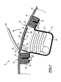
- the dashboard 2 of a motor vehicle 4 is covered, on the passenger side (right on the Figure 1 ), by a set 6 of interior lining extending between a door 8 of the glove box and the base of the windshield 12.
- the assembly 6 comprises a support frame 14, a lining panel 16 fixed to the frame 14, and a housing 18 defining a housing 20 for receiving a folded airbag 22.
- the airbag 22 is designed to be inflated rapidly in the event of an impact on the vehicle, for example by means of a gas generator triggered by a control unit associated with an impact sensor, such as an accelerometer.
- the armature 14 has the shape of an annular frame and defines a passage 24 for the airbag 22 during its deployment.
- the panel 16 covers the armature 14 and constitutes the visible part of the assembly 6.
- the panel 16 comprises a closed-contour breaking line 26 delimiting a flap 28 and a peripheral region 30 surrounding the flap 28.
- the armature 14 is fixed against the inner surface of the panel 16, ie the non-visible surface facing the inside of the assembly 6, for example by vibration welding, as will be described in more detail below.
- the breaking line 26 of the panel 16 is for example a line of lesser thickness of the panel 16 obtained by providing a groove 32 on the inner surface of the panel 16.
- the rupture line 26 substantially follows the contour of the passage 24.
- the flap 28 is located opposite the passage 24.
- the rupture line 26 is intended to break in the event of force applied on the inner surface of the flap 28 to allow the displacement of the flap 28 relative to the remainder of the panel 16, and thus to free the passage 24 to allow the airbag 22 to deploy to the outside.
- the assembly 6 comprises a band 34 forming a hinge connecting the flap 28 to the frame 14, and for retaining the flap 28 during its displacement.
- the band 34 comprises a flap portion 36 fixed to the flap 28, a frame portion 40 fixed to the frame 14, and a hinge portion 42 extending between the flap portion 36 and the frame portion 40
- the reinforcing portion 40 extends along a hinge edge 38 of the flap 28.
- the band 34 is in the form of a strip of flexible or flexible material, such as a textile material.
- the band 34 is preferably a mesh band or a net.
- the flexible band 34 allows the flap 28 to pivot relative to the panel 16 towards the outside by deformation of the hinge portion 42.
- the flap 28 pivots around its hinge edge 38, as illustrated in phantom on the Figure 2 .
- the band 34 is overmolded by reinforcing elements 44, 46 for reinforcement and attachment to the frame 14 and the flap 28 respectively.
- the assembly 6 comprises a first reinforcing element 44 overmolded on the flap portion 36 of the strip 34.
- This reinforcing element 44 is itself fixed on the flap 28, for example by welding the reinforcing element 44 against the inner surface of the flap 28, in particular by vibration welding, as will be described in more detail below.
- the assembly 6 comprises a second reinforcing element 46 overmolded on the reinforcing portion 40.
- This reinforcing element 46 is itself fixed on the armature 14 on the side opposite the panel 16, for example by screwing or spot welding as will be described in more detail below.
- the second reinforcing element 46 has the shape of a substantially rectangular plate wider than the band 34.
- the second reinforcing element 46 has lateral wings 48 extending laterally beyond the band 34.
- the assembly comprises a protective element 50 overmolded on the hinge portion 42 and covering only partially.
- the protective element 50 covers the region 52 of the hinge portion 42 adjacent to the armature portion 14.
- the region 54 of the hinge portion 42 adjacent the flap portion 36 is uncovered.
- the exposed region 54 extends between the covered region 52 and the flap portion 36.
- the covered region 52 extends over most of the length of the hinge portion 42 between the frame portion 40 and the flap portion. 36.
- the protective element 50 is integral with the second reinforcing element 46.
- the protection element 50 is in the form of a lip projecting from an edge of the second reinforcing element 46. by making an angle with the free state.
- the angle of inclination between the reinforcing element 46 and the protection element 50 is preferably between 0 ° and 90 °.
- the protective element 50 and the covered region 52 extend substantially rectilinearly from the reinforcing portion 40 and the reinforcing element 46 towards the edge 38 of the flap 28.
- the exposed region 54 connects the covered region 52 and the flap portion 36 by being folded due to the relative inclination between the covered region 52 and the flap portion 36.
- reinforcing portion 40 and the second reinforcing element 46 are fixed on the face of the armature 14 opposite the panel 16, on the edge 38 of the flap 28 side.
- the second reinforcing element 46 is screwed or welded by vibrations to the frame 14.
- the housing 18 comprises an opening 56 through which the housing 20 opens into the passage 24.
- the opening 56 has substantially the same section as the passage 24.
- the housing 18 comprises a peripheral rim 58 surrounding the opening 54, and by which the housing 18 is fixed on the frame 14, using screws or hooks.
- the reinforcing portion 40 and the second reinforcing element 46 are clamped between the flange 58 and the frame 14. They are traversed by flange 58 fixing screws on the frame 14. The screws passes through the reinforcing element 46 at right of band 34 and through wings 48.
- the airbag 22 is initially folded inside the housing 20. In the event of detection of a shock sustained by the motor vehicle, the airbag 22 is inflated and unfolds through the passage 24 by pushing the flap 28.
- the break line 26 breaks, allowing the flap 28 to move to release the passage 24 and allow the airbag 22 to expand outward to protect an occupant.
- the protective element 50 overmolded on the hinge portion 42 protects the latter when the airbag 22 hits it under the effect of its sudden swelling and limits the peak force passing through the band 34 in the region 54 discovered. This limits the risk of tearing of the band 34 and projection of the flap 28 in the passenger compartment.
- the protection element 50 has a certain rigidity, and because of its inclination towards the flap 28 and the center of the passage 24, it makes it possible to deflect the airbag 22 during its deployment towards the edge of the flap 28 opposite to the edge 38 hinge.
- the rupture line 26 begins to tear on the side of the flap 28 opposite to the hinge edge 38. This prevents the band 34 from being stressed too much and limits the risk of rupture of the band 34. rotation of the flap 28 around its hinge edge 38, and limits the risk of rupture between the flap portion 36 and the flap 28 of the panel 16.
- the protection element 50 covering only partially the hinge portion 42, and leaving a region 54 uncovered, facilitates the manufacture of the assembly 6, and ensures a better fixation of the band 34 on the flap 28.
- a method of manufacturing the assembly 6 comprises a first overmolding step of the band 34 by the reinforcing elements 44, 46 and the protection element 50.
- the tool 63 is provided with a cavity C for receiving the reinforcing element 46 and the protection element 50 in the folded position ( Figure 4 ).
- the reinforcing portion 40 and the reinforcing element 46 will be fixed on the armature 16, during the fixing of the housing 18 ( figure 2 ) on the armature 14.
- the reinforcing element 46 is vibratedly welded to the armature 14 before the housing 18 is fixed to the armature 14.
- the vibrations cause heating and welding of the reinforcing element 44 and the armature 14 against respectively the flap 28 and the panel 16.
- the discovery region 54 makes it possible to fold the band 34 with a small radius of curvature, in the limited residual space between the tool M, the panel 16 and the armature 14, to fold the band 34, the reinforcing element 44 and the protection element 50 in a configuration of minimum space allowing the passage of the tool 63, so as to weld the reinforcing element 44 on a large surface of the flap 28. This improves the connection between the strip 34 and the flap 28 and reduces the risk of ejection of the flap 28.
- the region 54 discovered is more flexible than the region 52 covered. It can be easily folded with a small length and a small radius of curvature.
- this makes it possible to make up the angle between the covered region 52 and the flap portion 36 over a short length of strip 34.
- a protective element 50 with a large area. extending to the vicinity of the flap portion 36 over the majority of the length of the hinge portion 42.
- the hinge portion 42 is thus effectively protected, and allows the pivoting of the flap 28 during deployment of the airbag 22, thanks to its region 54 flexible discovery.
- the embodiment of the figures 5 and 6 differs from that of figures 2 and 3 , whose reference numerals are repeated, in that the assembly 6 further comprises a deflector 64 integrally formed with the second reinforcing element 46 and the protection element 50.
- the deflector 64 extends the second reinforcing element 46 towards the center of the passage 24, so as to partially obstruct the passage 24 upstream of the band 34 in the direction of movement of the airbag 22 through the passage 24 during its deployment. on the side of the hinge edge 38 of the flap 28.
- the second reinforcing element 46 comprises two lateral extensions 66 ( figure 6 ) extending on each side of the deflector 64 being separated therefrom by rupture zones 68, defined for example by thinner areas obtained by forming grooves.
- the rupture zones 68 extend from the free edge 69 of the deflector 64, substantially perpendicular to it.
- the deflector 64 and the second reinforcing element 46 are connected by a film hinge 72 extending parallel to the free edge 69 of the deflector 64.
- the film hinge 72 is provided in the form of a thinner part obtained by forming a groove 73.
- the lateral extensions 66 are fixed on the armature 14, being for example welded and / or aimed at the armature 14.
- the deflector 64 protrudes across the passage 24 away from the guard member 50 and the band 34.
- the guard member 50 makes an angle of about 45 ° with the deflector 64.
- the deflector 64 deflects the airbag 22 towards the edge of the flap 28 opposite its hinge edge 38 in an improved manner with respect to the previous embodiment, and preserving the protective element 50 of the airbag 22. 'a direct impact with the airbag 22.
- the rupture zones 68 of the reinforcing element 44 break and the deflector 64 is folded against the protection element 50 by pivoting around the film hinge 72.
- the deflector 64 initially obstructs the passage 24 to deflect the airbag 22, then folds to better free the passage 24 and allow a better and faster deployment of the airbag 22.
- the lateral extensions 66 make it possible to retain the deflector 64 in the initial phase of deployment of the airbag 22 to ensure effective deflection thereof.
- the protection element 50 protects the hinge portion 42 from impact with the deflector 64, and indirectly with the airbag 22.
- the deflector 64 is obtained simply and at low cost by producing the reinforcing element 46, the protection element 50 and the deflector 64 in one piece of material obtained by overmolding plastic material on the strip 34.
- the deflector 64 has been shown with significant length for the sake of clarity of the drawings. In practice, the deflector 64 has a shorter length, sufficient to deflect the airbag 22 while allowing the insertion of the assembly formed by the reinforcing element 46, the protection element 50 and the deflector 64 in the cavity C of a tool 63 ( Figure 4 ) for the purpose of welding the reinforcing element 44 of the flap portion 36 over a large surface of the flap 28.
- protection provided by the deflector 64 is sufficient to ensure the integrity of the band 34, and in particular of the hinge portion 42, during the deployment of the airbag 22, it is possible to provide a set without any elements. protection 50. However, this is not covered by the claims.
- the invention applies to cladding assemblies for a motor vehicle dashboard, and also to interior door panels, and more generally to cladding assemblies of any element of a motor vehicle.
Landscapes
- Engineering & Computer Science (AREA)
- Mechanical Engineering (AREA)
- Air Bags (AREA)
Claims (15)
- Innenverkleidungsanordnung für Kraftfahrzeuge, umfassend ein Verstärkungsteil (14) und eine Platte (16) zum Abdecken eines Airbags, wobei die Platte (16) an dem Verstärkungsteil (14) befestigt ist und eine Klappe (28), die einen von dem Verstärkungsteil (14) begrenzten Durchgang (24) zum Entfalten des Airbags bedeckt, und einen Umfangsbereich (30) umfasst, der die Klappe (28) umgibt und an dem Verstärkungsteil (14) befestigt ist, wobei die Klappe (28) vorgesehen ist, sich bei dem Entfalten des Airbags zu bewegen, um den Durchgang (24) freizugeben, wobei die Platte (16) ein ein Scharnier bildendes Band (34) umfasst, das einen Klappenbereich (36), der an der Klappe (28) befestigt ist, einen Verstärkungsbereich (40), der an dem Verstärkungsteil (14) befestigt ist, und einen Scharnierbereich (42) besitzt, der sich zwischen dem Klappenbereich (36) und dem Verstärkungsteilbereich (40) erstreckt, dadurch gekennzeichnet, dass
das Gebiet des Scharnierbereichs (42) angrenzend an den Verstärkungsteilbereich (40) von einem Schutzelement (50) bedeckt ist, das auf dem Scharnierbereich (42) aufgeformt ist, um ihn zu schützen, wenn der Airbag durch die Wirkung seines Aufblasens ihn durchstößt, und dass das Gebiet des Scharnierbereichs (42) angrenzend an den Klappenbereich (48) aufgedeckt ist. - Anordnung nach Anspruch 1, bei der das bedeckte Gebiet den größten Teil der Länge des Scharnierteils (42) zwischen dem Klappenbereich (36) und dem Verstärkungsteilbereich (40) darstellt.
- Anordnung nach Anspruch 1 oder Anspruch 2, die ein Verstärkungselement (44) umfasst, das auf den Kappenbereich (36) ausgeformt ist.
- Anordnung nach Anspruch 3, bei der der Klappenbereich (36) an der Klappe (28) durch Schweißung des Verstärkungselements (44) befestigt ist, das den Klappenbereich (36) abdeckt.
- Anordnung nach einem beliebigen der vorhergehenden Ansprüche, die ein Verstärkungselement (46) umfasst, das auf den Verstärkungsteilbereich (40) aufgeformt ist.
- Anordnung nach Anspruch 5, bei der das Schutzelement (50) auf den Scharnierbereich (42) aufgeformt ist, indem aus einem Teil mit dem Verstärkungselement (46), das den Verstärkungsteilbereich abdeckt, hergestellt ist.
- Anordnung nach Anspruch 5 oder Anspruch 6, bei der das Schutzelement (50) mit dem Verstärkungselement (46) einen Winkel von 0° bis 90° einschließt.
- Anordnung nach Anspruch 6 oder Anspruch 7, bei der das Verstärkungselement (46), das den Verstärkungsteilbereich (40) abdeckt, die allgemeine Form einer Platte aufweist und das Schutzelement die Form einer Lippe (50) aufweist, die von einem Rand des Verstärkungselements (46), das den Verstärkungsteilbereich (40) abdeckt, hervorragt, wobei die Lippe (50) einen Winkel mit dem den Verstärkungsteilbereich abdeckenden Verstärkungselement (46) einnimmt.
- Anordnung (40) nach einem beliebigen der Ansprüche 5 bis 8, einen Ablenker (64) umfassend, der dazu angeordnet ist, teilweise einen Durchgang (24) vorgelagert zum Band (34) in Richtung der Entfaltung des Airbags zu versperren, wobei der Ablenker (64) aus einem Teil mit dem den Verstärkungsteilbereich (40) abdeckenden Verstärkungselement (46) hergestellt ist.
- Anordnung nach Anspruch 9, bei der der Ablenker (64) dazu vorgesehen ist, sich gegen den Zwischenbereich (42) des Bandes (34) umzuklappen.
- Anordnung nach Anspruch 10, bei der der Ablenker (64) ein Mittelstück (66), das sich quer durch den Durchgang (24) erstreckt, und zwei Seitenverlängerungen (67) umfasst, die an dem Verstärkungsteil (14) befestigt sind und von dem Mittelstück (66) durch mindestens eine Bruchlinie (68) getrennt sind, die vorgesehen ist zu brechen, damit das Mittelstück (66) sich gegen den Zwischenbereich (42) umklappen kann.
- Anordnung nach einem beliebigen der vorhergehenden Ansprüche, bei der das Band (34) ein vermaschtes Band oder ein Netz ist.
- Anordnung nach einem beliebigen der vorhergehenden Ansprüche, bei der die Platte (16) eine die Klappe (28) begrenzende Bruchlinie (26) aufweist, die vorgesehen ist zu brechen, um die Bewegung der Klappe (28) in Bezug auf die Umfangszone (30) für die Freisetzung des Durchgangs zu gestatten.
- Anordnung nach einem beliebigen der vorhergehenden Ansprüche, die ein Gehäuse (18) für die Aufnahme des gefalteten Airbags aufweist, wobei das Gehäuse (18) an dem Verstärkungsteil (14) entgegengesetzt zur Platte (16) befestigt ist und das Gehäuse eine Öffnung (60) besitzt, die in den Durchgang (24) mündet, wobei das Band (34) zwischen dem Verstärkungsteil (14) und einem Umfangsrand (62) des Gehäuses (18) eingeklemmt ist.
- Kraftfahrzeug, umfassend eine Anordnung nach einem der vorhergehenden Ansprüche.
Applications Claiming Priority (1)
| Application Number | Priority Date | Filing Date | Title |
|---|---|---|---|
| PCT/FR2008/051784 WO2010037915A1 (fr) | 2008-10-02 | 2008-10-02 | Ensemble d'habillage intérieur pour véhicule automobile et véhicule automobile |
Publications (2)
| Publication Number | Publication Date |
|---|---|
| EP2334520A1 EP2334520A1 (de) | 2011-06-22 |
| EP2334520B1 true EP2334520B1 (de) | 2014-01-15 |
Family
ID=40718567
Family Applications (1)
| Application Number | Title | Priority Date | Filing Date |
|---|---|---|---|
| EP08875647.3A Active EP2334520B1 (de) | 2008-10-02 | 2008-10-02 | Innenbekleidungseinheit für kraftfahrzeug und kraftfahrzeug |
Country Status (5)
| Country | Link |
|---|---|
| US (1) | US8424905B2 (de) |
| EP (1) | EP2334520B1 (de) |
| CN (1) | CN102216124B (de) |
| ES (1) | ES2451466T3 (de) |
| WO (1) | WO2010037915A1 (de) |
Families Citing this family (32)
| Publication number | Priority date | Publication date | Assignee | Title |
|---|---|---|---|---|
| DE102007055016B3 (de) * | 2007-11-14 | 2008-11-27 | Faurecia Innenraum Systeme Gmbh | Verkleidungsteil mit Airbagabdeckung und Verfahren zum Herstellen eines Verkleidungsteils |
| FR2941194B1 (fr) * | 2009-01-21 | 2011-02-18 | Faurecia Interieur Ind | Agencement de volet de coussin de securite gonflable articule sur une planche de bord |
| FR2941195B1 (fr) * | 2009-01-21 | 2012-10-05 | Faurecia Interieur Ind | Agencement de charniere de volet de coussin de securite gonflable articule sur une planche de bord |
| FR2962958B1 (fr) * | 2010-07-26 | 2012-08-10 | Faurecia Interieur Ind | Agencement de coussin de securite gonflable comportant un volet relie a une planche de bord par un lien lineaire a quatre portions de retenue paralleles |
| WO2012051738A1 (en) * | 2010-10-21 | 2012-04-26 | Faurecia Interieur Industrie | Trim panel for automotive vehicle comprising door hinged on the trim panel by flexible hinge member |
| WO2013029240A1 (en) * | 2011-08-30 | 2013-03-07 | Faurecia (Shanghai) Management Company, Ltd | Trim assembly for covering airbag |
| FR2979600B1 (fr) * | 2011-09-01 | 2013-09-27 | Faurecia Interieur Ind | Dispositif de securite pour vehicule |
| DE102012107234B3 (de) * | 2012-08-07 | 2014-01-16 | Visteon Global Technologies, Inc. | Innenverkleidungsteil mit einer Airbagklappe für ein Kraftfahrzeug |
| EP2749458B1 (de) | 2012-12-28 | 2015-04-15 | Faurecia Innenraum Systeme GmbH | Verkleidungsteil mit Airbagabdeckung und Verfahren zur Herstellung eines Verkleidungsteils |
| CN105324277B (zh) * | 2013-05-31 | 2017-05-31 | 奥托立夫开发公司 | 安全气囊装置 |
| FR3007348B1 (fr) | 2013-06-24 | 2017-12-22 | Faurecia Interieur Ind | Dispositif de securite pour vehicule |
| FR3007350B1 (fr) * | 2013-06-24 | 2015-06-05 | Faurecia Interieur Ind | Dispositif de securite pour vehicule. |
| DE102013011971A1 (de) * | 2013-07-18 | 2015-01-22 | GM Global Technology Operations LLC (n. d. Gesetzen des Staates Delaware) | Airbaganordnung für ein Fahrzeug |
| FR3024691B1 (fr) * | 2014-08-08 | 2016-08-26 | Faurecia Interieur Ind | Systeme de securite a coussin gonflable pour vehicule renforce par un filet incise |
| EP3034361B1 (de) * | 2014-12-16 | 2018-04-18 | Volvo Car Corporation | Airbagabdeckung und Herstellungsverfahren für eine Airbagabdeckung |
| DE102015001234A1 (de) * | 2015-02-03 | 2016-08-04 | Dalphi Metal Espana, S.A. | Verfahren zum umhüllen eines aufblasbaren gassacks zum schutz einer person, umhüllter aufblasbarer gassack, umhüllung fur einen aufblasbaren gassack, gassackmodul und fahrzeugsicherheitssystem |
| JP6451551B2 (ja) * | 2015-08-21 | 2019-01-16 | 豊田合成株式会社 | 自動車用エアバッグドア |
| CN105365739A (zh) * | 2015-11-25 | 2016-03-02 | 江苏新泉汽车饰件股份有限公司 | 搪塑发泡型汽车仪表板气囊安装部件 |
| KR101776465B1 (ko) * | 2016-03-14 | 2017-09-08 | 현대자동차주식회사 | 일체형 크래쉬패드 및 그 제조방법 |
| JP6546887B2 (ja) * | 2016-09-05 | 2019-07-17 | 豊田合成株式会社 | エアバッグカバー |
| DE102016217659A1 (de) * | 2016-09-15 | 2018-03-15 | Volkswagen Aktiengesellschaft | Airbaganordnung in einem Fahrzeug |
| EP3360733B1 (de) * | 2017-02-09 | 2019-10-09 | Autoliv Development AB | Airbagmodul mit einem behälter und einer flexiblen abdeckung |
| US10220807B2 (en) | 2017-03-22 | 2019-03-05 | Ford Global Technologies, Llc | Restricted-opening door hinge for automotive air bag chute |
| DE102017208230A1 (de) * | 2017-05-16 | 2018-11-22 | Audi Ag | Befestigen eines Airbags im Fahrzeug |
| DE202017105555U1 (de) * | 2017-09-14 | 2018-12-17 | Dalphi Metal Espana, S.A. | Aufblasschutz zum Verhindern von Beschädigungen beim Aufblasen eines Gassackes |
| EP3560772B1 (de) * | 2018-04-26 | 2021-02-24 | Faurecia Interieur Industrie | Airbagsystem für ein fahrzeug und verfahren zur herstellung des airbagsystems |
| KR102495608B1 (ko) * | 2018-05-14 | 2023-02-03 | 현대모비스 주식회사 | 동승석 에어백 장치 |
| DE102018222480B4 (de) * | 2018-12-20 | 2020-07-02 | Psa Automobiles Sa | Kraftfahrzeughaube mit Airbaganordnung |
| JP2022527954A (ja) * | 2019-03-29 | 2022-06-07 | Mcppイノベーション合同会社 | 全tpoエアバッグ組み立て体 |
| US11247632B2 (en) | 2019-10-07 | 2022-02-15 | Ford Global Technologies, Llc | Airbag assembly with releasable panel |
| JP7041314B1 (ja) * | 2021-08-16 | 2022-03-23 | マレリ株式会社 | エアバッグ取付構造 |
| JP7218079B1 (ja) * | 2022-03-09 | 2023-02-06 | マレリ株式会社 | エアバッグ取付構造 |
Family Cites Families (37)
| Publication number | Priority date | Publication date | Assignee | Title |
|---|---|---|---|---|
| DE4315853C2 (de) * | 1993-05-12 | 1996-05-15 | Ymos Ag Ind Produkte | Armaturentafel mit Beifahrer-Airbag |
| JPH0794008A (ja) | 1993-09-24 | 1995-04-07 | Chiyatani Sangyo Kk | 面照明装置 |
| JPH07285406A (ja) | 1994-04-21 | 1995-10-31 | Toyoda Gosei Co Ltd | 助手席用エアバッグ装置 |
| EP0813026A3 (de) | 1996-06-14 | 1999-12-22 | BARTENBACH Christian | Beleuchtungseinrichtung |
| AU7699598A (en) * | 1997-06-09 | 1998-12-30 | Textron Automotive Company Inc. | Apparatus for deploying an airbag through a hard panel |
| JPH11237629A (ja) | 1998-02-20 | 1999-08-31 | Stanley Electric Co Ltd | 照明用面光源装置 |
| US6893135B2 (en) | 2000-03-16 | 2005-05-17 | 3M Innovative Properties Company | Light guides suitable for illuminated displays |
| AU2002217573A1 (en) * | 2000-12-13 | 2002-06-24 | Hyundai Mobis, Co. | Passenger restraining apparatus for vehicle |
| DE10123263B4 (de) | 2001-05-12 | 2005-12-08 | Daimlerchrysler Ag | Lichtleitsystem für den Innenraum eines Kraftfahrzeugs |
| DE10129953A1 (de) | 2001-06-21 | 2003-01-16 | Hella Kg Hueck & Co | Leuchte für Fahrzeuginnenräume |
| US6644685B2 (en) * | 2001-09-07 | 2003-11-11 | Visteon Global Technologies, Inc. | Seamless passenger side airbag door |
| US6663262B2 (en) | 2001-09-10 | 2003-12-16 | 3M Innovative Properties Company | Backlighting transmissive displays |
| US7250951B1 (en) * | 2002-04-10 | 2007-07-31 | Peter Hurley | System and method for visualizing data |
| DE60304165T2 (de) | 2002-05-21 | 2006-11-09 | Koninklijke Philips Electronics N.V. | Anzeigevorrichtung mit lichtleitplatte |
| US20040119267A1 (en) * | 2002-12-19 | 2004-06-24 | Lear Corporation | Natural fiber tether for an airbag system |
| US7140636B2 (en) * | 2003-05-07 | 2006-11-28 | Lear Corporation | Airbag support assembly for a vehicle instrument panel |
| WO2004111532A1 (ja) | 2003-06-16 | 2004-12-23 | Advanced Display Inc. | 面状光源装置および該装置を用いた表示装置 |
| KR100580466B1 (ko) * | 2003-11-27 | 2006-05-15 | 현대자동차주식회사 | 슬라이딩 힌지를 적용한 이음매가 없는 승객용 에어백의전개 구조 |
| US7160404B2 (en) * | 2003-12-10 | 2007-01-09 | Lear Corporation | Method of manufacturing an airbag assembly and vehicle trim component |
| DE10361581A1 (de) | 2003-12-23 | 2005-07-21 | Volkswagen Ag | Verkleidungsteil zum Abdecken einer Austrittsöffnung einer Insassenschutzeinrichtung und ein Verfahren zum Herstellen einer Aufreißlinie an einem Verkleidungsteil |
| US20050280524A1 (en) | 2004-06-18 | 2005-12-22 | Applied Digital, Inc. | Vehicle entertainment and accessory control system |
| JP4444032B2 (ja) | 2004-08-06 | 2010-03-31 | 三菱電機株式会社 | 車室内照明装置 |
| FR2877896A1 (fr) | 2004-11-16 | 2006-05-19 | Cera | Element de garnissage de vehicule automobile comprenant un medaillon retroeclaire |
| DE602006008938D1 (de) | 2005-05-31 | 2009-10-15 | Koninkl Philips Electronics Nv | Lichtquelle mit stoff-diffusionsschicht |
| KR100638874B1 (ko) | 2005-07-06 | 2006-10-27 | 삼성전기주식회사 | Led 광원이 도광판에 삽입된 백라이트 장치의광원-도광판 구조 및 이를 포함하는 백라이트 장치 |
| JP2007062701A (ja) * | 2005-09-02 | 2007-03-15 | Takata Corp | エアバッグ装置及びその蓋部材 |
| US7284886B2 (en) | 2005-11-23 | 2007-10-23 | Volkswagen Ag | Moonroof for a motor vehicle |
| DE102006017960A1 (de) | 2006-04-13 | 2007-10-25 | Hella Kgaa Hueck & Co. | Inneneinrichtung für ein Kraftfahrzeug |
| US7370995B2 (en) | 2006-05-04 | 2008-05-13 | International Automotive Components Group North America, Inc. | Console and light assembly |
| FR2902727B1 (fr) * | 2006-06-21 | 2009-04-17 | Faurecia Interieur Ind Snc | Planche de bord a portillon monte sur charniere souple |
| WO2008016160A1 (fr) | 2006-07-31 | 2008-02-07 | Toyota Shatai Kabushiki Kaisha | Porte d'airbag, procédé de contrôle de rupture de ligne de rupture, et procédé de gonflement d'airbag |
| TWI354164B (en) | 2006-10-03 | 2011-12-11 | Au Optronics Corp | Liquid crystal display and back light module there |
| DE102007055016B3 (de) * | 2007-11-14 | 2008-11-27 | Faurecia Innenraum Systeme Gmbh | Verkleidungsteil mit Airbagabdeckung und Verfahren zum Herstellen eines Verkleidungsteils |
| FR2925410B1 (fr) * | 2007-12-21 | 2010-05-14 | Faurecia Interieur Ind | Planche de bord amelioree |
| US8408588B2 (en) * | 2008-03-19 | 2013-04-02 | Johnson Controls Technology Company | Fixture having airbag outlet flap |
| FR2929569B1 (fr) * | 2008-04-03 | 2010-09-17 | Faurecia Interieur Ind | Dispositif de fixation d'un volet de coussin gonflable |
| KR101240603B1 (ko) * | 2010-11-22 | 2013-03-06 | 현대모비스 주식회사 | 조수석 에어백 도어 |
-
2008
- 2008-10-02 CN CN200880132005.2A patent/CN102216124B/zh active Active
- 2008-10-02 EP EP08875647.3A patent/EP2334520B1/de active Active
- 2008-10-02 WO PCT/FR2008/051784 patent/WO2010037915A1/fr active Application Filing
- 2008-10-02 US US13/122,551 patent/US8424905B2/en active Active
- 2008-10-02 ES ES08875647.3T patent/ES2451466T3/es active Active
Also Published As
| Publication number | Publication date |
|---|---|
| US20110181028A1 (en) | 2011-07-28 |
| EP2334520A1 (de) | 2011-06-22 |
| WO2010037915A1 (fr) | 2010-04-08 |
| ES2451466T3 (es) | 2014-03-27 |
| CN102216124B (zh) | 2014-06-25 |
| CN102216124A (zh) | 2011-10-12 |
| US8424905B2 (en) | 2013-04-23 |
Similar Documents
| Publication | Publication Date | Title |
|---|---|---|
| EP2334520B1 (de) | Innenbekleidungseinheit für kraftfahrzeug und kraftfahrzeug | |
| EP1199228B1 (de) | Kraftfahrzeugairbagabdeckung und das dazugehörige Herstellungsverfahren | |
| EP1514768B1 (de) | Gebrauchsverfahren fur einem Kotflügel und eine Motorhaube, mit einem Luftkissen und einem Kotflügel Stutz , Kfz-Kotflügel, Kfz-Kotflügelmodul, und Kfz-Motorhaube | |
| EP2550185B1 (de) | Aufblasbare airbaganordnung auf einem armaturenbrett mit einer über eine lineare verbindung mit dem armaturenbrett verbundenen klappe | |
| WO2010084123A1 (fr) | Agencement de volet de coussin de sécurité gonflable articulé sur une planche de bord | |
| EP2219906B1 (de) | Armaturenbrett mit einem airbag | |
| EP1354773B1 (de) | Verfahren zur Herstellung eines Instrumententafelteils ausgerüstet mit einem Airbag | |
| EP2379373A1 (de) | Scharnieranordnung für eine an einem armaturenbrett angebrachte airbagklappe | |
| EP0819587B1 (de) | Luftsackmodul-Anordnung in einem Fahrzeugsitz | |
| EP0953484B1 (de) | Seitenairbagmodul- Montagevorrichtung für einen Vordersitz eines Kraftfahrzeuges | |
| WO2004009410A1 (fr) | Ensemble de masquage d'un coussin gonflable de securite a organes de renfort et procede de realisation correspondants | |
| FR2927290A1 (fr) | Planche de bord amelioree comportant un volet muni d'une plaque de renfort en plastique rigide. | |
| FR2799700A1 (fr) | Planche de bord a rigidite amelioree, equipee d'un coussin de protection et ensemble adapte a un vehicule automobile | |
| EP2052919A1 (de) | Sicherheitsvorrichtung mit Airbag für Kraftfahrzeug | |
| FR2809692A1 (fr) | Ensemble de masquage d'un coussin gonflable de securite pour vehicule automobile, procede de fabrication et planche de bord correspondante | |
| EP1426250B1 (de) | Eine aus einer aufblasbaren Struktur und einem zerbrechbaren Befestigungsbauteil bestehende Ausrüstung und damit ausgerüstetes Fahrzeug | |
| FR2796610A1 (fr) | Piece d'equipement interieur pour vehicule, en particulier planche de bord | |
| FR2877296A1 (fr) | Element de siege de vehicule muni d'un coussin de securite et procede de fabrication | |
| EP2782795B1 (de) | Airbagvorrichtung mit einem deflektor und einem beutelstützenden flansch | |
| FR2863572A1 (fr) | Ensemble de planche de bord de vehicule automobile pour airbag invisible | |
| FR2905327A3 (fr) | Vehicule avec dispositif associant les protections a coussin gonflable et pare soleil | |
| FR2830815A1 (fr) | Siege de vehicule automobile comportant un dispositif de securite a sac gonflable lateral | |
| EP2910433B1 (de) | Dachhimmel angepasst für Airbag-Auslösung | |
| FR2947226A1 (fr) | Agencement pour coussin de securite gonflable equipant une planche de bord de vehicule automobile comprenant un volet articule | |
| FR3104510A1 (fr) | Boitier à coussin gonflable, dispositif de sécurité et procédé de fabrication d’un tel dispositif |
Legal Events
| Date | Code | Title | Description |
|---|---|---|---|
| PUAI | Public reference made under article 153(3) epc to a published international application that has entered the european phase |
Free format text: ORIGINAL CODE: 0009012 |
|
| 17P | Request for examination filed |
Effective date: 20110401 |
|
| AK | Designated contracting states |
Kind code of ref document: A1 Designated state(s): AT BE BG CH CY CZ DE DK EE ES FI FR GB GR HR HU IE IS IT LI LT LU LV MC MT NL NO PL PT RO SE SI SK TR |
|
| AX | Request for extension of the european patent |
Extension state: AL BA MK RS |
|
| DAX | Request for extension of the european patent (deleted) | ||
| RIN1 | Information on inventor provided before grant (corrected) |
Inventor name: BRUNET, MICHAEL |
|
| 17Q | First examination report despatched |
Effective date: 20120806 |
|
| GRAP | Despatch of communication of intention to grant a patent |
Free format text: ORIGINAL CODE: EPIDOSNIGR1 |
|
| INTG | Intention to grant announced |
Effective date: 20130808 |
|
| GRAS | Grant fee paid |
Free format text: ORIGINAL CODE: EPIDOSNIGR3 |
|
| GRAA | (expected) grant |
Free format text: ORIGINAL CODE: 0009210 |
|
| AK | Designated contracting states |
Kind code of ref document: B1 Designated state(s): AT BE BG CH CY CZ DE DK EE ES FI FR GB GR HR HU IE IS IT LI LT LU LV MC MT NL NO PL PT RO SE SI SK TR |
|
| REG | Reference to a national code |
Ref country code: CH Ref legal event code: EP Ref country code: GB Ref legal event code: FG4D Free format text: NOT ENGLISH |
|
| REG | Reference to a national code |
Ref country code: AT Ref legal event code: REF Ref document number: 649674 Country of ref document: AT Kind code of ref document: T Effective date: 20140215 |
|
| REG | Reference to a national code |
Ref country code: IE Ref legal event code: FG4D Free format text: LANGUAGE OF EP DOCUMENT: FRENCH |
|
| REG | Reference to a national code |
Ref country code: DE Ref legal event code: R096 Ref document number: 602008030010 Country of ref document: DE Effective date: 20140227 |
|
| REG | Reference to a national code |
Ref country code: ES Ref legal event code: FG2A Ref document number: 2451466 Country of ref document: ES Kind code of ref document: T3 Effective date: 20140327 |
|
| REG | Reference to a national code |
Ref country code: NL Ref legal event code: VDEP Effective date: 20140115 |
|
| REG | Reference to a national code |
Ref country code: AT Ref legal event code: MK05 Ref document number: 649674 Country of ref document: AT Kind code of ref document: T Effective date: 20140115 |
|
| REG | Reference to a national code |
Ref country code: LT Ref legal event code: MG4D |
|
| REG | Reference to a national code |
Ref country code: SK Ref legal event code: T3 Ref document number: E 16151 Country of ref document: SK |
|
| PG25 | Lapsed in a contracting state [announced via postgrant information from national office to epo] |
Ref country code: IS Free format text: LAPSE BECAUSE OF FAILURE TO SUBMIT A TRANSLATION OF THE DESCRIPTION OR TO PAY THE FEE WITHIN THE PRESCRIBED TIME-LIMIT Effective date: 20140515 Ref country code: NO Free format text: LAPSE BECAUSE OF FAILURE TO SUBMIT A TRANSLATION OF THE DESCRIPTION OR TO PAY THE FEE WITHIN THE PRESCRIBED TIME-LIMIT Effective date: 20140415 Ref country code: LT Free format text: LAPSE BECAUSE OF FAILURE TO SUBMIT A TRANSLATION OF THE DESCRIPTION OR TO PAY THE FEE WITHIN THE PRESCRIBED TIME-LIMIT Effective date: 20140115 |
|
| PG25 | Lapsed in a contracting state [announced via postgrant information from national office to epo] |
Ref country code: CY Free format text: LAPSE BECAUSE OF FAILURE TO SUBMIT A TRANSLATION OF THE DESCRIPTION OR TO PAY THE FEE WITHIN THE PRESCRIBED TIME-LIMIT Effective date: 20140115 Ref country code: FI Free format text: LAPSE BECAUSE OF FAILURE TO SUBMIT A TRANSLATION OF THE DESCRIPTION OR TO PAY THE FEE WITHIN THE PRESCRIBED TIME-LIMIT Effective date: 20140115 Ref country code: AT Free format text: LAPSE BECAUSE OF FAILURE TO SUBMIT A TRANSLATION OF THE DESCRIPTION OR TO PAY THE FEE WITHIN THE PRESCRIBED TIME-LIMIT Effective date: 20140115 Ref country code: SE Free format text: LAPSE BECAUSE OF FAILURE TO SUBMIT A TRANSLATION OF THE DESCRIPTION OR TO PAY THE FEE WITHIN THE PRESCRIBED TIME-LIMIT Effective date: 20140115 Ref country code: NL Free format text: LAPSE BECAUSE OF FAILURE TO SUBMIT A TRANSLATION OF THE DESCRIPTION OR TO PAY THE FEE WITHIN THE PRESCRIBED TIME-LIMIT Effective date: 20140115 Ref country code: PT Free format text: LAPSE BECAUSE OF FAILURE TO SUBMIT A TRANSLATION OF THE DESCRIPTION OR TO PAY THE FEE WITHIN THE PRESCRIBED TIME-LIMIT Effective date: 20140515 |
|
| PG25 | Lapsed in a contracting state [announced via postgrant information from national office to epo] |
Ref country code: HR Free format text: LAPSE BECAUSE OF FAILURE TO SUBMIT A TRANSLATION OF THE DESCRIPTION OR TO PAY THE FEE WITHIN THE PRESCRIBED TIME-LIMIT Effective date: 20140115 Ref country code: LV Free format text: LAPSE BECAUSE OF FAILURE TO SUBMIT A TRANSLATION OF THE DESCRIPTION OR TO PAY THE FEE WITHIN THE PRESCRIBED TIME-LIMIT Effective date: 20140115 |
|
| REG | Reference to a national code |
Ref country code: DE Ref legal event code: R097 Ref document number: 602008030010 Country of ref document: DE |
|
| PG25 | Lapsed in a contracting state [announced via postgrant information from national office to epo] |
Ref country code: RO Free format text: LAPSE BECAUSE OF FAILURE TO SUBMIT A TRANSLATION OF THE DESCRIPTION OR TO PAY THE FEE WITHIN THE PRESCRIBED TIME-LIMIT Effective date: 20140115 Ref country code: EE Free format text: LAPSE BECAUSE OF FAILURE TO SUBMIT A TRANSLATION OF THE DESCRIPTION OR TO PAY THE FEE WITHIN THE PRESCRIBED TIME-LIMIT Effective date: 20140115 Ref country code: CZ Free format text: LAPSE BECAUSE OF FAILURE TO SUBMIT A TRANSLATION OF THE DESCRIPTION OR TO PAY THE FEE WITHIN THE PRESCRIBED TIME-LIMIT Effective date: 20140115 Ref country code: DK Free format text: LAPSE BECAUSE OF FAILURE TO SUBMIT A TRANSLATION OF THE DESCRIPTION OR TO PAY THE FEE WITHIN THE PRESCRIBED TIME-LIMIT Effective date: 20140115 |
|
| PLBE | No opposition filed within time limit |
Free format text: ORIGINAL CODE: 0009261 |
|
| STAA | Information on the status of an ep patent application or granted ep patent |
Free format text: STATUS: NO OPPOSITION FILED WITHIN TIME LIMIT |
|
| PG25 | Lapsed in a contracting state [announced via postgrant information from national office to epo] |
Ref country code: PL Free format text: LAPSE BECAUSE OF FAILURE TO SUBMIT A TRANSLATION OF THE DESCRIPTION OR TO PAY THE FEE WITHIN THE PRESCRIBED TIME-LIMIT Effective date: 20140115 |
|
| 26N | No opposition filed |
Effective date: 20141016 |
|
| REG | Reference to a national code |
Ref country code: DE Ref legal event code: R097 Ref document number: 602008030010 Country of ref document: DE Effective date: 20141016 |
|
| PG25 | Lapsed in a contracting state [announced via postgrant information from national office to epo] |
Ref country code: SI Free format text: LAPSE BECAUSE OF FAILURE TO SUBMIT A TRANSLATION OF THE DESCRIPTION OR TO PAY THE FEE WITHIN THE PRESCRIBED TIME-LIMIT Effective date: 20140115 Ref country code: LU Free format text: LAPSE BECAUSE OF FAILURE TO SUBMIT A TRANSLATION OF THE DESCRIPTION OR TO PAY THE FEE WITHIN THE PRESCRIBED TIME-LIMIT Effective date: 20141002 Ref country code: MC Free format text: LAPSE BECAUSE OF FAILURE TO SUBMIT A TRANSLATION OF THE DESCRIPTION OR TO PAY THE FEE WITHIN THE PRESCRIBED TIME-LIMIT Effective date: 20140115 |
|
| REG | Reference to a national code |
Ref country code: CH Ref legal event code: PL |
|
| GBPC | Gb: european patent ceased through non-payment of renewal fee |
Effective date: 20141002 |
|
| PG25 | Lapsed in a contracting state [announced via postgrant information from national office to epo] |
Ref country code: BE Free format text: LAPSE BECAUSE OF NON-PAYMENT OF DUE FEES Effective date: 20141031 |
|
| REG | Reference to a national code |
Ref country code: IE Ref legal event code: MM4A |
|
| PG25 | Lapsed in a contracting state [announced via postgrant information from national office to epo] |
Ref country code: GB Free format text: LAPSE BECAUSE OF NON-PAYMENT OF DUE FEES Effective date: 20141002 Ref country code: LI Free format text: LAPSE BECAUSE OF NON-PAYMENT OF DUE FEES Effective date: 20141031 Ref country code: CH Free format text: LAPSE BECAUSE OF NON-PAYMENT OF DUE FEES Effective date: 20141031 |
|
| PG25 | Lapsed in a contracting state [announced via postgrant information from national office to epo] |
Ref country code: IE Free format text: LAPSE BECAUSE OF NON-PAYMENT OF DUE FEES Effective date: 20141002 |
|
| PG25 | Lapsed in a contracting state [announced via postgrant information from national office to epo] |
Ref country code: BG Free format text: LAPSE BECAUSE OF FAILURE TO SUBMIT A TRANSLATION OF THE DESCRIPTION OR TO PAY THE FEE WITHIN THE PRESCRIBED TIME-LIMIT Effective date: 20140115 |
|
| PG25 | Lapsed in a contracting state [announced via postgrant information from national office to epo] |
Ref country code: IT Free format text: LAPSE BECAUSE OF FAILURE TO SUBMIT A TRANSLATION OF THE DESCRIPTION OR TO PAY THE FEE WITHIN THE PRESCRIBED TIME-LIMIT Effective date: 20140115 Ref country code: GR Free format text: LAPSE BECAUSE OF FAILURE TO SUBMIT A TRANSLATION OF THE DESCRIPTION OR TO PAY THE FEE WITHIN THE PRESCRIBED TIME-LIMIT Effective date: 20140416 |
|
| PG25 | Lapsed in a contracting state [announced via postgrant information from national office to epo] |
Ref country code: HU Free format text: LAPSE BECAUSE OF FAILURE TO SUBMIT A TRANSLATION OF THE DESCRIPTION OR TO PAY THE FEE WITHIN THE PRESCRIBED TIME-LIMIT; INVALID AB INITIO Effective date: 20081002 Ref country code: MT Free format text: LAPSE BECAUSE OF FAILURE TO SUBMIT A TRANSLATION OF THE DESCRIPTION OR TO PAY THE FEE WITHIN THE PRESCRIBED TIME-LIMIT Effective date: 20140115 Ref country code: TR Free format text: LAPSE BECAUSE OF FAILURE TO SUBMIT A TRANSLATION OF THE DESCRIPTION OR TO PAY THE FEE WITHIN THE PRESCRIBED TIME-LIMIT Effective date: 20140115 |
|
| REG | Reference to a national code |
Ref country code: FR Ref legal event code: PLFP Year of fee payment: 9 |
|
| REG | Reference to a national code |
Ref country code: FR Ref legal event code: PLFP Year of fee payment: 10 |
|
| REG | Reference to a national code |
Ref country code: FR Ref legal event code: PLFP Year of fee payment: 11 |
|
| PGFP | Annual fee paid to national office [announced via postgrant information from national office to epo] |
Ref country code: SK Payment date: 20210928 Year of fee payment: 14 |
|
| PGFP | Annual fee paid to national office [announced via postgrant information from national office to epo] |
Ref country code: DE Payment date: 20210921 Year of fee payment: 14 |
|
| REG | Reference to a national code |
Ref country code: DE Ref legal event code: R119 Ref document number: 602008030010 Country of ref document: DE |
|
| REG | Reference to a national code |
Ref country code: SK Ref legal event code: MM4A Ref document number: E 16151 Country of ref document: SK Effective date: 20221002 |
|
| PG25 | Lapsed in a contracting state [announced via postgrant information from national office to epo] |
Ref country code: DE Free format text: LAPSE BECAUSE OF NON-PAYMENT OF DUE FEES Effective date: 20230503 |
|
| PG25 | Lapsed in a contracting state [announced via postgrant information from national office to epo] |
Ref country code: SK Free format text: LAPSE BECAUSE OF NON-PAYMENT OF DUE FEES Effective date: 20221002 |
|
| PGFP | Annual fee paid to national office [announced via postgrant information from national office to epo] |
Ref country code: FR Payment date: 20230920 Year of fee payment: 16 |
|
| PGFP | Annual fee paid to national office [announced via postgrant information from national office to epo] |
Ref country code: ES Payment date: 20231102 Year of fee payment: 16 |