EP1514768B1 - Gebrauchsverfahren fur einem Kotflügel und eine Motorhaube, mit einem Luftkissen und einem Kotflügel Stutz , Kfz-Kotflügel, Kfz-Kotflügelmodul, und Kfz-Motorhaube - Google Patents
Gebrauchsverfahren fur einem Kotflügel und eine Motorhaube, mit einem Luftkissen und einem Kotflügel Stutz , Kfz-Kotflügel, Kfz-Kotflügelmodul, und Kfz-Motorhaube Download PDFInfo
- Publication number
- EP1514768B1 EP1514768B1 EP04292156A EP04292156A EP1514768B1 EP 1514768 B1 EP1514768 B1 EP 1514768B1 EP 04292156 A EP04292156 A EP 04292156A EP 04292156 A EP04292156 A EP 04292156A EP 1514768 B1 EP1514768 B1 EP 1514768B1
- Authority
- EP
- European Patent Office
- Prior art keywords
- fender
- wing
- hood
- vehicle
- airbag
- Prior art date
- Legal status (The legal status is an assumption and is not a legal conclusion. Google has not performed a legal analysis and makes no representation as to the accuracy of the status listed.)
- Expired - Lifetime
Links
Images


Classifications
-
- B—PERFORMING OPERATIONS; TRANSPORTING
- B60—VEHICLES IN GENERAL
- B60R—VEHICLES, VEHICLE FITTINGS, OR VEHICLE PARTS, NOT OTHERWISE PROVIDED FOR
- B60R21/00—Arrangements or fittings on vehicles for protecting or preventing injuries to occupants or pedestrians in case of accidents or other traffic risks
- B60R21/34—Protecting non-occupants of a vehicle, e.g. pedestrians
- B60R21/36—Protecting non-occupants of a vehicle, e.g. pedestrians using airbags
-
- B—PERFORMING OPERATIONS; TRANSPORTING
- B62—LAND VEHICLES FOR TRAVELLING OTHERWISE THAN ON RAILS
- B62D—MOTOR VEHICLES; TRAILERS
- B62D25/00—Superstructure or monocoque structure sub-units; Parts or details thereof not otherwise provided for
- B62D25/08—Front or rear portions
- B62D25/10—Bonnets or lids, e.g. for trucks, tractors, busses, work vehicles
- B62D25/105—Bonnets or lids, e.g. for trucks, tractors, busses, work vehicles for motor cars
-
- B—PERFORMING OPERATIONS; TRANSPORTING
- B62—LAND VEHICLES FOR TRAVELLING OTHERWISE THAN ON RAILS
- B62D—MOTOR VEHICLES; TRAILERS
- B62D25/00—Superstructure or monocoque structure sub-units; Parts or details thereof not otherwise provided for
- B62D25/08—Front or rear portions
- B62D25/16—Mud-guards or wings; Wheel cover panels
Definitions
- the present invention relates to a use of a wing and a hood in combination with an airbag, a retaining means and a wing support, a wing, a wing module and a hood of a motor vehicle.
- junction wing / hood relatively stiff because of the juxtapositions of the edges of the hood and the wing.
- the present invention aims to provide protection wing-hood junction wide enough to support the entire head of the pedestrian, and also protect the pedestrian other rigid parts further from the junction, such as the battery or the damper cups .
- the subject of the invention is a use of a wing and a cowl at the front of a motor vehicle, providing a wing-cowl junction leaving a predetermined clearance between a rim of the cowl and an edge of the wing, in combination with an airbag intended to be deployed outside the vehicle, so that during its deployment, the airbag deforms the wing and / or the hood so as to enlarge the game and to create a passage between the edge of the hood and the edge of the wing.
- the airbag when the airbag deploys, it exerts a pressure on the wing or on the hood which, appropriately sized, easily deformed so as to enlarge the space between the wing and the bonnet for let the air bag out and protect a relatively large area.
- a particular advantage of the invention is to adapt to any type of vehicle, including a vehicle with too little space in the vicinity of the wing to implement a passive pedestrian protection system, such as a room absorption, while providing greater protection than this passive system.
- each cushion is dimensioned differently depending on whether it is intended to protect an adult or a child.
- the invention also relates to a means for retaining a front wing of a motor vehicle, maintained in normal position of use on the vehicle by a holding means, the holding means being separate from the retaining means and being adapted to release the wing when it undergoes a force greater than a predetermined threshold, said retaining means being characterized in that it is able to retain the wing released by the holding means.
- An advantage of this means of restraint is that it prevents that, during the deployment of the airbag, the wing or a portion of the wing is projected to the outside of the vehicle and may not hurt a potential pedestrian or falls dangerously in the middle of the road.
- the invention also relates to a front wing support of a motor vehicle, connecting an upper part of the wing to the vehicle structure, the wing having an edge intended to abut a hood leaving a predetermined clearance with an edge hood, characterized in that it comprises a pivot by which it can be connected to the structure, so as to allow the enlargement of the game.
- this wing support is electrically controlled.
- this wing support is used in combination with an airbag arranged to push on the support.
- the invention also relates to a front wing support of a motor vehicle, connecting an upper part of the wing to the vehicle structure, characterized in that it comprises a housing for an airbag located between the inside of the vehicle. wing and the structure of the vehicle.
- this wing support comprises, on the side of the structure, a sole serving as a bearing surface for the airbag during its deployment.
- this wing support comprises an area capable of breaking under the pressure of the airbag to release the upper part of the wing.
- the invention also relates to a front wing of a motor vehicle having a body skin separating the inside and the outside of the wing, terminated by an edge intended to abut a hood, characterized in that it comprises a housing for an airbag, located inside the wing and in the vicinity of the edge.
- This wing can be made of plastic or sheet metal.
- plastic wing is that it is possible to mold complex shapes and thus easily obtain a conformation compatible with the deployment of the airbag.
- the invention also relates to a front wing module of a motor vehicle, comprising a front wing and a wing support of the aforementioned type.
- the car manufacturers can integrate, in addition to the outfit and appearance, a safety function in the wing module, without changing the vehicle style.
- wing module Another advantage provided by this wing module is to accelerate the mounting of the front of the motor vehicle. Indeed, on the assembly line, the manufacturer does not waste time to assemble the airbag since it was previously integrated into the wing module.
- This wing module may include functional organ supports.
- the invention relates to a front hood of a motor vehicle, comprising a deformable edge.
- this hood is deformed during the deployment of an airbag.
- this cover is made of plastic, sheet metal or hybrid metal / plastic.
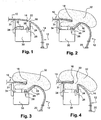
- FIG. 1 a front of a motor vehicle, comprising a hood 10 and a front wing 12, located on the left of the driver.
- a hood of a motor vehicle means the bodywork immediately adjacent to the upper edge of the front left or right wing of the motor vehicle, including what is called the bonnet liner.
- the hood can be opened, at least partially, to access the engine or the trunk.
- fusible link is understood to mean a link capable of breaking (breaking, unhooking), and by permanent connection, a non-fusible link.
- the front wing 12 has an outer skin 14, intended to be seen from outside the motor vehicle.
- This skin 14 has an upper edge 16, which abuts a left edge 18 of the hood, and a lower edge 20, generally connected to the vehicle structure.
- the edge 16 of the skin 14 and the edge 18 of the cap 10 are separated by a clearance 22.
- the front wing 12 comprises, perpendicularly to its upper edge 16 and the inner side of the front face, a substantially vertical wall 24, making up a wing return, allowing on the one hand the attachment of the front wing 12 on the structure of the vehicle and secondly the stiffening of the wing. Fixing to the structure is achieved by a flange 26 of the end of the vertical wall 24, which is fixed to a structural part 30 by fastening means 28.
- structural member 30 is meant any element, relatively rigid, connected to the vehicle frame, and adapted to support inserts on the motor vehicle, such as the wing 12, other body parts, or functional organs .
- the structural part 30 is a left upper spar of the vehicle.
- the area constituted by the edges 18, 16, and by the play 22, can be particularly dangerous. Indeed, in case of accident with a pedestrian in front of the vehicle, the head of the pedestrian can impact.
- the front face of the motor vehicle comprises an airbag 32, folded into a housing 34.
- the airbag 32 is commonly referred to by the trademark "Airbag”.
- unrepresented detection means generally located on the front bumper of the vehicle, activate the airbag 32 in a manner known per se. Once activated, the airbag 32 fills with gas so as to deploy towards the outside of the vehicle, to cover part of the bodywork and to dampen the impact between this part and the pedestrian.
- the airbag 32 is fixed to the structural part 30, so as to have its base, during its deployment generally brutal, firmly attached to the vehicle.
- a part 31 is firmly fixed to the structural part 30 so as to separate the part of the front face comprising the airbag 32 from the remainder of the front face. With this piece, during its deployment, the cushion is oriented towards the game 22.
- This piece 31 can be a functional body of the front technical. It is not essential for the deployment of the cushion to the outside, it can be guided by special seams.
- the cushion 32 once deployed, covers the dangerous edges 18, 16.
- the airbag 32 has exerted pressure on the various organs surrounding it, among which the cover 10, the piece 31 and the wall 24 of the wing 12 which is plastic.
- the wing 12 is more flexible than the hood, it has less resistance than other organs and was deformed first under this pressure. More precisely, the vertical wall 24 of the wing has pivoted around its edge 26, firmly fixed to the structural part 30.
- the fixing means 20 of the lower part of the wing are permanent, and the deformed wing is retained on the vehicle structure by these means as well as the wall 24.
- the cover 10 is stiffer than the wing 12 and it has not deformed.
- the vehicle comprises a cover 13 and a wing 15 such that the wing 15 is stronger than the cover 13. Then, during the deployment of the airbag, it is the edge 18 of the cover 13 only which has deformed from to enlarge the game 22.
- the airbag 32 is located inside the front wing 12.
- the housing 34 is fixed under the wing 12, between the vertical wall 24 and the inner surface 36 of the wing 12.
- the inner surface 36 may be covered with a protective film (not shown) to anticipate the risk of breakage on the surface of the wing 12.
- the rim 26 of the vertical wall 24 is fixed to the structural part 30, thanks to a fusible fixing means 38 which is strong enough to maintain the wing but not enough to withstand the pressure of the airbag 32 during its deployment.
- the fusible fixing means 38 is for example a plastic rivet.
- the airbag 32 When the airbag 32 is deployed, it exerts pressure on the inner surface 36 of the skin 14 and on the wall 24, and thus on the fastening means 38, to the point of breaking them.
- the rim 26 of the wing 12 is detached from the structural part 30 so as to increase the clearance 22 so that the airbag 32 covers the end 18 of the cover 10.
- the wing 12 has distorted to let the cushion 32 unfold.
- the wing 12 is retained in the structure, thus avoiding any danger of projection to the outside of the vehicle.
- the wing return is constituted by a wall 25, having a necking of thickness 40 in the vicinity of the edge 16 and fixed on the structural part 30 thanks to the permanent fixing 28.
- reinforcements 42 and 44 are arranged inside the wing 12, in the vicinity of the edge 16 and the rim 26.
- the airbag 32 when the airbag 32 deploys inside the wing 12, it exerts a pressure on the inner surface 36 and the wall 25, in particular at the necking thickness 40. Under this pressure, and because of the fragility of the wall at the necking 40, the wall 25 is broken, which allows the airbag 32 to come out of the vehicle, enlarging the game 22.
- the upper part of the wing 12 is released by the rupture of the zone 40, but remains maintained on the motor vehicle thanks to the attachment point 20.
- the wing 12 is fixed to the vehicle structure by an arm 46, pivotally mounted about an axis of rotation 48, fixed to the vehicle structure.
- the arm 46 is fixed rigidly to the flange 12, at the edge 16, for example by gluing, screwing or welding.
- the arm 46 serves as a means of attaching the wing to the vehicle structure.
- the arm 46 is also connected to the structural part 30 by a bar 50, perpendicular to the arm.
- This bar 50 is fusibly attached to the part 30.
- the airbag 32 is, in this embodiment, fixed to the structural part 30 between a vertical wall 51 of the latter and the arm 46, above the bar 50.
- the cushion 32 could also, in other embodiments (not shown), be fixed on the bar 50 or the arm 46.
- the cushion When the cushion unfolds, it exerts a pressure on the bar 50, on the arm 46 and on the inner face of the cover 10. This increasing pressure, the fusible attachment of the bar 50 to the piece 30 gives way, the arm 46 is pushed towards the outside of the vehicle, causing the deformation of the wing 12 of plastic material.
- the bar pivots about the axis 48 and the clearance 22 between the edge 18 of the hood 10 and the edge 16 of the wing increases, leaving a passage for the airbag.
- the pivoting arm 46 is a wall pivoting about an axis of rotation connected to the structure, and the bar 50 is a horizontal wall.
- the pivoting arm 46 is electrically controlled.
- another signal automatically controls the pivoting of the arm 46 about the axis 48.
- the wing 12 is no longer deformed only by the pressure of the airbag 32 but also by the movement of the arm 46. The deployment of the airbag 32 out of the vehicle is thus facilitated.
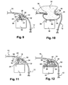
- the rim 26 of the vertical wall 24 is connected to the structural part 30 by a fusible fixing means 38.
- the casing 34 of the cushion 32 is arranged between the wall 24 of the wing and its inner surface 36.
- the housing 34 is no longer directly attached to the structural part 30 but wrapped in a casing 52 and attached to the vehicle with the wing 12.
- This envelope 52 is made of a relatively flexible material, aluminum sheet or plastic. It is fixed to the structural part 30 by means of a permanent fixing 54. It is also fixed to the vertical wall 24 of the wing 12 by a permanent fixing 56.
- the envelope 52 surrounds the cushion 32 in the rest position so that when it unfolds, the envelope 52 interposes between the cushion and the sharp edges he meets to protect him.
- the ends of the envelope 52 are large enough to cover the edges 16 and 18.
- the airbag 32 When the airbag 32 unfolds, as seen on the figure 10 it exerts a pressure on the entire surface of the casing 52 and pulls on the fusible attachment 38.
- the casing 52 being more resistant to this pressure than the attachment 38, the deployment of the airbag 32 breaks the attachment 38.
- the wing 12 is deformed so that its vertical wall 24 undergoes an outward movement, enlarging the game 22 so that the airbag 32 covers the edge 18 of the hood and continue its deployment outside the vehicle.
- the envelope 52 is stretched, so as to guide the cushion 32 to the outside of the vehicle and prevent it from infiltrating inside the wing.
- the casing 52 makes it possible to retain the end 26 of the wing 12 on the motor vehicle.
- the fasteners 54 to the structural part 30 and 56 to the wall 24 of the wing 12 are strong enough not to be broken during the deployment of the cushion 32.
- the end 26 of the wing 12 n is not completely free, which avoids the projection of the wing 12 or its end outwardly and therefore a danger for other pedestrians.
- the envelope 52 has a dual protective role. On the one hand, it protects the airbag 32 during its deployment, being large enough to cover the sharp edges it meets and prevent it from tearing. For this, the envelope is plated on the sharp edges when it opens. On the other hand, it protects the wing 12 during the explosion due to the release of the cushion. Indeed, it deploys initially in the envelope, then deforms the wing, which prevents it from breaking because of the explosion. In addition, the casing 52 protects the cushion 32 from the outside environment, when the latter is in the rest position.
- the casing 52 is no longer attached to the structural part 30 but to the wing return, more precisely a wall 27, by means of permanent fasteners 58 and 60.
- the wall 27, fixed to the structural part 30 by the permanent fixation 28 comprises a thinness of thickness at a zone 62 located between the two permanent fasteners 58 and 60.
- the cushion 32 During the deployment of the cushion 32, it exerts pressure on the entire envelope 52 and on a portion of the wall 27, and pulls on the necking 62. Under the effect of pressure, this necking 62 breaks, so as to leave a passage for the cushion 32 which then enlarges the game 22 to deploy outside the vehicle. As the ends of the envelope 52 overlap when the cushion is at rest, they surround it during its deployment so as to protect it from the outside.
- the casing 52 constitutes a guide means of the airbag during its deployment and a retaining means of the free end of the wing 12 when the wall 27 has been broken.
- the casing 52 is replaced by a cable also attached to the wing and possibly to the structural part 30.
- the cable no longer has the guiding function that brings the envelope 52, it has only a function of retaining the end of the wing 12 to the vehicle structure.
- the wing 12 is connected to the structural part 30 by means of a wing support respectively 64 and 66.
- the wing supports 64 and 66 have a support function and of airbag guide 32.
- the casing 52 is always arranged around the airbag 32. It is fixed to the supports 64, 66 and to the structure 30 by means of fastening tabs. Thanks to these tabs, the housing 34, and therefore the cushion 32 during its deployment, are not in contact with the fastening means of the casing 52 on the vehicle, which avoids risks of tearing of the cushion 32.
- the support 64 is a plate, firmly fixed to the structural part 30.
- the flange 26 of the flange 12 is fixed to the support 64 by a fusible fastener 68.
- a fastening tab of the casing 52 is fixed in such a way solid to the vertical wall 24 through a fastener 56.
- a second fastening lug of the casing 52 is fixed to the reinforcement 64, by a permanent attachment 72.
- the airbag 32 During the deployment of the airbag 32, it exerts pressure on the entire envelope 52 and indirectly on the fusible fastening means 68 which breaks, creating a passage for the cushion 32 so that it unfolds. to the outside by enlarging the game 22.
- the support 66 of the figure 13 is fixed to the structural part 30 by means of a permanent fixing 74.
- the wing 12 does not have an inner vertical wall but just a flange 75 under the edge 16.
- the support 66 is also fixed this flange 75 by a fixing means 76, also permanent.
- the support 66 comprises a plate 80 arranged directly on the structural part 30 and a vertical wall 82, perpendicular to this plate 80 is directed upwards, between the plate 80 and the flange 75.
- This vertical wall 82 comprises a zone 84. necking, where the thickness of plastic is smaller than on the rest of the wall 82.
- An attachment lug of the casing 52 is integral with this vertical wall 82 by means of the permanent fixing 76, and another fixing lug is secured to the plate 80 by means of a permanent fixing 78.
- This zone 84 breaks and leaves a passage for the cushion 32 to unfold. towards the outside of the vehicle, by enlarging the clearance 22.
- the remaining portion of the wall 82 serves to guide the cushion 32 outwardly and prevents inflation of the cushion under the hood 10.
- supports 64 and 66 constitute a support of the casing 34 of the bag 32.
- the pad 32, the casing 34, and the casing 52 are directly fixed on the support 64 or 66, which is then fixed to the wing 12 by means of the fasteners 68 and 76.
- the wing 12, comprising the cushion 32 is fixed on the vehicle, in particular on the structural part 30. This method allows therefore limit the number of mounting operations on the vehicle structure, reducing the occupation of it on the assembly line.
- the wing 12 comprising such supports 64 or 66 with the airbag may constitute a wing module, on which are also reported other functional organ supports, such as a washer housing support. ice, optical media, etc.
- This wing module then attached to the motor vehicle, has the advantage of presenting a module "ready to mount" for the car manufacturer.
- the vehicle is equipped with three airbags (88, 90, 92).
- the juxtaposition of these airbags can cover a much larger area of the wing-hood junction, including other hazardous areas such as the technical front cross member, the shock cups, the battery, the optical brackets , the awning area including the axes and squeegees wipers.
- the airbags are dimensioned differently according to their position on the vehicle and more precisely along the wing-hood junction. Indeed, it is known that the area of the wing-hood junction located near the bumper must protect a pedestrian the size of a child, while the area further to the rear windshield should rather protect a pedestrian adult size. Therefore, the cushion 88 may be a smaller or more flexible cushion to protect a child and the cushion 92 a stiffer and larger cushion to protect an adult. It will be noted that this feature may be present at the front of a vehicle without requiring the airbag to increase the clearance left by the hood and the wing.
Landscapes
- Engineering & Computer Science (AREA)
- Mechanical Engineering (AREA)
- Chemical & Material Sciences (AREA)
- Combustion & Propulsion (AREA)
- Transportation (AREA)
- Body Structure For Vehicles (AREA)
- Superstructure Of Vehicle (AREA)
- Air Bags (AREA)
Claims (26)
- Verwendung eines Kotflügels (12) und einer Motorhaube (10) an der Vorderseite eines Kraftfahrzeugs, die eine Verbindung Kotflügel-Motorhaube bilden, welche ein vordefiniertes Spiel (22) zwischen einem Rand (18) der Motorhaube und einem Rand (16) des Kotflügels aufweist, in Kombination mit einem Airbag (32), der dazu bestimmt sich, sich außerhalb des Fahrzeugs zu entfalten, dadurch gekennzeichnet, dass der Airbag (32) während seiner Entfaltung den Kotflügel (12) derart verformt, dass das Spiel (22) vergrößert und ein Durchlass zwischen dem Rand (18) der Motorhaube und dem Rand (16) des Kotflügels für den Airbag geschaffen wird.
- Verwendung eines Kotflügels und einer Motorhaube nach Anspruch 1 in Kombination mit mehreren Airbags (88, 90, 92).
- Verwendung eines Kotflügels und einer Motorhaube nach Anspruch 2, bei der jeder Airbag in Abhängigkeit davon, ob er dazu bestimmt ist, einen Erwachsenen oder ein Kind zu schützen, unterschiedlich dimensioniert ist.
- Verwendung eines Kotflügels und einer Motorhaube nach einem der Ansprüche 1 bis 3, bei der der Airbag (32) dazu bestimmt ist, die Verbindung Kotflügel-Motorhaube zu überdecken, während er sich entfaltet.
- Verwendung eines Kotflügels und einer Motorhaube nach einem der Ansprüche 1 bis 4 in Kombination mit Sollbruch-Haltemitteln (38, 40, 62, 68, 84) zum Verbinden des Kotflügels (12) mit der Struktur (30) des Fahrzeugs.
- Vordere Vorrichtung eines Kraftfahrzeugs mit einem Kotflügel (12) und einer Motorhaube (10), die eine Verbindung Kotflügel-Motorhaube bildet, welche ein vordefiniertes Spiel (22) zwischen einem Rand (18) der Motorhaube und einem Rand (16) des Kotflügels aufweist, in Kombination mit einem Airbag (32), der dazu bestimmt sich, sich außerhalb des Fahrzeugs zu entfalten, dadurch gekennzeichnet, dass der Airbag (32) während seiner Entfaltung den Kotflügel (12) derart verformt, dass das Spiel (22) vergrößert und ein Durchlass zwischen dem Rand (18) der Motorhaube und dem Rand (16) des Kotflügels für den Airbag geschaffen wird.
- Vorrichtung nach Anspruch 6 mit einem Mittel (52) zum Zurückhalten des vorderen Kotflügels (12), der durch ein Haltemittel (24, 82) in der normalen Nutzungsposition am Fahrzeug gehalten wird, wobei sich dieses Haltemittel (24, 82) von dem Rückhaltemittel (52) unterscheidet und den Kotflügel freizugeben vermag, wenn es einer Kraft ausgesetzt wird, die eine vordefinierte Schwelle überschreitet, wobei das Rückhaltemittel (52) den von dem Haltemittel (24, 82) freigegebenen Kotflügel (12) zurückzuhalten vermag.
- Vorrichtung nach Anspruch 7, die ein an dem Kotflügel und an einem Strukturteil des Kraftfahrzeugs befestigtes Kabel umfasst.
- Vorrichtung nach Anspruch 7, die eine an dem Kotflügel (12) und an einem Strukturteil (30) des Kraftfahrzeugs befestigte Umhüllung (52) umfasst.
- Vorrichtung nach Anspruch 9, in der die Umhüllung (52) um den Airbag (32) herum angeordnet ist, wenn sich dieser in einer Ruhestellung befindet.
- Vorrichtung nach Anspruch 10, in der die Umhüllung (52) derart in der Nähe eines oberen Rands des Kotflügels befestigt ist, dass sie den Airbag (32) während seiner Entfaltung führt.
- Vorrichtung nach Anspruch 10 oder 11, in der die Umhüllung (52) ausreichende Abmessungen und eine ausreichende Festigkeit aufweist, um den Airbag (32) während seiner Entfaltung zu begleiten und sich zwischen den Rändern (16, 18) des Kotflügels und der Motorhaube und dem Airbag einzufügen, um diesen zu schützen.
- Vorrichtung nach einem der Ansprüche 7 bis 12 aus Blech oder aus Kunststoff.
- Vorrichtung nach einem der vorhergehenden Ansprüche, die ein Tragelement (46, 50) für den vorderen Kotflügel (12) umfasst, das einen oberen Teil (16) des Kotflügels (12) mit der Struktur (30) des Fahrzeugs verbindet, das einen Zapfen (48) aufweist, durch den es mit der Struktur derart verbunden werden kann, dass die Vergrößerung des Spiels (22) ermöglicht wird.
- Vorrichtung nach Anspruch 14, die elektrisch betätigt wird.
- Vorrichtung nach einem der Ansprüche 14 oder 15, in welcher der Airbag (32) so angeordnet ist, dass er gegen das Tragelement (46, 50) drückt.
- Vorrichtung nach einem der vorhergehenden Ansprüche, die ein Tragelement (64, 66) für den vorderen Kotflügel (12) umfasst, das einen oberen Teil (16) des Kotflügels mit der Struktur (30) des Fahrzeugs verbindet, wobei das Tragelement eine Aufnahme für einen Airbag (32) aufweist, der zwischen der Innenseite (36) des Kotflügels (12) und der Struktur (30) des Fahrzeugs angeordnet ist.
- Vorrichtung nach Anspruch 17, in der das Tragelement auf der Seite der Struktur (30) eine Sohle (64, 80) aufweist, die als Auflagefläche für den Airbag (32) während seiner Entfaltung dient.
- Vorrichtung nach einem der Ansprüche 17 und 18, in der das Tragelement einen Bereich (68, 84) aufweist, der unter der Schubwirkung des Airbags (32) zu brechen vermag, um den oberen Teil (16) des Kotflügels freizugeben.
- Vorrichtung nach einem der vorhergehenden Ansprüche, in welcher der Kotflügel eine Karosserieverkleidung (14) aufweist, die die Innenseite und die Außenseite des Kotflügels trennt und durch einen Rand (16) abgeschlossen ist, der dazu bestimmt ist, an eine Motorhaube (10) anzugrenzen, sowie eine Aufnahme für einen Airbag, der auf der Innenseite des Kotflügels (12) in der Umgebung des Rands (16) angeordnet ist.
- Vorrichtung nach Anspruch 20, in welcher der Kotflügel aus Kunststoff oder Blech ausgeführt ist.
- Vorrichtung nach Anspruch 20 oder 21, in welcher der Kotflügel ein Mittel (24) zum Halten in der normalen Nutzungsposition am Fahrzeug aufweist und das Haltemittel (24) aus einem Material mit der Verkleidung (14) hergestellt ist und einen Bereich (40, 62) aufweist, der zu brechen vermag.
- Vorrichtung nach einem der Ansprüche 1 bis 22, in der die Motorhaube einen verformbaren Rand (18) umfasst, der während der Entfaltung des Airbags (32) verformt wird, wobei die Motorhaube eventuell aus Kunststoff, aus Blech oder einem Metall-Kunststoff-Hybrid ausgeführt ist.
- Vorderer Kotflügel, der als Bestandteil einer Vorrichtung nach einem der Ansprüche 6 bis 23 vorgesehen ist.
- Vorderes Kotflügelmodul eines Kraftfahrzeugs, das einen vorderen Kotflügel (12) und ein Kotflügel-Tragelement (46, 50, 64, 66) umfasst, das als Bestandteil einer Vorrichtung nach einem der Ansprüche 6 bis 23 vorgesehen ist.
- Kotflügelmodul nach Anspruch 25, das Tragelemente für Funktionselemente aufweist.
Applications Claiming Priority (2)
| Application Number | Priority Date | Filing Date | Title |
|---|---|---|---|
| FR0310633A FR2859444B1 (fr) | 2003-09-09 | 2003-09-09 | Utilisation d'aile et d'un capot en combinaison avec un coussin gonflable, moyen de retenue et support d'aile, aile, module d'aile et capot d'un vehicule automobile |
| FR0310633 | 2003-09-09 |
Publications (2)
| Publication Number | Publication Date |
|---|---|
| EP1514768A1 EP1514768A1 (de) | 2005-03-16 |
| EP1514768B1 true EP1514768B1 (de) | 2008-05-14 |
Family
ID=34130782
Family Applications (1)
| Application Number | Title | Priority Date | Filing Date |
|---|---|---|---|
| EP04292156A Expired - Lifetime EP1514768B1 (de) | 2003-09-09 | 2004-09-08 | Gebrauchsverfahren fur einem Kotflügel und eine Motorhaube, mit einem Luftkissen und einem Kotflügel Stutz , Kfz-Kotflügel, Kfz-Kotflügelmodul, und Kfz-Motorhaube |
Country Status (6)
| Country | Link |
|---|---|
| US (1) | US7150495B2 (de) |
| EP (1) | EP1514768B1 (de) |
| AT (1) | ATE395239T1 (de) |
| DE (1) | DE602004013691D1 (de) |
| ES (1) | ES2305686T3 (de) |
| FR (1) | FR2859444B1 (de) |
Families Citing this family (29)
| Publication number | Priority date | Publication date | Assignee | Title |
|---|---|---|---|---|
| FR2850348B1 (fr) * | 2003-01-29 | 2005-07-15 | Plastic Omnium Cie | Aile de vehicule automobile ayant une zone fusible |
| US7374231B2 (en) * | 2004-04-02 | 2008-05-20 | Gm Global Technology Operations, Inc. | Force and deceleration delimiting devices and methods for operating the same |
| US7637559B2 (en) | 2004-04-02 | 2009-12-29 | Gm Global Technology Operations, Inc. | Volume-filling mechanical assemblies and methods of operating the same |
| US20050218696A1 (en) * | 2004-04-02 | 2005-10-06 | Aase Jan H | Methods for modifying a crash deceleration pulse |
| US7401846B2 (en) * | 2004-04-02 | 2008-07-22 | Gm Global Technology Operations, Inc. | Volume-filling mechanical assemblies and methods of operating the same |
| US7494179B2 (en) * | 2005-04-26 | 2009-02-24 | Zephyros, Inc. | Member for baffling, reinforcement or sealing |
| US8381403B2 (en) | 2005-05-25 | 2013-02-26 | Zephyros, Inc. | Baffle for an automotive vehicle and method of use therefor |
| DE102005049945A1 (de) * | 2005-10-19 | 2007-04-26 | GM Global Technology Operations, Inc., Detroit | Windschutzscheibenanordnung |
| JP4775079B2 (ja) * | 2006-04-03 | 2011-09-21 | 日産自動車株式会社 | 車体前部構造 |
| US7527121B2 (en) * | 2006-12-28 | 2009-05-05 | Toyoda Gosei Co., Ltd. | Pedestrian protection air bag system |
| JP4919409B2 (ja) * | 2007-01-24 | 2012-04-18 | ルネサスエレクトロニクス株式会社 | 半導体装置製造方法 |
| JP2009101793A (ja) * | 2007-10-22 | 2009-05-14 | Toyoda Gosei Co Ltd | 歩行者用エアバッグ装置 |
| JP2010149753A (ja) * | 2008-12-25 | 2010-07-08 | Toyoda Gosei Co Ltd | 歩行者用エアバッグ装置 |
| GB2475326A (en) * | 2009-11-16 | 2011-05-18 | Autoliv Dev | Inflatable battery protector |
| US20120211297A1 (en) * | 2010-03-05 | 2012-08-23 | Ralston Daniel D | Hood pedestrian energy absorber |
| WO2011109718A2 (en) | 2010-03-05 | 2011-09-09 | Shape Corp. | Hood pedestrian energy absorber |
| US8424629B2 (en) | 2011-03-09 | 2013-04-23 | Shape Corp. | Vehicle energy absorber for pedestrian's upper leg |
| KR101198842B1 (ko) * | 2011-05-23 | 2012-11-07 | 기아자동차주식회사 | 차량용 외장에어백 모듈 및 외장에어백 모듈 장착용 백빔 |
| KR101219708B1 (ko) * | 2011-06-17 | 2013-01-21 | 기아자동차주식회사 | 차량용 외장 에어백 |
| US9834171B2 (en) | 2013-05-08 | 2017-12-05 | GM Global Technology Operations LLC | Fender located pedestrian protection airbag |
| US9127968B2 (en) | 2013-11-18 | 2015-09-08 | Ford Global Technologies, Llc | Flexible optical impact detection sensor for front rail mounted airbag |
| US9004216B1 (en) * | 2013-11-18 | 2015-04-14 | Ford Global Technologies, Llc | Front rail mounted airbag |
| DE102014222949A1 (de) | 2013-11-18 | 2015-05-21 | Ford Global Technologies, Llc | Flexibler elektroresisitiver Aufprallerkennungssensor für am vorderen 'Träger befestigten Airbag |
| KR101558763B1 (ko) * | 2014-04-25 | 2015-10-12 | 현대자동차주식회사 | 차량의 보행자 에어백 시스템 |
| JP6971200B2 (ja) * | 2018-06-04 | 2021-11-24 | 本田技研工業株式会社 | 衝突物保護装置 |
| JP7008582B2 (ja) * | 2018-06-08 | 2022-01-25 | 本田技研工業株式会社 | 車体前部構造 |
| US11491950B2 (en) * | 2021-03-01 | 2022-11-08 | Ford Global Technologies, Llc | Vehicle external airbag |
| US11766990B1 (en) * | 2022-05-12 | 2023-09-26 | Ford Global Technologies, Llc | Vehicle hood assembly including pedestrian airbag |
| DE102024129842B3 (de) * | 2024-10-15 | 2025-12-18 | Dr. Ing. H.C. F. Porsche Aktiengesellschaft | Vorderbau eines Kraftfahrzeugs und Kraftfahrzeug |
Family Cites Families (23)
| Publication number | Priority date | Publication date | Assignee | Title |
|---|---|---|---|---|
| FR2272866B1 (de) * | 1974-05-30 | 1978-12-22 | Peugeot & Renault | |
| DE10222512A1 (de) * | 2002-05-22 | 2003-12-11 | Volkswagen Ag | Energieabsorbierendes Karosserieteil, insbesondere Fronthaube, für ein Fahrzeug, insbesondere Kraftfahrzeug |
| JPH0891170A (ja) * | 1994-09-22 | 1996-04-09 | Toyota Motor Corp | フードエアバッグ装置 |
| JP3687418B2 (ja) * | 1998-06-26 | 2005-08-24 | 日産自動車株式会社 | 跳ね上げフード |
| JP2000264146A (ja) * | 1999-03-12 | 2000-09-26 | Mitsubishi Motors Corp | 車両用歩行者保護装置 |
| DE19918202A1 (de) * | 1999-04-22 | 2000-10-26 | Bayer Ag | Sicherheitsstoßfänger |
| DE19948181B4 (de) | 1999-10-07 | 2012-10-25 | Volkswagen Ag | Aufprall-Schutzvorrichtung |
| DE19959892A1 (de) * | 1999-12-11 | 2001-06-13 | Opel Adam Ag | Vorderbau für ein Kraftfahrzeug |
| DE10014832B4 (de) * | 2000-03-24 | 2006-05-04 | Volkswagen Ag | Sicherheitssystem für ein Kraftfahrzeug |
| DE10022094B4 (de) * | 2000-05-08 | 2012-07-05 | Volkswagen Ag | Energieabsorbierendes Karosserieteil an einem Fahrzeug |
| JP2001334895A (ja) * | 2000-05-26 | 2001-12-04 | Mazda Motor Corp | 車両用歩行者保護装置 |
| JP3711847B2 (ja) * | 2000-07-27 | 2005-11-02 | 日産自動車株式会社 | 車両用エアバッグ装置 |
| JP4762438B2 (ja) * | 2001-05-18 | 2011-08-31 | 富士重工業株式会社 | 車両の前部車体構造 |
| JP3791379B2 (ja) * | 2001-10-02 | 2006-06-28 | トヨタ自動車株式会社 | フードエアバッグ装置 |
| JP3794325B2 (ja) * | 2001-12-27 | 2006-07-05 | トヨタ自動車株式会社 | 自動車のフード構造 |
| JP3928442B2 (ja) * | 2002-02-26 | 2007-06-13 | 豊田合成株式会社 | 歩行者用エアバッグ装置 |
| JP3941584B2 (ja) * | 2002-05-09 | 2007-07-04 | トヨタ自動車株式会社 | 歩行者保護用エアバッグ装置 |
| DE10239352A1 (de) * | 2002-08-28 | 2004-03-11 | Rach, Barbara | Sicherheitseinrichtung für ein Fahrzeug zum Schutz von Fußgängern oder dergleichen |
| JP3975866B2 (ja) * | 2002-08-30 | 2007-09-12 | 豊田合成株式会社 | 歩行者保護用エアバッグ装置 |
| ITTV20020103A1 (it) * | 2002-09-09 | 2004-03-10 | Plastal Spa | Struttura di frontale per veicolo, del tipo con controllo |
| DE10254733A1 (de) * | 2002-11-23 | 2004-06-17 | Bayerische Motoren Werke Ag | Kraftfahrzeug |
| FR2850348B1 (fr) * | 2003-01-29 | 2005-07-15 | Plastic Omnium Cie | Aile de vehicule automobile ayant une zone fusible |
| US7341274B2 (en) * | 2004-03-17 | 2008-03-11 | Toyoda Gosei Co., Ltd. | Pedestrian airbag system |
-
2003
- 2003-09-09 FR FR0310633A patent/FR2859444B1/fr not_active Expired - Fee Related
-
2004
- 2004-09-08 ES ES04292156T patent/ES2305686T3/es not_active Expired - Lifetime
- 2004-09-08 DE DE602004013691T patent/DE602004013691D1/de not_active Expired - Lifetime
- 2004-09-08 AT AT04292156T patent/ATE395239T1/de not_active IP Right Cessation
- 2004-09-08 US US10/936,219 patent/US7150495B2/en not_active Expired - Fee Related
- 2004-09-08 EP EP04292156A patent/EP1514768B1/de not_active Expired - Lifetime
Also Published As
| Publication number | Publication date |
|---|---|
| ATE395239T1 (de) | 2008-05-15 |
| US20050140174A1 (en) | 2005-06-30 |
| DE602004013691D1 (de) | 2008-06-26 |
| EP1514768A1 (de) | 2005-03-16 |
| FR2859444B1 (fr) | 2006-02-03 |
| FR2859444A1 (fr) | 2005-03-11 |
| US7150495B2 (en) | 2006-12-19 |
| ES2305686T3 (es) | 2008-11-01 |
Similar Documents
| Publication | Publication Date | Title |
|---|---|---|
| EP1514768B1 (de) | Gebrauchsverfahren fur einem Kotflügel und eine Motorhaube, mit einem Luftkissen und einem Kotflügel Stutz , Kfz-Kotflügel, Kfz-Kotflügelmodul, und Kfz-Motorhaube | |
| EP0529389B1 (de) | Sicherheitseinrichtung in Form eines Gaskissens für Kraftfahrzeug | |
| EP2334520B1 (de) | Innenbekleidungseinheit für kraftfahrzeug und kraftfahrzeug | |
| FR2925410A1 (fr) | Planche de bord amelioree | |
| EP2052919A1 (de) | Sicherheitsvorrichtung mit Airbag für Kraftfahrzeug | |
| EP0953484B1 (de) | Seitenairbagmodul- Montagevorrichtung für einen Vordersitz eines Kraftfahrzeuges | |
| EP1747125A1 (de) | Stützelement für ein autoteil | |
| EP1601558B1 (de) | Schutzvorrichtung gegen stösse für eine fahrzeugvorderseite | |
| EP3099533B1 (de) | Vorrichtung zur befestigung einer sonnenblende und eines airbagmoduls | |
| FR2852564A1 (fr) | Dispositif de protection contre les chocs pour une face avant de vehicule automobile | |
| EP2379374A1 (de) | Bewegliche scharniergelenkhalterung für fussgägner-stossdämpfer | |
| EP1100698B1 (de) | Airbaganordnung zum kraftfahrzeuginsassenschutz bei seitenaufprall | |
| FR3089178A1 (fr) | Module de face avant pour véhicule automobile | |
| FR3106115A1 (fr) | Dispositif de sécurité de volant de véhicule | |
| EP2424751B1 (de) | Hekklapperaum und eine heckklappe mit sicherheitsanordnungen | |
| EP4274766B1 (de) | Schutzmodul für kraftfahrzeuge zum schutz eines fussgängers bei einem aufprall | |
| FR2818706A1 (fr) | Dispositif de fixation securise pour la fixation d'accessoires sur un vehicule | |
| FR2947226A1 (fr) | Agencement pour coussin de securite gonflable equipant une planche de bord de vehicule automobile comprenant un volet articule | |
| FR3105125A1 (fr) | Véhicule à sac gonflable se déployant depuis le toit entre un siège et une planche de bord | |
| FR2925000A1 (fr) | Volet deformable de boitier de coussin gonflable. | |
| FR3166113A1 (fr) | Système de protection pour un passager avant d’un véhicule automobile | |
| FR3096943A1 (fr) | Couvercle servant a recouvrir un dispositif de securite dans un vehicule | |
| FR3118740A1 (fr) | Module de protection pour vehicule automobile destine a proteger un pieton lors d’un choc | |
| FR3165842A1 (fr) | Volant de direction pour véhicule automobile comprenant un airbag déporté | |
| FR3158687A1 (fr) | Ensemble pour planche de bord de véhicule automobile et véhicule automobile comprenant un tel ensemble |
Legal Events
| Date | Code | Title | Description |
|---|---|---|---|
| PUAI | Public reference made under article 153(3) epc to a published international application that has entered the european phase |
Free format text: ORIGINAL CODE: 0009012 |
|
| AK | Designated contracting states |
Kind code of ref document: A1 Designated state(s): AT BE BG CH CY CZ DE DK EE ES FI FR GB GR HU IE IT LI LU MC NL PL PT RO SE SI SK TR |
|
| AX | Request for extension of the european patent |
Extension state: AL HR LT LV MK |
|
| 17P | Request for examination filed |
Effective date: 20050915 |
|
| AKX | Designation fees paid |
Designated state(s): AT BE BG CH CY CZ DE DK EE ES FI FR GB GR HU IE IT LI LU MC NL PL PT RO SE SI SK TR |
|
| 17Q | First examination report despatched |
Effective date: 20061208 |
|
| GRAP | Despatch of communication of intention to grant a patent |
Free format text: ORIGINAL CODE: EPIDOSNIGR1 |
|
| GRAS | Grant fee paid |
Free format text: ORIGINAL CODE: EPIDOSNIGR3 |
|
| GRAA | (expected) grant |
Free format text: ORIGINAL CODE: 0009210 |
|
| AK | Designated contracting states |
Kind code of ref document: B1 Designated state(s): AT BE BG CH CY CZ DE DK EE ES FI FR GB GR HU IE IT LI LU MC NL PL PT RO SE SI SK TR |
|
| REG | Reference to a national code |
Ref country code: GB Ref legal event code: FG4D Free format text: NOT ENGLISH |
|
| REG | Reference to a national code |
Ref country code: CH Ref legal event code: EP |
|
| REG | Reference to a national code |
Ref country code: IE Ref legal event code: FG4D |
|
| REF | Corresponds to: |
Ref document number: 602004013691 Country of ref document: DE Date of ref document: 20080626 Kind code of ref document: P |
|
| PG25 | Lapsed in a contracting state [announced via postgrant information from national office to epo] |
Ref country code: SI Free format text: LAPSE BECAUSE OF FAILURE TO SUBMIT A TRANSLATION OF THE DESCRIPTION OR TO PAY THE FEE WITHIN THE PRESCRIBED TIME-LIMIT Effective date: 20080514 |
|
| PG25 | Lapsed in a contracting state [announced via postgrant information from national office to epo] |
Ref country code: FI Free format text: LAPSE BECAUSE OF FAILURE TO SUBMIT A TRANSLATION OF THE DESCRIPTION OR TO PAY THE FEE WITHIN THE PRESCRIBED TIME-LIMIT Effective date: 20080514 |
|
| REG | Reference to a national code |
Ref country code: ES Ref legal event code: FG2A Ref document number: 2305686 Country of ref document: ES Kind code of ref document: T3 |
|
| NLV1 | Nl: lapsed or annulled due to failure to fulfill the requirements of art. 29p and 29m of the patents act | ||
| PG25 | Lapsed in a contracting state [announced via postgrant information from national office to epo] |
Ref country code: NL Free format text: LAPSE BECAUSE OF FAILURE TO SUBMIT A TRANSLATION OF THE DESCRIPTION OR TO PAY THE FEE WITHIN THE PRESCRIBED TIME-LIMIT Effective date: 20080514 Ref country code: AT Free format text: LAPSE BECAUSE OF FAILURE TO SUBMIT A TRANSLATION OF THE DESCRIPTION OR TO PAY THE FEE WITHIN THE PRESCRIBED TIME-LIMIT Effective date: 20080514 Ref country code: PL Free format text: LAPSE BECAUSE OF FAILURE TO SUBMIT A TRANSLATION OF THE DESCRIPTION OR TO PAY THE FEE WITHIN THE PRESCRIBED TIME-LIMIT Effective date: 20080514 |
|
| REG | Reference to a national code |
Ref country code: IE Ref legal event code: FD4D |
|
| PG25 | Lapsed in a contracting state [announced via postgrant information from national office to epo] |
Ref country code: IE Free format text: LAPSE BECAUSE OF FAILURE TO SUBMIT A TRANSLATION OF THE DESCRIPTION OR TO PAY THE FEE WITHIN THE PRESCRIBED TIME-LIMIT Effective date: 20080514 Ref country code: PT Free format text: LAPSE BECAUSE OF FAILURE TO SUBMIT A TRANSLATION OF THE DESCRIPTION OR TO PAY THE FEE WITHIN THE PRESCRIBED TIME-LIMIT Effective date: 20081014 Ref country code: SE Free format text: LAPSE BECAUSE OF FAILURE TO SUBMIT A TRANSLATION OF THE DESCRIPTION OR TO PAY THE FEE WITHIN THE PRESCRIBED TIME-LIMIT Effective date: 20080814 Ref country code: DK Free format text: LAPSE BECAUSE OF FAILURE TO SUBMIT A TRANSLATION OF THE DESCRIPTION OR TO PAY THE FEE WITHIN THE PRESCRIBED TIME-LIMIT Effective date: 20080514 |
|
| PG25 | Lapsed in a contracting state [announced via postgrant information from national office to epo] |
Ref country code: SK Free format text: LAPSE BECAUSE OF FAILURE TO SUBMIT A TRANSLATION OF THE DESCRIPTION OR TO PAY THE FEE WITHIN THE PRESCRIBED TIME-LIMIT Effective date: 20080514 Ref country code: RO Free format text: LAPSE BECAUSE OF FAILURE TO SUBMIT A TRANSLATION OF THE DESCRIPTION OR TO PAY THE FEE WITHIN THE PRESCRIBED TIME-LIMIT Effective date: 20080514 |
|
| PLBE | No opposition filed within time limit |
Free format text: ORIGINAL CODE: 0009261 |
|
| STAA | Information on the status of an ep patent application or granted ep patent |
Free format text: STATUS: NO OPPOSITION FILED WITHIN TIME LIMIT |
|
| 26N | No opposition filed |
Effective date: 20090217 |
|
| PG25 | Lapsed in a contracting state [announced via postgrant information from national office to epo] |
Ref country code: BG Free format text: LAPSE BECAUSE OF FAILURE TO SUBMIT A TRANSLATION OF THE DESCRIPTION OR TO PAY THE FEE WITHIN THE PRESCRIBED TIME-LIMIT Effective date: 20080814 Ref country code: EE Free format text: LAPSE BECAUSE OF FAILURE TO SUBMIT A TRANSLATION OF THE DESCRIPTION OR TO PAY THE FEE WITHIN THE PRESCRIBED TIME-LIMIT Effective date: 20080514 Ref country code: MC Free format text: LAPSE BECAUSE OF NON-PAYMENT OF DUE FEES Effective date: 20080930 |
|
| REG | Reference to a national code |
Ref country code: CH Ref legal event code: PL |
|
| REG | Reference to a national code |
Ref country code: FR Ref legal event code: ST Effective date: 20090529 |
|
| REG | Reference to a national code |
Ref country code: FR Ref legal event code: RN |
|
| REG | Reference to a national code |
Ref country code: FR Ref legal event code: FC |
|
| PG25 | Lapsed in a contracting state [announced via postgrant information from national office to epo] |
Ref country code: FR Free format text: LAPSE BECAUSE OF NON-PAYMENT OF DUE FEES Effective date: 20080930 Ref country code: CH Free format text: LAPSE BECAUSE OF NON-PAYMENT OF DUE FEES Effective date: 20080930 Ref country code: LI Free format text: LAPSE BECAUSE OF NON-PAYMENT OF DUE FEES Effective date: 20080930 |
|
| PGRI | Patent reinstated in contracting state [announced from national office to epo] |
Ref country code: FR Effective date: 20100121 |
|
| PG25 | Lapsed in a contracting state [announced via postgrant information from national office to epo] |
Ref country code: LU Free format text: LAPSE BECAUSE OF NON-PAYMENT OF DUE FEES Effective date: 20080908 Ref country code: CY Free format text: LAPSE BECAUSE OF FAILURE TO SUBMIT A TRANSLATION OF THE DESCRIPTION OR TO PAY THE FEE WITHIN THE PRESCRIBED TIME-LIMIT Effective date: 20080514 Ref country code: HU Free format text: LAPSE BECAUSE OF FAILURE TO SUBMIT A TRANSLATION OF THE DESCRIPTION OR TO PAY THE FEE WITHIN THE PRESCRIBED TIME-LIMIT Effective date: 20081115 |
|
| PG25 | Lapsed in a contracting state [announced via postgrant information from national office to epo] |
Ref country code: TR Free format text: LAPSE BECAUSE OF FAILURE TO SUBMIT A TRANSLATION OF THE DESCRIPTION OR TO PAY THE FEE WITHIN THE PRESCRIBED TIME-LIMIT Effective date: 20080514 |
|
| PG25 | Lapsed in a contracting state [announced via postgrant information from national office to epo] |
Ref country code: GR Free format text: LAPSE BECAUSE OF FAILURE TO SUBMIT A TRANSLATION OF THE DESCRIPTION OR TO PAY THE FEE WITHIN THE PRESCRIBED TIME-LIMIT Effective date: 20080815 |
|
| PGFP | Annual fee paid to national office [announced via postgrant information from national office to epo] |
Ref country code: IT Payment date: 20100922 Year of fee payment: 7 |
|
| PG25 | Lapsed in a contracting state [announced via postgrant information from national office to epo] |
Ref country code: IT Free format text: LAPSE BECAUSE OF NON-PAYMENT OF DUE FEES Effective date: 20120908 |
|
| PG25 | Lapsed in a contracting state [announced via postgrant information from national office to epo] |
Ref country code: BE Free format text: LAPSE BECAUSE OF NON-PAYMENT OF DUE FEES Effective date: 20140930 |
|
| PGFP | Annual fee paid to national office [announced via postgrant information from national office to epo] |
Ref country code: ES Payment date: 20151028 Year of fee payment: 12 Ref country code: BE Payment date: 20150929 Year of fee payment: 12 |
|
| REG | Reference to a national code |
Ref country code: FR Ref legal event code: PLFP Year of fee payment: 13 |
|
| PG25 | Lapsed in a contracting state [announced via postgrant information from national office to epo] |
Ref country code: BE Free format text: LAPSE BECAUSE OF NON-PAYMENT OF DUE FEES Effective date: 20160930 |
|
| REG | Reference to a national code |
Ref country code: FR Ref legal event code: PLFP Year of fee payment: 14 |
|
| REG | Reference to a national code |
Ref country code: BE Ref legal event code: MM Effective date: 20160930 |
|
| PG25 | Lapsed in a contracting state [announced via postgrant information from national office to epo] |
Ref country code: ES Free format text: LAPSE BECAUSE OF NON-PAYMENT OF DUE FEES Effective date: 20160909 |
|
| REG | Reference to a national code |
Ref country code: FR Ref legal event code: PLFP Year of fee payment: 15 |
|
| PGFP | Annual fee paid to national office [announced via postgrant information from national office to epo] |
Ref country code: FR Payment date: 20180926 Year of fee payment: 15 Ref country code: DE Payment date: 20180920 Year of fee payment: 15 |
|
| REG | Reference to a national code |
Ref country code: ES Ref legal event code: FD2A Effective date: 20181128 |
|
| PGFP | Annual fee paid to national office [announced via postgrant information from national office to epo] |
Ref country code: CZ Payment date: 20180906 Year of fee payment: 15 Ref country code: GB Payment date: 20180919 Year of fee payment: 15 |
|
| REG | Reference to a national code |
Ref country code: DE Ref legal event code: R119 Ref document number: 602004013691 Country of ref document: DE |
|
| PG25 | Lapsed in a contracting state [announced via postgrant information from national office to epo] |
Ref country code: CZ Free format text: LAPSE BECAUSE OF NON-PAYMENT OF DUE FEES Effective date: 20190908 |
|
| PG25 | Lapsed in a contracting state [announced via postgrant information from national office to epo] |
Ref country code: DE Free format text: LAPSE BECAUSE OF NON-PAYMENT OF DUE FEES Effective date: 20200401 |
|
| GBPC | Gb: european patent ceased through non-payment of renewal fee |
Effective date: 20190908 |
|
| PG25 | Lapsed in a contracting state [announced via postgrant information from national office to epo] |
Ref country code: FR Free format text: LAPSE BECAUSE OF NON-PAYMENT OF DUE FEES Effective date: 20190930 Ref country code: GB Free format text: LAPSE BECAUSE OF NON-PAYMENT OF DUE FEES Effective date: 20190908 |