EP1601558B1 - Schutzvorrichtung gegen stösse für eine fahrzeugvorderseite - Google Patents
Schutzvorrichtung gegen stösse für eine fahrzeugvorderseite Download PDFInfo
- Publication number
- EP1601558B1 EP1601558B1 EP04719484A EP04719484A EP1601558B1 EP 1601558 B1 EP1601558 B1 EP 1601558B1 EP 04719484 A EP04719484 A EP 04719484A EP 04719484 A EP04719484 A EP 04719484A EP 1601558 B1 EP1601558 B1 EP 1601558B1
- Authority
- EP
- European Patent Office
- Prior art keywords
- compressible member
- impact
- impact element
- mounting block
- breakable means
- Prior art date
- Legal status (The legal status is an assumption and is not a legal conclusion. Google has not performed a legal analysis and makes no representation as to the accuracy of the status listed.)
- Expired - Lifetime
Links
- 239000006260 foam Substances 0.000 claims description 11
- 230000006837 decompression Effects 0.000 claims description 4
- 229920001971 elastomer Polymers 0.000 claims description 4
- 230000003313 weakening effect Effects 0.000 claims description 4
- 239000002360 explosive Substances 0.000 claims description 3
- 239000000463 material Substances 0.000 claims description 3
- 239000004033 plastic Substances 0.000 claims description 3
- 229920003023 plastic Polymers 0.000 claims description 3
- 239000005060 rubber Substances 0.000 claims description 3
- 229920001169 thermoplastic Polymers 0.000 claims description 3
- 239000004416 thermosoftening plastic Substances 0.000 claims description 3
- 230000001413 cellular effect Effects 0.000 claims description 2
- 238000006073 displacement reaction Methods 0.000 claims description 2
- 230000035939 shock Effects 0.000 description 20
- 238000001514 detection method Methods 0.000 description 5
- 238000010521 absorption reaction Methods 0.000 description 3
- 230000006835 compression Effects 0.000 description 3
- 238000007906 compression Methods 0.000 description 3
- 230000001681 protective effect Effects 0.000 description 3
- 241000195940 Bryophyta Species 0.000 description 2
- 235000011929 mousse Nutrition 0.000 description 2
- 239000004743 Polypropylene Substances 0.000 description 1
- 229920005830 Polyurethane Foam Polymers 0.000 description 1
- 238000013270 controlled release Methods 0.000 description 1
- 238000013016 damping Methods 0.000 description 1
- 230000000694 effects Effects 0.000 description 1
- 239000000806 elastomer Substances 0.000 description 1
- -1 polypropylene Polymers 0.000 description 1
- 229920001155 polypropylene Polymers 0.000 description 1
- 239000011496 polyurethane foam Substances 0.000 description 1
- 230000000750 progressive effect Effects 0.000 description 1
Images


Classifications
-
- B—PERFORMING OPERATIONS; TRANSPORTING
- B60—VEHICLES IN GENERAL
- B60R—VEHICLES, VEHICLE FITTINGS, OR VEHICLE PARTS, NOT OTHERWISE PROVIDED FOR
- B60R21/00—Arrangements or fittings on vehicles for protecting or preventing injuries to occupants or pedestrians in case of accidents or other traffic risks
- B60R21/34—Protecting non-occupants of a vehicle, e.g. pedestrians
-
- B—PERFORMING OPERATIONS; TRANSPORTING
- B60—VEHICLES IN GENERAL
- B60Q—ARRANGEMENT OF SIGNALLING OR LIGHTING DEVICES, THE MOUNTING OR SUPPORTING THEREOF OR CIRCUITS THEREFOR, FOR VEHICLES IN GENERAL
- B60Q1/00—Arrangement of optical signalling or lighting devices, the mounting or supporting thereof or circuits therefor
- B60Q1/02—Arrangement of optical signalling or lighting devices, the mounting or supporting thereof or circuits therefor the devices being primarily intended to illuminate the way ahead or to illuminate other areas of way or environments
- B60Q1/04—Arrangement of optical signalling or lighting devices, the mounting or supporting thereof or circuits therefor the devices being primarily intended to illuminate the way ahead or to illuminate other areas of way or environments the devices being headlights
- B60Q1/0491—Shock absorbing devices therefor
- B60Q1/0495—Frangible brackets
-
- B—PERFORMING OPERATIONS; TRANSPORTING
- B60—VEHICLES IN GENERAL
- B60R—VEHICLES, VEHICLE FITTINGS, OR VEHICLE PARTS, NOT OTHERWISE PROVIDED FOR
- B60R21/00—Arrangements or fittings on vehicles for protecting or preventing injuries to occupants or pedestrians in case of accidents or other traffic risks
- B60R21/34—Protecting non-occupants of a vehicle, e.g. pedestrians
- B60R2021/343—Protecting non-occupants of a vehicle, e.g. pedestrians using deformable body panel, bodywork or components
-
- B—PERFORMING OPERATIONS; TRANSPORTING
- B60—VEHICLES IN GENERAL
- B60R—VEHICLES, VEHICLE FITTINGS, OR VEHICLE PARTS, NOT OTHERWISE PROVIDED FOR
- B60R21/00—Arrangements or fittings on vehicles for protecting or preventing injuries to occupants or pedestrians in case of accidents or other traffic risks
- B60R21/34—Protecting non-occupants of a vehicle, e.g. pedestrians
- B60R2021/346—Protecting non-occupants of a vehicle, e.g. pedestrians means outside vehicle body
-
- B—PERFORMING OPERATIONS; TRANSPORTING
- B60—VEHICLES IN GENERAL
- B60R—VEHICLES, VEHICLE FITTINGS, OR VEHICLE PARTS, NOT OTHERWISE PROVIDED FOR
- B60R21/00—Arrangements or fittings on vehicles for protecting or preventing injuries to occupants or pedestrians in case of accidents or other traffic risks
- B60R21/01—Electrical circuits for triggering passive safety arrangements, e.g. airbags, safety belt tighteners, in case of vehicle accidents or impending vehicle accidents
- B60R21/013—Electrical circuits for triggering passive safety arrangements, e.g. airbags, safety belt tighteners, in case of vehicle accidents or impending vehicle accidents including means for detecting collisions, impending collisions or roll-over
- B60R21/0134—Electrical circuits for triggering passive safety arrangements, e.g. airbags, safety belt tighteners, in case of vehicle accidents or impending vehicle accidents including means for detecting collisions, impending collisions or roll-over responsive to imminent contact with an obstacle, e.g. using radar systems
Definitions
- the invention relates to a device for protection against shocks with an impact element of a front face of a motor vehicle according to the preamble of claim 1, see AT-B-362 240.
- impact element any element of the front face, whether apparent or concealed, which is likely to have “hard points”, so dangerous points, in case of shock front.
- Such an impact element may be constituted, for example, by a projector, a lock, a radiator, a cross, and so on. which is integrated in the front face and which is likely to cause serious damage in the event of a frontal impact at low speed, in particular with respect to a pedestrian struck by the motor vehicle.
- the bumper beam also called the Danner beam
- absorbs larger impacts for speeds up to about 15 km / h.
- structural parts of the vehicle frame contribute to the shock absorption at high speed.
- Air bags have also been proposed which, in the event of shock detection, come to expand at the front of the vehicle to cushion the impact on a pedestrian, as taught by the publication EP 1 024 063.
- a first solution is to fix the projectors on the front by fusible tabs which have a pre-calculated area to break under a certain strength by absorbing a portion of the energy.
- the damping provided by these fusible tabs is limited and often insufficient to absorb the energy of a shock against a pedestrian.
- a second solution is to use a mounting plate which serves as an interface between the front face and the projector and which is designed to absorb the energy of a shock by deformation or recoil of the projector.
- this plate is an additional piece of important dimensions which leads to a more complex editing.
- a third solution is to fix the projector with a point of rotation on the front face, the projector being held in position by a spring, see US-A-4070051.
- the shield slides backwards and drives the projector in rotation.
- the point of rotation of the headlamp on impact may create a hard point on the front panel and thus fail to meet the criteria of the pedestrian impact legislation.
- the object of the invention is in particular to overcome the disadvantages of the protective devices of the prior art.
- it aims to provide a device for protection against shocks, likely to provide a gradual shock absorption, in the event of a frontal collision at low speed, in particular with a pedestrian.
- the invention also aims to provide a protection device of this type which is applicable to different impact elements, forming hard points, the front face of the motor vehicle.
- the invention is particularly intended to provide protection vis-à-vis the impacts with the projectors of the front panel.
- the invention proposes for this purpose a protection device of the type defined above, in which the impact element is held in a mounting block forming part of the front face, by means of a compressible member having a face received in the mounting block and an inner face shaped to house the impact member.
- the solution of the invention is to interpose a compressible member between the impact member and a mounting block which is part of the front face.
- This compressible member has shapes adapted to, firstly be received in the mounting block, and secondly accommodate the impact member.
- the inner face of the compressible member is provided with a multiplicity of projections arranged to come into contact with the impact member and thereby limit the contact surface between the member compressible and the impact element. This feature helps to cushion the shock in a progressive way.
- these projections each have substantially the shape of a truncated cone having a large base attached to the inner face of the compressible member and a small clean base to come into contact with the impact member, and admitting an axis of revolution of orientation chosen.
- the axis of revolution may be substantially perpendicular, or inclined, with respect to the inner surface of the compressible member.
- each truncated cone-shaped projection comprises a small base preferably having a diameter of 10 to 20 mm, a large base having a diameter of about 2.5 times the diameter of the small base and a height of 10 to 30 mm.
- the compressible member has, at the level of the projection, a thickness of 10 to 100 mm.
- the compressible member is preferably formed by a block of foam made of a material chosen from plastics of the thermoplastic, rubber, alveolar or elastomer type, and having a lift of between 0.15 and 1.5. Mpa.
- the invention essentially encompasses two embodiments respectively providing a passive solution and an active solution.
- the impact member is held in the mounting block via frangible means by trapping the compressible member in an uncompressed state.
- frangible means By trapping the compressible member in an uncompressed state.
- the impact member moves back into the mounting block causing breakage of the frangible elements and compression of the compressible member.
- a frontal impact for example due to the impact with a pedestrian, causes the impact element to fall back into its mounting block, which considerably dampens the impact.
- the frangible means advantageously comprise at least one lug having a weakening zone.
- the impact member is held in the mounting block via frangible means by trapping the compressible member in a compressed state.
- frangible means by trapping the compressible member in a compressed state.
- the frangible elements are broken thereby causing decompression of the compressible member and a forward displacement of the impact member. Then, it is able to move backwards under the action of a shock.
- the frangible means advantageously comprise at least one tab having a controlled release rupture zone, which may for example be constituted by an explosive cord.
- the protection device it is advantageous for the protection device, according to this second embodiment of the invention, to further comprise spring means interposed between the impact element and the mounting block and arranged to move the impact element towards the front when breaking the frangible means.
- These spring means advantageously comprise at least one leaf spring.
- the impact element is advantageously a projector of the motor vehicle.
- the mounting block forming part of the front face then advantageously constitutes the housing of the projector.
- FIG. 1 shows a shock protection device with an impact element 10 which, in the example is a motor vehicle headlamp.
- This projector is carried by a support 12, called “front face support” which is itself attached to the structure (not shown) of the motor vehicle.
- a support 12 is a pre-equipped module which is manufactured by the equimentier and which is mounted by the manufacturer on a assembly line of motor vehicles.
- the support 12 is arranged here to define a mounting block 14 which is part of the front face.
- This mounting block forms a housing which delimits a housing open towards the front and which is intended to receive the projector with the interposition of a compressible member 16.
- the projector 10 is essentially formed of a housing 18 which receives a window 20.
- the compressible member 16 is a shaped element, in the example a block of foam, which has an outer face 22 (or rear face) received in the mounting block 14 and an inner face 24 (or anterior face) shaped to house the housing 18 of the projector 10.
- the housing 18 is connected to the mounting block 14 by fastening tabs 26 having a weakening zone to constitute frangible means, that is to say means capable of breaking under defined or controlled conditions.
- the mounting block can be formed by the projector housing.
- the compressible member is produced here in the form of a block of foam in a material selected in particular from the group of thermoplastics, plastics or cellular rubbers; this list being non-limiting.
- polyurethane foam of the type marketed by the Bayer Company under the Bayfill brand having a density of 66 kg / m 3 . It may also be a so-called "CONFOR" foam with a density of 93 kg / m 3 , marketed by the company Safety Currencies.
- Another example is a polypropylene foam marketed by Dow under the STRANDFOAM brand, having a density of 44 kg / m 3 .
- the projector 10 moves back into the mounting block 14, which causes both the breaking of the fastening tabs 26 and the compression of the compressible member 16.
- the projector 10 thus backs by a distance that can be of the order of 20 mm, which dampens the impact.
- the fastening tabs 26 have weakening zones 28, for example throttling zones, which are shown after breaking in FIG. 2.
- the protection device of FIGS. 1 and 2 provides a passive solution.
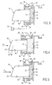
- FIG 3 shows another alternative embodiment of the invention constituting an active solution.
- the elements common with those of Figures 1 and 2 are designated by the same references.
- the impact element 10, which is also a projector, is held in the mounting block 14 by frangible means 30 by trapping the compressible member 16 in a compressed state, and not in an uncompressed state. as in the previous embodiment.
- frangible means 10 are also constituted by fastening lugs having a rupture zone 32 (FIG. 4).
- these break zones are here controlled trigger, that is to say that they can be broken voluntarily through an appropriate trigger signal. They are therefore distinguished from the rupture zones 28 of the tabs 26 of the previous embodiment which, they are broken under the action of a shock.
- the detection of a shock is carried out by a suitable sensor. 34, for example of the radar type, placed in a chosen location from the front.
- This appropriate sensor which is not directly part of the object of the invention, is capable of detecting a risk of collision and of sending a signal S to deliberately trigger a rupture of the rupture zones 32 of the tabs 30.
- the tabs break, causing a forward movement (arrow F2) of the projector 10 under the effect of decompression of the foam, a distance x, for example of the order of 20 mm.
- This forward movement is also favored by the presence of a leaf spring 36 which is interposed between the two ends 38 and 40 of the fixing lug 30.
- the projector 10 can move back with respect to the front face.provoking the compression of the compressible member 16 and the deformation of the two springs 36 which are at again in the curved state.
- FIG. 6 shows in detail a fastening lug 30 which is associated with a spring blade 36.
- the fastening lug 30 has a rupture zone 32 controlled trigger, here constituted by an explosive cord.
- the latter may be constituted by a primer of the type used on air bags, also called "Airbag” (registered trademark) motor vehicles.
- the fixing lug 30 comprises two folded ends 38 and 40.
- the end 38 defines a notch 42 in which is engaged an end 44 of the spring blade.
- the end 40 of the bracket has a notch 46 in which is engaged an end 48 of the spring blade.
- the latter is also fixed on the plane of the tab by a fastener 50. As a result, after breaking the fastening tabs, the latter have their ends connected together via the spring blade as can be seen on Figure 4, thus preventing a detachment of the projector from the front face.
- FIG. 7 shows an example of a compressible block 16 of fairly complex shape, adapted to be housed in a mounting block and to receive an impact element 10, here a projector.
- the inner face 24 of the compressible member 16 is smooth.
- this internal face is provided with a multiplicity of protrusions 52 in the form of a truncated cone which are arranged to come into contact with the impact element 10 (here the housing 18 of the projector) and thus limit the contact area between the compressible member and the impact member. This makes it possible to dampen the shock gradually.
- the frustoconical projections 52 have an axis of revolution 54 which is substantially perpendicular to the inner surface 24 of the compressible member 16.
- Each of the projections 52 includes a large base 56 attached to the inner face 24 of the compressible member and a small base 58 clean to come into contact with the impact member 10, here with the housing 18 of a projector.
- the small base preferably has a diameter B of 10 to 20 mm, the large base a diameter A of about 2.5 times the diameter B, and a height C of 10 to 30 mm.
- the compressible member 16 has a thickness D of 10 to 100 mm.
- FIG. 10 is similar to FIG. 8. It shows the same compressible member 16 which receives the projector 10.
- FIG. 11 closely resembles that of FIG. 8.
- the main difference here lies in the fact that the protrusions 52, which are also cone-shaped, each have their axis inclined relative to the internal face 24, the inclination being for example 45 degrees.
- the invention is of course applied to the protection of shocks vis-à-vis other impact elements of the front face, whether apparent or hidden elements.
Claims (16)
- Schutzvorrichtung gegen die Stöße mit einem Stoßelement (10) einer Vorderfront eines Kraftfahrzeugs, einem Montageblock (14) und einem komprimierbaren Element (16), dadurch gekennzeichnet, dass das Stoßelement (10) in dem Montageblock (14), der Teil der Vorderfront ist, mit Hilfe des komprimierbaren Elements (16) gehalten wird, das eine Vorderseite (22), die in dem Montageblock (14) aufgenommen wird, und eine Innenseite (24) aufweist, die derart ausgebildet ist, dass sie das Stoßelement (10) aufnimmt.
- Vorrichtung nach Anspruch 1, dadurch gekennzeichnet, dass die Innenseite (24) des komprimierbaren Elements (16) mit einer Vielzahl von Vorsprüngen (52) versehen ist, die derart angeordnet sind, dass sie mit dem Stoßelement (10) in Kontakt kommen und so die Kontaktfläche zwischen dem komprimierbaren Element (16) und dem Stoßelement (10) begrenzen.
- Vorrichtung nach Anspruch 2, dadurch gekennzeichnet, dass die Vorsprünge (52) jeweils im Wesentlichen die Form eines Kegelstumpfes haben, der eine große Basis (56), die mit der Innenseite (24) des komprimierbaren Elements (16) verbunden ist, und eine kleine Basis (58) aufweist, die mit dem Stoßelement (10) in Kontakt kommen kann, wobei sich eine Umdrehungsachse (54) mit gewählter Ausrichtung ergibt.
- Vorrichtung nach Anspruch 3, dadurch gekennzeichnet, dass die Umdrehungsachse (54) des Vorsprungs (52) in Form eines Kegelstumpfes im Wesentlichen senkrecht zu der Innenfläche (24) des komprimierbaren Elements (16) steht.
- Vorrichtung nach Anspruch 3, dadurch gekennzeichnet, dass die Umdrehungsachse (54) des Vorsprungs (52) in Form eines Kegelstumpfes in Bezug auf die Innenseite (24) des komprimierbaren Elements (16) geneigt ist.
- Vorrichtung nach einem der Ansprüche 3 bis 5, dadurch gekennzeichnet, dass der Vorsprung (52) in Form eines Kegelstumpfes eine kleine Basis (58) mit einem Durchmesser (B) von 10 bis 20 mm, eine große Basis (56) mit einem Durchmesser (A) von ungefähr 2,5 Mal dem Durchmesser der kleinen Basis und eine Höhe (C) von 10 bis 30 mm umfasst und dass das komprimierbare Element (16) im Bereich des Vorsprungs eine Dicke (D) von 10 bis 100 mm besitzt.
- Vorrichtung nach einem der Ansprüche 1 bis 6, dadurch gekennzeichnet, dass das komprimierbare Element (16) von einem Schaumblock aus einem Material gebildet ist, das ausgewählt wird unter den Kunststoffen des Typs Thermoplast, Kautschuk, Zellstoff oder Elastomer, und eine Tragfähigkeit zwischen 0,15 und 1,5 Mpa besitzt.
- Vorrichtung nach einem der Ansprüche 1 bis 7, dadurch gekennzeichnet, dass das Stoßelement (10) in dem Montageblock (14) mit Hilfe von Bruchmitteln (26) gehalten wird, wobei das komprimierbare Element (16) in einem nicht komprimierten Zustand eingeschlossen ist, so dass sich im Falle eines Aufpralls das Stoßelement (10) in den Montageblock (14) zurückzieht, wobei es einen Bruch der Bruchmittel (26) und eine Kompression des komprimierbaren Elements (16) hervorruft.
- Vorrichtung, nach Anspruch 8, dadurch gekennzeichnet, dass die Bruchmittel mindestens ein Stück (26) umfassen, das eine Schwächungszone (28) aufweist.
- Vorrichtung nach einem der Ansprüche 1 bis 7, dadurch gekennzeichnet, dass das Stoßelement (10) in dem Montageblock (14) mit Hilfe von Bruchmitteln (30) gehalten wird, wobei das komprimierbare Element (16) in einem komprimierten Zustand eingeschlossen ist, so dass im Falle einer Erfassung eines Aufpralls die Bruchmittel (30) zerbrochen werden, wobei somit eine Dekompression des komprimierbaren Elements (16) und eine Verschiebung des Stoßelements (10) nach vorne hervorgerufen werden, wobei das Element sich dann unter der Wirkung eines Aufpralls nach hinten schieben kann.
- Vorrichtung nach Anspruch 10, dadurch gekennzeichnet, dass die Bruchmittel mindestens ein Stück (30) umfassen, das eine Bruchzone (32) mit kontrollierter Auslösung aufweist.
- Vorrichtung nach Anspruch 11, dadurch gekennzeichnet, dass die Bruchzone (32) mit kontrollierter Auslösung eine Zündschnur ist.
- Vorrichtung nach einem der Ansprüche 10 bis 12, dadurch gekennzeichnet, dass sie ferner Federmittel (36) umfasst, die zwischen dem Stoßelement (10) und dem Montageblock (14) angeordnet und derart vorgesehen sind, dass sie das Stoßelement (10) beim Brechen der Bruchmittel (30) nach vorne schieben.
- Vorrichtung nach Anspruch 13, dadurch gekennzeichnet, dass die Federmittel mindestens eine Blattfeder (36) umfassen.
- Vorrichtung nach einem der Ansprüche 1 bis 14, dadurch gekennzeichnet, dass das Stoßelement (10) ein Projektor ist.
- Vorrichtung nach Anspruch 15, dadurch gekennzeichnet, dass der Montageblock, der Teil der Vorderseite ist, das Gehäuse des Projektors ist.
Priority Applications (1)
| Application Number | Priority Date | Filing Date | Title |
|---|---|---|---|
| PL04719484T PL1601558T3 (pl) | 2003-03-11 | 2004-03-11 | Urządzenie zabezpieczające przed zderzeniami dla przedniej strony samochodu |
Applications Claiming Priority (3)
| Application Number | Priority Date | Filing Date | Title |
|---|---|---|---|
| FR0303006A FR2852275B1 (fr) | 2003-03-11 | 2003-03-11 | Dispositif de protection contre les chocs pour une face avant de vehicule automobile |
| FR0303006 | 2003-03-11 | ||
| PCT/FR2004/000577 WO2004083008A1 (fr) | 2003-03-11 | 2004-03-11 | Dispositif de protection contre les chocs pour une face avant de vehicule automobile |
Publications (2)
| Publication Number | Publication Date |
|---|---|
| EP1601558A1 EP1601558A1 (de) | 2005-12-07 |
| EP1601558B1 true EP1601558B1 (de) | 2006-07-05 |
Family
ID=32893212
Family Applications (1)
| Application Number | Title | Priority Date | Filing Date |
|---|---|---|---|
| EP04719484A Expired - Lifetime EP1601558B1 (de) | 2003-03-11 | 2004-03-11 | Schutzvorrichtung gegen stösse für eine fahrzeugvorderseite |
Country Status (6)
| Country | Link |
|---|---|
| EP (1) | EP1601558B1 (de) |
| AT (1) | ATE332254T1 (de) |
| DE (1) | DE602004001456T2 (de) |
| FR (1) | FR2852275B1 (de) |
| PL (1) | PL1601558T3 (de) |
| WO (1) | WO2004083008A1 (de) |
Families Citing this family (9)
| Publication number | Priority date | Publication date | Assignee | Title |
|---|---|---|---|---|
| DE102005012760A1 (de) * | 2005-03-19 | 2006-09-21 | GM Global Technology Operations, Inc., Detroit | Kraftfahrzeugkarosserie |
| DE102005016457A1 (de) * | 2005-04-11 | 2006-10-26 | GM Global Technology Operations, Inc., Detroit | Kraftfahrzeug mit in einer Normalposition kräftefreien und erst in einer Crashposition eine Haltewirkung ausübenden Haltevorrichtung für einen Scheinwerfer, sowie Scheinwerfer hierfür |
| FR2901202B1 (fr) * | 2006-05-22 | 2009-06-05 | Renault Sport Technologies Soc | Projecteur de vehicule automobile et vehicule automobile comportant un tel projecteur |
| FR2911824B1 (fr) * | 2007-01-31 | 2010-03-12 | Valeo Systemes Thermiques | Ensemble d'absorption de chocs pour projecteur de vehicule automobile |
| DE102007035279A1 (de) * | 2007-07-27 | 2009-01-29 | Audi Ag | Vorrichtung zur Anbringung eines Frontscheinwerfers an einer Karosserie |
| JP5720895B2 (ja) * | 2011-10-04 | 2015-05-20 | 三菱自動車工業株式会社 | 自動車用のヘッドランプ装置 |
| FR3046759B1 (fr) * | 2016-01-15 | 2018-01-26 | Psa Automobiles Sa. | Projecteur avec patte de fixation frangible et guidee |
| DE102019102892A1 (de) * | 2019-02-06 | 2020-08-06 | Dr. Ing. H.C. F. Porsche Aktiengesellschaft | Kraftfahrzeugscheinwerfer |
| DE102021114257A1 (de) | 2021-06-02 | 2022-12-29 | Bayerische Motoren Werke Aktiengesellschaft | Funktionsmodul für zumindest eine Licht- und/oder Sensorfunktion in einem Kraftfahrzeug |
Family Cites Families (6)
| Publication number | Priority date | Publication date | Assignee | Title |
|---|---|---|---|---|
| DE2542920C3 (de) * | 1975-09-26 | 1979-10-25 | Dr.Ing.H.C. F. Porsche Ag, 7000 Stuttgart | Stoßfänger für Fahrzeuge, insbesondere Kraftfahrzeuge |
| AT362240B (de) * | 1977-12-30 | 1981-04-27 | Steyr Daimler Puch Ag | Schutzvorrichtung fuer kraftfahrzeuge |
| GB2321624A (en) * | 1997-01-27 | 1998-08-05 | Lin Pac Mouldings | Bumper assembly with forwardly displaceable lower portion |
| DE19853340A1 (de) * | 1998-11-19 | 2000-05-25 | Volkswagen Ag | Sicherheitseinrichtung als Fußgängeraufprallschutz am Vorderwagen eines Kraftfahrzeugs |
| DE69900059T2 (de) * | 1999-04-24 | 2001-08-02 | Ford Global Tech Inc | Scheinwerfer mit Fussgängerschutzeinrichtung |
| DE10037051A1 (de) * | 2000-07-29 | 2002-02-28 | Acts Gmbh & Co Kg | Kraftfahrzeug und Stoßfängeranordnung für ein Kraftfahrzeug |
-
2003
- 2003-03-11 FR FR0303006A patent/FR2852275B1/fr not_active Expired - Fee Related
-
2004
- 2004-03-11 PL PL04719484T patent/PL1601558T3/pl unknown
- 2004-03-11 DE DE602004001456T patent/DE602004001456T2/de not_active Expired - Lifetime
- 2004-03-11 WO PCT/FR2004/000577 patent/WO2004083008A1/fr active IP Right Grant
- 2004-03-11 AT AT04719484T patent/ATE332254T1/de not_active IP Right Cessation
- 2004-03-11 EP EP04719484A patent/EP1601558B1/de not_active Expired - Lifetime
Also Published As
| Publication number | Publication date |
|---|---|
| PL1601558T3 (pl) | 2006-11-30 |
| FR2852275A1 (fr) | 2004-09-17 |
| DE602004001456D1 (de) | 2006-08-17 |
| FR2852275B1 (fr) | 2005-06-10 |
| ATE332254T1 (de) | 2006-07-15 |
| DE602004001456T2 (de) | 2007-02-15 |
| WO2004083008A1 (fr) | 2004-09-30 |
| EP1601558A1 (de) | 2005-12-07 |
Similar Documents
| Publication | Publication Date | Title |
|---|---|---|
| EP1514768B1 (de) | Gebrauchsverfahren fur einem Kotflügel und eine Motorhaube, mit einem Luftkissen und einem Kotflügel Stutz , Kfz-Kotflügel, Kfz-Kotflügelmodul, und Kfz-Motorhaube | |
| EP1747125B1 (de) | Stützelement für ein autoteil | |
| EP1957313B1 (de) | Kraftfahrzeugteil mit mitteln zum stützen eines optischen blocks | |
| EP1601558B1 (de) | Schutzvorrichtung gegen stösse für eine fahrzeugvorderseite | |
| EP1422110B1 (de) | Autostossfänger mit einem komprimierbarem Block der einen zunehmenden Querschnitt hat | |
| EP3732080B1 (de) | Frontaufprallabsorptonsvorrichtung für kraftfahrzeug mit einem schwenkbaren luftablenker und einem verformbaren aufprallabsorber, die miteinander verbunden sind | |
| EP2531382B1 (de) | Einheit mit einer aktiven motorhaube für den fussgängerschutz und damit ausgerüstetes fahrzeug | |
| FR2921611A1 (fr) | Dispositif de securite a sac gonflable pour vehicule automobile | |
| FR2927865A1 (fr) | Dispositif d'absorption de choc avec absorbeurs superieur et interieur relies par un element de liaison deformable | |
| FR2937925A1 (fr) | Systeme de protection des passagers d'un vehicule en cas de capotage, munit d'un dispositif de fixation perfectionne | |
| FR2852564A1 (fr) | Dispositif de protection contre les chocs pour une face avant de vehicule automobile | |
| EP1817212A1 (de) | Aufprallschutzvorrichtung für die vorderwand eines kraftfahrzeugs und die vorrichtung umfassende vorderwand | |
| EP2969705A1 (de) | Kraftfahrzeug mit mittel zur positionierung einer zusammenschiebbaren lenksäule | |
| EP3898304B1 (de) | Kraftfahrzeug mit einem motorträger und einem fahrgestell | |
| EP1400406B1 (de) | Kfz-Scheinwerfer mit verformbaren Mitteln zur Absorption mindestens eines Teils der Energie bei einem Aufprall | |
| FR2792894A1 (fr) | Dispositif de retenue de charges dans le coffre d'un vehicule automobile | |
| EP2424751B1 (de) | Hekklapperaum und eine heckklappe mit sicherheitsanordnungen | |
| WO2020174161A1 (fr) | Sous-ensemble de structure de pare-chocs comprenant un element amortisseur associe a un capteur d'impact | |
| FR2818706A1 (fr) | Dispositif de fixation securise pour la fixation d'accessoires sur un vehicule | |
| EP1669262B1 (de) | Kraftfahrzeughaube mittels Dämpfern | |
| FR2944753A1 (fr) | Ensemble haut-parleur avec son support pour vehicule automobile permettant la protection de l'element du vehicule le recevant en cas de choc sur celui-ci. | |
| FR2898847A1 (fr) | Dispositif d'absorption d'energie pour partie avant de vehicule automobile et partie avant de vehicule automobile comportant ce dispositif | |
| FR2946586A1 (fr) | Dossier de siege pour vehicule. | |
| FR2913253A1 (fr) | Filtre a air muni de tirants pivotants. | |
| FR2912101A1 (fr) | Agencement d'un element mobile de protection contre les chocs deteriorants dans un bouclier de vehicule automobile |
Legal Events
| Date | Code | Title | Description |
|---|---|---|---|
| PUAI | Public reference made under article 153(3) epc to a published international application that has entered the european phase |
Free format text: ORIGINAL CODE: 0009012 |
|
| 17P | Request for examination filed |
Effective date: 20050823 |
|
| AK | Designated contracting states |
Kind code of ref document: A1 Designated state(s): AT BE BG CH CY CZ DE DK EE ES FI FR GB GR HU IE IT LI LU MC NL PL PT RO SE SI SK TR |
|
| AX | Request for extension of the european patent |
Extension state: AL LT LV MK |
|
| GRAP | Despatch of communication of intention to grant a patent |
Free format text: ORIGINAL CODE: EPIDOSNIGR1 |
|
| GRAS | Grant fee paid |
Free format text: ORIGINAL CODE: EPIDOSNIGR3 |
|
| GRAA | (expected) grant |
Free format text: ORIGINAL CODE: 0009210 |
|
| DAX | Request for extension of the european patent (deleted) | ||
| AK | Designated contracting states |
Kind code of ref document: B1 Designated state(s): AT BE BG CH CY CZ DE DK EE ES FI FR GB GR HU IE IT LI LU MC NL PL PT RO SE SI SK TR |
|
| PG25 | Lapsed in a contracting state [announced via postgrant information from national office to epo] |
Ref country code: IT Free format text: LAPSE BECAUSE OF FAILURE TO SUBMIT A TRANSLATION OF THE DESCRIPTION OR TO PAY THE FEE WITHIN THE PRESCRIBED TIME-LIMIT;WARNING: LAPSES OF ITALIAN PATENTS WITH EFFECTIVE DATE BEFORE 2007 MAY HAVE OCCURRED AT ANY TIME BEFORE 2007. THE CORRECT EFFECTIVE DATE MAY BE DIFFERENT FROM THE ONE RECORDED. Effective date: 20060705 Ref country code: AT Free format text: LAPSE BECAUSE OF FAILURE TO SUBMIT A TRANSLATION OF THE DESCRIPTION OR TO PAY THE FEE WITHIN THE PRESCRIBED TIME-LIMIT Effective date: 20060705 Ref country code: IE Free format text: LAPSE BECAUSE OF FAILURE TO SUBMIT A TRANSLATION OF THE DESCRIPTION OR TO PAY THE FEE WITHIN THE PRESCRIBED TIME-LIMIT Effective date: 20060705 Ref country code: SK Free format text: LAPSE BECAUSE OF FAILURE TO SUBMIT A TRANSLATION OF THE DESCRIPTION OR TO PAY THE FEE WITHIN THE PRESCRIBED TIME-LIMIT Effective date: 20060705 Ref country code: NL Free format text: LAPSE BECAUSE OF FAILURE TO SUBMIT A TRANSLATION OF THE DESCRIPTION OR TO PAY THE FEE WITHIN THE PRESCRIBED TIME-LIMIT Effective date: 20060705 Ref country code: SI Free format text: LAPSE BECAUSE OF FAILURE TO SUBMIT A TRANSLATION OF THE DESCRIPTION OR TO PAY THE FEE WITHIN THE PRESCRIBED TIME-LIMIT Effective date: 20060705 Ref country code: RO Free format text: LAPSE BECAUSE OF FAILURE TO SUBMIT A TRANSLATION OF THE DESCRIPTION OR TO PAY THE FEE WITHIN THE PRESCRIBED TIME-LIMIT Effective date: 20060705 Ref country code: CZ Free format text: LAPSE BECAUSE OF FAILURE TO SUBMIT A TRANSLATION OF THE DESCRIPTION OR TO PAY THE FEE WITHIN THE PRESCRIBED TIME-LIMIT Effective date: 20060705 Ref country code: FI Free format text: LAPSE BECAUSE OF FAILURE TO SUBMIT A TRANSLATION OF THE DESCRIPTION OR TO PAY THE FEE WITHIN THE PRESCRIBED TIME-LIMIT Effective date: 20060705 Ref country code: GB Free format text: LAPSE BECAUSE OF FAILURE TO SUBMIT A TRANSLATION OF THE DESCRIPTION OR TO PAY THE FEE WITHIN THE PRESCRIBED TIME-LIMIT Effective date: 20060705 |
|
| REG | Reference to a national code |
Ref country code: GB Ref legal event code: FG4D Free format text: NOT ENGLISH |
|
| REG | Reference to a national code |
Ref country code: CH Ref legal event code: EP |
|
| REG | Reference to a national code |
Ref country code: IE Ref legal event code: FG4D Free format text: LANGUAGE OF EP DOCUMENT: FRENCH |
|
| REF | Corresponds to: |
Ref document number: 602004001456 Country of ref document: DE Date of ref document: 20060817 Kind code of ref document: P |
|
| PG25 | Lapsed in a contracting state [announced via postgrant information from national office to epo] |
Ref country code: DK Free format text: LAPSE BECAUSE OF FAILURE TO SUBMIT A TRANSLATION OF THE DESCRIPTION OR TO PAY THE FEE WITHIN THE PRESCRIBED TIME-LIMIT Effective date: 20061005 Ref country code: SE Free format text: LAPSE BECAUSE OF FAILURE TO SUBMIT A TRANSLATION OF THE DESCRIPTION OR TO PAY THE FEE WITHIN THE PRESCRIBED TIME-LIMIT Effective date: 20061005 Ref country code: BG Free format text: LAPSE BECAUSE OF FAILURE TO SUBMIT A TRANSLATION OF THE DESCRIPTION OR TO PAY THE FEE WITHIN THE PRESCRIBED TIME-LIMIT Effective date: 20061005 |
|
| PG25 | Lapsed in a contracting state [announced via postgrant information from national office to epo] |
Ref country code: ES Free format text: LAPSE BECAUSE OF FAILURE TO SUBMIT A TRANSLATION OF THE DESCRIPTION OR TO PAY THE FEE WITHIN THE PRESCRIBED TIME-LIMIT Effective date: 20061016 |
|
| NLV1 | Nl: lapsed or annulled due to failure to fulfill the requirements of art. 29p and 29m of the patents act | ||
| PG25 | Lapsed in a contracting state [announced via postgrant information from national office to epo] |
Ref country code: PT Free format text: LAPSE BECAUSE OF FAILURE TO SUBMIT A TRANSLATION OF THE DESCRIPTION OR TO PAY THE FEE WITHIN THE PRESCRIBED TIME-LIMIT Effective date: 20061205 |
|
| GBV | Gb: ep patent (uk) treated as always having been void in accordance with gb section 77(7)/1977 [no translation filed] |
Effective date: 20060705 |
|
| REG | Reference to a national code |
Ref country code: IE Ref legal event code: FD4D |
|
| PLBE | No opposition filed within time limit |
Free format text: ORIGINAL CODE: 0009261 |
|
| STAA | Information on the status of an ep patent application or granted ep patent |
Free format text: STATUS: NO OPPOSITION FILED WITHIN TIME LIMIT |
|
| 26N | No opposition filed |
Effective date: 20070410 |
|
| BERE | Be: lapsed |
Owner name: VALEO THERMIQUE MOTEUR Effective date: 20070331 |
|
| PG25 | Lapsed in a contracting state [announced via postgrant information from national office to epo] |
Ref country code: BE Free format text: LAPSE BECAUSE OF NON-PAYMENT OF DUE FEES Effective date: 20070331 |
|
| PG25 | Lapsed in a contracting state [announced via postgrant information from national office to epo] |
Ref country code: MC Free format text: LAPSE BECAUSE OF NON-PAYMENT OF DUE FEES Effective date: 20070331 |
|
| PG25 | Lapsed in a contracting state [announced via postgrant information from national office to epo] |
Ref country code: GR Free format text: LAPSE BECAUSE OF FAILURE TO SUBMIT A TRANSLATION OF THE DESCRIPTION OR TO PAY THE FEE WITHIN THE PRESCRIBED TIME-LIMIT Effective date: 20061006 |
|
| PG25 | Lapsed in a contracting state [announced via postgrant information from national office to epo] |
Ref country code: EE Free format text: LAPSE BECAUSE OF FAILURE TO SUBMIT A TRANSLATION OF THE DESCRIPTION OR TO PAY THE FEE WITHIN THE PRESCRIBED TIME-LIMIT Effective date: 20060705 |
|
| REG | Reference to a national code |
Ref country code: CH Ref legal event code: PL |
|
| PG25 | Lapsed in a contracting state [announced via postgrant information from national office to epo] |
Ref country code: LI Free format text: LAPSE BECAUSE OF NON-PAYMENT OF DUE FEES Effective date: 20080331 Ref country code: CH Free format text: LAPSE BECAUSE OF NON-PAYMENT OF DUE FEES Effective date: 20080331 |
|
| PG25 | Lapsed in a contracting state [announced via postgrant information from national office to epo] |
Ref country code: CY Free format text: LAPSE BECAUSE OF FAILURE TO SUBMIT A TRANSLATION OF THE DESCRIPTION OR TO PAY THE FEE WITHIN THE PRESCRIBED TIME-LIMIT Effective date: 20060705 Ref country code: LU Free format text: LAPSE BECAUSE OF NON-PAYMENT OF DUE FEES Effective date: 20070311 |
|
| PG25 | Lapsed in a contracting state [announced via postgrant information from national office to epo] |
Ref country code: TR Free format text: LAPSE BECAUSE OF FAILURE TO SUBMIT A TRANSLATION OF THE DESCRIPTION OR TO PAY THE FEE WITHIN THE PRESCRIBED TIME-LIMIT Effective date: 20060705 Ref country code: HU Free format text: LAPSE BECAUSE OF FAILURE TO SUBMIT A TRANSLATION OF THE DESCRIPTION OR TO PAY THE FEE WITHIN THE PRESCRIBED TIME-LIMIT Effective date: 20070106 |
|
| PGFP | Annual fee paid to national office [announced via postgrant information from national office to epo] |
Ref country code: PL Payment date: 20150217 Year of fee payment: 12 |
|
| REG | Reference to a national code |
Ref country code: FR Ref legal event code: PLFP Year of fee payment: 13 |
|
| REG | Reference to a national code |
Ref country code: FR Ref legal event code: PLFP Year of fee payment: 14 |
|
| PG25 | Lapsed in a contracting state [announced via postgrant information from national office to epo] |
Ref country code: PL Free format text: LAPSE BECAUSE OF NON-PAYMENT OF DUE FEES Effective date: 20160311 |
|
| REG | Reference to a national code |
Ref country code: FR Ref legal event code: PLFP Year of fee payment: 15 |
|
| PGFP | Annual fee paid to national office [announced via postgrant information from national office to epo] |
Ref country code: DE Payment date: 20180309 Year of fee payment: 15 |
|
| PGFP | Annual fee paid to national office [announced via postgrant information from national office to epo] |
Ref country code: FR Payment date: 20180329 Year of fee payment: 15 |
|
| REG | Reference to a national code |
Ref country code: DE Ref legal event code: R119 Ref document number: 602004001456 Country of ref document: DE |
|
| PG25 | Lapsed in a contracting state [announced via postgrant information from national office to epo] |
Ref country code: DE Free format text: LAPSE BECAUSE OF NON-PAYMENT OF DUE FEES Effective date: 20191001 |
|
| PG25 | Lapsed in a contracting state [announced via postgrant information from national office to epo] |
Ref country code: FR Free format text: LAPSE BECAUSE OF NON-PAYMENT OF DUE FEES Effective date: 20190331 |