EP2329240B1 - Temperature sensor structure - Google Patents
Temperature sensor structure Download PDFInfo
- Publication number
- EP2329240B1 EP2329240B1 EP09782299.3A EP09782299A EP2329240B1 EP 2329240 B1 EP2329240 B1 EP 2329240B1 EP 09782299 A EP09782299 A EP 09782299A EP 2329240 B1 EP2329240 B1 EP 2329240B1
- Authority
- EP
- European Patent Office
- Prior art keywords
- material component
- contact surface
- thermal conductivity
- temperature
- temperature sensors
- Prior art date
- Legal status (The legal status is an assumption and is not a legal conclusion. Google has not performed a legal analysis and makes no representation as to the accuracy of the status listed.)
- Active
Links
Images
Classifications
-
- A—HUMAN NECESSITIES
- A61—MEDICAL OR VETERINARY SCIENCE; HYGIENE
- A61B—DIAGNOSIS; SURGERY; IDENTIFICATION
- A61B5/00—Measuring for diagnostic purposes; Identification of persons
- A61B5/01—Measuring temperature of body parts ; Diagnostic temperature sensing, e.g. for malignant or inflamed tissue
-
- G—PHYSICS
- G01—MEASURING; TESTING
- G01K—MEASURING TEMPERATURE; MEASURING QUANTITY OF HEAT; THERMALLY-SENSITIVE ELEMENTS NOT OTHERWISE PROVIDED FOR
- G01K1/00—Details of thermometers not specially adapted for particular types of thermometer
- G01K1/16—Special arrangements for conducting heat from the object to the sensitive element
- G01K1/165—Special arrangements for conducting heat from the object to the sensitive element for application in zero heat flux sensors
-
- G—PHYSICS
- G01—MEASURING; TESTING
- G01K—MEASURING TEMPERATURE; MEASURING QUANTITY OF HEAT; THERMALLY-SENSITIVE ELEMENTS NOT OTHERWISE PROVIDED FOR
- G01K1/00—Details of thermometers not specially adapted for particular types of thermometer
- G01K1/14—Supports; Fastening devices; Arrangements for mounting thermometers in particular locations
-
- G—PHYSICS
- G01—MEASURING; TESTING
- G01K—MEASURING TEMPERATURE; MEASURING QUANTITY OF HEAT; THERMALLY-SENSITIVE ELEMENTS NOT OTHERWISE PROVIDED FOR
- G01K1/00—Details of thermometers not specially adapted for particular types of thermometer
- G01K1/16—Special arrangements for conducting heat from the object to the sensitive element
-
- G—PHYSICS
- G01—MEASURING; TESTING
- G01K—MEASURING TEMPERATURE; MEASURING QUANTITY OF HEAT; THERMALLY-SENSITIVE ELEMENTS NOT OTHERWISE PROVIDED FOR
- G01K13/00—Thermometers specially adapted for specific purposes
- G01K13/20—Clinical contact thermometers for use with humans or animals
-
- G—PHYSICS
- G01—MEASURING; TESTING
- G01K—MEASURING TEMPERATURE; MEASURING QUANTITY OF HEAT; THERMALLY-SENSITIVE ELEMENTS NOT OTHERWISE PROVIDED FOR
- G01K7/00—Measuring temperature based on the use of electric or magnetic elements directly sensitive to heat ; Power supply therefor, e.g. using thermoelectric elements
- G01K7/42—Circuits effecting compensation of thermal inertia; Circuits for predicting the stationary value of a temperature
-
- A—HUMAN NECESSITIES
- A61—MEDICAL OR VETERINARY SCIENCE; HYGIENE
- A61B—DIAGNOSIS; SURGERY; IDENTIFICATION
- A61B2562/00—Details of sensors; Constructional details of sensor housings or probes; Accessories for sensors
- A61B2562/02—Details of sensors specially adapted for in-vivo measurements
- A61B2562/0271—Thermal or temperature sensors
-
- A—HUMAN NECESSITIES
- A61—MEDICAL OR VETERINARY SCIENCE; HYGIENE
- A61B—DIAGNOSIS; SURGERY; IDENTIFICATION
- A61B2562/00—Details of sensors; Constructional details of sensor housings or probes; Accessories for sensors
- A61B2562/04—Arrangements of multiple sensors of the same type
- A61B2562/043—Arrangements of multiple sensors of the same type in a linear array
Definitions
- This invention relates to a device for measuring temperature, particularly the temperature of an animal or human body.
- Sensors for measuring temperature are well known and include thermistors, thermocouples and semiconductor-based electronic sensors. If correctly calibrated, such sensors can provide an indication of the temperature of an object in the region from which the sensor takes its inputs. For example, a thermistor placed in direct contact with an object will give an indication of the temperature of that part of the object with which the sensor is in contact.
- an object does not have a uniform temperature and its measured temperature varies throughout its volume.
- the temperature of an animal or human typically varies from its core body temperature to skin temperature.
- Skin temperature can vary considerably with environmental conditions and it is therefore the core body temperature which is typically more important for medical and diagnostic applications.
- US Patent Application No. 2007/0282218 discloses a device for measuring the local temperature of an external surface of a body using at least two temperature sensors separated by an insulating layer. The measurements may be used to calculate core body temperature by correcting for a difference between core body temperature and local temperature. Algorithms for performing such a correction in dependence on known thermal characteristics of the body are well known in the art (for example, see “ Computation of mean body temperature from rectal and skin temperatures", Journal Applied Physiology 31: 484-489, 1971 ).
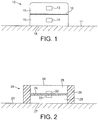
- FIG. 1 An example of a conventional device 12 for measuring the temperature of a body 11 is shown in figure 1 .
- Temperature sensors 13 and 14 are arranged at different distances from the external surface 18 of body 11 in material 15, and are separated by a thermally-insulating barrier 16. The effect of thermally-insulating barrier 16 is to cause temperature sensors 13 and 14 to attain different equilibrium temperatures at different rates, such that a measurement of the temperature of body 11 can be estimated from the heat flow across the device between the first and second sensors.
- US 2007/0295713 describes a system for measuring core body temperature by means of a skin thermometer comprising two or more layers of insulated temperature sensors.
- a thermal insulation component surrounds the sensor on all sides except the side of the sensor in contact with the skin.
- the insulation component has sufficient thickness at the sides of the sensor so that there is substantially negligible thermal contact with the environment of the thermometer.
- US 2008/170600 A1 describes a system for measuring core body temperature by means of a skin thermometer comprising two vertically stacked temperature sensors contained within a block of insulating material. An additional layer surrounding the sensor block in the radial direction is used for lateral insulation.
- a device for measuring temperature comprising: first and second temperature sensors enclosed in a material comprising a first material component and a second material component, the first and second temperature sensors being embedded in the first material component and the second material component at least partially enclosing the first material component and having a lower thermal conductivity than the first material component; and a contact surface for contacting a body whose temperature is to be measured; wherein the first and second temperature sensors are arranged at different depths from the contact surface and the net thermal conductivity across the device from the contact surface through the first and second temperature sensors is greater than the net thermal conductivity of the device in lateral directions parallel to the contact surface; wherein the first and second temperature sensors are mounted on a circuit board which extends substantially across the first material component between the first and second temperature sensors, the circuit board and first material component having substantially the same thermal conductivity of at least 0.5 W/mK.
- the first material component has a greater thermal conductivity than the second material component by a factor of at least 4.
- the second material component may completely enclose the first material component.
- the second material component is thicker over the lateral extremities of the first material component than over the contact surface and its opposing surface.
- the first material component is substantially disc-shaped, the plane of the disc being substantially parallel to the contact surface.
- the second material component forms a ring-shaped annulus about the disc-shaped first material component, the plane of the ring being substantially coincident with the plane of the disc.
- Each depth may be a distance from the contact surface to the respective temperature sensor along an axis substantially perpendicular to the contact surface.
- each depth is a thermal depth defined by the net thermal conductance from the contact surface to the respective temperature sensor.
- a surface of the first material component provides at least part of said contact surface.
- the first material component comprises at least first and second parts having different thermal conductivities, the first temperature sensor being embedded in the first part and the second temperature sensor being embedded in the second part.
- the first temperature sensor being embedded in the first part
- the second temperature sensor being embedded in the second part.
- at least part of the contact surface is provided by the first and second parts.
- the net thermal conductivity across the device is lowest in the lateral directions.
- a surface of the first material component remote from said contact surface is exposed.
- said remote surface supports a thin layer having a higher thermal conductivity than the first material component.
- the first material component has a thermal conductivity of 3 W/mK.
- the first material component has a greater thermal conductivity than the second material component by a factor of at least 10.
- the present invention provides an improved device for measuring temperature and heat flow into or out of a subject body.
- the device is particularly suitable for measuring the temperature of a human or animal body.
- a measure of the heat flow from a body combined with a measure of the temperature at the surface of that body allows the calculation of an estimate of a temperature within the body, if one knows something of the thermal characteristics of the body.
- the core body temperature (Tcore) of a human or animal may be estimated from a first temperature T1 taken at a first point (such as at the skin) and a second temperature T2 measured at a second point related to the first point by a known thermal transfer function.
- Tcore T 1 + A . T 2 ⁇ T 1
- Parameter A is typically an empirically determined coefficient which depends upon the thermal characteristics of the device (the thermal transfer function) and the body tissue. Including higher order terms can further improve the accuracy of this estimate.
- the thermal characteristics of the device can be straightforwardly selected by design and measured precisely in the laboratory.
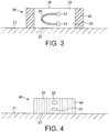
- FIG. 2 shows a device 28 in accordance with a first aspect of the present invention.
- Temperature sensors 22 and 23 are mounted on PCB 24, which may or may not extend across the diameter of material component 25 in which it is embedded.
- PCB 24 is chosen to have a similar thermal conductivity to material 25 such that the effect of its presence on the flow of heat to the first and second temperature sensors 22, 23 is minimised. Indeed, PCB 24 may be omitted if there is some other means of connection to the sensors, in which case material 25 extends between sensors 22 and 23.
- Material 25 is partially enclosed by material 26, which has a lower thermal conductivity than material 25.
- Device 28 is configured such that material 25 provides a contact surface 27 that is adapted to contact the body whose temperature is to be measured (such as the skin of a human).
- Surface 27 will be referred to herein as the contact surface, and the opposing surface of a device in accordance with the present invention, out of which heat from the body flows, will be referred to as the outer surface.
- Surface 27 may support an adhesive or other means for attaching the device to the surface of a subject body.
- sensors 22 and 23 are situated at different distances from contact surface 27 such that the sensors are at different distances from body 21 (the source of heat).
- sensors 22 and 23 lie on a common axis perpendicular to contact surface 27. This configuration assumes that the vector describing the heat gradient close to the surface of body 21 is normal to that surface.
- material 26 does not extend completely over the contact or outer surfaces of the device. It is advantageous if a surface of material 25 forms at least part of contact surface 27 such that the material contacts body 21 in use, and that a surface of material 25 forms at least part of outer surface 29 such that the material is exposed to the environment, allowing heat to flow through the device and out of that surface.
- Material 26 may enclose material 25 completely, but in this embodiment, it is preferably that material 26 is thinner over the outer and/or contact surface, or be doped in those regions with a more conductive material (such as a metal) so as to increase its conductivity.
- One or both of the contact and outer surfaces may support a thin layer (typically less than 1 mm thick) of an additional material (not shown in the figures).
- This additional material may have a high thermal conductivity (for example, greater than that of material 25 and preferably at least 10 W/mK) so as to efficiently couple (a) the contact surface to the body whose temperature is being measured, and/or (b) the outer surface to the ambient environment.
- the additional material may be sufficiently thin (preferably less than 0.25 mm), it may have a low thermal conductivity (possibly lower than 1 W/mK) and act as a protective layer for the respective surface, or means for supporting (for example) an adhesive layer.
- the rates at which the sensors reach their equilibrium temperatures can be varied. It is envisaged that the extent to which the insulating material extends over the outer surface is selected empirically, taking into account the typical range of temperatures expected of the body and environment.
- the arrangement of material components 25 and 26 is chosen such that an axis of greatest thermal conductivity across the device is defined.
- the axis of greatest thermal conductivity is roughly perpendicular to contact surface 27, through material 25. This is because material 26, which has a lower thermal conductivity, reduces the net thermal conductivity in the directions parallel to contact surface 27 (i.e. laterally).
- the axis of greatest thermal conductivity is preferably coincident with the direction of heat flow out of body 21.
- the direction of the vector describing the flow of heat from body 21 is chosen to be coincident with the direction of highest thermal conductivity of the device when the device is placed in position on the body.
- the arrangement of the present invention helps to minimise the leakage of heat to the sensors from the lateral extremities of the device and ensure that it is the heat flow from the core of the body that is measured.
- the thermal conductivity of material 26 is at least 4 times smaller than that of material 25, and preferably at least 10 times smaller.
- Material 25 preferably has a thermal conductivity of at least 0.5 W/mK. It is particularly advantageous if material 25 is a thermoconductive polymer, such as D8102 manufactured by Cool Polymers which has a thermal conductivity of 3 W/mK.
- Material 26 is preferably a thermoplastic, such as polyvinyl chloride (PVC) or polyurethane (PU).
- material 25 is substantially disc-shaped having greater extent parallel to surface 27 than normal to surface 27.
- an appropriate diameter for a patch for the human body is approximately 15 mm, with the two parts of material 25 being approximately 2.5 mm and separated by a PCB disc also 15 mm in diameter and 1 mm thick.
- material 26 forms a ring-shaped annulus about material 25, and in the present example is preferably a coating approximately 1 mm thick over material 25.
- a device as shown in figure 2 may be conveniently manufactured by over-molding the temperature sensors with a thermally conductive polymer, and then over-molding the resulting article with a thermally insulating polymer predominantly in a ring laterally about the disc.
- the device may be constructed with a temperature sensor on each side of a printed circuit board.
- a first over-molding may then be performed using a polymer with thermal characteristics similar to or more conductive than those of the circuit board, and a second over-molding performed using a substantially more insulating polymer. If polymer 25 in which the PCB is embedded is particularly electrically conductive, a thin electrically-insulating layer or film may be employed between the PCB and the conductive polymer.
- Figure 3 shows a second embodiment of the present invention in which sensors 22, 23 are mounted on a flexible printed circuit board (PCB) 34.
- PCB printed circuit board
- Figure 4 shows a third embodiment of the present invention in which materials 25 and 26 of devices 28 and 38 are replaced by a single material 45 having an anisotropic thermal conductivity.
- Material 45 may comprise multiple material components arranged so as to provide the anisotropic thermal conductivity.
- Sensors 22 and 23 are arranged in material 45 so as to lie substantially along the axis of greatest thermal conductivity of the material and device (indicated by the dashed lines in figure 4 ). Since it is typically desired to capture the flow of heat in a normal direction out of body 21, the axis of greatest thermal conductivity of material 45 will generally be substantially perpendicular to contact surface 27 of device 48.
- the axis of lowest thermal conductivity of material 45 is substantially perpendicular to the axis of greatest thermal conductivity so as to minimise the leakage of heat to the sensors from the lateral portions of the device.
- Suitable materials having anisotropic thermal conductivity include thermally conductive polymers having substantially aligned polymer chains and a material matrix of electrically conductive components (such as metal fibres) aligned in a polymeric insulating base material.
- material 45 is selected so as to have an anisotropy ratio of at least 2: i.e. the thermal conductivity along the axis of greatest thermal conductivity is at least twice that along a substantially perpendicular axis of lowest thermal conductivity. Most preferably the anisotropy ratio is at least 5. Further advantageously, the thermal conductivity in all directions perpendicular to the axis of greatest thermal conductivity is substantially the same (preferably within 20%).
- Contact surface 27 need not be perfectly flat and preferably is adapted to conform to the external surface of the body whose temperature is to be measured. If body 21 is a human or animal body, it is advantageous if a device in accordance with the present invention is flexible so as to allow the contact surface to maintain a good contact with body 21 during movements of the human or animal.
- the temperature sensors are at different depths from the contact surface so that each sensor reaches a different equilibrium temperature (as required by the above equation for estimating the core temperature of a body).
- This depth may be the perpendicular distance from the contact surface to the subject temperature sensor.
- the depth may be defined by the "thermal depth" of the temperature sensor from the contact surface.
- the thermal depth is the net thermal conductance of the device from the contact surface to the subject temperature sensor and varies with both the distance of the temperature sensor from the contact surface and the thermal conductivity of the intervening material(s).
- each temperature sensor By arranging for the thermal conductance from the contact surface to be different for each temperature sensor, each temperature sensor will equilibrate at a different temperature.
- material 25 comprises a first material component in which a first temperature sensor is enclosed and a second material component in which a second temperature sensor is enclosed, the two material components having different thermal conductivities.
- material 25 can comprise two halves: a first half of the first material component containing the first temperature sensor and a second half of the second material component containing the second temperature sensor, with each material component extending between the respective temperature sensor and the contact surface.
- perpendicular distance shall be taken to mean the distance from the specified point to the specified surface along the line normal to that surface that passes through that point.
Landscapes
- Physics & Mathematics (AREA)
- General Physics & Mathematics (AREA)
- Health & Medical Sciences (AREA)
- Life Sciences & Earth Sciences (AREA)
- Biophysics (AREA)
- Pathology (AREA)
- Engineering & Computer Science (AREA)
- Biomedical Technology (AREA)
- Heart & Thoracic Surgery (AREA)
- Medical Informatics (AREA)
- Molecular Biology (AREA)
- Surgery (AREA)
- Animal Behavior & Ethology (AREA)
- General Health & Medical Sciences (AREA)
- Public Health (AREA)
- Veterinary Medicine (AREA)
- Measuring And Recording Apparatus For Diagnosis (AREA)
- Measuring Temperature Or Quantity Of Heat (AREA)
- Investigating Or Analyzing Materials Using Thermal Means (AREA)
Applications Claiming Priority (2)
| Application Number | Priority Date | Filing Date | Title |
|---|---|---|---|
| GBGB0815694.5A GB0815694D0 (en) | 2008-08-28 | 2008-08-28 | Tempreature sensor structure |
| PCT/EP2009/061096 WO2010023255A1 (en) | 2008-08-28 | 2009-08-27 | Temperature sensor structure |
Publications (2)
| Publication Number | Publication Date |
|---|---|
| EP2329240A1 EP2329240A1 (en) | 2011-06-08 |
| EP2329240B1 true EP2329240B1 (en) | 2017-09-13 |
Family
ID=39865895
Family Applications (1)
| Application Number | Title | Priority Date | Filing Date |
|---|---|---|---|
| EP09782299.3A Active EP2329240B1 (en) | 2008-08-28 | 2009-08-27 | Temperature sensor structure |
Country Status (9)
| Country | Link |
|---|---|
| US (2) | US9562811B2 (es) |
| EP (1) | EP2329240B1 (es) |
| JP (2) | JP5908280B2 (es) |
| CN (1) | CN102165296B (es) |
| BR (1) | BRPI0917713A2 (es) |
| GB (1) | GB0815694D0 (es) |
| MX (1) | MX2011002173A (es) |
| RU (1) | RU2489690C2 (es) |
| WO (1) | WO2010023255A1 (es) |
Cited By (1)
| Publication number | Priority date | Publication date | Assignee | Title |
|---|---|---|---|---|
| EP3850319B1 (de) * | 2018-11-09 | 2023-07-12 | Siemens Energy Global GmbH & Co. KG | Anordnung zum ermitteln der temperatur einer oberfläche |
Families Citing this family (35)
| Publication number | Priority date | Publication date | Assignee | Title |
|---|---|---|---|---|
| GB0617451D0 (es) | 2006-09-05 | 2006-10-18 | Medical Prediction Ltd | |
| US20120128468A1 (en) * | 2010-11-22 | 2012-05-24 | Kurt Kramer Schleif | Sensor assembly for use with a turbomachine and methods of assembling same |
| US10413251B2 (en) | 2012-10-07 | 2019-09-17 | Rhythm Diagnostic Systems, Inc. | Wearable cardiac monitor |
| US10244949B2 (en) * | 2012-10-07 | 2019-04-02 | Rhythm Diagnostic Systems, Inc. | Health monitoring systems and methods |
| DE13852079T1 (de) | 2012-11-01 | 2015-11-19 | Blue Spark Technologies, Inc. | Pflaster zur Protokollierung der Körpertemperatur |
| JP6337416B2 (ja) * | 2013-03-12 | 2018-06-06 | セイコーエプソン株式会社 | 温度測定装置 |
| DE102014002762A1 (de) | 2014-03-04 | 2015-09-10 | Storz Endoskop Produktions Gmbh | Messvorrichtung und Messverfahren zur Erfassung einer Umgebungstemperatur eines Geräts sowie Vorrichtung und Verfahren zur medizinischen Insufflation |
| JP6395176B2 (ja) * | 2014-03-07 | 2018-09-26 | 国立大学法人 奈良先端科学技術大学院大学 | 深部温度計 |
| DE102014006999A1 (de) | 2014-05-13 | 2015-11-19 | Swissmed Mobile Ag | Vorrichtung und Verfahren zur In-Vivo Erfassung von Patientendaten und Übertragung an eine Datenverarbeitungseinrichtung |
| JP2016057198A (ja) * | 2014-09-10 | 2016-04-21 | セイコーエプソン株式会社 | 熱流計測装置及び代謝計測装置 |
| JP6303973B2 (ja) * | 2014-10-20 | 2018-04-04 | 株式会社デンソー | 状態検出センサ |
| GB2533079B (en) * | 2014-10-28 | 2016-12-14 | Cambridge temperature concepts ltd | Battery thermal mass |
| US9483726B2 (en) | 2014-12-10 | 2016-11-01 | VivaLnk Inc. | Three dimensional electronic patch |
| US9693689B2 (en) | 2014-12-31 | 2017-07-04 | Blue Spark Technologies, Inc. | Body temperature logging patch |
| RU2580897C1 (ru) * | 2015-03-04 | 2016-04-10 | Государственное бюджетное образовательное учреждение высшего профессионального образования "Смоленская государственная медицинская академия" Министерства здравоохранения Российской Федерации | Устройство для измерения температуры тела человека |
| WO2016185905A1 (ja) * | 2015-05-15 | 2016-11-24 | 株式会社村田製作所 | 深部体温計 |
| EP3431946B1 (en) * | 2016-04-22 | 2021-03-31 | Murata Manufacturing Co., Ltd. | Deep body thermometer |
| JP7005513B2 (ja) | 2016-05-18 | 2022-01-21 | コーニンクレッカ フィリップス エヌ ヴェ | 単一熱流束センサ装置 |
| US20180008149A1 (en) * | 2016-07-06 | 2018-01-11 | General Electric Company | Systems and Methods of Body Temperature Measurement |
| US20180028069A1 (en) * | 2016-07-29 | 2018-02-01 | VivaLnk Inc. | Wearable thermometer patch for accurate measurement of human skin temperature |
| US10856741B2 (en) * | 2016-12-14 | 2020-12-08 | Vital Connect, Inc. | Core body temperature detection device |
| DE102017100267A1 (de) * | 2017-01-09 | 2018-07-12 | Endress + Hauser Wetzer Gmbh + Co. Kg | Thermometer |
| EP3639018A1 (en) | 2017-06-11 | 2020-04-22 | Epymetrics AG | Chip-based multi-channel electrochemical transducer and method of use thereof |
| DE102017116408A1 (de) | 2017-07-20 | 2019-01-24 | Endress + Hauser Wetzer Gmbh + Co. Kg | Thermisches Durchflussmessgerät |
| US10849501B2 (en) | 2017-08-09 | 2020-12-01 | Blue Spark Technologies, Inc. | Body temperature logging patch |
| DE102017120941A1 (de) * | 2017-09-11 | 2019-03-14 | Endress + Hauser Wetzer Gmbh + Co. Kg | Thermisches Durchflussmessgerät |
| CN110260911A (zh) * | 2018-03-12 | 2019-09-20 | 中国电力科学研究院有限公司 | 一种大截面导线弧垂在线监测系统 |
| DE102018204271A1 (de) | 2018-03-20 | 2019-09-26 | Te Connectivity Germany Gmbh | Anordnung zur Erfassung der Temperatur und Kontaktanordnung mit einer solchen Anordnung |
| US11903700B2 (en) | 2019-08-28 | 2024-02-20 | Rds | Vital signs monitoring systems and methods |
| DE102019134440A1 (de) | 2019-12-16 | 2021-06-17 | Endress + Hauser Wetzer Gmbh + Co. Kg | Messgerät |
| CN111693177A (zh) * | 2020-06-23 | 2020-09-22 | 广东小天才科技有限公司 | 体核温度测量方法、装置、介质和智能可穿戴设备 |
| TW202207867A (zh) * | 2020-08-24 | 2022-03-01 | 禾企電子股份有限公司 | 體溫異常個體快篩系統 |
| US11747213B2 (en) * | 2020-08-27 | 2023-09-05 | Unison Industries, Llc | Temperature sensor |
| US11766180B1 (en) * | 2020-12-07 | 2023-09-26 | Mark Newton | Identification of a true febrile state in humans through comparison of simultaneously measured core and peripheral temperatures |
| WO2023161998A1 (ja) * | 2022-02-22 | 2023-08-31 | 日本電信電話株式会社 | 温度測定装置 |
Citations (2)
| Publication number | Priority date | Publication date | Assignee | Title |
|---|---|---|---|---|
| EP1743571A2 (en) * | 2001-03-30 | 2007-01-17 | Bodymedia, Inc. | System for monitoring health, wellness and fitness having a method and apparatus for improved measurement of heat flow |
| US20080170600A1 (en) * | 2007-01-17 | 2008-07-17 | Dragerwerk Aktiegesellschaft | Double temperature sensor |
Family Cites Families (20)
| Publication number | Priority date | Publication date | Assignee | Title |
|---|---|---|---|---|
| US8017A (en) * | 1851-04-01 | Splint-machine | ||
| US7029A (en) * | 1850-01-15 | Winnowing-machike | ||
| JPS5221883A (en) * | 1975-08-12 | 1977-02-18 | Aichi Tokei Denki Co Ltd | Temperature measuring apparatus |
| JPS6358223A (ja) * | 1986-08-29 | 1988-03-14 | Tatsuo Togawa | 体温計測装置 |
| EP0325430B1 (en) * | 1988-01-18 | 1996-05-01 | Ishikawajima-Harima Heavy Industries Co., Ltd. | An apparatus for measuring thermal conductivity |
| FI96066C (fi) * | 1994-03-24 | 1996-04-25 | Polar Electro Oy | Menetelmä ja laite rakenteen sisälämpötilan ja sisäisen lämmönjohtavuuskertoimen määrittämiseksi |
| US6284078B1 (en) * | 1994-11-22 | 2001-09-04 | Medical Indicators, Inc. | Method for preparing an improved liquid crystal clinical thermometer |
| IL120758A (en) * | 1997-05-01 | 2000-02-29 | Medisim Ltd | High speed accurate temperature measuring device |
| US6220750B1 (en) * | 1999-03-29 | 2001-04-24 | Yoram Palti | Non-invasive temperature measurement method and apparatus |
| RU2155941C1 (ru) * | 1999-10-12 | 2000-09-10 | Блажис Анатолий Константинович | Термомонитор |
| GB0103886D0 (en) * | 2001-02-16 | 2001-04-04 | Baumbach Per L | Temperature measuring device |
| EP1249691A1 (en) * | 2001-04-11 | 2002-10-16 | Omron Corporation | Electronic clinical thermometer |
| JP4600170B2 (ja) * | 2004-09-15 | 2010-12-15 | セイコーエプソン株式会社 | 体温計、および体温計を有する電子機器 |
| DE102005004933B3 (de) * | 2005-02-03 | 2006-08-31 | Dräger Safety AG & Co. KGaA | Vorrichtung zur Messung der Körpertemperatur eines Lebewesens |
| DE102006012338B3 (de) * | 2006-03-17 | 2007-07-19 | Drägerwerk AG | Anordnung zum Messen der Kerntemperatur eines Körpers |
| US7597668B2 (en) | 2006-05-31 | 2009-10-06 | Medisim Ltd. | Non-invasive temperature measurement |
| US20070295713A1 (en) * | 2006-06-15 | 2007-12-27 | John Carlton-Foss | System and method for measuring core body temperature |
| JP4805773B2 (ja) * | 2006-09-20 | 2011-11-02 | シチズンホールディングス株式会社 | 電子温度計 |
| WO2008068665A1 (en) * | 2006-12-06 | 2008-06-12 | Koninklijke Philips Electronics, N.V. | Device for measuring core temperature |
| DE102008026642B4 (de) * | 2008-06-03 | 2010-06-10 | Dräger Medical AG & Co. KG | Doppeltemperatursensor mit einem Aufnahmeelement |
-
2008
- 2008-08-28 GB GBGB0815694.5A patent/GB0815694D0/en not_active Ceased
-
2009
- 2009-08-27 CN CN2009801380077A patent/CN102165296B/zh active Active
- 2009-08-27 BR BRPI0917713A patent/BRPI0917713A2/pt not_active IP Right Cessation
- 2009-08-27 RU RU2011111397/28A patent/RU2489690C2/ru not_active IP Right Cessation
- 2009-08-27 EP EP09782299.3A patent/EP2329240B1/en active Active
- 2009-08-27 US US13/061,191 patent/US9562811B2/en active Active
- 2009-08-27 MX MX2011002173A patent/MX2011002173A/es active IP Right Grant
- 2009-08-27 WO PCT/EP2009/061096 patent/WO2010023255A1/en active Application Filing
- 2009-08-27 JP JP2011524386A patent/JP5908280B2/ja active Active
-
2015
- 2015-03-18 JP JP2015054110A patent/JP2015111162A/ja active Pending
-
2016
- 2016-12-17 US US15/382,632 patent/US20170095158A1/en not_active Abandoned
Patent Citations (2)
| Publication number | Priority date | Publication date | Assignee | Title |
|---|---|---|---|---|
| EP1743571A2 (en) * | 2001-03-30 | 2007-01-17 | Bodymedia, Inc. | System for monitoring health, wellness and fitness having a method and apparatus for improved measurement of heat flow |
| US20080170600A1 (en) * | 2007-01-17 | 2008-07-17 | Dragerwerk Aktiegesellschaft | Double temperature sensor |
Cited By (1)
| Publication number | Priority date | Publication date | Assignee | Title |
|---|---|---|---|---|
| EP3850319B1 (de) * | 2018-11-09 | 2023-07-12 | Siemens Energy Global GmbH & Co. KG | Anordnung zum ermitteln der temperatur einer oberfläche |
Also Published As
| Publication number | Publication date |
|---|---|
| JP2012500987A (ja) | 2012-01-12 |
| EP2329240A1 (en) | 2011-06-08 |
| CN102165296A (zh) | 2011-08-24 |
| RU2489690C2 (ru) | 2013-08-10 |
| US9562811B2 (en) | 2017-02-07 |
| JP5908280B2 (ja) | 2016-04-26 |
| WO2010023255A1 (en) | 2010-03-04 |
| RU2011111397A (ru) | 2012-10-10 |
| CN102165296B (zh) | 2013-11-06 |
| GB0815694D0 (en) | 2008-10-08 |
| US20110301493A1 (en) | 2011-12-08 |
| MX2011002173A (es) | 2011-04-21 |
| JP2015111162A (ja) | 2015-06-18 |
| US20170095158A1 (en) | 2017-04-06 |
| BRPI0917713A2 (pt) | 2016-02-16 |
Similar Documents
| Publication | Publication Date | Title |
|---|---|---|
| EP2329240B1 (en) | Temperature sensor structure | |
| US20100121217A1 (en) | Device for measuring core temperature | |
| JP4805773B2 (ja) | 電子温度計 | |
| JP4751386B2 (ja) | 温度測定装置 | |
| JP5433026B2 (ja) | ゼロ熱流温度検知装置 | |
| EP1593946B1 (en) | Skin patch including a temperature sensor | |
| WO2017031129A1 (en) | Wearable heat flux devices and methods of use | |
| EP3699570A1 (en) | Core body temperature sensor and method for the manufacturing thereof | |
| JP5647022B2 (ja) | 体温計 | |
| US20090187115A1 (en) | Temperature measurement device | |
| JP6081983B2 (ja) | 体温計及び体温測定システム | |
| WO2008110947A1 (en) | Apparatuses and methods for measuring and controlling thermal insulation | |
| JP6490063B2 (ja) | 温度検出手段を含むバイオリアクタシステム | |
| US20170311812A1 (en) | Battery thermal mass | |
| JP2018151322A (ja) | 内部温度測定装置 | |
| JP2012073128A (ja) | 体温計 | |
| JP3073944B2 (ja) | 平型シート状界面センサー | |
| WO2023067753A1 (ja) | 温度測定装置 | |
| CN214761060U (zh) | 一种婴儿测温装置 | |
| WO2007138699A1 (ja) | 体温測定方法及び体温測定器 | |
| JP2016133484A (ja) | 熱流センサー及び電子機器 | |
| JP2006153572A (ja) | 体温測定方法及び体温測定器 |
Legal Events
| Date | Code | Title | Description |
|---|---|---|---|
| PUAI | Public reference made under article 153(3) epc to a published international application that has entered the european phase |
Free format text: ORIGINAL CODE: 0009012 |
|
| 17P | Request for examination filed |
Effective date: 20110324 |
|
| AK | Designated contracting states |
Kind code of ref document: A1 Designated state(s): AT BE BG CH CY CZ DE DK EE ES FI FR GB GR HR HU IE IS IT LI LT LU LV MC MK MT NL NO PL PT RO SE SI SK SM TR |
|
| AX | Request for extension of the european patent |
Extension state: AL BA RS |
|
| DAX | Request for extension of the european patent (deleted) | ||
| 17Q | First examination report despatched |
Effective date: 20160204 |
|
| STAA | Information on the status of an ep patent application or granted ep patent |
Free format text: STATUS: EXAMINATION IS IN PROGRESS |
|
| GRAP | Despatch of communication of intention to grant a patent |
Free format text: ORIGINAL CODE: EPIDOSNIGR1 |
|
| STAA | Information on the status of an ep patent application or granted ep patent |
Free format text: STATUS: GRANT OF PATENT IS INTENDED |
|
| INTG | Intention to grant announced |
Effective date: 20170411 |
|
| GRAS | Grant fee paid |
Free format text: ORIGINAL CODE: EPIDOSNIGR3 |
|
| GRAA | (expected) grant |
Free format text: ORIGINAL CODE: 0009210 |
|
| STAA | Information on the status of an ep patent application or granted ep patent |
Free format text: STATUS: THE PATENT HAS BEEN GRANTED |
|
| AK | Designated contracting states |
Kind code of ref document: B1 Designated state(s): AT BE BG CH CY CZ DE DK EE ES FI FR GB GR HR HU IE IS IT LI LT LU LV MC MK MT NL NO PL PT RO SE SI SK SM TR |
|
| REG | Reference to a national code |
Ref country code: GB Ref legal event code: FG4D |
|
| REG | Reference to a national code |
Ref country code: CH Ref legal event code: EP |
|
| REG | Reference to a national code |
Ref country code: IE Ref legal event code: FG4D |
|
| REG | Reference to a national code |
Ref country code: AT Ref legal event code: REF Ref document number: 928623 Country of ref document: AT Kind code of ref document: T Effective date: 20171015 |
|
| REG | Reference to a national code |
Ref country code: DE Ref legal event code: R096 Ref document number: 602009048347 Country of ref document: DE |
|
| REG | Reference to a national code |
Ref country code: NL Ref legal event code: MP Effective date: 20170913 |
|
| REG | Reference to a national code |
Ref country code: LT Ref legal event code: MG4D |
|
| PG25 | Lapsed in a contracting state [announced via postgrant information from national office to epo] |
Ref country code: NO Free format text: LAPSE BECAUSE OF FAILURE TO SUBMIT A TRANSLATION OF THE DESCRIPTION OR TO PAY THE FEE WITHIN THE PRESCRIBED TIME-LIMIT Effective date: 20171213 Ref country code: SE Free format text: LAPSE BECAUSE OF FAILURE TO SUBMIT A TRANSLATION OF THE DESCRIPTION OR TO PAY THE FEE WITHIN THE PRESCRIBED TIME-LIMIT Effective date: 20170913 Ref country code: LT Free format text: LAPSE BECAUSE OF FAILURE TO SUBMIT A TRANSLATION OF THE DESCRIPTION OR TO PAY THE FEE WITHIN THE PRESCRIBED TIME-LIMIT Effective date: 20170913 Ref country code: HR Free format text: LAPSE BECAUSE OF FAILURE TO SUBMIT A TRANSLATION OF THE DESCRIPTION OR TO PAY THE FEE WITHIN THE PRESCRIBED TIME-LIMIT Effective date: 20170913 Ref country code: FI Free format text: LAPSE BECAUSE OF FAILURE TO SUBMIT A TRANSLATION OF THE DESCRIPTION OR TO PAY THE FEE WITHIN THE PRESCRIBED TIME-LIMIT Effective date: 20170913 |
|
| REG | Reference to a national code |
Ref country code: AT Ref legal event code: MK05 Ref document number: 928623 Country of ref document: AT Kind code of ref document: T Effective date: 20170913 |
|
| PG25 | Lapsed in a contracting state [announced via postgrant information from national office to epo] |
Ref country code: LV Free format text: LAPSE BECAUSE OF FAILURE TO SUBMIT A TRANSLATION OF THE DESCRIPTION OR TO PAY THE FEE WITHIN THE PRESCRIBED TIME-LIMIT Effective date: 20170913 Ref country code: BG Free format text: LAPSE BECAUSE OF FAILURE TO SUBMIT A TRANSLATION OF THE DESCRIPTION OR TO PAY THE FEE WITHIN THE PRESCRIBED TIME-LIMIT Effective date: 20171213 Ref country code: ES Free format text: LAPSE BECAUSE OF FAILURE TO SUBMIT A TRANSLATION OF THE DESCRIPTION OR TO PAY THE FEE WITHIN THE PRESCRIBED TIME-LIMIT Effective date: 20170913 Ref country code: GR Free format text: LAPSE BECAUSE OF FAILURE TO SUBMIT A TRANSLATION OF THE DESCRIPTION OR TO PAY THE FEE WITHIN THE PRESCRIBED TIME-LIMIT Effective date: 20171214 |
|
| PG25 | Lapsed in a contracting state [announced via postgrant information from national office to epo] |
Ref country code: NL Free format text: LAPSE BECAUSE OF FAILURE TO SUBMIT A TRANSLATION OF THE DESCRIPTION OR TO PAY THE FEE WITHIN THE PRESCRIBED TIME-LIMIT Effective date: 20170913 |
|
| PG25 | Lapsed in a contracting state [announced via postgrant information from national office to epo] |
Ref country code: PL Free format text: LAPSE BECAUSE OF FAILURE TO SUBMIT A TRANSLATION OF THE DESCRIPTION OR TO PAY THE FEE WITHIN THE PRESCRIBED TIME-LIMIT Effective date: 20170913 Ref country code: RO Free format text: LAPSE BECAUSE OF FAILURE TO SUBMIT A TRANSLATION OF THE DESCRIPTION OR TO PAY THE FEE WITHIN THE PRESCRIBED TIME-LIMIT Effective date: 20170913 Ref country code: CZ Free format text: LAPSE BECAUSE OF FAILURE TO SUBMIT A TRANSLATION OF THE DESCRIPTION OR TO PAY THE FEE WITHIN THE PRESCRIBED TIME-LIMIT Effective date: 20170913 |
|
| PG25 | Lapsed in a contracting state [announced via postgrant information from national office to epo] |
Ref country code: SM Free format text: LAPSE BECAUSE OF FAILURE TO SUBMIT A TRANSLATION OF THE DESCRIPTION OR TO PAY THE FEE WITHIN THE PRESCRIBED TIME-LIMIT Effective date: 20170913 Ref country code: AT Free format text: LAPSE BECAUSE OF FAILURE TO SUBMIT A TRANSLATION OF THE DESCRIPTION OR TO PAY THE FEE WITHIN THE PRESCRIBED TIME-LIMIT Effective date: 20170913 Ref country code: IT Free format text: LAPSE BECAUSE OF FAILURE TO SUBMIT A TRANSLATION OF THE DESCRIPTION OR TO PAY THE FEE WITHIN THE PRESCRIBED TIME-LIMIT Effective date: 20170913 Ref country code: IS Free format text: LAPSE BECAUSE OF FAILURE TO SUBMIT A TRANSLATION OF THE DESCRIPTION OR TO PAY THE FEE WITHIN THE PRESCRIBED TIME-LIMIT Effective date: 20180113 Ref country code: EE Free format text: LAPSE BECAUSE OF FAILURE TO SUBMIT A TRANSLATION OF THE DESCRIPTION OR TO PAY THE FEE WITHIN THE PRESCRIBED TIME-LIMIT Effective date: 20170913 Ref country code: SK Free format text: LAPSE BECAUSE OF FAILURE TO SUBMIT A TRANSLATION OF THE DESCRIPTION OR TO PAY THE FEE WITHIN THE PRESCRIBED TIME-LIMIT Effective date: 20170913 |
|
| REG | Reference to a national code |
Ref country code: DE Ref legal event code: R097 Ref document number: 602009048347 Country of ref document: DE |
|
| PLBE | No opposition filed within time limit |
Free format text: ORIGINAL CODE: 0009261 |
|
| STAA | Information on the status of an ep patent application or granted ep patent |
Free format text: STATUS: NO OPPOSITION FILED WITHIN TIME LIMIT |
|
| PG25 | Lapsed in a contracting state [announced via postgrant information from national office to epo] |
Ref country code: DK Free format text: LAPSE BECAUSE OF FAILURE TO SUBMIT A TRANSLATION OF THE DESCRIPTION OR TO PAY THE FEE WITHIN THE PRESCRIBED TIME-LIMIT Effective date: 20170913 |
|
| 26N | No opposition filed |
Effective date: 20180614 |
|
| PG25 | Lapsed in a contracting state [announced via postgrant information from national office to epo] |
Ref country code: SI Free format text: LAPSE BECAUSE OF FAILURE TO SUBMIT A TRANSLATION OF THE DESCRIPTION OR TO PAY THE FEE WITHIN THE PRESCRIBED TIME-LIMIT Effective date: 20170913 |
|
| PG25 | Lapsed in a contracting state [announced via postgrant information from national office to epo] |
Ref country code: MC Free format text: LAPSE BECAUSE OF FAILURE TO SUBMIT A TRANSLATION OF THE DESCRIPTION OR TO PAY THE FEE WITHIN THE PRESCRIBED TIME-LIMIT Effective date: 20170913 |
|
| REG | Reference to a national code |
Ref country code: CH Ref legal event code: PL |
|
| PG25 | Lapsed in a contracting state [announced via postgrant information from national office to epo] |
Ref country code: CH Free format text: LAPSE BECAUSE OF NON-PAYMENT OF DUE FEES Effective date: 20180831 Ref country code: LI Free format text: LAPSE BECAUSE OF NON-PAYMENT OF DUE FEES Effective date: 20180831 Ref country code: LU Free format text: LAPSE BECAUSE OF NON-PAYMENT OF DUE FEES Effective date: 20180827 |
|
| REG | Reference to a national code |
Ref country code: BE Ref legal event code: MM Effective date: 20180831 |
|
| PG25 | Lapsed in a contracting state [announced via postgrant information from national office to epo] |
Ref country code: BE Free format text: LAPSE BECAUSE OF NON-PAYMENT OF DUE FEES Effective date: 20180831 |
|
| PG25 | Lapsed in a contracting state [announced via postgrant information from national office to epo] |
Ref country code: MT Free format text: LAPSE BECAUSE OF NON-PAYMENT OF DUE FEES Effective date: 20180827 |
|
| PG25 | Lapsed in a contracting state [announced via postgrant information from national office to epo] |
Ref country code: TR Free format text: LAPSE BECAUSE OF FAILURE TO SUBMIT A TRANSLATION OF THE DESCRIPTION OR TO PAY THE FEE WITHIN THE PRESCRIBED TIME-LIMIT Effective date: 20170913 |
|
| PG25 | Lapsed in a contracting state [announced via postgrant information from national office to epo] |
Ref country code: HU Free format text: LAPSE BECAUSE OF FAILURE TO SUBMIT A TRANSLATION OF THE DESCRIPTION OR TO PAY THE FEE WITHIN THE PRESCRIBED TIME-LIMIT; INVALID AB INITIO Effective date: 20090827 Ref country code: PT Free format text: LAPSE BECAUSE OF FAILURE TO SUBMIT A TRANSLATION OF THE DESCRIPTION OR TO PAY THE FEE WITHIN THE PRESCRIBED TIME-LIMIT Effective date: 20170913 |
|
| PG25 | Lapsed in a contracting state [announced via postgrant information from national office to epo] |
Ref country code: CY Free format text: LAPSE BECAUSE OF FAILURE TO SUBMIT A TRANSLATION OF THE DESCRIPTION OR TO PAY THE FEE WITHIN THE PRESCRIBED TIME-LIMIT Effective date: 20170913 Ref country code: IE Free format text: LAPSE BECAUSE OF NON-PAYMENT OF DUE FEES Effective date: 20180827 Ref country code: MK Free format text: LAPSE BECAUSE OF NON-PAYMENT OF DUE FEES Effective date: 20170913 |
|
| PGFP | Annual fee paid to national office [announced via postgrant information from national office to epo] |
Ref country code: FR Payment date: 20200226 Year of fee payment: 11 |
|
| PG25 | Lapsed in a contracting state [announced via postgrant information from national office to epo] |
Ref country code: FR Free format text: LAPSE BECAUSE OF NON-PAYMENT OF DUE FEES Effective date: 20200831 |
|
| PGFP | Annual fee paid to national office [announced via postgrant information from national office to epo] |
Ref country code: DE Payment date: 20220228 Year of fee payment: 13 |
|
| REG | Reference to a national code |
Ref country code: GB Ref legal event code: 732E Free format text: REGISTERED BETWEEN 20221103 AND 20221109 |
|
| REG | Reference to a national code |
Ref country code: DE Ref legal event code: R119 Ref document number: 602009048347 Country of ref document: DE |
|
| PG25 | Lapsed in a contracting state [announced via postgrant information from national office to epo] |
Ref country code: DE Free format text: LAPSE BECAUSE OF NON-PAYMENT OF DUE FEES Effective date: 20230301 |
|
| PGFP | Annual fee paid to national office [announced via postgrant information from national office to epo] |
Ref country code: GB Payment date: 20230817 Year of fee payment: 15 |