EP2328811B1 - Enrubaneuse pour paquets - Google Patents
Enrubaneuse pour paquets Download PDFInfo
- Publication number
- EP2328811B1 EP2328811B1 EP09786901A EP09786901A EP2328811B1 EP 2328811 B1 EP2328811 B1 EP 2328811B1 EP 09786901 A EP09786901 A EP 09786901A EP 09786901 A EP09786901 A EP 09786901A EP 2328811 B1 EP2328811 B1 EP 2328811B1
- Authority
- EP
- European Patent Office
- Prior art keywords
- package
- strapping
- storage device
- edge protection
- carrier
- Prior art date
- Legal status (The legal status is an assumption and is not a legal conclusion. Google has not performed a legal analysis and makes no representation as to the accuracy of the status listed.)
- Not-in-force
Links
Images


Classifications
-
- B—PERFORMING OPERATIONS; TRANSPORTING
- B65—CONVEYING; PACKING; STORING; HANDLING THIN OR FILAMENTARY MATERIAL
- B65B—MACHINES, APPARATUS OR DEVICES FOR, OR METHODS OF, PACKAGING ARTICLES OR MATERIALS; UNPACKING
- B65B13/00—Bundling articles
- B65B13/18—Details of, or auxiliary devices used in, bundling machines or bundling tools
- B65B13/181—Details of, or auxiliary devices used in, bundling machines or bundling tools applying edge protecting members during bundling
-
- B—PERFORMING OPERATIONS; TRANSPORTING
- B65—CONVEYING; PACKING; STORING; HANDLING THIN OR FILAMENTARY MATERIAL
- B65B—MACHINES, APPARATUS OR DEVICES FOR, OR METHODS OF, PACKAGING ARTICLES OR MATERIALS; UNPACKING
- B65B27/00—Bundling particular articles presenting special problems using string, wire, or narrow tape or band; Baling fibrous material, e.g. peat, not otherwise provided for
- B65B27/08—Bundling paper sheets, envelopes, bags, newspapers, or other thin flat articles
Definitions
- the invention relates to a strapping machine for packages, comprising a transport device for the packages to be strapped, with a strapping device wrapping the packages with at least one strapping transversely to the transport direction of the transport device and with at least one application for edge protection elements, which protect the edges of the packages in the the package wrap around strapping between this and the package are attached, the applicator having a memory device for the edge protection elements and the edge protection elements from the storage device individually removing and transferring to the package and / or Umreifungs coupled transfer device, which is aligned at an angle obliquely to the transport direction is and an obliquely to the transport direction between the storage device and a transfer point on the strapping M displaceable having takers for a single edge protection element.
- Packages such as on a pallet stacked cardboard or squared timbers are often provided for their transport straps with plastic straps, which are placed around the package by means of a strapping machine and securely hold together during subsequent transport.
- Especially packs of pressure-sensitive materials are provided at their edges before strapping and closing the strapping with edge protection elements, which usually consist of a kinked, thick cardboard and prevent the strapping in the edge region, the packages in harmful and undue pressure and thereby damage.
- the edge protection elements are using an applicator applied to the edges of the packages before the strap is wrapped around the package and firmly clamped before welding.
- Such a strapping machine is for example in the DE 20 2007 018 468-U the applicant described.
- the Applizier worn in this strapping machine consists essentially of a storage device with a magazine for the stacked edge protection elements, which are individually removed from a arranged below the memory slide and advanced parallel to the transport direction of the packages up to the level of strapping, where they are taken from suckers and be placed transversely to the transport direction against the edges of the package.
- the known machine has proven itself in practice, it has the disadvantage that it must have a comparatively large overall width which is at least as great as the width of the package plus the space which the applicator requires laterally next to the supplied package.
- the transfer of the edge protection elements from the feed slide to the suction pads, which then create the edge protection elements transversely against the edges of the package relatively expensive and the mechanical and control effort required for this large.
- the magazines for the edge protection angle laterally next to the package to be strapped in the working area of the strapping device with the above-mentioned disadvantage that the machine must have a relatively large width, which is at least as large as the width of the package plus the square, the the applicator for the edge protection elements including the magazine provided for receiving them is needed laterally next to the package to be strapped.
- the DE-U 80 18 309 discloses a device for supplying strips for protecting a transported goods to be strapped with two feeders arranged on slide rails, which are designed in the form of a double slide and are each provided with a magazine for holding protective strips and a supply unit, which is designed in the form of a movable table.
- the arrangement is such that the feed devices are arranged by means of a linkage horizontally movable horizontally on the slide rails and the supply unit is equipped with a pneumatic cylinder for the strip delivery.
- the from the DE 100 12 484 A1 or the corresponding one EP 1 136 360 A Known device uses grippers to remove edge protection angle from a magazine and apply it to the edges of a package to be strapped.
- the edge protection angle in the transfer process from the gripper does not fall, it is proposed in this document to design the gripper as a needle gripper.
- the grippers are in a plane parallel to the strapping plane and work, being worn on portal inwardly facing arms of the vertical columns of the strapping and a telescopic arm seats, which in turn is rotatably guided horizontally.
- the relatively heavy gripper must be moved on its way from the acquisition of the edge protection angle from the magazine for transfer to the package about several axes translational and rotational.
- the actual driver for the edge protection angle which is formed by a claw jaw forming cutout, is rigidly mounted on the transfer device.
- a device is known from DE-93 11 406-U known.
- the driver for the edge protection elements is part of a slider, having a stepped support surface with an angular stop surface on which the respective lowest edge protection element, which is removed from a magazine, abuts with a corner.
- This embodiment makes it necessary that the edge protection elements received in the storage device must already be correctly aligned with the package in the storage device.
- the object of the invention is to design a strapping machine of the generic type such that the collated edge protection elements need not already be accommodated in the storage device for the package.
- driver between the storage device and the transfer point is pivotable by an angular amount corresponding to the angle between the transport direction or the package edge and the obliquely aligned transfer device.
- the storage device can be arranged laterally offset from the transport path of the packages and thus in a region in which collisions between the package and the applicator can not occur if the package along the transport direction with the Transport device is conveyed to Umreifungsstation.
- the obliquely oriented to the transport direction transfer device takes from the storage device an edge protection element and transports this at an angle obliquely to the transport direction to Umreifungs driven where the edge protection element then comes into contact with the protected edge of the package and upon actuation of the strapping between the strapping and the package is trapped.
- the transfer device Due to the oblique transport of the edge protection elements, which takes place in the described, preferred manner up to the edges of the package, an additional takeover of the edge protection elements by means of a suction pad or the like. Is unnecessary to make the edge protection elements transversely to the transport direction against the package ,
- the transfer device according to the invention has an obliquely to the transport direction between the storage device and a transfer point on the strapping device slidable driver for a single edge protection element. The driver drives under the storage device and pushes out the bottom of the stacked in a shaft edge protection element and takes this on his way with, until it can be handed over at the transfer point on the strapping and applied to the edge of the package to be protected.
- the driver according to the invention between the storage device and the transfer point is pivotable by an angular amount corresponding to the angle between the transport direction or the package edge and the obliquely aligned transfer device, recorded in the memory device edge protection elements are not already taken aligned in the storage device to the package be, but causes the pivotable carrier that the removed from him edge protection element, which was received obliquely aligned in the storage device to the package, pivots after its removal from the memory of the driver and thereby aligned in its correct position.
- the storage device can have a stacking shaft for the edge protection elements with individual discharge on the underside.
- the driver is preferably displaceable by means of a arranged on the storage device and / or on the underside of the stacking shaft, preferably a cylinder-operated slide.
- the driver is preferably aligned in the region of the storage device to the feed direction of the transfer device, while it is aligned in the region of the transfer point to the transport direction of the package or its package edge.
- the driver is pivotally mounted on a holding and advancing element about an axis perpendicular to the feed direction and / or to the transport direction of the packages.
- a drive which is advantageously formed essentially of a laterally arranged on the travel path of the transfer device, between the storage device and the transfer point and the driver in the storage device in a position parallel to the feed direction guiding and one between the driver and the holding and advancing element effective, the driver outside the range of action of the guide element in a position parallel to the transport direction or the package edge pivoting spring.
- This arrangement causes an automatic pivoting of the driver, as soon as it passes out of the effective range of the guide element during the movement process of the transfer device, in the position aligned parallel to the transport direction.
- the driver is then pivoted back into the position, which is aligned parallel to the feed direction of the transfer device, as soon as the driver comes back into the sphere of action of the guide element.
- the storage device can have a stacking shaft for the edge protection elements with individual discharge on the underside.
- the driver is preferably displaceable by means of a arranged on the storage device and / or on the underside of the stacking shaft, preferably a cylinder-operated slide.
- the driver is preferably aligned in the region of the storage device to the feed direction of the transfer device, while it is aligned in the region of the transfer point to the transport direction of the package or its package edge.
- the driver is pivotally mounted on a holding and advancing element about an axis perpendicular to the feed direction and / or to the transport direction of the packages.
- a drive may be provided which is expediently essentially formed by a laterally arranged on the travel path of the transfer device, ending between the storage device and the transfer point and the driver in the area the storage device in a position parallel to the feed direction aligning guide and an effective between the driver and the holding and advancing element, the driver outside the effective range of the guide into a position parallel to the transport direction or the package edge pivoting spring.
- This arrangement causes an automatic pivoting of the driver, as soon as it passes out of the effective range of the guide element during the movement process of the transfer device, in the position aligned parallel to the transport direction.
- the driver is then pivoted back into the position, which is aligned parallel to the feed direction of the transfer device, as soon as the driver comes back into the sphere of action of the guide element.
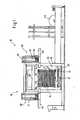
- Fig. 1 a strapping machine according to the invention in a view in the transport direction of the packages
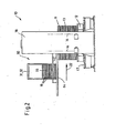
- Fig. 2 the object of Fig. 1 in a side view
- Fig. 3 the strapping machine according to the invention in a plan view in a simplified, not to scale representation
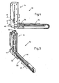
- Fig. 4 the applicator used in the strapping machine according to the invention with completely slaughtervoner transfer device in a side view;
- Fig. 5 the object of Fig. 4 in a perspective view
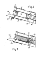
- Fig. 6 the object of Fig. 4 in section along the line BB;
- Fig. 7 the object of Fig. 4 in section along the line AA;
- Fig. 8 the applicator for the strapping machine according to the invention with partially extended transfer device in one Fig. 4 otherwise appropriate representation;
- Fig. 9 the object of Fig. 8 in perspective view.
- Fig. 10 the object of Fig. 8 in a section along the line CC.
- packages 11 which are, for example, on a pallet 12 stacked cardboard boxes 13 or the like.
- strapping 14 which consist of a plastic band, which is looped around the package, tensioned and then welded.
- edge wrapping elements 16 are laid out of thick cardboard when wrapping the package with the strapping between this and the package in the region of the longitudinal edges 15, which prevent the strained strapping 14 in the stacked on the pallet goods can impress.
- the strapping machine 10 has a transport device in the form of a roller conveyor 17, a conveyor frame 17 portal-like machine frame 18 with two upstanding side panels 19 and an upper, vertically mounted on the side panels mounted pressure bar 20 (not shown) with guide channels are part of a strapping, with the strap is wrapped around the package, as is known in the art.
- To the strapping further includes a lower guide lance 21, which moves after correct positioning of the package in the strapping machine transversely to the transport direction 22 in a space in the pallet 12 and thereby, together with the trained on the side panels and the pressure bar strip guide channels surrounding the package Band guide channel forms.
- the strapping machine also includes two applicators 30, by means of which the edge protection elements 16 are applied to the upper longitudinal edges 15 of the package 11 before the strapping 14 wraps around the package, thereby clamping the edge protection elements between itself and the package.
- the Applizier wornen 30 essentially consist of a memory device 31 with an upstanding stacking shaft 32, in which the edge protection elements 15 are received as storage stack 33, and from a transfer device 34, with the aid of the stockpiled in the stack shaft edge protection elements can be removed individually and transferred to the package.
- the arrangement according to the invention is such that the transfer device 34 at an angle ⁇ obliquely to the transport direction 22, that is aligned obliquely to the package edge 15 to which the edge protection element 16 is to be applied.
- the application devices can the machine frame laterally adjustable and be laterally displaced, for example by means of adjusting spindles 36 so that the edge protection elements, which have been advanced by the transfer devices of the Applizier Surpriseen invest in the area of the strapping to the protected edges of the package, as in Fig. 3 is indicated.
- edge protection elements which have been advanced by the transfer devices of the Applizier Surpriseen invest in the area of the strapping to the protected edges of the package, as in Fig. 3 is indicated.
- FIG. 4 to 10 is the structural design of one of the two in the machine after the Fig. 1 to 3 used Applizier Roaden and their mode of action shown in more detail.
- the Fig. 4 to 10 show the in the Fig. 1 and 3 Applicator arranged on the left side of the machine; the right-hand application device is correspondingly designed mirror-inverted.
- the applicator 30 has a holding plate 37, on which the stacking shaft 32 is mounted towering.
- the holding plate 37 also carries the transfer device 34, which consists essentially of a rodless pneumatic cylinder 38, which is provided at its front end with a driver 39 for a single edge protection element 16.
- the pneumatic cylinder 38 forms a holding and advancing element for the driver, which is in the fully retracted state of the pneumatic cylinder in a position below the memory device 31, in which he can take a single edge protection element on a bottom side of the stacking shaft 32 arranged single trigger 40 and hold ,
- the holding device used for this purpose is not shown in detail in the figures; it may be a mechanical device or also a suction device formed on the carrier, which holds the edge protection element by means of negative pressure. Other holding means can be used here.
- the driver 39 is pivotally connected to the holding and advancing element or slide, which is formed by the pneumatic cylinder 38 and about an axis 41 perpendicular to the feed direction 42 of the transfer device 34 is a piece pivot.
- the arrangement is such that the pivoting movement is automatically effected by a drive, which is formed essentially by a lateral guide element 43 for the transfer device 34, in particular for the driver 39, and a tensioned between the driver and the pneumatic cylinder arranged tension spring 44th , which pivots the driver by a limited by an oblique stop 45 angular amount ⁇ , as soon as the driver during advancement of the pneumatic cylinder in the direction of the Umreifungsstation from the sphere of action of the guide element 43rd comes ( Fig.
- the pivot angle by which the driver is swung back and forth again when the pneumatic cylinder is being retracted or retracted, corresponds to the angle ⁇ around which the transfer device 34 is arranged obliquely with respect to the transport direction 22.
- the driver is aligned parallel to the feed direction 42 in the area of the storage device and thus can take the lowest edge protection element from the stacking shaft in position and has pivoted in the region of the transfer point on the strapping in a position parallel to the transport direction, so that a positionally accurate transfer of the edge protection element can be made to the edge to be protected.
- the guide element 43 is designed curved at its outlet region 46, so that the pivotal movement of the driver when extending and retracting the transfer device is not abrupt, but a relatively gentle operation is guaranteed with little wear.
- the invention is not limited to the illustrated and described embodiment, but various changes and additions are conceivable without departing from the scope of the invention.
- the storage device would be arranged from the outset so that the position of the edge protection elements received therein is already adapted to the situation that should have the edge protection elements in their transfer to the package edge to be protected.
- edge protection elements must not be applied directly to the package edges by the transfer device, but it is also conceivable to advance the edge protection elements of the transfer device initially to a transfer point, where they are detected by additional grippers and then applied to the transport direction of the packages to this before the strapping device winds the strapping band around the package while clamping the applied edge protection element between itself and the package.
Landscapes
- Engineering & Computer Science (AREA)
- Mechanical Engineering (AREA)
- Basic Packing Technique (AREA)
Abstract
Claims (8)
- Cercleuse pour paquets d'emballage, comprenant un dispositif de transport pour les paquets d'emballage à cercler, avec un dispositif de cerclage enserrant les paquets d'emballage avec au moins une bande de cerclage transversalement à la direction de transport du dispositif de transport et avec aumoins un dispositif d'application pour des éléments de protection d'arêtes, qui peuvent être placés pour protéger les arêtes des paquets d'emballage dans la zone de la bande de cerclage enserrant le paquet d'emballage entre celle-ci et le paquet d'emballage, dans laquelle le dispositif d'application présente un dispositif de stockage pour les éléments de protection d'arêtes, ainsi qu'un dispositif de transmission prélevant individuellement les éléments de protection d'arêtes du dispositif de stockage et les transférant au paquet d'emballage et/ou au dispositif de cerclage, qui est orienté sous un certain angle en oblique par rapport à la direction de transport et qui présente un entraîneur pour un élément de protection d'arêtes individuel pouvant être déplacé en oblique par rapport à la direction de transport entre le dispositif de stockage et un point de transmission sur le dispositif de cerclage, caractérisée en ce que l'entraîneur (39) peut pivoter entre le dispositif de stockage et le point de transmission d'une valeur angulaire (β), qui correspond à l'angle (α) entre la direction de transport (22) ou l'arête du paquet d'emballage et le dispositif de transmission (34) orienté en oblique par rapport à celle-ci.
- Cercleuse selon la revendication 1, caractérisée en ce que le dispositif de stockage (31) présente un puits d'empilement (32) pour les éléments de protection d'arêtes (16) avec une évacuation individuelle (40) par le bas.
- Cercleuse selon la revendication 1 ou 2, caractérisée en ce que l'entraîneur (39) peut être déplacé au moyen d'un poussoir (38) agencé sur le dispositif de stockage (31) et/ou sur le côté inférieur du puits d'empilement, de préférence actionné par un cylindre.
- Cercleuse selon l'une quelconque des revendications 1 à 3, caractérisée en ce que l'entraîneur (39) est orienté dans la zone du dispositif de stockage (31) dans la direction d'avancement (42) du dispositif de transmission (34) et est orienté dans la zone du point de transmission dans la direction de transport (22) du paquet d'emballage (11) ou de son arête (15).
- Cercleuse selon l'une quelconque des revendications 1 à 4, caractérisée en ce que l'entraîneur (39) est monté à pivotement sur un élément de retenue et d'avancement (38) autour d'un axe (41) perpendiculairement à la direction d'avancement (42) et/ou à la direction de transport (22).
- Cercleuse selon la revendication 5, caractérisée par un entraînement (43, 44, 45) pour faire pivoter l'entraîneur (39) par rapport à l'élément de retenue et d'avancement (38) pendant l'opération de déplacement du dispositif de transmission.
- Cercleuse selon la revendication 6, caractérisée en ce que l'entraînement est formé sensiblement par un élément de guidage (43) agencé latéralement sur le trajet de déplacement du dispositif de transmission (34), se terminant entre le dispositif de stockage (31) et le point de transmission et orientant l'entraîneur (39) dans la zone du dispositif de stockage (31) en position parallèle à la direction d'avancement (42) et par un ressort de réglage (44) opérant entre l'entraîneur (39) et l'élément de retenue et d'avancement (38) et faisant pivoter l'entraîneur en dehors de la zone d'action de l'élément de guidage (43) dans une position parallèle à la direction de transport (22) ou à l'arête de paquet d'emballage (15).
- Cercleuse selon la revendication 7, caractérisée en ce que l'élément de guidage (43) est incurvé sur sa zone de sortie (46).
Priority Applications (1)
| Application Number | Priority Date | Filing Date | Title |
|---|---|---|---|
| PL09786901T PL2328811T3 (pl) | 2008-09-11 | 2009-08-11 | Opasowywarka do przedmiotów pakowanych |
Applications Claiming Priority (2)
| Application Number | Priority Date | Filing Date | Title |
|---|---|---|---|
| DE102008046888A DE102008046888B4 (de) | 2008-09-11 | 2008-09-11 | Umreifungsmaschine für Packstücke |
| PCT/IB2009/053537 WO2010029451A1 (fr) | 2008-09-11 | 2009-08-11 | Enrubaneuse pour paquets |
Publications (2)
| Publication Number | Publication Date |
|---|---|
| EP2328811A1 EP2328811A1 (fr) | 2011-06-08 |
| EP2328811B1 true EP2328811B1 (fr) | 2012-07-11 |
Family
ID=41396201
Family Applications (1)
| Application Number | Title | Priority Date | Filing Date |
|---|---|---|---|
| EP09786901A Not-in-force EP2328811B1 (fr) | 2008-09-11 | 2009-08-11 | Enrubaneuse pour paquets |
Country Status (5)
| Country | Link |
|---|---|
| EP (1) | EP2328811B1 (fr) |
| DE (1) | DE102008046888B4 (fr) |
| DK (1) | DK2328811T3 (fr) |
| PL (1) | PL2328811T3 (fr) |
| WO (1) | WO2010029451A1 (fr) |
Families Citing this family (6)
| Publication number | Priority date | Publication date | Assignee | Title |
|---|---|---|---|---|
| CN103723299A (zh) * | 2012-10-10 | 2014-04-16 | 鸿富锦精密工业(深圳)有限公司 | 包边装置 |
| DE102015113350A1 (de) * | 2015-08-13 | 2017-02-16 | Signode Industrial Group Llc | Umreifungsvorrichtung für Packstücke und Verfahren zum Umreifen |
| DE202016102880U1 (de) | 2016-05-31 | 2017-09-03 | Cyklop Gmbh | Umreifungsmaschine für Packstücke |
| US11174051B2 (en) | 2019-02-15 | 2021-11-16 | Samuel, Son & Co. (Usa) Inc. | Hand held strapping tool |
| DE102019107702B3 (de) | 2019-03-26 | 2020-05-28 | Signode Industrial Group Llc | Verfahren zur Anordnung eines Kantenschutzmittels an einem Packstück in einer Vorrichtung zum Umreifen von Packstücken sowie Vorrichtung zum Umreifen von Packstücken |
| US12397943B2 (en) | 2022-11-29 | 2025-08-26 | Samuel, Son & Co. (Usa) Inc. | Handheld strapping device |
Family Cites Families (6)
| Publication number | Priority date | Publication date | Assignee | Title |
|---|---|---|---|---|
| DE8018309U1 (de) * | 1980-12-18 | Lux Systemtechnik Gmbh, 1000 Berlin | Leistenzuführvorrichtung | |
| DE3110061A1 (de) * | 1981-03-16 | 1982-09-30 | Hellmann GmbH, 3160 Lehrte | Geraet zum auflegen von kantenschutzwinkeln auf stueckgueter |
| US4587791A (en) * | 1984-12-24 | 1986-05-13 | United States Steel Corporation | Edge protector positioning apparatus |
| DE9311406U1 (de) * | 1993-07-30 | 1993-11-11 | Cyklop GmbH, 50996 Köln | Packpresse |
| DE10012484A1 (de) * | 2000-03-15 | 2001-09-20 | Sander Gmbh | Vorrichtung zum Umreifen von Packstücken |
| DE202007018468U1 (de) * | 2007-11-13 | 2008-08-28 | Cyklop Gmbh | Umreifungsmaschine für Packstücke |
-
2008
- 2008-09-11 DE DE102008046888A patent/DE102008046888B4/de not_active Expired - Fee Related
-
2009
- 2009-08-11 WO PCT/IB2009/053537 patent/WO2010029451A1/fr not_active Ceased
- 2009-08-11 PL PL09786901T patent/PL2328811T3/pl unknown
- 2009-08-11 EP EP09786901A patent/EP2328811B1/fr not_active Not-in-force
- 2009-08-11 DK DK09786901.0T patent/DK2328811T3/da active
Also Published As
| Publication number | Publication date |
|---|---|
| PL2328811T3 (pl) | 2012-10-31 |
| DE102008046888A1 (de) | 2010-04-08 |
| DK2328811T3 (da) | 2012-08-20 |
| WO2010029451A1 (fr) | 2010-03-18 |
| DE102008046888B4 (de) | 2011-04-21 |
| EP2328811A1 (fr) | 2011-06-08 |
Similar Documents
| Publication | Publication Date | Title |
|---|---|---|
| EP2328811B1 (fr) | Enrubaneuse pour paquets | |
| DE69122080T2 (de) | Verfahren, maschine und einrichtung zum verpacken einer mit einem kantenschutzstreifen versehenen ladung, vorrichtung zum ergreifen, fördern, ablegen und halten eines dergleichen streifens | |
| DE2324293C3 (de) | Vorrichtung zum Umschnüren eines Ballens o.dgl | |
| DE29907459U1 (de) | Verpackungsmaschine | |
| DE102017116458B3 (de) | Vorrichtung und Verfahren zum Verpacken gestapelter länglicher Gegenstände sowie Verwendung einer derartigen Vorrichtung | |
| DE2431153A1 (de) | Maschine zum umreifen von packstuecken | |
| DE202007018468U1 (de) | Umreifungsmaschine für Packstücke | |
| DE2334565C3 (de) | Vorrichtung zum Transport quaderförmiger Behälter aus biegsamen Material | |
| DE2403261C3 (de) | Vorrichtung zum automatischen Umreifen | |
| DE9311406U1 (de) | Packpresse | |
| DE1461760A1 (de) | Verpackungsmaschine | |
| DE3032642A1 (de) | Umschnuermaschine | |
| DE202016102880U1 (de) | Umreifungsmaschine für Packstücke | |
| EP3169591B1 (fr) | Procédé et dispositif de fabrication des gerbes de cerclage | |
| DE2421539B2 (de) | Vorrichtung zum Einwickeln quaderförmiger Gegenstande | |
| DE7728960U1 (de) | Vorrichtung zum aufstossen von blattmaterial-bogen zu einem stapel | |
| DE6809225U (de) | Maschine zum verpacken von struempfen | |
| DE2904554A1 (de) | Verfahren zum einlegen von flossenpackungen in einen behaelter und einrichtung zur durchfuehrung des verfahrens | |
| DD224556A5 (de) | Vorrichtung zum kontinuierlichen einspeisen (eintakten) von im wesentlichen flachen warenstuecken der genuss- oder lebensmittelbranche, insbesondere schokoladentafeln oder -riegel, in eine packmaschine | |
| DE19503472A1 (de) | Vorrichtung zum Vereinzeln von Werkstücken | |
| CH644504A5 (de) | Vorrichtung zur anbringung von schiebern an reissverschlussstreifen. | |
| DE102010012308A1 (de) | Buchtransportklammer für Klebebinder | |
| DE2503029C2 (de) | Vorrichtung zum Einwickeln rechteckiger Gegenstände | |
| CH647993A5 (de) | Vorrichtung und verfahren zum umschnueren eines gegenstandes. | |
| DE3030333C2 (fr) |
Legal Events
| Date | Code | Title | Description |
|---|---|---|---|
| PUAI | Public reference made under article 153(3) epc to a published international application that has entered the european phase |
Free format text: ORIGINAL CODE: 0009012 |
|
| 17P | Request for examination filed |
Effective date: 20110411 |
|
| AK | Designated contracting states |
Kind code of ref document: A1 Designated state(s): AT BE BG CH CY CZ DE DK EE ES FI FR GB GR HR HU IE IS IT LI LT LU LV MC MK MT NL NO PL PT RO SE SI SK SM TR |
|
| AX | Request for extension of the european patent |
Extension state: AL BA RS |
|
| DAX | Request for extension of the european patent (deleted) | ||
| GRAP | Despatch of communication of intention to grant a patent |
Free format text: ORIGINAL CODE: EPIDOSNIGR1 |
|
| GRAS | Grant fee paid |
Free format text: ORIGINAL CODE: EPIDOSNIGR3 |
|
| GRAA | (expected) grant |
Free format text: ORIGINAL CODE: 0009210 |
|
| AK | Designated contracting states |
Kind code of ref document: B1 Designated state(s): AT BE BG CH CY CZ DE DK EE ES FI FR GB GR HR HU IE IS IT LI LT LU LV MC MK MT NL NO PL PT RO SE SI SK SM TR |
|
| REG | Reference to a national code |
Ref country code: GB Ref legal event code: FG4D Free format text: NOT ENGLISH |
|
| REG | Reference to a national code |
Ref country code: CH Ref legal event code: EP |
|
| REG | Reference to a national code |
Ref country code: AT Ref legal event code: REF Ref document number: 565974 Country of ref document: AT Kind code of ref document: T Effective date: 20120715 |
|
| REG | Reference to a national code |
Ref country code: IE Ref legal event code: FG4D Free format text: LANGUAGE OF EP DOCUMENT: GERMAN |
|
| REG | Reference to a national code |
Ref country code: DK Ref legal event code: T3 |
|
| REG | Reference to a national code |
Ref country code: NL Ref legal event code: T3 |
|
| REG | Reference to a national code |
Ref country code: DE Ref legal event code: R096 Ref document number: 502009004101 Country of ref document: DE Effective date: 20120906 |
|
| REG | Reference to a national code |
Ref country code: SE Ref legal event code: TRGR |
|
| REG | Reference to a national code |
Ref country code: PL Ref legal event code: T3 |
|
| REG | Reference to a national code |
Ref country code: LT Ref legal event code: MG4D Effective date: 20120711 |
|
| PG25 | Lapsed in a contracting state [announced via postgrant information from national office to epo] |
Ref country code: IS Free format text: LAPSE BECAUSE OF FAILURE TO SUBMIT A TRANSLATION OF THE DESCRIPTION OR TO PAY THE FEE WITHIN THE PRESCRIBED TIME-LIMIT Effective date: 20121111 Ref country code: HR Free format text: LAPSE BECAUSE OF FAILURE TO SUBMIT A TRANSLATION OF THE DESCRIPTION OR TO PAY THE FEE WITHIN THE PRESCRIBED TIME-LIMIT Effective date: 20120711 Ref country code: NO Free format text: LAPSE BECAUSE OF FAILURE TO SUBMIT A TRANSLATION OF THE DESCRIPTION OR TO PAY THE FEE WITHIN THE PRESCRIBED TIME-LIMIT Effective date: 20121011 Ref country code: LT Free format text: LAPSE BECAUSE OF FAILURE TO SUBMIT A TRANSLATION OF THE DESCRIPTION OR TO PAY THE FEE WITHIN THE PRESCRIBED TIME-LIMIT Effective date: 20120711 Ref country code: CY Free format text: LAPSE BECAUSE OF FAILURE TO SUBMIT A TRANSLATION OF THE DESCRIPTION OR TO PAY THE FEE WITHIN THE PRESCRIBED TIME-LIMIT Effective date: 20120711 |
|
| PG25 | Lapsed in a contracting state [announced via postgrant information from national office to epo] |
Ref country code: GR Free format text: LAPSE BECAUSE OF FAILURE TO SUBMIT A TRANSLATION OF THE DESCRIPTION OR TO PAY THE FEE WITHIN THE PRESCRIBED TIME-LIMIT Effective date: 20121012 Ref country code: LV Free format text: LAPSE BECAUSE OF FAILURE TO SUBMIT A TRANSLATION OF THE DESCRIPTION OR TO PAY THE FEE WITHIN THE PRESCRIBED TIME-LIMIT Effective date: 20120711 Ref country code: PT Free format text: LAPSE BECAUSE OF FAILURE TO SUBMIT A TRANSLATION OF THE DESCRIPTION OR TO PAY THE FEE WITHIN THE PRESCRIBED TIME-LIMIT Effective date: 20121112 Ref country code: SI Free format text: LAPSE BECAUSE OF FAILURE TO SUBMIT A TRANSLATION OF THE DESCRIPTION OR TO PAY THE FEE WITHIN THE PRESCRIBED TIME-LIMIT Effective date: 20120711 |
|
| PG25 | Lapsed in a contracting state [announced via postgrant information from national office to epo] |
Ref country code: MC Free format text: LAPSE BECAUSE OF NON-PAYMENT OF DUE FEES Effective date: 20120831 |
|
| PG25 | Lapsed in a contracting state [announced via postgrant information from national office to epo] |
Ref country code: CZ Free format text: LAPSE BECAUSE OF FAILURE TO SUBMIT A TRANSLATION OF THE DESCRIPTION OR TO PAY THE FEE WITHIN THE PRESCRIBED TIME-LIMIT Effective date: 20120711 Ref country code: ES Free format text: LAPSE BECAUSE OF FAILURE TO SUBMIT A TRANSLATION OF THE DESCRIPTION OR TO PAY THE FEE WITHIN THE PRESCRIBED TIME-LIMIT Effective date: 20121022 Ref country code: EE Free format text: LAPSE BECAUSE OF FAILURE TO SUBMIT A TRANSLATION OF THE DESCRIPTION OR TO PAY THE FEE WITHIN THE PRESCRIBED TIME-LIMIT Effective date: 20120711 Ref country code: RO Free format text: LAPSE BECAUSE OF FAILURE TO SUBMIT A TRANSLATION OF THE DESCRIPTION OR TO PAY THE FEE WITHIN THE PRESCRIBED TIME-LIMIT Effective date: 20120711 |
|
| PLBE | No opposition filed within time limit |
Free format text: ORIGINAL CODE: 0009261 |
|
| REG | Reference to a national code |
Ref country code: FR Ref legal event code: ST Effective date: 20130430 |
|
| STAA | Information on the status of an ep patent application or granted ep patent |
Free format text: STATUS: NO OPPOSITION FILED WITHIN TIME LIMIT |
|
| REG | Reference to a national code |
Ref country code: IE Ref legal event code: MM4A |
|
| PG25 | Lapsed in a contracting state [announced via postgrant information from national office to epo] |
Ref country code: SK Free format text: LAPSE BECAUSE OF FAILURE TO SUBMIT A TRANSLATION OF THE DESCRIPTION OR TO PAY THE FEE WITHIN THE PRESCRIBED TIME-LIMIT Effective date: 20120711 Ref country code: IT Free format text: LAPSE BECAUSE OF FAILURE TO SUBMIT A TRANSLATION OF THE DESCRIPTION OR TO PAY THE FEE WITHIN THE PRESCRIBED TIME-LIMIT Effective date: 20120711 |
|
| 26N | No opposition filed |
Effective date: 20130412 |
|
| PG25 | Lapsed in a contracting state [announced via postgrant information from national office to epo] |
Ref country code: IE Free format text: LAPSE BECAUSE OF NON-PAYMENT OF DUE FEES Effective date: 20120811 Ref country code: BG Free format text: LAPSE BECAUSE OF FAILURE TO SUBMIT A TRANSLATION OF THE DESCRIPTION OR TO PAY THE FEE WITHIN THE PRESCRIBED TIME-LIMIT Effective date: 20121011 |
|
| REG | Reference to a national code |
Ref country code: DE Ref legal event code: R097 Ref document number: 502009004101 Country of ref document: DE Effective date: 20130412 |
|
| PG25 | Lapsed in a contracting state [announced via postgrant information from national office to epo] |
Ref country code: FR Free format text: LAPSE BECAUSE OF NON-PAYMENT OF DUE FEES Effective date: 20120911 |
|
| PG25 | Lapsed in a contracting state [announced via postgrant information from national office to epo] |
Ref country code: MT Free format text: LAPSE BECAUSE OF FAILURE TO SUBMIT A TRANSLATION OF THE DESCRIPTION OR TO PAY THE FEE WITHIN THE PRESCRIBED TIME-LIMIT Effective date: 20120711 |
|
| REG | Reference to a national code |
Ref country code: CH Ref legal event code: PL |
|
| PG25 | Lapsed in a contracting state [announced via postgrant information from national office to epo] |
Ref country code: TR Free format text: LAPSE BECAUSE OF FAILURE TO SUBMIT A TRANSLATION OF THE DESCRIPTION OR TO PAY THE FEE WITHIN THE PRESCRIBED TIME-LIMIT Effective date: 20120711 Ref country code: LI Free format text: LAPSE BECAUSE OF NON-PAYMENT OF DUE FEES Effective date: 20130831 Ref country code: CH Free format text: LAPSE BECAUSE OF NON-PAYMENT OF DUE FEES Effective date: 20130831 |
|
| PG25 | Lapsed in a contracting state [announced via postgrant information from national office to epo] |
Ref country code: SM Free format text: LAPSE BECAUSE OF FAILURE TO SUBMIT A TRANSLATION OF THE DESCRIPTION OR TO PAY THE FEE WITHIN THE PRESCRIBED TIME-LIMIT Effective date: 20120711 Ref country code: LU Free format text: LAPSE BECAUSE OF NON-PAYMENT OF DUE FEES Effective date: 20120811 |
|
| PG25 | Lapsed in a contracting state [announced via postgrant information from national office to epo] |
Ref country code: HU Free format text: LAPSE BECAUSE OF FAILURE TO SUBMIT A TRANSLATION OF THE DESCRIPTION OR TO PAY THE FEE WITHIN THE PRESCRIBED TIME-LIMIT Effective date: 20090811 |
|
| PG25 | Lapsed in a contracting state [announced via postgrant information from national office to epo] |
Ref country code: MK Free format text: LAPSE BECAUSE OF FAILURE TO SUBMIT A TRANSLATION OF THE DESCRIPTION OR TO PAY THE FEE WITHIN THE PRESCRIBED TIME-LIMIT Effective date: 20120711 |
|
| REG | Reference to a national code |
Ref country code: AT Ref legal event code: MM01 Ref document number: 565974 Country of ref document: AT Kind code of ref document: T Effective date: 20140811 |
|
| PG25 | Lapsed in a contracting state [announced via postgrant information from national office to epo] |
Ref country code: AT Free format text: LAPSE BECAUSE OF NON-PAYMENT OF DUE FEES Effective date: 20140811 |
|
| PGFP | Annual fee paid to national office [announced via postgrant information from national office to epo] |
Ref country code: PL Payment date: 20160810 Year of fee payment: 8 |
|
| PG25 | Lapsed in a contracting state [announced via postgrant information from national office to epo] |
Ref country code: BE Free format text: LAPSE BECAUSE OF NON-PAYMENT OF DUE FEES Effective date: 20160831 |
|
| PGFP | Annual fee paid to national office [announced via postgrant information from national office to epo] |
Ref country code: FI Payment date: 20161219 Year of fee payment: 8 Ref country code: GB Payment date: 20161222 Year of fee payment: 8 Ref country code: DK Payment date: 20161222 Year of fee payment: 8 Ref country code: NL Payment date: 20161221 Year of fee payment: 8 Ref country code: DE Payment date: 20161216 Year of fee payment: 8 |
|
| PGFP | Annual fee paid to national office [announced via postgrant information from national office to epo] |
Ref country code: SE Payment date: 20161222 Year of fee payment: 8 Ref country code: BE Payment date: 20161221 Year of fee payment: 8 |
|
| PGRI | Patent reinstated in contracting state [announced from national office to epo] |
Ref country code: BE Effective date: 20161222 |
|
| REG | Reference to a national code |
Ref country code: DE Ref legal event code: R119 Ref document number: 502009004101 Country of ref document: DE |
|
| REG | Reference to a national code |
Ref country code: DK Ref legal event code: EBP Effective date: 20170831 |
|
| REG | Reference to a national code |
Ref country code: NL Ref legal event code: MM Effective date: 20170901 |
|
| GBPC | Gb: european patent ceased through non-payment of renewal fee |
Effective date: 20170811 |
|
| PG25 | Lapsed in a contracting state [announced via postgrant information from national office to epo] |
Ref country code: SE Free format text: LAPSE BECAUSE OF NON-PAYMENT OF DUE FEES Effective date: 20170812 Ref country code: FI Free format text: LAPSE BECAUSE OF NON-PAYMENT OF DUE FEES Effective date: 20170811 |
|
| REG | Reference to a national code |
Ref country code: BE Ref legal event code: MM Effective date: 20170831 |
|
| PG25 | Lapsed in a contracting state [announced via postgrant information from national office to epo] |
Ref country code: NL Free format text: LAPSE BECAUSE OF NON-PAYMENT OF DUE FEES Effective date: 20170901 |
|
| PG25 | Lapsed in a contracting state [announced via postgrant information from national office to epo] |
Ref country code: DE Free format text: LAPSE BECAUSE OF NON-PAYMENT OF DUE FEES Effective date: 20180301 Ref country code: GB Free format text: LAPSE BECAUSE OF NON-PAYMENT OF DUE FEES Effective date: 20170811 Ref country code: DK Free format text: LAPSE BECAUSE OF NON-PAYMENT OF DUE FEES Effective date: 20170831 |
|
| PG25 | Lapsed in a contracting state [announced via postgrant information from national office to epo] |
Ref country code: BE Free format text: LAPSE BECAUSE OF NON-PAYMENT OF DUE FEES Effective date: 20170831 |
|
| PG25 | Lapsed in a contracting state [announced via postgrant information from national office to epo] |
Ref country code: PL Free format text: LAPSE BECAUSE OF NON-PAYMENT OF DUE FEES Effective date: 20170811 |