EP2328811B1 - Strapping machine for packages - Google Patents
Strapping machine for packages Download PDFInfo
- Publication number
- EP2328811B1 EP2328811B1 EP09786901A EP09786901A EP2328811B1 EP 2328811 B1 EP2328811 B1 EP 2328811B1 EP 09786901 A EP09786901 A EP 09786901A EP 09786901 A EP09786901 A EP 09786901A EP 2328811 B1 EP2328811 B1 EP 2328811B1
- Authority
- EP
- European Patent Office
- Prior art keywords
- package
- strapping
- storage device
- edge protection
- carrier
- Prior art date
- Legal status (The legal status is an assumption and is not a legal conclusion. Google has not performed a legal analysis and makes no representation as to the accuracy of the status listed.)
- Not-in-force
Links
Images


Classifications
-
- B—PERFORMING OPERATIONS; TRANSPORTING
- B65—CONVEYING; PACKING; STORING; HANDLING THIN OR FILAMENTARY MATERIAL
- B65B—MACHINES, APPARATUS OR DEVICES FOR, OR METHODS OF, PACKAGING ARTICLES OR MATERIALS; UNPACKING
- B65B13/00—Bundling articles
- B65B13/18—Details of, or auxiliary devices used in, bundling machines or bundling tools
- B65B13/181—Details of, or auxiliary devices used in, bundling machines or bundling tools applying edge protecting members during bundling
-
- B—PERFORMING OPERATIONS; TRANSPORTING
- B65—CONVEYING; PACKING; STORING; HANDLING THIN OR FILAMENTARY MATERIAL
- B65B—MACHINES, APPARATUS OR DEVICES FOR, OR METHODS OF, PACKAGING ARTICLES OR MATERIALS; UNPACKING
- B65B27/00—Bundling particular articles presenting special problems using string, wire, or narrow tape or band; Baling fibrous material, e.g. peat, not otherwise provided for
- B65B27/08—Bundling paper sheets, envelopes, bags, newspapers, or other thin flat articles
Definitions
- the invention relates to a strapping machine for packages, comprising a transport device for the packages to be strapped, with a strapping device wrapping the packages with at least one strapping transversely to the transport direction of the transport device and with at least one application for edge protection elements, which protect the edges of the packages in the the package wrap around strapping between this and the package are attached, the applicator having a memory device for the edge protection elements and the edge protection elements from the storage device individually removing and transferring to the package and / or Umreifungs coupled transfer device, which is aligned at an angle obliquely to the transport direction is and an obliquely to the transport direction between the storage device and a transfer point on the strapping M displaceable having takers for a single edge protection element.
- Packages such as on a pallet stacked cardboard or squared timbers are often provided for their transport straps with plastic straps, which are placed around the package by means of a strapping machine and securely hold together during subsequent transport.
- Especially packs of pressure-sensitive materials are provided at their edges before strapping and closing the strapping with edge protection elements, which usually consist of a kinked, thick cardboard and prevent the strapping in the edge region, the packages in harmful and undue pressure and thereby damage.
- the edge protection elements are using an applicator applied to the edges of the packages before the strap is wrapped around the package and firmly clamped before welding.
- Such a strapping machine is for example in the DE 20 2007 018 468-U the applicant described.
- the Applizier worn in this strapping machine consists essentially of a storage device with a magazine for the stacked edge protection elements, which are individually removed from a arranged below the memory slide and advanced parallel to the transport direction of the packages up to the level of strapping, where they are taken from suckers and be placed transversely to the transport direction against the edges of the package.
- the known machine has proven itself in practice, it has the disadvantage that it must have a comparatively large overall width which is at least as great as the width of the package plus the space which the applicator requires laterally next to the supplied package.
- the transfer of the edge protection elements from the feed slide to the suction pads, which then create the edge protection elements transversely against the edges of the package relatively expensive and the mechanical and control effort required for this large.
- the magazines for the edge protection angle laterally next to the package to be strapped in the working area of the strapping device with the above-mentioned disadvantage that the machine must have a relatively large width, which is at least as large as the width of the package plus the square, the the applicator for the edge protection elements including the magazine provided for receiving them is needed laterally next to the package to be strapped.
- the DE-U 80 18 309 discloses a device for supplying strips for protecting a transported goods to be strapped with two feeders arranged on slide rails, which are designed in the form of a double slide and are each provided with a magazine for holding protective strips and a supply unit, which is designed in the form of a movable table.
- the arrangement is such that the feed devices are arranged by means of a linkage horizontally movable horizontally on the slide rails and the supply unit is equipped with a pneumatic cylinder for the strip delivery.
- the from the DE 100 12 484 A1 or the corresponding one EP 1 136 360 A Known device uses grippers to remove edge protection angle from a magazine and apply it to the edges of a package to be strapped.
- the edge protection angle in the transfer process from the gripper does not fall, it is proposed in this document to design the gripper as a needle gripper.
- the grippers are in a plane parallel to the strapping plane and work, being worn on portal inwardly facing arms of the vertical columns of the strapping and a telescopic arm seats, which in turn is rotatably guided horizontally.
- the relatively heavy gripper must be moved on its way from the acquisition of the edge protection angle from the magazine for transfer to the package about several axes translational and rotational.
- the actual driver for the edge protection angle which is formed by a claw jaw forming cutout, is rigidly mounted on the transfer device.
- a device is known from DE-93 11 406-U known.
- the driver for the edge protection elements is part of a slider, having a stepped support surface with an angular stop surface on which the respective lowest edge protection element, which is removed from a magazine, abuts with a corner.
- This embodiment makes it necessary that the edge protection elements received in the storage device must already be correctly aligned with the package in the storage device.
- the object of the invention is to design a strapping machine of the generic type such that the collated edge protection elements need not already be accommodated in the storage device for the package.
- driver between the storage device and the transfer point is pivotable by an angular amount corresponding to the angle between the transport direction or the package edge and the obliquely aligned transfer device.
- the storage device can be arranged laterally offset from the transport path of the packages and thus in a region in which collisions between the package and the applicator can not occur if the package along the transport direction with the Transport device is conveyed to Umreifungsstation.
- the obliquely oriented to the transport direction transfer device takes from the storage device an edge protection element and transports this at an angle obliquely to the transport direction to Umreifungs driven where the edge protection element then comes into contact with the protected edge of the package and upon actuation of the strapping between the strapping and the package is trapped.
- the transfer device Due to the oblique transport of the edge protection elements, which takes place in the described, preferred manner up to the edges of the package, an additional takeover of the edge protection elements by means of a suction pad or the like. Is unnecessary to make the edge protection elements transversely to the transport direction against the package ,
- the transfer device according to the invention has an obliquely to the transport direction between the storage device and a transfer point on the strapping device slidable driver for a single edge protection element. The driver drives under the storage device and pushes out the bottom of the stacked in a shaft edge protection element and takes this on his way with, until it can be handed over at the transfer point on the strapping and applied to the edge of the package to be protected.
- the driver according to the invention between the storage device and the transfer point is pivotable by an angular amount corresponding to the angle between the transport direction or the package edge and the obliquely aligned transfer device, recorded in the memory device edge protection elements are not already taken aligned in the storage device to the package be, but causes the pivotable carrier that the removed from him edge protection element, which was received obliquely aligned in the storage device to the package, pivots after its removal from the memory of the driver and thereby aligned in its correct position.
- the storage device can have a stacking shaft for the edge protection elements with individual discharge on the underside.
- the driver is preferably displaceable by means of a arranged on the storage device and / or on the underside of the stacking shaft, preferably a cylinder-operated slide.
- the driver is preferably aligned in the region of the storage device to the feed direction of the transfer device, while it is aligned in the region of the transfer point to the transport direction of the package or its package edge.
- the driver is pivotally mounted on a holding and advancing element about an axis perpendicular to the feed direction and / or to the transport direction of the packages.
- a drive which is advantageously formed essentially of a laterally arranged on the travel path of the transfer device, between the storage device and the transfer point and the driver in the storage device in a position parallel to the feed direction guiding and one between the driver and the holding and advancing element effective, the driver outside the range of action of the guide element in a position parallel to the transport direction or the package edge pivoting spring.
- This arrangement causes an automatic pivoting of the driver, as soon as it passes out of the effective range of the guide element during the movement process of the transfer device, in the position aligned parallel to the transport direction.
- the driver is then pivoted back into the position, which is aligned parallel to the feed direction of the transfer device, as soon as the driver comes back into the sphere of action of the guide element.
- the storage device can have a stacking shaft for the edge protection elements with individual discharge on the underside.
- the driver is preferably displaceable by means of a arranged on the storage device and / or on the underside of the stacking shaft, preferably a cylinder-operated slide.
- the driver is preferably aligned in the region of the storage device to the feed direction of the transfer device, while it is aligned in the region of the transfer point to the transport direction of the package or its package edge.
- the driver is pivotally mounted on a holding and advancing element about an axis perpendicular to the feed direction and / or to the transport direction of the packages.
- a drive may be provided which is expediently essentially formed by a laterally arranged on the travel path of the transfer device, ending between the storage device and the transfer point and the driver in the area the storage device in a position parallel to the feed direction aligning guide and an effective between the driver and the holding and advancing element, the driver outside the effective range of the guide into a position parallel to the transport direction or the package edge pivoting spring.
- This arrangement causes an automatic pivoting of the driver, as soon as it passes out of the effective range of the guide element during the movement process of the transfer device, in the position aligned parallel to the transport direction.
- the driver is then pivoted back into the position, which is aligned parallel to the feed direction of the transfer device, as soon as the driver comes back into the sphere of action of the guide element.
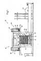
- Fig. 1 a strapping machine according to the invention in a view in the transport direction of the packages
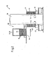
- Fig. 2 the object of Fig. 1 in a side view
- Fig. 3 the strapping machine according to the invention in a plan view in a simplified, not to scale representation
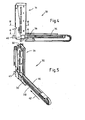
- Fig. 4 the applicator used in the strapping machine according to the invention with completely slaughtervoner transfer device in a side view;
- Fig. 5 the object of Fig. 4 in a perspective view
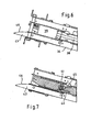
- Fig. 6 the object of Fig. 4 in section along the line BB;
- Fig. 7 the object of Fig. 4 in section along the line AA;
- Fig. 8 the applicator for the strapping machine according to the invention with partially extended transfer device in one Fig. 4 otherwise appropriate representation;
- Fig. 9 the object of Fig. 8 in perspective view.
- Fig. 10 the object of Fig. 8 in a section along the line CC.
- packages 11 which are, for example, on a pallet 12 stacked cardboard boxes 13 or the like.
- strapping 14 which consist of a plastic band, which is looped around the package, tensioned and then welded.
- edge wrapping elements 16 are laid out of thick cardboard when wrapping the package with the strapping between this and the package in the region of the longitudinal edges 15, which prevent the strained strapping 14 in the stacked on the pallet goods can impress.
- the strapping machine 10 has a transport device in the form of a roller conveyor 17, a conveyor frame 17 portal-like machine frame 18 with two upstanding side panels 19 and an upper, vertically mounted on the side panels mounted pressure bar 20 (not shown) with guide channels are part of a strapping, with the strap is wrapped around the package, as is known in the art.
- To the strapping further includes a lower guide lance 21, which moves after correct positioning of the package in the strapping machine transversely to the transport direction 22 in a space in the pallet 12 and thereby, together with the trained on the side panels and the pressure bar strip guide channels surrounding the package Band guide channel forms.
- the strapping machine also includes two applicators 30, by means of which the edge protection elements 16 are applied to the upper longitudinal edges 15 of the package 11 before the strapping 14 wraps around the package, thereby clamping the edge protection elements between itself and the package.
- the Applizier wornen 30 essentially consist of a memory device 31 with an upstanding stacking shaft 32, in which the edge protection elements 15 are received as storage stack 33, and from a transfer device 34, with the aid of the stockpiled in the stack shaft edge protection elements can be removed individually and transferred to the package.
- the arrangement according to the invention is such that the transfer device 34 at an angle ⁇ obliquely to the transport direction 22, that is aligned obliquely to the package edge 15 to which the edge protection element 16 is to be applied.
- the application devices can the machine frame laterally adjustable and be laterally displaced, for example by means of adjusting spindles 36 so that the edge protection elements, which have been advanced by the transfer devices of the Applizier Surpriseen invest in the area of the strapping to the protected edges of the package, as in Fig. 3 is indicated.
- edge protection elements which have been advanced by the transfer devices of the Applizier Surpriseen invest in the area of the strapping to the protected edges of the package, as in Fig. 3 is indicated.
- FIG. 4 to 10 is the structural design of one of the two in the machine after the Fig. 1 to 3 used Applizier Roaden and their mode of action shown in more detail.
- the Fig. 4 to 10 show the in the Fig. 1 and 3 Applicator arranged on the left side of the machine; the right-hand application device is correspondingly designed mirror-inverted.
- the applicator 30 has a holding plate 37, on which the stacking shaft 32 is mounted towering.
- the holding plate 37 also carries the transfer device 34, which consists essentially of a rodless pneumatic cylinder 38, which is provided at its front end with a driver 39 for a single edge protection element 16.
- the pneumatic cylinder 38 forms a holding and advancing element for the driver, which is in the fully retracted state of the pneumatic cylinder in a position below the memory device 31, in which he can take a single edge protection element on a bottom side of the stacking shaft 32 arranged single trigger 40 and hold ,
- the holding device used for this purpose is not shown in detail in the figures; it may be a mechanical device or also a suction device formed on the carrier, which holds the edge protection element by means of negative pressure. Other holding means can be used here.
- the driver 39 is pivotally connected to the holding and advancing element or slide, which is formed by the pneumatic cylinder 38 and about an axis 41 perpendicular to the feed direction 42 of the transfer device 34 is a piece pivot.
- the arrangement is such that the pivoting movement is automatically effected by a drive, which is formed essentially by a lateral guide element 43 for the transfer device 34, in particular for the driver 39, and a tensioned between the driver and the pneumatic cylinder arranged tension spring 44th , which pivots the driver by a limited by an oblique stop 45 angular amount ⁇ , as soon as the driver during advancement of the pneumatic cylinder in the direction of the Umreifungsstation from the sphere of action of the guide element 43rd comes ( Fig.
- the pivot angle by which the driver is swung back and forth again when the pneumatic cylinder is being retracted or retracted, corresponds to the angle ⁇ around which the transfer device 34 is arranged obliquely with respect to the transport direction 22.
- the driver is aligned parallel to the feed direction 42 in the area of the storage device and thus can take the lowest edge protection element from the stacking shaft in position and has pivoted in the region of the transfer point on the strapping in a position parallel to the transport direction, so that a positionally accurate transfer of the edge protection element can be made to the edge to be protected.
- the guide element 43 is designed curved at its outlet region 46, so that the pivotal movement of the driver when extending and retracting the transfer device is not abrupt, but a relatively gentle operation is guaranteed with little wear.
- the invention is not limited to the illustrated and described embodiment, but various changes and additions are conceivable without departing from the scope of the invention.
- the storage device would be arranged from the outset so that the position of the edge protection elements received therein is already adapted to the situation that should have the edge protection elements in their transfer to the package edge to be protected.
- edge protection elements must not be applied directly to the package edges by the transfer device, but it is also conceivable to advance the edge protection elements of the transfer device initially to a transfer point, where they are detected by additional grippers and then applied to the transport direction of the packages to this before the strapping device winds the strapping band around the package while clamping the applied edge protection element between itself and the package.
Landscapes
- Engineering & Computer Science (AREA)
- Mechanical Engineering (AREA)
- Basic Packing Technique (AREA)
Abstract
Description
Die Erfindung betrifft eine Umreifungsmaschine für Packstücke, mit einer Transporteinrichtung für die zu umreifenden Packstücke, mit einer die Packstücke mit mindestens einem Umreifungsband quer zur Transportrichtung der Transporteinrichtung umschlingenden Umreifungseinrichtung und mit mindestens einer Appliziereinrichtung für Kantenschutzelemente, die zum Schutz von Kanten der Packstücke im Bereich des das Packstück umschlingenden Umreifungsbandes zwischen dieses und das Packstück anbringbar sind, wobei die Appliziereinrichtung eine Speichereinrichtung für die Kantenschutzelemente sowie eine die Kantenschutzelemente aus der Speichereinrichtung einzeln entnehmende und zum Packstück und/oder zu der Umreifungseinrichtung überführende Übergabeeinrichtung aufweist, die unter einem Winkel schräg zur Transportrichtung ausgerichtet ist und einen schräg zur Transportrichtung zwischen der Speichereinrichtung und einer Übergabestelle an der Umreifungseinrichtung verschiebbaren Mitnehmer für ein einzelnes Kantenschutzelement aufweist.The invention relates to a strapping machine for packages, comprising a transport device for the packages to be strapped, with a strapping device wrapping the packages with at least one strapping transversely to the transport direction of the transport device and with at least one application for edge protection elements, which protect the edges of the packages in the the package wrap around strapping between this and the package are attached, the applicator having a memory device for the edge protection elements and the edge protection elements from the storage device individually removing and transferring to the package and / or Umreifungseinrichtung transfer device, which is aligned at an angle obliquely to the transport direction is and an obliquely to the transport direction between the storage device and a transfer point on the strapping M displaceable having takers for a single edge protection element.
Packstücke wie beispielsweise auf einer Palette gestapelte Pappen oder Kanthölzer werden für ihren Transport häufig mit Umreifungen aus Kunststoffbändern versehen, die mittels einer Umreifungsmaschine um das Packstück gelegt werden und die es beim anschließenden Transport sicher zusammenhalten. Besonders Packstücke aus druckempfindlichen Materialien werden an ihren Kanten vor dem Umreifen und Verschließen der Umreifungsbänder mit Kantenschutzelementen versehen, die meist aus einer geknickten, dicken Pappe bestehen und die verhindern, dass das Umreifungsband im Kantenbereich die Packstücke in schädlicher und unzulässiger Weise eindrücken und hierdurch beschädigen. Die Kantenschutzelemente werden mit Hilfe einer Appliziereinrichtung an die Kanten der Packstücke angelegt, bevor das Umreifungsband um das Packstück geschlungen und vor seinem Verschweißen fest verspannt wird.Packages such as on a pallet stacked cardboard or squared timbers are often provided for their transport straps with plastic straps, which are placed around the package by means of a strapping machine and securely hold together during subsequent transport. Especially packs of pressure-sensitive materials are provided at their edges before strapping and closing the strapping with edge protection elements, which usually consist of a kinked, thick cardboard and prevent the strapping in the edge region, the packages in harmful and undue pressure and thereby damage. The edge protection elements are using an applicator applied to the edges of the packages before the strap is wrapped around the package and firmly clamped before welding.
Eine derartige Umreifungsmaschine ist beispielsweise in der
Die
Die aus der
Ein ganz anderer Weg wird mit der
Eine Vorrichtung gemäß dem Oberbegriff des Anspruchs 1 ist aus der
Aufgabe der Erfindung ist es, eine Umreifungsmaschine der gattungsgemäßen Art so auszugestalten, dass die magazinierten Kantenschutzelemente nicht schon in der Speichereinrichtung zum Packstück hin ausgerichtet aufgenommen sein müssen.The object of the invention is to design a strapping machine of the generic type such that the collated edge protection elements need not already be accommodated in the storage device for the package.
Diese Aufgabe wird mit der Erfindung dadurch gelöst, dass der Mitnehmer zwischen der Speichereinrichtung und der Übergabestelle um einen Winkelbetrag schwenkbar ist, der dem Winkel zwischen der Transportrichtung oder der Packstückkante und der schräg dazu ausgerichteten Übergabeeinrichtung entspricht.This object is achieved with the invention in that the driver between the storage device and the transfer point is pivotable by an angular amount corresponding to the angle between the transport direction or the package edge and the obliquely aligned transfer device.
Durch die schräge Ausrichtung der Übergabeeinrichtung erreicht man, dass die Speichereinrichtung seitlich versetzt zum Transportweg der Packstücke und damit in einem Bereich angeordnet werden kann, bei dem es nicht zu Kollisionen zwischen dem Packstück und der Appliziereinrichtung kommen kann, wenn das Packstück entlang der Transportrichtung mit der Transporteinrichtung zur Umreifungsstation gefördert wird. Die schräg zur Transportrichtung ausgerichtete Übergabeeinrichtung entnimmt aus der Speichereinrichtung ein Kantenschutzelement und transportiert dieses unter dem Winkel schräg zur Transportrichtung bis zur Umreifungseinrichtung, wo das Kantenschutzelement dann in Anlage an der zu schützenden Kante des Packstückes kommt und bei Betätigung der Umreifungseinrichtung zwischen dem Umreifungsband und dem Packstück eingeklemmt wird. Durch den schräg verlaufenden Transport der Kantenschutzelemente, der in der beschriebenen, bevorzugten Weise bis hin zu den Kanten des Packstückes erfolgt, erübrigt sich eine zusätzliche Übernahme der Kantenschutzelemente mit Hilfe eines Sauggreifers od.dgl., um die Kantenschutzelemente quer zur Transportrichtung gegen das Packstück anzustellen. Die erfindungsgemäße Übergabeeinrichtung weist einen schräg zur Transportrichtung zwischen der Speichereinrichtung und einer Übergabestelle an der Umreifungseinrichtung verschiebbaren Mitnehmer für ein einzelnes Kantenschutzelement auf. Der Mitnehmer unterfährt die Speichereinrichtung und schiebt dabei das unterste der in einem Schacht aufgestapelten Kantenschutzelement heraus und nimmt dieses auf seinem Weg mit, bis es an der Übergabestelle an der Umreifungseinrichtung übergeben und an die zu schützende Kante des Packstücks angelegt werden kann. Da der Mitnehmer erfindungsgemäß zwischen der Speichereinrichtung und der Übergabestelle um einen Winkelbetrag schwenkbar ist, der dem Winkel zwischen der Transportrichtung oder der Packstückkante und der schräg dazu ausgerichteten Übergabeeinrichtung entspricht, müssen die in der Speichereinrichtung aufgenommenen Kantenschutzelemente nicht etwa schon in der Speichereinrichtung zum Packstück ausgerichtet aufgenommen sein, sondern der verschwenkbare Mitnehmer bewirkt, dass das von ihm entnommene Kantenschutzelement, das in der Speichereinrichtung schräg zum Packstück ausgerichtet aufgenommen war, nach seiner Entnahme aus dem Speicher von dem Mitnehmer verschwenkt und hierdurch in seine korrekte Lage ausgerichtet wird.Due to the oblique orientation of the transfer device, it is achieved that the storage device can be arranged laterally offset from the transport path of the packages and thus in a region in which collisions between the package and the applicator can not occur if the package along the transport direction with the Transport device is conveyed to Umreifungsstation. The obliquely oriented to the transport direction transfer device takes from the storage device an edge protection element and transports this at an angle obliquely to the transport direction to Umreifungseinrichtung where the edge protection element then comes into contact with the protected edge of the package and upon actuation of the strapping between the strapping and the package is trapped. Due to the oblique transport of the edge protection elements, which takes place in the described, preferred manner up to the edges of the package, an additional takeover of the edge protection elements by means of a suction pad or the like. Is unnecessary to make the edge protection elements transversely to the transport direction against the package , The transfer device according to the invention has an obliquely to the transport direction between the storage device and a transfer point on the strapping device slidable driver for a single edge protection element. The driver drives under the storage device and pushes out the bottom of the stacked in a shaft edge protection element and takes this on his way with, until it can be handed over at the transfer point on the strapping and applied to the edge of the package to be protected. Since the driver according to the invention between the storage device and the transfer point is pivotable by an angular amount corresponding to the angle between the transport direction or the package edge and the obliquely aligned transfer device, recorded in the memory device edge protection elements are not already taken aligned in the storage device to the package be, but causes the pivotable carrier that the removed from him edge protection element, which was received obliquely aligned in the storage device to the package, pivots after its removal from the memory of the driver and thereby aligned in its correct position.
Wie bereits angedeutet, kann die Speichereinrichtung einen Stapelschacht für die Kantenschutzelemente mit unterseitigem Einzelabzug aufweisen. Der Mitnehmer ist vorzugsweise mittels eines an der Speichereinrichtung und/oder an der Unterseite des Stapelschachtes angeordneten, vorzugsweise zylinderbetätigten Schiebers verschiebbar. Der Mitnehmer ist vorzugsweise im Bereich der Speichereinrichtung zur Vorschubrichtung der Übergabeeinrichtung ausgerichtet, während er im Bereich der Übergabestelle zur Transportrichtung des Packstückes oder dessen Packstückkante ausgerichtet ist.As already indicated, the storage device can have a stacking shaft for the edge protection elements with individual discharge on the underside. The driver is preferably displaceable by means of a arranged on the storage device and / or on the underside of the stacking shaft, preferably a cylinder-operated slide. The driver is preferably aligned in the region of the storage device to the feed direction of the transfer device, while it is aligned in the region of the transfer point to the transport direction of the package or its package edge.
In weiter bevorzugter Ausbildung der Erfindung ist vorgesehen, dass der Mitnehmer an einem Halte- und Vorschubelement um eine Achse senkrecht zur Vorschubrichtung und/oder zur Transportrichtung der Packstücke schwenkbar angeordnet ist. Dabei kann vorzugsweise zum Verschwenken des Mitnehmers relativ zum Halte- und Vorschubelement während des Verfahrvorgangs der Übergabeeinrichtung ein Antrieb vorgesehen sein, der zweckmäßig im Wesentlichen gebildet wird von einem seitlich am Verfahrweg der Übergabeeinrichtung angeordneten, zwischen der Speichereinrichtung und der Übergabestelle endenden und den Mitnehmer im Bereich der Speichereinrichtung in eine Lage parallel zur Vorschubrichtung ausrichtenden Leitelement und einer zwischen dem Mitnehmer und dem Halte- und Vorschubelement wirksamen, den Mitnehmer außerhalb des Wirkungsbereiches des Leitelements in eine Lage parallel zur Transportrichtung oder der Packstückkante verschwenkenden Stellfeder. Diese Anordnung bewirkt ein automatisches Verschwenken des Mitnehmers, sobald dieser während des Verfahrvorgangs der Übergabeeinrichtung aus dem Wirkungsbereich des Leitelementes gelangt, in die parallel zur Transportrichtung ausgerichtete Lage. Beim Zurückverfahren der Übergabeeinrichtung wird der Mitnehmer dann wieder in die Lage zurückverschwenkt, die parallel zur Vorschubrichtung der Übergabeeinrichtung ausgerichtet ist, sobald der Mitnehmer wieder in den Wirkungsbereich des Leitelementes kommt.In a further preferred embodiment of the invention it is provided that the driver is pivotally mounted on a holding and advancing element about an axis perpendicular to the feed direction and / or to the transport direction of the packages. In this case, preferably provided for pivoting the driver relative to the holding and advancing element during the movement of the transfer device, a drive be, which is advantageously formed essentially of a laterally arranged on the travel path of the transfer device, between the storage device and the transfer point and the driver in the storage device in a position parallel to the feed direction guiding and one between the driver and the holding and advancing element effective, the driver outside the range of action of the guide element in a position parallel to the transport direction or the package edge pivoting spring. This arrangement causes an automatic pivoting of the driver, as soon as it passes out of the effective range of the guide element during the movement process of the transfer device, in the position aligned parallel to the transport direction. When returning the transfer device, the driver is then pivoted back into the position, which is aligned parallel to the feed direction of the transfer device, as soon as the driver comes back into the sphere of action of the guide element.
Weitere Merkmale und Vorteile der Erfindung ergeben sich aus der nachfolgenden Beschreibung und der Zeichnung, worin eine bevorzugte Ausführungsform der Erfindung anhand eines Beispiels näher erläutert wird. Es zeigt:
aufgenommen sein, sondern der verschwenkbare Mitnehmer bewirkt, dass das von ihm entnommene Kantenschutzelement, das in der Speichereinrichtung schräg zum Packstück ausgerichtet aufgenommen war, nach seiner Entnahme aus dem Speicher von dem Mitnehmer verschwenkt und hierdurch in seine korrekte Lage ausgerichtet wird.Further features and advantages of the invention will become apparent from the following description and the drawing, wherein a preferred embodiment of the invention is explained in more detail by way of example. It shows:
be received, but causes the pivotable carrier, that removed from it edge protection element, which was received obliquely aligned in the storage device to the package, pivoted after its removal from the memory of the driver and thereby aligned in its correct position.
Wie bereits angedeutet, kann die Speichereinrichtung einen Stapelschacht für die Kantenschutzelemente mit unterseitigem Einzelabzug aufweisen. Der Mitnehmer ist vorzugsweise mittels eines an der Speichereinrichtung und/oder an der Unterseite des Stapelschachtes angeordneten, vorzugsweise zylinderbetätigten Schiebers verschiebbar. Der Mitnehmer ist vorzugsweise im Bereich der Speichereinrichtung zur Vorschubrichtung der Übergabeeinrichtung ausgerichtet, während er im Bereich der Übergabestelle zur Transportrichtung des Packstückes oder dessen Packstückkante ausgerichtet ist.As already indicated, the storage device can have a stacking shaft for the edge protection elements with individual discharge on the underside. The driver is preferably displaceable by means of a arranged on the storage device and / or on the underside of the stacking shaft, preferably a cylinder-operated slide. The driver is preferably aligned in the region of the storage device to the feed direction of the transfer device, while it is aligned in the region of the transfer point to the transport direction of the package or its package edge.
In weiter bevorzugter Ausbildung der Erfindung ist vorgesehen, dass der Mitnehmer an einem Halte- und Vorschubelement um eine Achse senkrecht zur Vorschubrichtung und/oder zur Transportrichtung der Packstücke schwenkbar angeordnet ist. Dabei kann vorzugsweise zum Verschwenken des Mitnehmers relativ zum Halte- und Vorschubelement während des Verfahrvorgangs der Übergabeeinrichtung ein Antrieb vorgesehen sein, der zweckmäßig im Wesentlichen gebildet wird von einem seitlich am Verfahrweg der Übergabeeinrichtung angeordneten, zwischen der Speichereinrichtung und der Übergabestelle endenden und den Mitnehmer im Bereich der Speichereinrichtung in eine Lage parallel zur Vorschubrichtung ausrichtenden Leitelement und einer zwischen dem Mitnehmer und dem Halte- und Vorschubelement wirksamen, den Mitnehmer außerhalb des Wirkungsbereiches des Leitelements in eine Lage parallel zur Transportrichtung oder der Packstückkante verschwenkenden Stellfeder. Diese Anordnung bewirkt ein automatisches Verschwenken des Mitnehmers, sobald dieser während des Verfahrvorgangs der Übergabeeinrichtung aus dem Wirkungsbereich des Leitelementes gelangt, in die parallel zur Transportrichtung ausgerichtete Lage. Beim Zurückverfahren der Übergabeeinrichtung wird der Mitnehmer dann wieder in die Lage zurückverschwenkt, die parallel zur Vorschubrichtung der Übergabeeinrichtung ausgerichtet ist, sobald der Mitnehmer wieder in den Wirkungsbereich des Leitelementes kommt.In a further preferred embodiment of the invention it is provided that the driver is pivotally mounted on a holding and advancing element about an axis perpendicular to the feed direction and / or to the transport direction of the packages. In this case, preferably for pivoting the driver relative to the holding and advancing element during the movement of the transfer device, a drive may be provided which is expediently essentially formed by a laterally arranged on the travel path of the transfer device, ending between the storage device and the transfer point and the driver in the area the storage device in a position parallel to the feed direction aligning guide and an effective between the driver and the holding and advancing element, the driver outside the effective range of the guide into a position parallel to the transport direction or the package edge pivoting spring. This arrangement causes an automatic pivoting of the driver, as soon as it passes out of the effective range of the guide element during the movement process of the transfer device, in the position aligned parallel to the transport direction. When returning the transfer device, the driver is then pivoted back into the position, which is aligned parallel to the feed direction of the transfer device, as soon as the driver comes back into the sphere of action of the guide element.
Weitere Merkmale und Vorteile der Erfindung ergeben sich aus der nachfolgenden Beschreibung und der Zeichnung, worin eine bevorzugte Ausführungsform der Erfindung anhand eines Beispiels näher erläutert wird. Es zeigt:Further features and advantages of the invention will become apparent from the following description and the drawing, wherein a preferred embodiment of the invention is explained in more detail by way of example. It shows:
Die in der Zeichnung in ihrer Gesamtheit mit 10 bezeichnete Unmreifungsmaschine dient dazu, Packstücke 11, bei denen es sich beispielsweise um auf einer Palette 12 aufgestapelte Pappkartons 13 od.dgl. handeln kann, in ihrer aufgestapelten Lage auf der Palette mit Umreifungen 14 zu sichern, die aus einem Kunststoffband bestehen, das um das Packstück geschlungen, gespannt und dann verschweißt wird. Zum Schutz der oberen Längskanten 15 des Packstückes 11 werden beim Umschlingen des Packstückes mit dem Umreifungsband zwischen dieses und das Packstück im Bereich der Längskanten 15 Kantenschutzelemente 16 aus dicker Pappe gelegt, die verhindern, dass sich die festgespannte Umreifung 14 in die auf der Palette aufgestapelten Waren eindrücken kann.The designated in the drawing in its entirety with 10 unruly machine is used,
Die Umreifungsmaschine 10 hat eine Transporteinrichtung in Form eines Rollenförderers 17, einen den Förderer 17 portalartig übergreifenden Maschinenrahmen 18 mit zwei aufragenden Seitenteilen 19 und einem oberen, höhenverfahrbar an den Seitenteilen montierten Druckbalken 20, die mit (nicht dargestellten) Führungskanälen Bestandteil einer Umreifungseinrichtung sind, mit der das Umreifungsband um das Packstück geschlungen wird, wie dies an sich bekannt ist. Zu der Umreifungseinrichtung gehört weiter eine untere Führungslanze 21, die nach korrekter Positionierung des Packstückes in der Umreifungsmaschine quer zu dessen Transportrichtung 22 in einen Zwischenraum in der Palette 12 einfährt und hierdurch zusammen mit den an den Seitenteilen und dem Druckbalken ausgebildeten Bandführungskanälen einen um das Packstück umlaufenden Bandführungskanal bildet. In diesen Bandführungskanal wird dann das auf einer Vorratsrolle 23 gespeicherte Umreifungsband motorisch eingeschoben, bis das vordere Ende des Bandes an einer nicht dargestellten Schweißstation anlangt und dort festgehalten wird, während das rückwärtige Ende durch die Bandführungslanze wieder zurückgezogen wird. An den zum Packstück hin weisenden Seiten des Bandführungskanals öffnen sich dann federbelastete Klappenelemente oder eine flexible Bandkanalabdeckung, so dass das Umreifungsband aus dem Bandkanal austreten und sich am Packstück anlegen kann. Sobald die geforderte Bandspannung erreicht ist, werden die beiden Bandenden in der Schweißstation miteinander verschweißt.The strapping
Die genaue Wirkungsweise derartiger Umreifungsmaschinen ist bekannt und soll hier nicht weiter im Detail erläutert werden.The exact mode of action of such strapping machines is known and will not be explained in detail here.
Wie die Zeichnungen erkennen lassen, gehören zu der Umreifungsmaschine auch zwei Appliziereinrichtungen 30, mit deren Hilfe die Kantenschutzelemente 16 an den oberen Längskanten 15 des Packstückes 11 angelegt werden, bevor die Umreifung 14 das Packstück umschlingt und dabei die Kantenschutzelemente zwischen sich und dem Packstück einklemmt. Die Appliziereinrichtungen 30 bestehen im Wesentlichen aus einer Speichereinrichtung 31 mit einem aufragenden Stapelschacht 32, in dem die Kantenschutzelemente 15 als Vorratsstapel 33 aufgenommen sind, sowie aus einer Übergabeeinrichtung 34, mit deren Hilfe die im Stapelschacht bevorrateten Kantenschutzelemente einzeln entnommen und zum Packstück überführt werden können. Dabei ist die Anordnung erfindungsgemäß so getroffen, dass die Übergabeeinrichtung 34 unter einem Winkel α schräg zur Transportrichtung 22, also schräg zur Packstückkante 15 ausgerichtet ist, an die das Kantenschutzelement 16 appliziert werden soll.As can be seen from the drawings, the strapping machine also includes two
Durch die schräge Anordnung der Übergabeeinrichtung 34 der Applizierstation 30 erreicht man, dass insbesondere deren Speichereinrichtung 31 außerhalb des von den Seitenteilen 19 seitlich begrenzten Durchlasses 35 für das Packstück in der Maschine liegen, so dass bei gegebener Durchlassbreite die von den Seitenteilen definierte Gesamtbreite der Maschine kleiner sein kann, als dies bei bekannten Maschinen möglich war.Due to the oblique arrangement of the
Man erkennt aus den Zeichnungen, insbesondere aus
In den
Man erkennt aus den Figuren, dass die Appliziereinrichtung 30 eine Halteplatte 37 aufweist, an der der Stapelschacht 32 aufragend montiert ist. Die Halteplatte 37 trägt ferner die Übergabeeinrichtung 34, die im Wesentlichen aus einem kolbenstangenlosen Pneumatikzylinder 38 besteht, der an seinem vorderen Ende mit einem Mitnehmer 39 für ein einzelnes Kantenschutzelement 16 versehen ist. Der Pneumatikzylinder 38 bildet dabei ein Halte- und Vorschubelement für den Mitnehmer, der im vollständig zurückgezogenen Zustand des Pneumatikzylinders sich in einer Position unterhalb der Speichereinrichtung 31 befindet, in der er ein einzelnes Kantenschutzelement an einem unterseitig am Stapelschacht 32 angeordneten Einzelabzug 40 übernehmen und festhalten kann. Die hierzu zum Einsatz kommende Halteeinrichtung ist in den Figuren im Detail nicht näher dargestellt; es kann sich um eine mechanische Einrichtung oder auch um einen am Mitnehmer ausgebildeten Sauger handeln, der das Kantenschutzelement mittels Unterdruck festhält. Auch andere Haltemittel können hier zum Einsatz kommen.It can be seen from the figures that the
Man erkennt aus den Zeichnungen weiter, dass der Mitnehmer 39 an dem Halte- und Vorschubelement oder Schieber, der von dem Pneumatikzylinder 38 gebildet wird, gelenkig angeschlossen und um eine Achse 41 senkrecht zur Vorschubrichtung 42 der Übergabeeinrichtung 34 ein Stück weit verschwenkbar ist. Dabei ist die Anordnung so getroffen, dass die Verschwenkbewegung automatisch durch einen Antrieb bewirkt wird, der im Wesentlichen gebildet wird von einem seitlichen Leitelement 43 für die Übergabeeinrichtung 34, insbesondere für den Mitnehmer 39, und einer zwischen dem Mitnehmer und dem Pneumatikzylinder gespannt angeordneten Zugfeder 44, die den Mitnehmer um einen von einem Schräganschlag 45 begrenzten Winkelbetrag β verschwenkt, sobald der Mitnehmer beim Vorschieben des Pneumatikzylinders in Richtung auf die Umreifungsstation aus dem Wirkungsbereich des Leitelementes 43 kommt (
Insbesondere aus den
Die Erfindung ist nicht auf das dargestellte und beschriebene Ausführungsbeispiel beschränkt, sondern es sind verschiedene Änderungen und Ergänzungen denkbar, ohne den Rahmen der Erfindung zu verlassen. Beispielsweise kann auf die Schwenkbeweglichkeit des Mitnehmers der Übergabeeinrichtung auch verzichtet werden, insbesondere dann, wenn die Speichereinrichtung nicht zur Vorschubrichtung 42 der Übergabeeinrichtung ausgerichtet ist, sondern unter einem Winkel über der Übergabeeinrichtung aufragt, der dem Winkel zwischen Transportrichtung und Vorschubrichtung entspricht. Bei einer derartigen Konstruktion wäre also die Speichereinrichtung von vornherein so angeordnet, dass die Lage der darin aufgenommenen Kantenschutzelemente schon an die Lage angepasst ist, die die Kantenschutzelemente bei ihrer Übergabe an die zu schützende Packstückkante haben sollen. Die Kantenschutzelemente müssen von der Übergabeeinrichtung auch nicht unmittelbar an die Packstückkanten angelegt werden, sondern es ist auch denkbar, die Kantenschutzelemente von der Übergabeeinrichtung zunächst bis zu einer Übergabestelle vorzuschieben, wo sie von zusätzlichen Greifern erfasst und dann quer zur Transportrichtung der Packstücke an diese angelegt werden, bevor die Umreifungseinrichtung das Umreifungsband um das Packstück schlingt und dabei das applizierte Kantenschutzelement zwischen sich und dem Packstück einklemmt.The invention is not limited to the illustrated and described embodiment, but various changes and additions are conceivable without departing from the scope of the invention. For example, can also be dispensed with the pivoting mobility of the driver of the transfer device, especially if the storage device is not aligned with the
Claims (8)
- Strapping machine for packages, comprising a conveying device for the packages to be strapped, comprising a strapping device which wraps at least one strapping tape around the package, transverse to the conveying direction of the conveying device, and comprising at least one application device for edge protection elements, which can be fitted between the strapping tape and the package to protect edges of the packages in the region of the strapping tape which wraps around the package, the application device comprising a storage device for the edge protection elements and a transfer device which removes the edge protection elements individually from the storage device and transfers them to the package and/or to the strapping device, which transfer device is oriented at an angle oblique to the conveying device and comprises a carrier for an individual edge protection element, which carrier is displaceable oblique to the conveying direction, between the storage device and a transfer location on the strapping device, characterised in that, between the storage device and the transfer location, the carrier (39) is pivotable through an angle (β), which corresponds to the angle (α) between the conveying direction (22) or the package edge and the transfer device (34) oriented oblique thereto.
- Strapping machine according to claim 1, characterised in that the storage device (31) comprises a stack compartment (32) for the edge protection elements (16) which comprises a single outlet (40) at the bottom.
- Strapping machine according to either claim 1 or claim 2, characterised in that the carrier (39) can be displaced by means of a slider (38) which is arranged on the storage device (31) and/or on the bottom of the stack compartment and is preferably cylinder-operated.
- Strapping machine according to any one of claims 1 to 3, characterised in that, in the region of the storage device (31), the carrier (39) is aligned with the feed direction (42) of the transfer device (34) and, in the region of the transfer location, with the conveying direction (22) of the package (11) or the package edges (15) thereof.
- Strapping machine according to any one of claims 1 to 4, characterised in that the carrier (39) is arranged on a retaining and feed element (38) so as to be pivotable about an axis (41) perpendicular to the feed device (42) and/or to the conveying direction (22).
- Strapping machine according to claim 5, characterised by a drive (43, 44, 45) for pivoting the carrier (39) relative to the retaining and feed element (38) during the travel action of the transfer device.
- Strapping machine according to claim 6, characterised in that the drive is formed substantially by a leading member (43), which is arranged laterally on the travel path of the transfer device (34), ends between the storage device (31) and the transfer location, and, in the region of the storage device (31), aligns the carrier (39) into a position parallel to the feed direction (42), and an adjustment spring (44), which acts between the carrier (39) and the retaining and feed element (38) and pivots the carrier out of the sphere of action of the leading member (43) into a position parallel to the conveying direction (22) of the package edge (15).
- Strapping machine according to claim 7, characterised in that the leading member (43) is curved in its projection region (46).
Priority Applications (1)
| Application Number | Priority Date | Filing Date | Title |
|---|---|---|---|
| PL09786901T PL2328811T3 (en) | 2008-09-11 | 2009-08-11 | Strapping machine for packages |
Applications Claiming Priority (2)
| Application Number | Priority Date | Filing Date | Title |
|---|---|---|---|
| DE102008046888A DE102008046888B4 (en) | 2008-09-11 | 2008-09-11 | Strapping machine for packages |
| PCT/IB2009/053537 WO2010029451A1 (en) | 2008-09-11 | 2009-08-11 | Strapping machine for packages |
Publications (2)
| Publication Number | Publication Date |
|---|---|
| EP2328811A1 EP2328811A1 (en) | 2011-06-08 |
| EP2328811B1 true EP2328811B1 (en) | 2012-07-11 |
Family
ID=41396201
Family Applications (1)
| Application Number | Title | Priority Date | Filing Date |
|---|---|---|---|
| EP09786901A Not-in-force EP2328811B1 (en) | 2008-09-11 | 2009-08-11 | Strapping machine for packages |
Country Status (5)
| Country | Link |
|---|---|
| EP (1) | EP2328811B1 (en) |
| DE (1) | DE102008046888B4 (en) |
| DK (1) | DK2328811T3 (en) |
| PL (1) | PL2328811T3 (en) |
| WO (1) | WO2010029451A1 (en) |
Families Citing this family (6)
| Publication number | Priority date | Publication date | Assignee | Title |
|---|---|---|---|---|
| CN103723299A (en) * | 2012-10-10 | 2014-04-16 | 鸿富锦精密工业(深圳)有限公司 | Edge covering device |
| DE102015113350A1 (en) * | 2015-08-13 | 2017-02-16 | Signode Industrial Group Llc | Strapping device for packages and method of strapping |
| DE202016102880U1 (en) | 2016-05-31 | 2017-09-03 | Cyklop Gmbh | Strapping machine for packages |
| US11174051B2 (en) | 2019-02-15 | 2021-11-16 | Samuel, Son & Co. (Usa) Inc. | Hand held strapping tool |
| DE102019107702B3 (en) | 2019-03-26 | 2020-05-28 | Signode Industrial Group Llc | Method for arranging an edge protection agent on a package in a device for strapping packages and device for strapping packages |
| US12397943B2 (en) | 2022-11-29 | 2025-08-26 | Samuel, Son & Co. (Usa) Inc. | Handheld strapping device |
Family Cites Families (6)
| Publication number | Priority date | Publication date | Assignee | Title |
|---|---|---|---|---|
| DE8018309U1 (en) * | 1980-12-18 | Lux Systemtechnik Gmbh, 1000 Berlin | Strip feeding device | |
| DE3110061A1 (en) * | 1981-03-16 | 1982-09-30 | Hellmann GmbH, 3160 Lehrte | DEVICE FOR PUTING EDGE PROTECTION ANGLES ON STUECKGUETER |
| US4587791A (en) * | 1984-12-24 | 1986-05-13 | United States Steel Corporation | Edge protector positioning apparatus |
| DE9311406U1 (en) * | 1993-07-30 | 1993-11-11 | Cyklop GmbH, 50996 Köln | Pack press |
| DE10012484A1 (en) * | 2000-03-15 | 2001-09-20 | Sander Gmbh | Strapping machine for packages takes angled edge protectors from magazine and fits them on to package using needle gripper |
| DE202007018468U1 (en) * | 2007-11-13 | 2008-08-28 | Cyklop Gmbh | Strapping machine for packages |
-
2008
- 2008-09-11 DE DE102008046888A patent/DE102008046888B4/en not_active Expired - Fee Related
-
2009
- 2009-08-11 WO PCT/IB2009/053537 patent/WO2010029451A1/en not_active Ceased
- 2009-08-11 PL PL09786901T patent/PL2328811T3/en unknown
- 2009-08-11 EP EP09786901A patent/EP2328811B1/en not_active Not-in-force
- 2009-08-11 DK DK09786901.0T patent/DK2328811T3/en active
Also Published As
| Publication number | Publication date |
|---|---|
| PL2328811T3 (en) | 2012-10-31 |
| DE102008046888A1 (en) | 2010-04-08 |
| DK2328811T3 (en) | 2012-08-20 |
| WO2010029451A1 (en) | 2010-03-18 |
| DE102008046888B4 (en) | 2011-04-21 |
| EP2328811A1 (en) | 2011-06-08 |
Similar Documents
| Publication | Publication Date | Title |
|---|---|---|
| EP2328811B1 (en) | Strapping machine for packages | |
| DE69122080T2 (en) | METHOD, MACHINE AND DEVICE FOR PACKING A LOAD PROVIDED WITH AN EDGE PROTECTIVE STRIP, DEVICE FOR GRAPPING, CONVEYING, DEPOSITING AND HOLDING THE SAME STRIP | |
| DE2324293C3 (en) | Device for tying a bale or the like | |
| DE29907459U1 (en) | Packaging machine | |
| DE102017116458B3 (en) | Apparatus and method for packaging stacked elongate articles and use of such apparatus | |
| DE2431153A1 (en) | Packaging machine for stacks of bricks - has magazine and grab for automatic application of protective corner strips | |
| DE202007018468U1 (en) | Strapping machine for packages | |
| DE2334565C3 (en) | Device for transporting rectangular containers made of flexible material | |
| DE2403261C3 (en) | Device for automatic strapping | |
| DE9311406U1 (en) | Pack press | |
| DE1461760A1 (en) | Packing machine | |
| DE3032642A1 (en) | RETURNING MACHINE | |
| DE202016102880U1 (en) | Strapping machine for packages | |
| EP3169591B1 (en) | Method and device for producing strapped bundles | |
| DE2421539B2 (en) | Device for wrapping rectangular objects | |
| DE7728960U1 (en) | DEVICE FOR PUSHING SHEETS OF SHEETS INTO A STACK | |
| DE6809225U (en) | MACHINE FOR PACKING STOCKINGS | |
| DE2904554A1 (en) | METHOD FOR INSERTING FIN PACKS IN A CONTAINER AND DEVICE FOR CARRYING OUT THE METHOD | |
| DD224556A5 (en) | DEVICE FOR THE CONTINUOUS INJECTION (IMPORTING) OF ESSENTIALLY FLAT MATERIALS OF THE FOOD OR FOOD INDUSTRY, IN PARTICULAR CHOCOLATE TABLES OR BARS, INTO A PACK MACHINE | |
| DE19503472A1 (en) | Device for separation of workpieces | |
| CH644504A5 (en) | DEVICE FOR ATTACHING SLIDERS TO ZIPPER STRIPS. | |
| DE102010012308A1 (en) | Book transportation bracket for clamp binder, has swivel storage elongated upward of format region appropriately in lateral transport direction when book block is moved above movement range, and pivot arm located on outer bracket | |
| DE2503029C2 (en) | Device for wrapping rectangular objects | |
| CH647993A5 (en) | DEVICE AND METHOD FOR REVERSING AN OBJECT. | |
| DE3030333C2 (en) |
Legal Events
| Date | Code | Title | Description |
|---|---|---|---|
| PUAI | Public reference made under article 153(3) epc to a published international application that has entered the european phase |
Free format text: ORIGINAL CODE: 0009012 |
|
| 17P | Request for examination filed |
Effective date: 20110411 |
|
| AK | Designated contracting states |
Kind code of ref document: A1 Designated state(s): AT BE BG CH CY CZ DE DK EE ES FI FR GB GR HR HU IE IS IT LI LT LU LV MC MK MT NL NO PL PT RO SE SI SK SM TR |
|
| AX | Request for extension of the european patent |
Extension state: AL BA RS |
|
| DAX | Request for extension of the european patent (deleted) | ||
| GRAP | Despatch of communication of intention to grant a patent |
Free format text: ORIGINAL CODE: EPIDOSNIGR1 |
|
| GRAS | Grant fee paid |
Free format text: ORIGINAL CODE: EPIDOSNIGR3 |
|
| GRAA | (expected) grant |
Free format text: ORIGINAL CODE: 0009210 |
|
| AK | Designated contracting states |
Kind code of ref document: B1 Designated state(s): AT BE BG CH CY CZ DE DK EE ES FI FR GB GR HR HU IE IS IT LI LT LU LV MC MK MT NL NO PL PT RO SE SI SK SM TR |
|
| REG | Reference to a national code |
Ref country code: GB Ref legal event code: FG4D Free format text: NOT ENGLISH |
|
| REG | Reference to a national code |
Ref country code: CH Ref legal event code: EP |
|
| REG | Reference to a national code |
Ref country code: AT Ref legal event code: REF Ref document number: 565974 Country of ref document: AT Kind code of ref document: T Effective date: 20120715 |
|
| REG | Reference to a national code |
Ref country code: IE Ref legal event code: FG4D Free format text: LANGUAGE OF EP DOCUMENT: GERMAN |
|
| REG | Reference to a national code |
Ref country code: DK Ref legal event code: T3 |
|
| REG | Reference to a national code |
Ref country code: NL Ref legal event code: T3 |
|
| REG | Reference to a national code |
Ref country code: DE Ref legal event code: R096 Ref document number: 502009004101 Country of ref document: DE Effective date: 20120906 |
|
| REG | Reference to a national code |
Ref country code: SE Ref legal event code: TRGR |
|
| REG | Reference to a national code |
Ref country code: PL Ref legal event code: T3 |
|
| REG | Reference to a national code |
Ref country code: LT Ref legal event code: MG4D Effective date: 20120711 |
|
| PG25 | Lapsed in a contracting state [announced via postgrant information from national office to epo] |
Ref country code: IS Free format text: LAPSE BECAUSE OF FAILURE TO SUBMIT A TRANSLATION OF THE DESCRIPTION OR TO PAY THE FEE WITHIN THE PRESCRIBED TIME-LIMIT Effective date: 20121111 Ref country code: HR Free format text: LAPSE BECAUSE OF FAILURE TO SUBMIT A TRANSLATION OF THE DESCRIPTION OR TO PAY THE FEE WITHIN THE PRESCRIBED TIME-LIMIT Effective date: 20120711 Ref country code: NO Free format text: LAPSE BECAUSE OF FAILURE TO SUBMIT A TRANSLATION OF THE DESCRIPTION OR TO PAY THE FEE WITHIN THE PRESCRIBED TIME-LIMIT Effective date: 20121011 Ref country code: LT Free format text: LAPSE BECAUSE OF FAILURE TO SUBMIT A TRANSLATION OF THE DESCRIPTION OR TO PAY THE FEE WITHIN THE PRESCRIBED TIME-LIMIT Effective date: 20120711 Ref country code: CY Free format text: LAPSE BECAUSE OF FAILURE TO SUBMIT A TRANSLATION OF THE DESCRIPTION OR TO PAY THE FEE WITHIN THE PRESCRIBED TIME-LIMIT Effective date: 20120711 |
|
| PG25 | Lapsed in a contracting state [announced via postgrant information from national office to epo] |
Ref country code: GR Free format text: LAPSE BECAUSE OF FAILURE TO SUBMIT A TRANSLATION OF THE DESCRIPTION OR TO PAY THE FEE WITHIN THE PRESCRIBED TIME-LIMIT Effective date: 20121012 Ref country code: LV Free format text: LAPSE BECAUSE OF FAILURE TO SUBMIT A TRANSLATION OF THE DESCRIPTION OR TO PAY THE FEE WITHIN THE PRESCRIBED TIME-LIMIT Effective date: 20120711 Ref country code: PT Free format text: LAPSE BECAUSE OF FAILURE TO SUBMIT A TRANSLATION OF THE DESCRIPTION OR TO PAY THE FEE WITHIN THE PRESCRIBED TIME-LIMIT Effective date: 20121112 Ref country code: SI Free format text: LAPSE BECAUSE OF FAILURE TO SUBMIT A TRANSLATION OF THE DESCRIPTION OR TO PAY THE FEE WITHIN THE PRESCRIBED TIME-LIMIT Effective date: 20120711 |
|
| PG25 | Lapsed in a contracting state [announced via postgrant information from national office to epo] |
Ref country code: MC Free format text: LAPSE BECAUSE OF NON-PAYMENT OF DUE FEES Effective date: 20120831 |
|
| PG25 | Lapsed in a contracting state [announced via postgrant information from national office to epo] |
Ref country code: CZ Free format text: LAPSE BECAUSE OF FAILURE TO SUBMIT A TRANSLATION OF THE DESCRIPTION OR TO PAY THE FEE WITHIN THE PRESCRIBED TIME-LIMIT Effective date: 20120711 Ref country code: ES Free format text: LAPSE BECAUSE OF FAILURE TO SUBMIT A TRANSLATION OF THE DESCRIPTION OR TO PAY THE FEE WITHIN THE PRESCRIBED TIME-LIMIT Effective date: 20121022 Ref country code: EE Free format text: LAPSE BECAUSE OF FAILURE TO SUBMIT A TRANSLATION OF THE DESCRIPTION OR TO PAY THE FEE WITHIN THE PRESCRIBED TIME-LIMIT Effective date: 20120711 Ref country code: RO Free format text: LAPSE BECAUSE OF FAILURE TO SUBMIT A TRANSLATION OF THE DESCRIPTION OR TO PAY THE FEE WITHIN THE PRESCRIBED TIME-LIMIT Effective date: 20120711 |
|
| PLBE | No opposition filed within time limit |
Free format text: ORIGINAL CODE: 0009261 |
|
| REG | Reference to a national code |
Ref country code: FR Ref legal event code: ST Effective date: 20130430 |
|
| STAA | Information on the status of an ep patent application or granted ep patent |
Free format text: STATUS: NO OPPOSITION FILED WITHIN TIME LIMIT |
|
| REG | Reference to a national code |
Ref country code: IE Ref legal event code: MM4A |
|
| PG25 | Lapsed in a contracting state [announced via postgrant information from national office to epo] |
Ref country code: SK Free format text: LAPSE BECAUSE OF FAILURE TO SUBMIT A TRANSLATION OF THE DESCRIPTION OR TO PAY THE FEE WITHIN THE PRESCRIBED TIME-LIMIT Effective date: 20120711 Ref country code: IT Free format text: LAPSE BECAUSE OF FAILURE TO SUBMIT A TRANSLATION OF THE DESCRIPTION OR TO PAY THE FEE WITHIN THE PRESCRIBED TIME-LIMIT Effective date: 20120711 |
|
| 26N | No opposition filed |
Effective date: 20130412 |
|
| PG25 | Lapsed in a contracting state [announced via postgrant information from national office to epo] |
Ref country code: IE Free format text: LAPSE BECAUSE OF NON-PAYMENT OF DUE FEES Effective date: 20120811 Ref country code: BG Free format text: LAPSE BECAUSE OF FAILURE TO SUBMIT A TRANSLATION OF THE DESCRIPTION OR TO PAY THE FEE WITHIN THE PRESCRIBED TIME-LIMIT Effective date: 20121011 |
|
| REG | Reference to a national code |
Ref country code: DE Ref legal event code: R097 Ref document number: 502009004101 Country of ref document: DE Effective date: 20130412 |
|
| PG25 | Lapsed in a contracting state [announced via postgrant information from national office to epo] |
Ref country code: FR Free format text: LAPSE BECAUSE OF NON-PAYMENT OF DUE FEES Effective date: 20120911 |
|
| PG25 | Lapsed in a contracting state [announced via postgrant information from national office to epo] |
Ref country code: MT Free format text: LAPSE BECAUSE OF FAILURE TO SUBMIT A TRANSLATION OF THE DESCRIPTION OR TO PAY THE FEE WITHIN THE PRESCRIBED TIME-LIMIT Effective date: 20120711 |
|
| REG | Reference to a national code |
Ref country code: CH Ref legal event code: PL |
|
| PG25 | Lapsed in a contracting state [announced via postgrant information from national office to epo] |
Ref country code: TR Free format text: LAPSE BECAUSE OF FAILURE TO SUBMIT A TRANSLATION OF THE DESCRIPTION OR TO PAY THE FEE WITHIN THE PRESCRIBED TIME-LIMIT Effective date: 20120711 Ref country code: LI Free format text: LAPSE BECAUSE OF NON-PAYMENT OF DUE FEES Effective date: 20130831 Ref country code: CH Free format text: LAPSE BECAUSE OF NON-PAYMENT OF DUE FEES Effective date: 20130831 |
|
| PG25 | Lapsed in a contracting state [announced via postgrant information from national office to epo] |
Ref country code: SM Free format text: LAPSE BECAUSE OF FAILURE TO SUBMIT A TRANSLATION OF THE DESCRIPTION OR TO PAY THE FEE WITHIN THE PRESCRIBED TIME-LIMIT Effective date: 20120711 Ref country code: LU Free format text: LAPSE BECAUSE OF NON-PAYMENT OF DUE FEES Effective date: 20120811 |
|
| PG25 | Lapsed in a contracting state [announced via postgrant information from national office to epo] |
Ref country code: HU Free format text: LAPSE BECAUSE OF FAILURE TO SUBMIT A TRANSLATION OF THE DESCRIPTION OR TO PAY THE FEE WITHIN THE PRESCRIBED TIME-LIMIT Effective date: 20090811 |
|
| PG25 | Lapsed in a contracting state [announced via postgrant information from national office to epo] |
Ref country code: MK Free format text: LAPSE BECAUSE OF FAILURE TO SUBMIT A TRANSLATION OF THE DESCRIPTION OR TO PAY THE FEE WITHIN THE PRESCRIBED TIME-LIMIT Effective date: 20120711 |
|
| REG | Reference to a national code |
Ref country code: AT Ref legal event code: MM01 Ref document number: 565974 Country of ref document: AT Kind code of ref document: T Effective date: 20140811 |
|
| PG25 | Lapsed in a contracting state [announced via postgrant information from national office to epo] |
Ref country code: AT Free format text: LAPSE BECAUSE OF NON-PAYMENT OF DUE FEES Effective date: 20140811 |
|
| PGFP | Annual fee paid to national office [announced via postgrant information from national office to epo] |
Ref country code: PL Payment date: 20160810 Year of fee payment: 8 |
|
| PG25 | Lapsed in a contracting state [announced via postgrant information from national office to epo] |
Ref country code: BE Free format text: LAPSE BECAUSE OF NON-PAYMENT OF DUE FEES Effective date: 20160831 |
|
| PGFP | Annual fee paid to national office [announced via postgrant information from national office to epo] |
Ref country code: FI Payment date: 20161219 Year of fee payment: 8 Ref country code: GB Payment date: 20161222 Year of fee payment: 8 Ref country code: DK Payment date: 20161222 Year of fee payment: 8 Ref country code: NL Payment date: 20161221 Year of fee payment: 8 Ref country code: DE Payment date: 20161216 Year of fee payment: 8 |
|
| PGFP | Annual fee paid to national office [announced via postgrant information from national office to epo] |
Ref country code: SE Payment date: 20161222 Year of fee payment: 8 Ref country code: BE Payment date: 20161221 Year of fee payment: 8 |
|
| PGRI | Patent reinstated in contracting state [announced from national office to epo] |
Ref country code: BE Effective date: 20161222 |
|
| REG | Reference to a national code |
Ref country code: DE Ref legal event code: R119 Ref document number: 502009004101 Country of ref document: DE |
|
| REG | Reference to a national code |
Ref country code: DK Ref legal event code: EBP Effective date: 20170831 |
|
| REG | Reference to a national code |
Ref country code: NL Ref legal event code: MM Effective date: 20170901 |
|
| GBPC | Gb: european patent ceased through non-payment of renewal fee |
Effective date: 20170811 |
|
| PG25 | Lapsed in a contracting state [announced via postgrant information from national office to epo] |
Ref country code: SE Free format text: LAPSE BECAUSE OF NON-PAYMENT OF DUE FEES Effective date: 20170812 Ref country code: FI Free format text: LAPSE BECAUSE OF NON-PAYMENT OF DUE FEES Effective date: 20170811 |
|
| REG | Reference to a national code |
Ref country code: BE Ref legal event code: MM Effective date: 20170831 |
|
| PG25 | Lapsed in a contracting state [announced via postgrant information from national office to epo] |
Ref country code: NL Free format text: LAPSE BECAUSE OF NON-PAYMENT OF DUE FEES Effective date: 20170901 |
|
| PG25 | Lapsed in a contracting state [announced via postgrant information from national office to epo] |
Ref country code: DE Free format text: LAPSE BECAUSE OF NON-PAYMENT OF DUE FEES Effective date: 20180301 Ref country code: GB Free format text: LAPSE BECAUSE OF NON-PAYMENT OF DUE FEES Effective date: 20170811 Ref country code: DK Free format text: LAPSE BECAUSE OF NON-PAYMENT OF DUE FEES Effective date: 20170831 |
|
| PG25 | Lapsed in a contracting state [announced via postgrant information from national office to epo] |
Ref country code: BE Free format text: LAPSE BECAUSE OF NON-PAYMENT OF DUE FEES Effective date: 20170831 |
|
| PG25 | Lapsed in a contracting state [announced via postgrant information from national office to epo] |
Ref country code: PL Free format text: LAPSE BECAUSE OF NON-PAYMENT OF DUE FEES Effective date: 20170811 |