EP2323912B1 - Behälterbeleuchtungsvorrichtung und herstellungsverfahren dafür - Google Patents
Behälterbeleuchtungsvorrichtung und herstellungsverfahren dafür Download PDFInfo
- Publication number
- EP2323912B1 EP2323912B1 EP20090785025 EP09785025A EP2323912B1 EP 2323912 B1 EP2323912 B1 EP 2323912B1 EP 20090785025 EP20090785025 EP 20090785025 EP 09785025 A EP09785025 A EP 09785025A EP 2323912 B1 EP2323912 B1 EP 2323912B1
- Authority
- EP
- European Patent Office
- Prior art keywords
- pad
- layer
- pcb
- container
- cell
- Prior art date
- Legal status (The legal status is an assumption and is not a legal conclusion. Google has not performed a legal analysis and makes no representation as to the accuracy of the status listed.)
- Active
Links
Images


Classifications
-
- B—PERFORMING OPERATIONS; TRANSPORTING
- B65—CONVEYING; PACKING; STORING; HANDLING THIN OR FILAMENTARY MATERIAL
- B65D—CONTAINERS FOR STORAGE OR TRANSPORT OF ARTICLES OR MATERIALS, e.g. BAGS, BARRELS, BOTTLES, BOXES, CANS, CARTONS, CRATES, DRUMS, JARS, TANKS, HOPPERS, FORWARDING CONTAINERS; ACCESSORIES, CLOSURES, OR FITTINGS THEREFOR; PACKAGING ELEMENTS; PACKAGES
- B65D23/00—Details of bottles or jars not otherwise provided for
- B65D23/12—Means for the attachment of smaller articles
-
- B—PERFORMING OPERATIONS; TRANSPORTING
- B65—CONVEYING; PACKING; STORING; HANDLING THIN OR FILAMENTARY MATERIAL
- B65D—CONTAINERS FOR STORAGE OR TRANSPORT OF ARTICLES OR MATERIALS, e.g. BAGS, BARRELS, BOTTLES, BOXES, CANS, CARTONS, CRATES, DRUMS, JARS, TANKS, HOPPERS, FORWARDING CONTAINERS; ACCESSORIES, CLOSURES, OR FITTINGS THEREFOR; PACKAGING ELEMENTS; PACKAGES
- B65D25/00—Details of other kinds or types of rigid or semi-rigid containers
- B65D25/20—External fittings
- B65D25/205—Means for the attachment of labels, cards, coupons or the like
-
- B—PERFORMING OPERATIONS; TRANSPORTING
- B65—CONVEYING; PACKING; STORING; HANDLING THIN OR FILAMENTARY MATERIAL
- B65D—CONTAINERS FOR STORAGE OR TRANSPORT OF ARTICLES OR MATERIALS, e.g. BAGS, BARRELS, BOTTLES, BOXES, CANS, CARTONS, CRATES, DRUMS, JARS, TANKS, HOPPERS, FORWARDING CONTAINERS; ACCESSORIES, CLOSURES, OR FITTINGS THEREFOR; PACKAGING ELEMENTS; PACKAGES
- B65D2203/00—Decoration means, markings, information elements, contents indicators
- B65D2203/12—Audible, olfactory or visual signalling means
-
- Y—GENERAL TAGGING OF NEW TECHNOLOGICAL DEVELOPMENTS; GENERAL TAGGING OF CROSS-SECTIONAL TECHNOLOGIES SPANNING OVER SEVERAL SECTIONS OF THE IPC; TECHNICAL SUBJECTS COVERED BY FORMER USPC CROSS-REFERENCE ART COLLECTIONS [XRACs] AND DIGESTS
- Y10—TECHNICAL SUBJECTS COVERED BY FORMER USPC
- Y10T—TECHNICAL SUBJECTS COVERED BY FORMER US CLASSIFICATION
- Y10T29/00—Metal working
- Y10T29/49—Method of mechanical manufacture
- Y10T29/49002—Electrical device making
Definitions
- the present invention relates to a self- contained illumination device for illuminating the contents of beverage bottles and other container types that does not necessitate any modifications to the bottle/ container, and a method for manufacturing such device. This provides a powerful new marketing and promotional tool for the beverage industry. Such a device is disclosed in international patent application WO2004/110892 .
- beer bottles for example come in 12oz sizes, whereas in the rest of world beer bottles are 33cl. They are all substantially the same shape - that shape being driven by design constraints and previously designed bottling techniques.
- a self-contained illumination device for attachment to a container, according to claim 1.
- the pad has a relatively thin slit therethrough from one major surface to the other major surface; in this case the slit is small enough that liquid does not pass through it.
- the pad comprises a first layer to which the electrical elements are attached and a ring-shaped second layer covering and releasably attached to the adhesive region.
- the second layer prevents the adhesive region from sticking to unwanted objects and is only removed when it is desired to attack the pad to a container or other article.
- the pad may be manufactured with separate parts of the second layer being adhered to and covering the central region of the first layer and the surrounding region of the first layer respectively. When manufacturing the device, the inner part of the second layer can be removed to allow the electrical elements to be adhered to the central region of the first layer.
- a line of separation may extend across the second layer from the inner periphery of the ring to the outer periphery of the ring. This provides a convenient line along which to commence the peeling away of the second layer from the first layer, immediately prior to attaching the pad to a container.
- the first layer preferably comprises recyclable and/or biodegradable plastics and/or paper material. This contributes to making the device environmentally-friendly; other components of the device are preferably biodegradable or recyclable.
- the material of the first layer is preferably stronger than the material of the second layer. This is because the first layer lasts for the lifetime of the device where the second layer is only present until the pad is attached to a container.
- the pad is preferably flexible, which contributes to precisely matching the contours of any container to which it is applied, thus readily providing liquid-tightness.
- a pad is also easy to handle, in the manner of a label. In addition it folds relatively easily over the edge of the electrical elements without cracking or creasing.
- Relatively stiff pads can be used, but there is an increased risk of liquid seepage. Also, stiffer pads tend to be thicker and thus do not have the advantage of compactness.
- the electrical elements are provided on or in a relatively rigid printed circuit board. This serves to avoid distortion of the electrical elements during the insertion of cells for the elements and during use of the device.
- the thickness of the pad is preferably in the range 0.15 to 0.4mm, more preferably 0.18 to 0.3mm and most preferably substantially 0.21mm. This provides a compact arrangement.
- the device is attached to a recess in the base of a drinks container.
- a recess is typically deeper in its central region that at its edges, so the device's thickness there; where both the pad and the electrical elements are situated, is not particularly important.
- the edge region of the recess is relatively shallow and so the provision of a relatively thin pad ensures that it does not protrude beyond the bottom of the base of the container.
- a relatively large ring-shaped adhesive region can be provided.
- the thickness of the second layer is in the range 0.05 to 0.15mm preferably substantially 0.10mm.
- the first and second layers are preferably attached to each other by a layer of adhesive having a thickness substantially in the region of 265 microns.
- a method of manufacturing a self-contained illumination device suitable for attachment to a container according to claim 15.
- the first layer is preferably a layer of plastics material or paper.
- the second layer is preferably a layer of paper.
- the pad comprises two layers of paper, they are preferably of different types; the first layer is preferably stronger than the second layer.
- An advantage of the above method is that the inner area of paper can be removed when required during the manufacturing process and the outer layer of paper can be removed starting from said second line, when the device is subsequently to be applied to a container.
- a circuit in which at least first and second cells are mounted in a side-by-side configuration on a substrate by respective clips, each clip having a plurality of pins extending from spaced locations around the periphery thereof, wherein the pins on each clip are located remotely from the other clip.
- a battery-operated device comprising a piece of insulating material, arranged in a position in which it prevents electrical contact of a battery with other circuit elements of the device, and being movable out of said position to permit such contact, wherein the direction of movement is such as to tend to move the battery in a direction towards a positioning element and/or electrical connection element for the battery.
- An advantage of this arrangement is that removal of the piece of insulating material does not tend to loosen the battery nor its electrical connection, nor does it pull the cell from its position.
- a rigid pcb is used within a flexible pad or label. This serves to avoid distortion of the pcb during insertion of the cells and during use.
- Advangeously unpackaged LED dies are used to save space.
- Advangeously air pockets are used within a pad or label to repel moisture which might enter through the slot through the pad or label for the pull tab.
- the devices preferably have their own power source and are mounted on a printable, self-adhesive label that is small enough to be stuck in the recess in the base of a glass or plastic bottle or-container without the need to modify the bottle whatsoever.
- the device is small enough to allow the container to sit on a normal hard surface without tilting or wobbling. In other words the device should not protrude from the base of the container in any way.
- the device is designed to fit in the base of a single serve bottle of 33cl/ 12 oz volume (typically used for beer) which necessitates the device being very thin.
- the shape, design and construction of the device is such that when it is stuck to the base of the container it forms a seal between the circuit and the bottle base such that an air pocket is formed. This prevents water or moisture ingress into the cavity protected by the air pocket and as such prevents the circuit from getting wet and malfunctioning. This is important because the typical operating environments for alcoholic based beverages are bars, clubs, parties, in the home where there is often a risk of the bottle base coming into contact with liquid or moisture e.g. in refrigerators, in ice buckets used to cool bottles or with spilt drinks on bar surfaces.
- a switching arrangement for the device may include a single switch for one-off operation, or two switches, e.g. a first switch for connecting the battery cells to the rest of the circuitry, and a second switch, which may be a motion-sensitive switch, for connecting the LEDs or other lights into the circuit.
- a self-contained illumination device or light-pad 10 comprises a pad or label 11, to which is applied by adhesion a printed circuit board or pcb 12.
- the circuitry on pcb 12 comprises four LEDs 14 operated by two battery cells 16 and an integrated circuit package 18.
- the cells are attached to the pcb by cell clips 20.
- a pull tab 22 is provided to prevent the cells from delivering current until the tab is removed.
- the pad 11 is made from three layers.
- the bottom layer 32 is of plasticised paper or flexible plastic material or alternatively it can be made from a strong paper.
- the middle layer 34 is glue.
- the top layer 36 is a removable paper.
- the bottom layer 32 is formed from plasticised paper material then it may be formed from a paper substrate material which is extrusion coated with a synthetic resin such as polyethylene.
- the pad plastic is typically but not always formed from 0.18mm to 0.21mm thick, soft transparent PVC although the PVC need not necessarily be transparent.
- the pad be it made from PVC or plasticised paper, is designed to be flexible / malleable. This enables it to be attached to regular and irregular shaped areas, for example the base of glass or plastic bottles, without cracking or creasing.
- the base of a glass bottle is often smooth and regular, whereas the bases of plastic containers often have irregular shaped surfaces.
- the material composition allows the pad to fold over the edges of the pcb without cracking or creasing. Even at temperatures close to 0° C the pad is soft enough to allow application of the device to a glass bottle. At higher ambient temperatures the pad is not too soft for application.
- the pads performance is not unduly affected by high levels of humidity.
- the pad is resistant to corrosive liquids such as some carbonated drinks.
- the pad material is impervious to all liquids within the environment for which it is designed. For example, alcoholic based drinks, carbonated drinks, high sugar content drinks, water, detergent, etc.
- the physical size and shape of the pad can be altered to suit a specific application. Commonly, for a 33cl glass bottle a circular pad with a diameter of 44mm is suitable. Commonly, for a 75cl glass bottle a circular pad with a diameter of 54mm is suitable.
- the underside surface of the plastic or paper layer is printable.
- glue layer 34 One glue which may be applied as glue layer 34 is 3MTM 9087 or similar.
- This is a modified acrylic adhesive type in the form of a high performance double coated tape with good resistance to plasticizer migration.
- plasticizers are typically found in PVC.
- Such products combine a very high level of adhesive peel and shear performance.
- the excellent initial tack ensures that a bond of good integrity is achieved soon after application.
- the adhesive is well suited to bonding together a wide variety of similar or dissimilar materials such as wood, metals, glass, powder coated finishes, paints, and many plastics and fabrics.
- the glue 34 is applied to the PVC or paper layer 32 to form an adhesive sheet material. It provides a layer of a sticking agent on the surface of the substrate plastic sheet material or paper which can then be conveniently bonded on to the surface of glass or plastic bottles without the necessity of re-moistening with water as in postage stamps.
- bottles or containers may be made from glass, or PTE (poly tetra-ethylene), or HDPE (high density polyethylene) or other plastic such as PET, the glue must be able to cause a bond between the plastic layer of the pad and the material of the bottle/ container.
- PTE poly tetra-ethylene
- HDPE high density polyethylene
- the glue 34 is selected to be active (i.e. work or be suitably tacky) across a large temperature and humidity range. In other words in different parts of the world there are large differences in the ranges of temperatures and levels of humidity.
- the glue has been tested to work in these different conditions i.e. to stick to a bottle in Barbados or in Alaska. In addition its qualities allow a strong adherence to glass and plastics. This performs two functions; firstly it firmly holds the pcb to the pad to create a single device which can be attached to a bottle, and secondly once in position on such a bottle it creates a tight seal around the edges preventing the ingress of liquids or moisture into the area between the device and the recess of the bottle it is covering.
- the glue is also resistant to decomposition during the manufacturing process; this is important because the conditions where assembly occurs can be very hot and humid and the glue; if not of the correct type can degrade and lose its important qualities.
- the glue should begin to fail at a temperature above 80°C, and high humidity (hot water or hot steam).
- hot water or hot steam This means that the device may be removed from the product packaging as part of the recycling process, which may use hot water to remove paper and plastic labelling from product packaging. The overall device will therefore become detached and can be removed with the other paper and plastic labelling and handled accordingly. Alternatively the device may be peeled off by hand.
- the glue does not create a permanent bond to human skin, thus allowing the device to be applied by hand.
- the glue bonds sufficiently to glass or plastic to thereafter remain bonded under further temperature changes, such as occurs during refrigeration.
- the glue is also resistant to immersion into water or iced water where such immersion may be momentary or may be for several hours.
- the adherence to glass or plastic is however not permanent and the device can be removed when required in order to separate materials for recycling purposes.
- annular ring area of approximately 900-1000mm 2 is suitable.
- annular ring area of approximately 1200-1300mm 2 is suitable.
- the paper layer 36 is used to temporarily protect the sticky surface of the adhesive PVC sheet material so that it is protected from inadvertent sticking to an unintended surface.
- the peelable release paper is bonded to the sticky surface of the adhesive sheet material for temporary protection and the release paper is removed by peeling directly before use of the adhesive sheet material.
- the peelable release paper contains a releasing agent or anti-sticking agent to impart releasability to the surface of the peelable release paper.
- the releasing agents most widely used for the preparation of peelable release paper are those based on a silicone releasing agent by virtue of the outstandingly excellent performance in comparison with the releasing agents of the other types. However alternative releasing agents can also be used.
- the release paper once bonded to the sticky surface does not spontaneously come off without an outer peeling force but can be readily removed by peeling with a relatively small peeling force when desired causing no decrease in the sticking power of the adhesive sheet material.
- the paper layer 36 comprises an inner, circular area 37 and an outer, annular area 39 which is separated from inner area 37 by a cut line 40.
- the area 39 has a second cut line 42 extending radially or at an angle across it from the first line 40 to the periphery of the pad 11.
- area 37 of the paper layer prevents the pad from sticking to any other object before assembly to the pcb. After it is stuck to the pcb ( Fig. 6 ), the remaining paper 39 around the outer edge exists to prevent the pad from sticking to any other object before the device is applied to the product container.
- the cuts 40, 42 in the paper are made to a depth that does not cut into the flexible plastic layer 32. Cutting into the glue layer 34 will not cause any harm to the pad, but cutting into the flexible plastic layer may cause it to split when the overall device is applied.
- the paper 36 covering the glue should be strong enough to withstand being pulled from the glue area without ripping, such that it is removable in one complete piece and can be removed in a single motion. It also needs to have a slit cut into it so an edge can be easily found as a starting point for peeling the paper away from the pad.
- the glue and paper are matched to function together in the manner described above.
- the first part of the paper to be removed is the central circular section 37.
- the paper is removed in order to expose a circular area of glue where the pcb is placed.
- the pcb is placed centrally onto this area ensuring that any alignment is appropriately taken into account.
- the outer ring 39 of paper is removed at the time of attaching the device to a bottle.
- Figs 7 to 10 Two basic pcb specifications are shown in Figs 7 to 10 .
- Figs 7 and 8 show a first version 50, which is designed to carry a single 3V cell, placed in the centre on the top surface of the pcb 52.
- This device can therefore drive one or more LEDs 54 that generally do not require a forward voltage drop of greater than 2V. This currently includes red, green, yellow and orange LEDs.
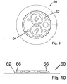
- Figures 9 and 10 show a second version 60, which is designed to carry two 3V cells 66, again placed on the top surface of the pcb 62.
- Version 2 can therefore drive one or more LEDs 64 that require a forward voltage drop of greater than 3V. This currently includes blue, white, ultra violet and jade green LEDs.
- the pcbs in both cases, are circular although they could be another shape e.g. square in order two fit a specific shape of bottle design.
- the thickness of the pcb can range from 0.4mm to 1.6mm.
- the pcb is appropriately as thin as possible as there is little height space available under a common 33cl bottle, for example.
- a rigid substrate pcb is used to ensure that the insertion of the cell(s) during assembly does not cause any significant warpage of the pcb, as this in itself can cause the pcb cell contact area, on the pcb surface, to be curved away from the cell and thus not make contact with the cell connection.
- the maximum area available on the pcb surface for connection to the cell is used in order to prevent disconnection occurring.
- the diameter around the cell contact area where there is no solder mask is larger than the diameter of the cell contact itself. This clearance around the cell contact area ensures that the cell is not lifted away from the contact area by the edges of the solder mask.
- the most common shape for the pcb is a circle, as most bottles are designed with a circular base.
- the pcb shape is not limited to a circle.
- a pcb diameter of 25-30mm is suitable.
- a pcb diameter of 35-40mm is suitable.
- Such devices use the direct application of LEDs 14, 54, 64, in un-packaged die form, to the pcb tracking. Although pre-packaged LEDs could be employed, this is generally a more costly approach and they are often bulkier so making them unsuitable for the small area under a bottle.
- the LED dies are bonded directly to the pcb 12, 52, 62 and protected by a quick-drying liquid resin.
- the application of this resin is carefully specified during assembly to ensure the resin is poured directly over the centre of the LED so the LED ends up positioned at the centre of the resin.
- the amount of resin poured on is also controlled to limit the overall height of each resin dome. This is important as the resin and LED combinations are generally positioned near the outer edges of the pcb and must not be so high as to prevent the device correctly fitting into the small space under a bottle. This is because the height available near the edges of the pcb is less than the height available near the centre of the pcb because the underside of a bottle is generally dome shaped.
- the type and wavelength of the LEDs are chosen depending on the colour of the container and the colour of the contents to be illuminated. They are also chosen depending on the colours required for the promotion by the client. More than one colour may be employed.
- the device can employ one or more LEDs.
- High intensity LEDs are generally used to overcome light absorption by coloured bottles and / or semi-opaque bottle content.
- an application on a 33cl beer bottle would use 3 or 4 LEDs.
- An application on a 75cl bottle would typically use between 4 and 6 LEDs.
- clear resin over the LEDs is used.
- a pre-packaged LED such as surface mounted LEDs or even larger pre-packaged LEDs, it is preferred that these have clear resin, so that the colour of the emitted light cannot easily be determined until after activation has occurred. This is particularly relevant where this system is employed for a promotional competition (for example, a limited number of "winning" containers may emit a different colour to regular containers).
- the circuitry of the integrated circuit package 18 is selected or a bespoke circuit is designed according to the specific requirements of the client.
- a client wants a circuit that will make the illumination permanently on until the cells are exhausted or flash or fade the LEDs in some way.
- the design also takes into account the length of time the illumination is to last for. Typically for a device for a beer bottle this would be greater than 30 minutes but less than one hour. For applications on larger sized spirits bottles the devices can be designed to last for hours, days or weeks depending on the clients requirements.
- mass manufactured ICs are employed in order to keep the cost low.
- the ICs are generally in die form and are bonded directly to the pcb tracking. Thereafter the ICs are covered in a protective resin. The amount of resin is also controlled during manufacture to ensure the height of this resin does not exceed the height limitations.
- the cell clips 20 are commonly plated copper, but can be made from plated steel or other conducting material.
- the cells require two-connections to them. One connection is made by direct contact to the pcb tracking; the other connection is made by means of a respective cell clip 20.
- the clip also has the function of retaining the cell in the correct position for continued operation. Cell holders, which would otherwise be required, can be large and bulky and costly.
- the device uses clips formed from pressed sheet metal instead of cell holders. These cell clips have pins 71, which are placed into locating holes in the pcb, and large flatted areas either side of the pins to aid in manually positioning the clips parallel to the pcb. The clips are soldered or crimped into place. With the use of manual assembly, the ease of placement and positioning of the cell clip(s) is important.
- the amount of solder used here is also carefully controlled to ensure that there is no excess of solder around the clip or above the natural height of the clip.
- the solder 73 When the solder 73 is applied it can be allowed to flow across the whole width of the clip pin, see Fig. 12.
- Fig. 12 shows that the solder can naturally flow on the outside and the inside of the clip pin.
- the amount of solder on the inside of the clip pin must be carefully controlled in order to not have excessive amounts of solder that may make contact with the other cell connection.
- the solder should not be allowed to build up and grow above the height of the cell clip, as shown in Fig. 13 , since the overall height of the device must be well controlled.
- the basic clip 20 has three pins 71, the third pin also being the end stop.
- the clips 20 can be either set so they are facing and hence parallel but opposite to each other, or they can be set so they are rotated away from each other in opposite directions ( Fig. 14 ), or they can be rotated in the same direction.
- the clips 20 are very close to each other, rotating them can eliminate the possibility of the opposite clips or cells making accidental contact with each other.
- the reason the clips must be as close to one another as possible is to keep the diameter of the pcb as small as possible as the domed area under a bottle is very small - if the clips were spaced further apart the device would not fit properly under the bottle and the bottle could not be placed down flat on a surface (i.e. the bottle could wobble).
- Having the clips positioned close to one another also allows for the maximum possible surface area of glue on the PVC label to be employed in area 39 so that the device can be securely stuck to the bottle base.
- Cell clips are not always required as it is possible to use cells that have pins which can be soldered directly into the circuit.
- the cells 16, 56, 66 are chosen to match the size constraints that the device has to operate within (in other words the cells need to be extremely thin so as to allow the device to fit into the narrow recess in a bottle base) and also the current and voltage requirements for the circuit.
- standard red, green and yellow LEDs can be driven using a source of 3V or less whereas it is necessary to have a voltage greater than 3V to successfully drive blue, white, UV, jade green LEDs etc.
- the device uses lithium cells that provide 3V necessitating two cells to drive devices utilising for example blue, white, UV, jade green LEDs whereas only one cell is required to drive devices using for example standard red, green and yellow LEDs.
- the cell or cells have a natural current limit to them and so it is also often not necessary to employ current limiting techniques.
- the CR1212 is employed because of its shallow height and small diameter. Larger cells can be employed for larger devices under larger bottles, typically on motion sensitive devices for large size spirits or liquor bottles the cells used are CR1616.
- the cells are required to be cleaned and be free of any oxidants or contaminants on their surfaces; this is to further ensure that good quality connections are made.
- the pcb wall connection may be plated, as with the process of through-hole plating in the manufacture of the pcb, or may have an additional contact placed over the pcb edge to connect to the cell. This approach further reduces the overall height of the device. It also eliminates the requirement for the cell clips as covered earlier.
- pull-tab 22 For the material of pull-tab 22, PVC is commonly used.
- the purpose of a pull-tab is to insulate and disconnect the power source 16, 56, 66 from the circuitry to prevent any power drain or activation occurring prior to intended use.
- the pull-tab ideally should be less than 0.05mm thick.
- the pull-tab can be removed from the side of the device that is not stuck down to the bottle base through a slit that is cut through the pad and the pcb that the pull-tab passes through.
- the advantage of this approach is that the device 10 can be stuck to the bottle and then at a later time the tab 22 can be removed to activate the device. So for the purposes of a large scale promotion, thousands of bottles (for example) can have devices stuck to them at a bottling plant or warehouse, the bottles can then be transported to multiple locations and stored, and some time in the future when the promotion begins, the tab can be removed to activate the device.
- the pull tab may be removed from directly under the cell prior to the device being stuck down to the bottle.
- the device cell clips 71 (which hold the cells onto the pcb and provide connections) have a butt or stop on one side, but are open ended on the other side.
- the reason for having one side that is open ended is to facilitate the insertion of the cells by hand into the cell clip during manufacture.
- a pull tab would be placed under a cell and be protruding from its outermost edge. This would not work well in this instance as it would tend to pull out the cell from the cell clip because the outermost edge of the cell clip is open. In the case of this application therefore, the pull tab is positioned so it pulls the cell into the centre of the device and thus into the butt or stop of the cell clip.
- the pull tab either passes up from the underside of the pad through a slit in the pad, then through a slit in the pcb, then over the pcb edge to its position under the cell, or if there is no appropriate slit, it is positioned directly under the cell such that its removal pulls the cell more firmly against the butt or stop of the cell clip.
- the slit in the pcb for the pull-tab to pass through can be about 0.5mm wide and 7mm long.
- Fig. 15 shows the slit or slot 81 in the pcb 12. through which the pull-tab is passed. The pull-tab passes through the pcb from underneath and is placed between the cell and the pcb. In Fig. 15 , the cell 16 on the left has the pull-tab beneath it.
- the pull tab acts as a single activation step i.e. once removed the device activates. In other instances the pull tab forms part of a two stage (or other multiple-stage) activation step. An example of a 2 stage application step would be the activation of the motion sensitive device.
- the pull tab once removed allows the motion sensitive switch to act as the actual trigger. Prior to the pull tab being removed the motion sensitive switch cannot activate.
- the material of the pull-tab is chosen to be an insulating plastic of 0.05mm thickness or less. The material does not stretch, when the tab is pulled. The thickness of the tab is also important to ensure that during its life under a cell it does not cause the cell clip to be deformed, which may otherwise result in the clip becoming loose around the cell after the pull-tab has been removed.
- the pull-tab can be manufactured to a customer specified length and can be of a customer specified colour to match any design tailoring requirements. It may also be printed on.
- FIG. 16 An alternative (or as one stage of a two stage method) of activation to the pull-tab 22 is the use of a tact switch arrangement as shown in Fig. 16 .
- the overall height of the switch is about 0.2 to 0.4mm, but still allows a positive action feel.
- a complete housed commercial tact switch is too bulky for this application, thus only the domed contact part 90 is employed.
- An additional advantage to using only the domed contact element is the reduced cost.
- This domed contact is positioned onto the pcb 12 directly. When the dome is pressed it connects tracks on the pcb at its outer edge to a pcb track under its centre. Thus a switch is completed.
- This domed contact can be attached to the pcb by adhesive tape which is a very low cost method, or by soldering or other method.
- adhesive tape which is a very low cost method, or by soldering or other method.
- the domed contact element may be surface mounted rather than through-hole mounted. Contact points 91 for the arrangement are shown.
- the domed contact element is preferably of stainless steel.
- the standard shape of the device is circular, it is not restricted to this exact shape. However, in practice is it simpler to manufacture using a circular pcb and this provides a larger pcb area for tracking and LED placement than a smaller oval or elliptical shape. Positioning the LEDs on the pcb nearer to the outer limits of the pcb has often proved to provide better visual impact of the illumination. If the pcb were not circular, but was still being used on a circular bottle, the LED placements may not be ideal. In addition, providing a circular device for placement onto a circular bottle base allows the user to more readily position the device in its optimum position.
- the overall shape of the device has been specifically designed to ensure that no modifications to the container it is fitted to are required, making the device suitable for use on any standard container be it fabricated from glass, plastic or metal or other types of material. This means that the device can be applied after manufacture of the bottle and does not have to be an integral part of the bottle manufacturing or bottle filling process.
- pcb and an adhesive pad in a circular shape results in a device, which can be easily glued to a curved glass or plastic or metal area. Once the device has been glued in place it is sealed around its outer edges from the ingress of moisture from the surrounding environment. This is important for applications on for example, beer bottles, where it is commonplace to fully immerse the bottle into iced water.
- the slit for the pull-tab (if used) is a very small area and does not allow further ingress of moisture because of the contained air pocket between the device and the container.
- an overall encapsulation for example encasing it in a moulded plastic, to seal the device substantially from the environment, although possible, would still lead to difficulties in activation (as it would still be necessary to have at least one hole for a pull-tab for example) and even greater difficulties in containing the whole device (including an encapsulation) within the restricted area of the small curve under a 33cl bottle.
- the device can be manufactured to comply with the recycling and restricted substances specifications of different countries.
- Such devices may be designed to be used until their cell power is exhausted and be thereafter disposable. So for example on a beer bottle application the devices are designed to last for approximately one hour. A motion sensitive device for a larger sized spirit bottle is designed to last for several days or longer. However the devices could be reused by renewing the cells and if necessary applying a fresh pad.
- the activation method commonly involves the closing of a circuit. This may be the closing of one or more circuit parts.
- using the removal of a pull-tab as the only activation method may be implemented by allowing a cell contact to connect to the circuit as the pull-tab is removed.
- the removal of a pull-tab to allow connection of the power source to the circuit is preferred as the first stage, and thereafter a standard circuit trigger input can be triggered by the use of different sensors, with or without an interface circuit to such a trigger input.
- Such sensors may include motion sensors such as inertial switches, vibration sensors such as piezo elements, temperature sensors such as PTCs, NTCs or infrared detectors, magnetic sensors such as hall-effect devices, light sensors for detecting changes in ambient light levels, wireless sensors such as radio frequency receivers, electromagnetic sensors such as LDRs or photo-diodes, sound sensors such as electret condenser microphones such that the light emission may be synchronised with music, moisture sensors, proximity sensors, pressure sensors, manual switching, direct circuit interfacing, etc. If a sensor is available or becomes available, which is of a suitable physical size then implementation into the device becomes possible.
- an initial activating event for example, removal of a pull-tab
- a secondary activating event for example, the bottle reaching a suitable temperature for consumption. This would prevent unintended activation, say, during transit or storage of the product.
- the illumination effect can be made time variable so the effect lasts for or starts after a specified period of time or after specified conditions have occurred.
- the device may be applied to articles other than containers.
- it can be applied to a substrate to form a self-contained badge capable of illumination.
Landscapes
- Engineering & Computer Science (AREA)
- Mechanical Engineering (AREA)
- Details Of Rigid Or Semi-Rigid Containers (AREA)
- Packages (AREA)
- Packaging Frangible Articles (AREA)
Claims (15)
- Eigenständige Beleuchtungsvorrichtung (10) zur Befestigung an einem Behälter, aufweisend eine Grundplatte (11) mit daran befestigten elektrischen Bauteilen (14, 16, 18) der Beleuchtungsvorrichtung, dadurch gekennzeichnet, dass die Grundplatte aus einem flüssigkeitsundurchlässigen Material ist, dass die elektrischen Elemente auf einer steifen Schaltungsplatine (12) vorgesehen sind, die an einem zentralen Abschnitt einer Hauptoberfläche der Grundplatte befestigt ist, und dass der zentrale Abschnitt umgeben ist von einem klebenden Abschnitt der Hauptoberfläche, wodurch die Grundplatte auf wasserdichte Weise an einen Behälter geklebt werden kann.
- Vorrichtung gemäß Anspruch 1, wobei die Grundplatte (11) flexibel ist.
- Vorrichtung gemäß Anspruch 2, wobei die Grundplatte aus einem Kunststoffmaterial oder einem plastifizierten Papiermaterial gemacht ist.
- Vorrichtung gemäß einem der vorangehenden Ansprüche, wobei die Grundplatte (11) eine erste Lage (32) aufweist, auf der die Schaltungsplatine befestigt ist, und eine ringförmige zweite Lage (36), welche den klebenden Abschnitt abdeckt und ablösbar an diesem befestigt ist.
- Vorrichtung gemäß Anspruch 4, wobei sich eine Trennungslinie (42) über die zweite Lage (36, 39) vom inneren Rand des Rings zum äußeren Rand des Rings erstreckt.
- Vorrichtung gemäß Anspruch 4 oder 5, wobei die erste Lage (32) einen biologisch abbaubaren Kunststoff und/oder Papiermaterial aufweist.
- Vorrichtung gemäß einem der Ansprüche 4 bis 6, wobei das Material der ersten Lage (32) stärker ist als das Material der zweiten Lage (36).
- Vorrichtung gemäß einem der vorangehenden Ansprüche, wobei die Dicke der Grundplatte (11) im Bereich von 0,15 bis 0,4 mm liegt.
- Vorrichtung gemäß einem der vorangehenden Ansprüche, wobei der klebende Abschnitt einen Klebstoff aufweist, dessen Versagen bei einer Temperatur über 80°C bei hoher Feuchtigkeit eintritt.
- Vorrichtung gemäß einem der vorangehenden Ansprüche, wobei die elektrischen Bauteile eine oder mehrere Lichtquellen (14) und eine oder mehrere Batteriezellen (16) aufweist.
- Vorrichtung gemäß Anspruch 10, wobei die oder jede Lichtquelle eine LED ist.
- Vorrichtung gemäß einem der Ansprüche 10 oder 11, wobei Zellen-Klammern (20) für die oder jede Batteriezelle (16) ebenfalls auf der Schaltungsplatine (12) vorgesehen sind.
- Vorrichtung gemäß einem der vorangehenden Ansprüche, welche ein Stück Isoliermaterial (22) aufweist, das in einer Position angeordnet ist, in der es elektrischen Kontakt einer Batteriezelle (16) mit anderen Schaltungselementen (14, 18) der Vorrichtung unterbindet, und über einen Spalt (81) durch die Schaltungsplatine und/oder einen Schlitz (44) durch die Grundplatte aus dieser Position bewegbar ist.
- Vorrichtung gemäß einem der vorangehenden Ansprüche, wobei die elektrischen Bauteile einen Schalter umfassen, der einen gewölbten Kontaktteil (90) aufweist.
- Verfahren zum Herstellen einer eigenständige Beleuchtungsvorrichtung (10), die zur Befestigung an einem Behälter geeignet ist, wobei das Verfahren folgendes aufweist:- Herstellen einer Grundplatte (11) mit einer ersten Lage (32) und einer ablösbar darauf geklebten zweiten Lage (36), wobei die zweite Lage eine erste Trennungslinie (40) besitzt, die eine innere Fläche (37) hiervon von einer umgebenden äußeren Fläche (39) trennt, und eine zweite Trennungslinie (42), die sich von der ersten Linie zum Rand der Grundplatte erstreckt,- Entfernen der inneren Fläche (37) der zweiten Lage und Befestigen einer steifen Schaltungsplatine (12) mit daran befestigten elektrischen Bauteilen (14, 16, 18) der Beleuchtungsvorrichtung an der so enthüllten Fläche der ersten Lage.
Priority Applications (2)
| Application Number | Priority Date | Filing Date | Title |
|---|---|---|---|
| SI200930292T SI2323912T2 (sl) | 2008-09-01 | 2009-09-01 | Priprava za osvetlitev vsebnika in postopek za njeno izdelavo |
| PL09785025T PL2323912T5 (pl) | 2008-09-01 | 2009-09-01 | Urządzenie oświetlające pojemnik i sposób jego wytwarzania |
Applications Claiming Priority (2)
| Application Number | Priority Date | Filing Date | Title |
|---|---|---|---|
| GBGB0815897.4A GB0815897D0 (en) | 2008-09-01 | 2008-09-01 | Container illumination device |
| PCT/GB2009/002097 WO2011007113A1 (en) | 2008-09-01 | 2009-09-01 | Container illumination device |
Publications (3)
| Publication Number | Publication Date |
|---|---|
| EP2323912A1 EP2323912A1 (de) | 2011-05-25 |
| EP2323912B1 true EP2323912B1 (de) | 2012-05-16 |
| EP2323912B2 EP2323912B2 (de) | 2015-08-19 |
Family
ID=39866065
Family Applications (1)
| Application Number | Title | Priority Date | Filing Date |
|---|---|---|---|
| EP09785025.9A Active EP2323912B2 (de) | 2008-09-01 | 2009-09-01 | Behälterbeleuchtungsvorrichtung und herstellungsverfahren dafür |
Country Status (11)
| Country | Link |
|---|---|
| US (1) | US8814379B2 (de) |
| EP (1) | EP2323912B2 (de) |
| CN (1) | CN102186733B (de) |
| AU (1) | AU2009349901B2 (de) |
| CA (1) | CA2735475C (de) |
| DK (1) | DK2323912T4 (de) |
| ES (1) | ES2386252T5 (de) |
| GB (1) | GB0815897D0 (de) |
| PL (1) | PL2323912T5 (de) |
| SI (1) | SI2323912T2 (de) |
| WO (1) | WO2011007113A1 (de) |
Families Citing this family (54)
| Publication number | Priority date | Publication date | Assignee | Title |
|---|---|---|---|---|
| US7967795B1 (en) | 2010-01-19 | 2011-06-28 | Lamodel Ltd. | Cartridge interface assembly with driving plunger |
| US9345836B2 (en) | 2007-10-02 | 2016-05-24 | Medimop Medical Projects Ltd. | Disengagement resistant telescoping assembly and unidirectional method of assembly for such |
| US10420880B2 (en) | 2007-10-02 | 2019-09-24 | West Pharma. Services IL, Ltd. | Key for securing components of a drug delivery system during assembly and/or transport and methods of using same |
| US9656019B2 (en) | 2007-10-02 | 2017-05-23 | Medimop Medical Projects Ltd. | Apparatuses for securing components of a drug delivery system during transport and methods of using same |
| JP5653217B2 (ja) | 2007-10-02 | 2015-01-14 | メディモップ メディカル プロジェクツ、エル・ティー・ディー | 外部薬剤ポンプ |
| US12097357B2 (en) | 2008-09-15 | 2024-09-24 | West Pharma. Services IL, Ltd. | Stabilized pen injector |
| US9393369B2 (en) | 2008-09-15 | 2016-07-19 | Medimop Medical Projects Ltd. | Stabilized pen injector |
| US10071196B2 (en) * | 2012-05-15 | 2018-09-11 | West Pharma. Services IL, Ltd. | Method for selectively powering a battery-operated drug-delivery device and device therefor |
| USD810278S1 (en) | 2009-09-15 | 2018-02-13 | Medimop Medical Projects Ltd. | Injector device |
| US8157769B2 (en) | 2009-09-15 | 2012-04-17 | Medimop Medical Projects Ltd. | Cartridge insertion assembly for drug delivery system |
| US10071198B2 (en) | 2012-11-02 | 2018-09-11 | West Pharma. Servicees IL, Ltd. | Adhesive structure for medical device |
| US8952629B2 (en) | 2009-12-11 | 2015-02-10 | Benmore Ventures Limited | Sound-actuated illumination circuit |
| CN102714905B (zh) | 2009-12-11 | 2015-11-25 | 永利有限公司 | 开关致动电路 |
| EP2510753A1 (de) | 2009-12-11 | 2012-10-17 | Benmore Ventures Limited | Schalterbetätigte anordnungen |
| US8348898B2 (en) | 2010-01-19 | 2013-01-08 | Medimop Medical Projects Ltd. | Automatic needle for drug pump |
| US9452261B2 (en) | 2010-05-10 | 2016-09-27 | Medimop Medical Projects Ltd. | Low volume accurate injector |
| USD702834S1 (en) | 2011-03-22 | 2014-04-15 | Medimop Medical Projects Ltd. | Cartridge for use in injection device |
| GB201108802D0 (en) | 2011-05-25 | 2011-07-06 | Benmore Ventures Ltd | Modular lighting systems |
| EP2568430A1 (de) | 2011-09-06 | 2013-03-13 | David Miller | Werbesystem und Verfahren auf Vertiefungsbasis |
| US9072827B2 (en) | 2012-03-26 | 2015-07-07 | Medimop Medical Projects Ltd. | Fail safe point protector for needle safety flap |
| GB2501745A (en) | 2012-05-03 | 2013-11-06 | Benmore Ventures Ltd | Disc for illuminating drinking vessels |
| US9421323B2 (en) | 2013-01-03 | 2016-08-23 | Medimop Medical Projects Ltd. | Door and doorstop for portable one use drug delivery apparatus |
| EP2979112B1 (de) * | 2013-03-28 | 2020-06-10 | Carrier Corporation | Verfolgungsvorrichtung |
| US9011164B2 (en) | 2013-04-30 | 2015-04-21 | Medimop Medical Projects Ltd. | Clip contact for easy installation of printed circuit board PCB |
| US10179694B2 (en) * | 2014-05-02 | 2019-01-15 | Thc Acquistion Corp. | Constant illuminated tamper-resistant plant shipping container |
| FR3031503A1 (fr) | 2015-01-14 | 2016-07-15 | Qualipac Sa | Recipient, composant de recipient, et gamme de tels produits |
| GB201503250D0 (en) * | 2015-02-26 | 2015-04-15 | Benmore Ventures Ltd | Illumination systems |
| US10293120B2 (en) | 2015-04-10 | 2019-05-21 | West Pharma. Services IL, Ltd. | Redundant injection device status indication |
| US10149943B2 (en) | 2015-05-29 | 2018-12-11 | West Pharma. Services IL, Ltd. | Linear rotation stabilizer for a telescoping syringe stopper driverdriving assembly |
| EP3302652B1 (de) | 2015-06-04 | 2023-09-06 | Medimop Medical Projects Ltd. | Kartuscheneinführung für arzneimittelabgavevorrichtung |
| US10576207B2 (en) | 2015-10-09 | 2020-03-03 | West Pharma. Services IL, Ltd. | Angled syringe patch injector |
| US9987432B2 (en) | 2015-09-22 | 2018-06-05 | West Pharma. Services IL, Ltd. | Rotation resistant friction adapter for plunger driver of drug delivery device |
| JP7017512B2 (ja) | 2015-10-09 | 2022-02-08 | ウェスト ファーマ サービシーズ イスラエル リミテッド | 充填済流体容器の屈曲流体路型付属物 |
| CN111544704B (zh) | 2016-01-21 | 2022-06-03 | 西医药服务以色列有限公司 | 自动注射器中的力牵制 |
| CN113041432B (zh) | 2016-01-21 | 2023-04-07 | 西医药服务以色列有限公司 | 包括视觉指示物的药剂输送装置 |
| US10646643B2 (en) | 2016-01-21 | 2020-05-12 | West Pharma. Services IL, Ltd. | Needle insertion and retraction mechanism |
| WO2017161076A1 (en) | 2016-03-16 | 2017-09-21 | Medimop Medical Projects Ltd. | Staged telescopic screw assembly having different visual indicators |
| US10415816B2 (en) | 2016-05-31 | 2019-09-17 | Light Up The World, Llc | Illuminated liquid vessel |
| EP4427776A3 (de) | 2016-06-02 | 2025-02-12 | West Pharma Services IL, Ltd | Nadelrückzug mit drei positionen |
| CN205807211U (zh) | 2016-06-20 | 2016-12-14 | 冯霞 | 用于容器的发光装置 |
| WO2018026387A1 (en) | 2016-08-01 | 2018-02-08 | Medimop Medical Projects Ltd. | Anti-rotation cartridge pin |
| CN109562220B (zh) | 2016-08-01 | 2021-06-29 | 西医药服务以色列有限公司 | 部分门关闭防止弹簧 |
| DE202016106373U1 (de) | 2016-11-14 | 2018-02-15 | königlich feiern GmbH | Beleuchtungsvorrichtung zur Beleuchtung eines Behältnisses |
| US11819666B2 (en) | 2017-05-30 | 2023-11-21 | West Pharma. Services IL, Ltd. | Modular drive train for wearable injector |
| EP3424837B1 (de) * | 2017-07-04 | 2019-09-18 | Chia-Shin Kuo | Leuchtender becherförmiger körper |
| US10386054B2 (en) | 2017-08-03 | 2019-08-20 | Sky Capital Technology Limited | Device, method, and system for illumination of bottle |
| US20190184272A1 (en) * | 2017-12-18 | 2019-06-20 | Jeffrey Cunningham | Enlightened Pong Game System and Method of Use |
| CN111683703B (zh) | 2017-12-22 | 2022-11-18 | 西氏医药包装(以色列)有限公司 | 适用于不同尺寸的药筒的注射器 |
| US11122921B2 (en) * | 2018-06-08 | 2021-09-21 | Nite Ize, Inc. | Systems and methods for an illuminating, drink insulating device |
| DE102018212965A1 (de) * | 2018-08-02 | 2020-02-06 | Vega Grieshaber Kg | Batteriebetriebene messvorichtung |
| US10874233B2 (en) | 2018-09-06 | 2020-12-29 | Joseph Luis Santiago | Decorative lighted cover for water jugs |
| US12117156B2 (en) * | 2022-05-27 | 2024-10-15 | Make It Better Llc | Attachable battery-powered light assembly for illuminating a bottle and method for illuminating a bottle with a light assembly |
| TR2024007748A1 (tr) * | 2024-06-13 | 2025-12-22 | Serdar Plastik Sanayi Ve Ticaret Anonim Sirketi | Led döner lamba |
| US12203608B1 (en) | 2024-09-27 | 2025-01-21 | Phillip R. Heberle | Illumination device |
Family Cites Families (53)
| Publication number | Priority date | Publication date | Assignee | Title |
|---|---|---|---|---|
| US5339548A (en) | 1992-08-26 | 1994-08-23 | Russell James M | Receptacle display activated after the sensing of the condition of the liquid |
| BE1006969A3 (fr) † | 1993-04-16 | 1995-02-07 | Collet Marcel Georges | Dessous-de-verre chimiluminescent. |
| CA2106528C (en) | 1993-09-20 | 1995-06-20 | Chris J. Maclean | Electronic bottle cap |
| US5464092A (en) | 1994-06-06 | 1995-11-07 | Seeley; Dennis H. | Container having an audible signaling device |
| JPH08140812A (ja) † | 1994-11-24 | 1996-06-04 | Hiroyuki Sugimoto | 光るコースター |
| EP0757012A4 (de) | 1995-03-06 | 1998-09-16 | Firm Vis Ltd | Behälter |
| EP0801517A3 (de) | 1995-07-14 | 1997-12-10 | Matsushita Electric Industrial Co., Ltd. | Beleuchteter Schalter |
| ES2147473B1 (es) | 1996-05-09 | 2001-03-16 | Customer Service S L | Sistema de marcado con elementos identificadores de procedencia. |
| DE29613520U1 (de) | 1996-08-05 | 1996-09-19 | Forschungszentrum Karlsruhe GmbH, 76133 Karlsruhe | Mikrooptischer Schalter |
| US5785407A (en) | 1996-11-18 | 1998-07-28 | Marpole International Inc. | Illuminable container |
| US6253247B1 (en) * | 1996-11-21 | 2001-06-26 | Ragula Systems | System and method for transmitting a user's data packets concurrently over different telephone lines between two computer networks |
| US6420008B1 (en) | 1997-01-28 | 2002-07-16 | Buztronics, Inc. | Display sticker with integral flasher circuit and power source |
| US5784265A (en) | 1997-05-19 | 1998-07-21 | Chen; Ken-Wang | Illuminating coaster |
| US5996781A (en) * | 1997-08-28 | 1999-12-07 | Glaser; Robert F. | Container having compartment for holding novelty article |
| FR2769596B1 (fr) | 1997-10-13 | 1999-12-10 | Gerard Previtali | Dispositif de decoration d'animation pour bouchons de bouteilles |
| KR200210798Y1 (ko) | 1998-03-06 | 2001-11-22 | 박경용 | 발광컵 |
| DE19852527A1 (de) | 1998-11-06 | 2000-05-11 | Bos Berlin Oberspree Sondermas | Siegel für ein verschließbares Gefäß oder Behältnis |
| US6254247B1 (en) | 1999-01-14 | 2001-07-03 | Redgate Industries, Inc. | Illuminable containers and method |
| WO2000055743A1 (en) | 1999-03-15 | 2000-09-21 | Add-Vision, Inc. | Electroluminescent interactive packaging display with sound |
| US6082866A (en) † | 1999-09-15 | 2000-07-04 | Amedee; Jacob L. | Illuminated coaster |
| US20080273319A1 (en) * | 1999-09-17 | 2008-11-06 | Vanderschuit Carl R | Beverage accessory devices |
| RU2186013C2 (ru) | 1999-12-14 | 2002-07-27 | Чернов Евгений Иванович | Затвор для сосудов |
| US6271753B1 (en) | 2000-03-21 | 2001-08-07 | Kavita M Shukla | Smart lid |
| US6419384B1 (en) | 2000-03-24 | 2002-07-16 | Buztronics Inc | Drinking vessel with indicator activated by inertial switch |
| RU2164888C1 (ru) | 2000-04-17 | 2001-04-10 | Ахметшин Равиль Миргасимович | Крышка для закрывания сосудов с горлышком |
| WO2001081823A2 (en) * | 2000-04-26 | 2001-11-01 | Gregory Edward Winters | Sleeve media holder |
| IT1318520B1 (it) | 2000-05-16 | 2003-08-27 | Henkel Spa | Contenitore per profumo con generatore di suoni o luce. |
| US6545594B1 (en) | 2000-05-25 | 2003-04-08 | The Coca-Cola Company | Audio closure |
| US6859745B2 (en) | 2001-05-18 | 2005-02-22 | Alcoa Closure Systems International | Interactive information package |
| WO2002099783A1 (en) | 2001-06-04 | 2002-12-12 | Andrzej Mroczkowski | Musical alcohol bottle cap |
| TW524240U (en) | 2001-07-26 | 2003-03-11 | Tai-Fa Lin | Audio cap |
| IL144749A (en) | 2001-08-06 | 2010-12-30 | Erez Brand | Food/drink container |
| US20040004829A1 (en) | 2001-09-07 | 2004-01-08 | Nini Policappelli | Illuminating, heating or cooling a consumer product |
| US20030076672A1 (en) † | 2001-10-23 | 2003-04-24 | Hayden Head | Illuminated drink holder |
| US6793362B2 (en) | 2001-10-26 | 2004-09-21 | Ti Hsien Tai | Flasher liquid container vessel |
| US20030095253A1 (en) | 2001-11-21 | 2003-05-22 | Chow Raymond Yiu Man | Container sensor system |
| DE10204153B4 (de) | 2002-02-01 | 2008-04-03 | Volker Omlor | Getränkbehältnis |
| US6746132B2 (en) | 2002-07-24 | 2004-06-08 | Pacific Cornetta, Inc. | Non-invasively actuated lighted drinking vessel and base unit |
| TWM240935U (en) | 2002-08-30 | 2004-08-21 | Haw Jong Co Ltd | Structure of luminous cup |
| US20040136177A1 (en) * | 2003-01-13 | 2004-07-15 | Lewis Edward D. | Ultraviolet illuminated fluorescent drinking vessel |
| TWM251744U (en) | 2003-01-21 | 2004-12-01 | Jia-Ping Liu | Illuminating modeling apparatus |
| US7080916B1 (en) * | 2003-05-23 | 2006-07-25 | Jim Mccafferty Productions, Inc. | Special effects drinking lid and straw |
| SI1636111T1 (en) | 2003-06-12 | 2018-08-31 | Benmore Ventures Limited | CONTRIBUTION WITH THE LIGHT GENERATOR |
| US20050024858A1 (en) | 2003-07-14 | 2005-02-03 | Richard Johnson | Container illumination |
| DE20312336U1 (de) | 2003-08-07 | 2004-02-26 | Drachenberg, Jens | Aufkleber mit Leuchtvorrichtung |
| GB2410487A (en) † | 2004-01-30 | 2005-08-03 | Andrew Neil Dwyer | Bottle illumination device |
| US20050207141A1 (en) * | 2004-03-22 | 2005-09-22 | Timothy Boesch | Drinking vessel |
| CN2776861Y (zh) * | 2005-01-26 | 2006-05-03 | 胡婷 | 发光容器 |
| US7976177B2 (en) | 2006-02-14 | 2011-07-12 | Leon Dikopf | Internally lighted bottle |
| FR2910990B1 (fr) | 2006-12-28 | 2009-06-12 | Neopost Technologies Sa | Enveloppe a slogan dynamique |
| AU2007100528A4 (en) † | 2007-05-30 | 2007-08-09 | Partridge, Corey Mr | Illuminant bottle |
| DE202007013731U1 (de) | 2007-10-01 | 2008-02-14 | Sun-Tec Swiss United Technologies Gmbh | Leuchtbehälter |
| US7687734B2 (en) * | 2008-06-19 | 2010-03-30 | Apple Inc. | Dome switch with integral actuator |
-
2008
- 2008-09-01 GB GBGB0815897.4A patent/GB0815897D0/en not_active Ceased
-
2009
- 2009-09-01 PL PL09785025T patent/PL2323912T5/pl unknown
- 2009-09-01 WO PCT/GB2009/002097 patent/WO2011007113A1/en not_active Ceased
- 2009-09-01 CN CN2009801411291A patent/CN102186733B/zh active Active
- 2009-09-01 ES ES09785025.9T patent/ES2386252T5/es active Active
- 2009-09-01 SI SI200930292T patent/SI2323912T2/sl unknown
- 2009-09-01 AU AU2009349901A patent/AU2009349901B2/en active Active
- 2009-09-01 US US13/061,597 patent/US8814379B2/en active Active
- 2009-09-01 CA CA2735475A patent/CA2735475C/en active Active
- 2009-09-01 EP EP09785025.9A patent/EP2323912B2/de active Active
- 2009-09-01 DK DK09785025.9T patent/DK2323912T4/en active
Also Published As
| Publication number | Publication date |
|---|---|
| EP2323912A1 (de) | 2011-05-25 |
| PL2323912T3 (pl) | 2012-09-28 |
| ES2386252T5 (es) | 2015-12-04 |
| US8814379B2 (en) | 2014-08-26 |
| AU2009349901A1 (en) | 2011-01-20 |
| AU2009349901A2 (en) | 2011-04-07 |
| SI2323912T2 (sl) | 2015-10-30 |
| WO2011007113A1 (en) | 2011-01-20 |
| SI2323912T1 (sl) | 2012-08-31 |
| DK2323912T3 (da) | 2012-08-13 |
| CN102186733A (zh) | 2011-09-14 |
| CA2735475C (en) | 2016-02-02 |
| EP2323912B2 (de) | 2015-08-19 |
| CA2735475A1 (en) | 2011-01-20 |
| ES2386252T3 (es) | 2012-08-14 |
| GB0815897D0 (en) | 2008-10-08 |
| CN102186733B (zh) | 2013-05-15 |
| PL2323912T5 (pl) | 2016-01-29 |
| DK2323912T4 (en) | 2015-11-30 |
| US20110188237A1 (en) | 2011-08-04 |
| AU2009349901B2 (en) | 2014-03-20 |
Similar Documents
| Publication | Publication Date | Title |
|---|---|---|
| EP2323912B1 (de) | Behälterbeleuchtungsvorrichtung und herstellungsverfahren dafür | |
| WO2010055312A1 (en) | Illumination devices for containers | |
| US20180360243A1 (en) | Illuminated Double Wall Lens Indicia Drinking Vessel | |
| US6857755B1 (en) | Illuminated bottle cap with epoxy dome | |
| US11348483B2 (en) | Linerless combined mailing label and return label and method of manufacturing same | |
| JP2000095272A (ja) | ストローおよびストロー付密封容器 | |
| US20190216246A1 (en) | Coaster for illuminating a liquid receptacle | |
| US20030224126A1 (en) | Decorative bow base adapted to be securely attached to a gift wrapping | |
| JP5912286B2 (ja) | 蓋部材、飲料容器 | |
| EP1533778A4 (de) | Biologisch abbaubares label für den formguss und biologisch abbaubarer behülter mit dem label daran haftend | |
| CA2517193A1 (en) | Removable portion of a label | |
| JP3194260U (ja) | ラベル | |
| US20250341305A1 (en) | Beverage container lights | |
| JP3577469B2 (ja) | 両面粘着部材保持構造体 | |
| JP2011073776A (ja) | インモールドラベル付き容器の蓋 | |
| CN217880651U (zh) | 一种局部无胶不干胶标签 | |
| JP3802924B2 (ja) | 蓋部が容易に開封可能な密封容器とその製造方法 | |
| JP3118065U (ja) | 固形洗浄剤包装容器 | |
| CN218768542U (zh) | 一种薄电池发光标签及其饮料瓶 | |
| KR200284490Y1 (ko) | 다수개의 컵이 겹쳐진 일회용 컵 | |
| JP2007168805A (ja) | シール容器 | |
| AU654783B1 (en) | Magnetic therapeutic appliance set | |
| JP3110108U (ja) | 画鋲 | |
| JP3147773U (ja) | 飲料容器用リッド | |
| CN205555038U (zh) | 一种方便食品包装体 |
Legal Events
| Date | Code | Title | Description |
|---|---|---|---|
| PUAI | Public reference made under article 153(3) epc to a published international application that has entered the european phase |
Free format text: ORIGINAL CODE: 0009012 |
|
| 17P | Request for examination filed |
Effective date: 20110304 |
|
| AK | Designated contracting states |
Kind code of ref document: A1 Designated state(s): AT BE BG CH CY CZ DE DK EE ES FI FR GB GR HR HU IE IS IT LI LT LU LV MC MK MT NL NO PL PT RO SE SI SK SM TR |
|
| AX | Request for extension of the european patent |
Extension state: AL BA RS |
|
| GRAP | Despatch of communication of intention to grant a patent |
Free format text: ORIGINAL CODE: EPIDOSNIGR1 |
|
| DAX | Request for extension of the european patent (deleted) | ||
| RTI1 | Title (correction) |
Free format text: CONTAINER ILLUMINATION DEVICE AND METHOD FOR ITS MANUFACTURING |
|
| GRAS | Grant fee paid |
Free format text: ORIGINAL CODE: EPIDOSNIGR3 |
|
| GRAA | (expected) grant |
Free format text: ORIGINAL CODE: 0009210 |
|
| AK | Designated contracting states |
Kind code of ref document: B1 Designated state(s): AT BE BG CH CY CZ DE DK EE ES FI FR GB GR HR HU IE IS IT LI LT LU LV MC MK MT NL NO PL PT RO SE SI SK SM TR |
|
| REG | Reference to a national code |
Ref country code: GB Ref legal event code: FG4D |
|
| REG | Reference to a national code |
Ref country code: CH Ref legal event code: EP |
|
| REG | Reference to a national code |
Ref country code: AT Ref legal event code: REF Ref document number: 557984 Country of ref document: AT Kind code of ref document: T Effective date: 20120615 |
|
| REG | Reference to a national code |
Ref country code: RO Ref legal event code: EPE |
|
| REG | Reference to a national code |
Ref country code: IE Ref legal event code: FG4D |
|
| REG | Reference to a national code |
Ref country code: CH Ref legal event code: NV Representative=s name: ISLER & PEDRAZZINI AG |
|
| REG | Reference to a national code |
Ref country code: DE Ref legal event code: R096 Ref document number: 602009007112 Country of ref document: DE Effective date: 20120719 |
|
| REG | Reference to a national code |
Ref country code: NL Ref legal event code: T3 |
|
| REG | Reference to a national code |
Ref country code: DK Ref legal event code: T3 |
|
| REG | Reference to a national code |
Ref country code: ES Ref legal event code: FG2A Ref document number: 2386252 Country of ref document: ES Kind code of ref document: T3 Effective date: 20120814 |
|
| REG | Reference to a national code |
Ref country code: SE Ref legal event code: TRGR |
|
| REG | Reference to a national code |
Ref country code: PL Ref legal event code: T3 |
|
| REG | Reference to a national code |
Ref country code: LT Ref legal event code: MG4D Effective date: 20120516 |
|
| REG | Reference to a national code |
Ref country code: GR Ref legal event code: EP Ref document number: 20120401732 Country of ref document: GR Effective date: 20120920 |
|
| PG25 | Lapsed in a contracting state [announced via postgrant information from national office to epo] |
Ref country code: CY Free format text: LAPSE BECAUSE OF FAILURE TO SUBMIT A TRANSLATION OF THE DESCRIPTION OR TO PAY THE FEE WITHIN THE PRESCRIBED TIME-LIMIT Effective date: 20120516 Ref country code: NO Free format text: LAPSE BECAUSE OF FAILURE TO SUBMIT A TRANSLATION OF THE DESCRIPTION OR TO PAY THE FEE WITHIN THE PRESCRIBED TIME-LIMIT Effective date: 20120816 Ref country code: LT Free format text: LAPSE BECAUSE OF FAILURE TO SUBMIT A TRANSLATION OF THE DESCRIPTION OR TO PAY THE FEE WITHIN THE PRESCRIBED TIME-LIMIT Effective date: 20120516 Ref country code: IS Free format text: LAPSE BECAUSE OF FAILURE TO SUBMIT A TRANSLATION OF THE DESCRIPTION OR TO PAY THE FEE WITHIN THE PRESCRIBED TIME-LIMIT Effective date: 20120916 |
|
| REG | Reference to a national code |
Ref country code: SK Ref legal event code: T3 Ref document number: E 12235 Country of ref document: SK |
|
| PG25 | Lapsed in a contracting state [announced via postgrant information from national office to epo] |
Ref country code: PT Free format text: LAPSE BECAUSE OF FAILURE TO SUBMIT A TRANSLATION OF THE DESCRIPTION OR TO PAY THE FEE WITHIN THE PRESCRIBED TIME-LIMIT Effective date: 20120917 Ref country code: HR Free format text: LAPSE BECAUSE OF FAILURE TO SUBMIT A TRANSLATION OF THE DESCRIPTION OR TO PAY THE FEE WITHIN THE PRESCRIBED TIME-LIMIT Effective date: 20120516 Ref country code: LV Free format text: LAPSE BECAUSE OF FAILURE TO SUBMIT A TRANSLATION OF THE DESCRIPTION OR TO PAY THE FEE WITHIN THE PRESCRIBED TIME-LIMIT Effective date: 20120516 |
|
| PG25 | Lapsed in a contracting state [announced via postgrant information from national office to epo] |
Ref country code: EE Free format text: LAPSE BECAUSE OF FAILURE TO SUBMIT A TRANSLATION OF THE DESCRIPTION OR TO PAY THE FEE WITHIN THE PRESCRIBED TIME-LIMIT Effective date: 20120516 |
|
| PLBI | Opposition filed |
Free format text: ORIGINAL CODE: 0009260 |
|
| PLAX | Notice of opposition and request to file observation + time limit sent |
Free format text: ORIGINAL CODE: EPIDOSNOBS2 |
|
| 26 | Opposition filed |
Opponent name: 2WF Effective date: 20130215 |
|
| PG25 | Lapsed in a contracting state [announced via postgrant information from national office to epo] |
Ref country code: MC Free format text: LAPSE BECAUSE OF NON-PAYMENT OF DUE FEES Effective date: 20120930 |
|
| REG | Reference to a national code |
Ref country code: DE Ref legal event code: R026 Ref document number: 602009007112 Country of ref document: DE Effective date: 20130215 |
|
| PLAF | Information modified related to communication of a notice of opposition and request to file observations + time limit |
Free format text: ORIGINAL CODE: EPIDOSCOBS2 |
|
| REG | Reference to a national code |
Ref country code: HU Ref legal event code: AG4A Ref document number: E015867 Country of ref document: HU |
|
| PG25 | Lapsed in a contracting state [announced via postgrant information from national office to epo] |
Ref country code: BG Free format text: LAPSE BECAUSE OF FAILURE TO SUBMIT A TRANSLATION OF THE DESCRIPTION OR TO PAY THE FEE WITHIN THE PRESCRIBED TIME-LIMIT Effective date: 20120816 |
|
| PLBB | Reply of patent proprietor to notice(s) of opposition received |
Free format text: ORIGINAL CODE: EPIDOSNOBS3 |
|
| PG25 | Lapsed in a contracting state [announced via postgrant information from national office to epo] |
Ref country code: MT Free format text: LAPSE BECAUSE OF FAILURE TO SUBMIT A TRANSLATION OF THE DESCRIPTION OR TO PAY THE FEE WITHIN THE PRESCRIBED TIME-LIMIT Effective date: 20120516 |
|
| PG25 | Lapsed in a contracting state [announced via postgrant information from national office to epo] |
Ref country code: LU Free format text: LAPSE BECAUSE OF NON-PAYMENT OF DUE FEES Effective date: 20120901 Ref country code: SM Free format text: LAPSE BECAUSE OF FAILURE TO SUBMIT A TRANSLATION OF THE DESCRIPTION OR TO PAY THE FEE WITHIN THE PRESCRIBED TIME-LIMIT Effective date: 20120516 |
|
| PLAB | Opposition data, opponent's data or that of the opponent's representative modified |
Free format text: ORIGINAL CODE: 0009299OPPO |
|
| R26 | Opposition filed (corrected) |
Opponent name: 2WF Effective date: 20130215 |
|
| PUAH | Patent maintained in amended form |
Free format text: ORIGINAL CODE: 0009272 |
|
| STAA | Information on the status of an ep patent application or granted ep patent |
Free format text: STATUS: PATENT MAINTAINED AS AMENDED |
|
| PG25 | Lapsed in a contracting state [announced via postgrant information from national office to epo] |
Ref country code: MK Free format text: LAPSE BECAUSE OF FAILURE TO SUBMIT A TRANSLATION OF THE DESCRIPTION OR TO PAY THE FEE WITHIN THE PRESCRIBED TIME-LIMIT Effective date: 20120516 |
|
| 27A | Patent maintained in amended form |
Effective date: 20150819 |
|
| AK | Designated contracting states |
Kind code of ref document: B2 Designated state(s): AT BE BG CH CY CZ DE DK EE ES FI FR GB GR HR HU IE IS IT LI LT LU LV MC MK MT NL NO PL PT RO SE SI SK SM TR |
|
| REG | Reference to a national code |
Ref country code: DE Ref legal event code: R102 Ref document number: 602009007112 Country of ref document: DE |
|
| REG | Reference to a national code |
Ref country code: CH Ref legal event code: AELC |
|
| REG | Reference to a national code |
Ref country code: DK Ref legal event code: T4 Effective date: 20151124 |
|
| REG | Reference to a national code |
Ref country code: SE Ref legal event code: RPEO |
|
| REG | Reference to a national code |
Ref country code: ES Ref legal event code: DC2A Ref document number: 2386252 Country of ref document: ES Kind code of ref document: T5 Effective date: 20151204 |
|
| REG | Reference to a national code |
Ref country code: GR Ref legal event code: EP Ref document number: 20150401996 Country of ref document: GR Effective date: 20151022 |
|
| REG | Reference to a national code |
Ref country code: NL Ref legal event code: FP |
|
| REG | Reference to a national code |
Ref country code: AT Ref legal event code: UEP Ref document number: 557984 Country of ref document: AT Kind code of ref document: T Effective date: 20150819 |
|
| REG | Reference to a national code |
Ref country code: SK Ref legal event code: T5 Ref document number: E 12235 Country of ref document: SK |
|
| REG | Reference to a national code |
Ref country code: FR Ref legal event code: PLFP Year of fee payment: 8 |
|
| REG | Reference to a national code |
Ref country code: FR Ref legal event code: PLFP Year of fee payment: 9 |
|
| REG | Reference to a national code |
Ref country code: FR Ref legal event code: PLFP Year of fee payment: 10 |
|
| REG | Reference to a national code |
Ref country code: GB Ref legal event code: 732E Free format text: REGISTERED BETWEEN 20230420 AND 20230426 |
|
| P01 | Opt-out of the competence of the unified patent court (upc) registered |
Effective date: 20230411 |
|
| PGFP | Annual fee paid to national office [announced via postgrant information from national office to epo] |
Ref country code: NL Payment date: 20230920 Year of fee payment: 15 Ref country code: IT Payment date: 20230915 Year of fee payment: 15 Ref country code: IE Payment date: 20230829 Year of fee payment: 15 Ref country code: GB Payment date: 20230830 Year of fee payment: 15 Ref country code: FI Payment date: 20230921 Year of fee payment: 15 Ref country code: AT Payment date: 20230913 Year of fee payment: 15 |
|
| PGFP | Annual fee paid to national office [announced via postgrant information from national office to epo] |
Ref country code: SE Payment date: 20230919 Year of fee payment: 15 Ref country code: GR Payment date: 20230830 Year of fee payment: 15 Ref country code: FR Payment date: 20230831 Year of fee payment: 15 Ref country code: DK Payment date: 20230929 Year of fee payment: 15 Ref country code: DE Payment date: 20230919 Year of fee payment: 15 Ref country code: BE Payment date: 20230925 Year of fee payment: 15 |
|
| PGFP | Annual fee paid to national office [announced via postgrant information from national office to epo] |
Ref country code: ES Payment date: 20231016 Year of fee payment: 15 |
|
| PGFP | Annual fee paid to national office [announced via postgrant information from national office to epo] |
Ref country code: CH Payment date: 20231001 Year of fee payment: 15 |
|
| PGFP | Annual fee paid to national office [announced via postgrant information from national office to epo] |
Ref country code: HU Payment date: 20250228 Year of fee payment: 16 |
|
| REG | Reference to a national code |
Ref country code: DE Ref legal event code: R119 Ref document number: 602009007112 Country of ref document: DE |
|
| PG25 | Lapsed in a contracting state [announced via postgrant information from national office to epo] |
Ref country code: FI Free format text: LAPSE BECAUSE OF NON-PAYMENT OF DUE FEES Effective date: 20240901 |
|
| PGFP | Annual fee paid to national office [announced via postgrant information from national office to epo] |
Ref country code: RO Payment date: 20250221 Year of fee payment: 16 |
|
| REG | Reference to a national code |
Ref country code: DK Ref legal event code: EBP Effective date: 20240930 |
|
| PGFP | Annual fee paid to national office [announced via postgrant information from national office to epo] |
Ref country code: SI Payment date: 20250224 Year of fee payment: 16 |
|
| PGFP | Annual fee paid to national office [announced via postgrant information from national office to epo] |
Ref country code: PL Payment date: 20250224 Year of fee payment: 16 Ref country code: CZ Payment date: 20250224 Year of fee payment: 16 |
|
| PGFP | Annual fee paid to national office [announced via postgrant information from national office to epo] |
Ref country code: SK Payment date: 20250221 Year of fee payment: 16 |
|
| REG | Reference to a national code |
Ref country code: SE Ref legal event code: EUG |
|
| PGFP | Annual fee paid to national office [announced via postgrant information from national office to epo] |
Ref country code: TR Payment date: 20250221 Year of fee payment: 16 |
|
| REG | Reference to a national code |
Ref country code: CH Ref legal event code: PL |
|
| REG | Reference to a national code |
Ref country code: NL Ref legal event code: MM Effective date: 20241001 |
|
| REG | Reference to a national code |
Ref country code: AT Ref legal event code: MM01 Ref document number: 557984 Country of ref document: AT Kind code of ref document: T Effective date: 20240901 |
|
| GBPC | Gb: european patent ceased through non-payment of renewal fee |
Effective date: 20240901 |
|
| PG25 | Lapsed in a contracting state [announced via postgrant information from national office to epo] |
Ref country code: NL Free format text: LAPSE BECAUSE OF NON-PAYMENT OF DUE FEES Effective date: 20241001 |
|
| PG25 | Lapsed in a contracting state [announced via postgrant information from national office to epo] |
Ref country code: DE Free format text: LAPSE BECAUSE OF NON-PAYMENT OF DUE FEES Effective date: 20250401 |
|
| PG25 | Lapsed in a contracting state [announced via postgrant information from national office to epo] |
Ref country code: GB Free format text: LAPSE BECAUSE OF NON-PAYMENT OF DUE FEES Effective date: 20240901 |
|
| REG | Reference to a national code |
Ref country code: BE Ref legal event code: MM Effective date: 20240930 |
|
| PG25 | Lapsed in a contracting state [announced via postgrant information from national office to epo] |
Ref country code: IT Free format text: LAPSE BECAUSE OF NON-PAYMENT OF DUE FEES Effective date: 20240901 Ref country code: BE Free format text: LAPSE BECAUSE OF NON-PAYMENT OF DUE FEES Effective date: 20240930 |
|
| PG25 | Lapsed in a contracting state [announced via postgrant information from national office to epo] |
Ref country code: FR Free format text: LAPSE BECAUSE OF NON-PAYMENT OF DUE FEES Effective date: 20240930 |
|
| PG25 | Lapsed in a contracting state [announced via postgrant information from national office to epo] |
Ref country code: GR Free format text: LAPSE BECAUSE OF NON-PAYMENT OF DUE FEES Effective date: 20250407 |
|
| PG25 | Lapsed in a contracting state [announced via postgrant information from national office to epo] |
Ref country code: CH Free format text: LAPSE BECAUSE OF NON-PAYMENT OF DUE FEES Effective date: 20240930 |
|
| PG25 | Lapsed in a contracting state [announced via postgrant information from national office to epo] |
Ref country code: AT Free format text: LAPSE BECAUSE OF NON-PAYMENT OF DUE FEES Effective date: 20240901 |
|
| PG25 | Lapsed in a contracting state [announced via postgrant information from national office to epo] |
Ref country code: IE Free format text: LAPSE BECAUSE OF NON-PAYMENT OF DUE FEES Effective date: 20240901 |
|
| PG25 | Lapsed in a contracting state [announced via postgrant information from national office to epo] |
Ref country code: DK Free format text: LAPSE BECAUSE OF NON-PAYMENT OF DUE FEES Effective date: 20240930 |
|
| PG25 | Lapsed in a contracting state [announced via postgrant information from national office to epo] |
Ref country code: SE Free format text: LAPSE BECAUSE OF NON-PAYMENT OF DUE FEES Effective date: 20240902 |
|
| REG | Reference to a national code |
Ref country code: ES Ref legal event code: FD2A Effective date: 20251024 |
|
| PG25 | Lapsed in a contracting state [announced via postgrant information from national office to epo] |
Ref country code: ES Free format text: LAPSE BECAUSE OF NON-PAYMENT OF DUE FEES Effective date: 20240902 |