EP2322698A1 - Procédé de fabrication d'un substrat de nitrure, et substrat de nitrure - Google Patents
Procédé de fabrication d'un substrat de nitrure, et substrat de nitrure Download PDFInfo
- Publication number
- EP2322698A1 EP2322698A1 EP09809936A EP09809936A EP2322698A1 EP 2322698 A1 EP2322698 A1 EP 2322698A1 EP 09809936 A EP09809936 A EP 09809936A EP 09809936 A EP09809936 A EP 09809936A EP 2322698 A1 EP2322698 A1 EP 2322698A1
- Authority
- EP
- European Patent Office
- Prior art keywords
- nitride
- front surface
- nitride substrate
- substrate
- angle
- Prior art date
- Legal status (The legal status is an assumption and is not a legal conclusion. Google has not performed a legal analysis and makes no representation as to the accuracy of the status listed.)
- Withdrawn
Links
Images


Classifications
-
- H—ELECTRICITY
- H01—ELECTRIC ELEMENTS
- H01L—SEMICONDUCTOR DEVICES NOT COVERED BY CLASS H10
- H01L21/00—Processes or apparatus adapted for the manufacture or treatment of semiconductor or solid state devices or of parts thereof
- H01L21/02—Manufacture or treatment of semiconductor devices or of parts thereof
- H01L21/02002—Preparing wafers
- H01L21/02005—Preparing bulk and homogeneous wafers
- H01L21/02008—Multistep processes
- H01L21/0201—Specific process step
- H01L21/02021—Edge treatment, chamfering
-
- C—CHEMISTRY; METALLURGY
- C30—CRYSTAL GROWTH
- C30B—SINGLE-CRYSTAL GROWTH; UNIDIRECTIONAL SOLIDIFICATION OF EUTECTIC MATERIAL OR UNIDIRECTIONAL DEMIXING OF EUTECTOID MATERIAL; REFINING BY ZONE-MELTING OF MATERIAL; PRODUCTION OF A HOMOGENEOUS POLYCRYSTALLINE MATERIAL WITH DEFINED STRUCTURE; SINGLE CRYSTALS OR HOMOGENEOUS POLYCRYSTALLINE MATERIAL WITH DEFINED STRUCTURE; AFTER-TREATMENT OF SINGLE CRYSTALS OR A HOMOGENEOUS POLYCRYSTALLINE MATERIAL WITH DEFINED STRUCTURE; APPARATUS THEREFOR
- C30B29/00—Single crystals or homogeneous polycrystalline material with defined structure characterised by the material or by their shape
- C30B29/10—Inorganic compounds or compositions
- C30B29/40—AIIIBV compounds wherein A is B, Al, Ga, In or Tl and B is N, P, As, Sb or Bi
- C30B29/403—AIII-nitrides
-
- C—CHEMISTRY; METALLURGY
- C30—CRYSTAL GROWTH
- C30B—SINGLE-CRYSTAL GROWTH; UNIDIRECTIONAL SOLIDIFICATION OF EUTECTIC MATERIAL OR UNIDIRECTIONAL DEMIXING OF EUTECTOID MATERIAL; REFINING BY ZONE-MELTING OF MATERIAL; PRODUCTION OF A HOMOGENEOUS POLYCRYSTALLINE MATERIAL WITH DEFINED STRUCTURE; SINGLE CRYSTALS OR HOMOGENEOUS POLYCRYSTALLINE MATERIAL WITH DEFINED STRUCTURE; AFTER-TREATMENT OF SINGLE CRYSTALS OR A HOMOGENEOUS POLYCRYSTALLINE MATERIAL WITH DEFINED STRUCTURE; APPARATUS THEREFOR
- C30B25/00—Single-crystal growth by chemical reaction of reactive gases, e.g. chemical vapour-deposition growth
-
- C—CHEMISTRY; METALLURGY
- C30—CRYSTAL GROWTH
- C30B—SINGLE-CRYSTAL GROWTH; UNIDIRECTIONAL SOLIDIFICATION OF EUTECTIC MATERIAL OR UNIDIRECTIONAL DEMIXING OF EUTECTOID MATERIAL; REFINING BY ZONE-MELTING OF MATERIAL; PRODUCTION OF A HOMOGENEOUS POLYCRYSTALLINE MATERIAL WITH DEFINED STRUCTURE; SINGLE CRYSTALS OR HOMOGENEOUS POLYCRYSTALLINE MATERIAL WITH DEFINED STRUCTURE; AFTER-TREATMENT OF SINGLE CRYSTALS OR A HOMOGENEOUS POLYCRYSTALLINE MATERIAL WITH DEFINED STRUCTURE; APPARATUS THEREFOR
- C30B29/00—Single crystals or homogeneous polycrystalline material with defined structure characterised by the material or by their shape
- C30B29/10—Inorganic compounds or compositions
- C30B29/40—AIIIBV compounds wherein A is B, Al, Ga, In or Tl and B is N, P, As, Sb or Bi
- C30B29/403—AIII-nitrides
- C30B29/406—Gallium nitride
-
- C—CHEMISTRY; METALLURGY
- C30—CRYSTAL GROWTH
- C30B—SINGLE-CRYSTAL GROWTH; UNIDIRECTIONAL SOLIDIFICATION OF EUTECTIC MATERIAL OR UNIDIRECTIONAL DEMIXING OF EUTECTOID MATERIAL; REFINING BY ZONE-MELTING OF MATERIAL; PRODUCTION OF A HOMOGENEOUS POLYCRYSTALLINE MATERIAL WITH DEFINED STRUCTURE; SINGLE CRYSTALS OR HOMOGENEOUS POLYCRYSTALLINE MATERIAL WITH DEFINED STRUCTURE; AFTER-TREATMENT OF SINGLE CRYSTALS OR A HOMOGENEOUS POLYCRYSTALLINE MATERIAL WITH DEFINED STRUCTURE; APPARATUS THEREFOR
- C30B33/00—After-treatment of single crystals or homogeneous polycrystalline material with defined structure
-
- H—ELECTRICITY
- H01—ELECTRIC ELEMENTS
- H01L—SEMICONDUCTOR DEVICES NOT COVERED BY CLASS H10
- H01L21/00—Processes or apparatus adapted for the manufacture or treatment of semiconductor or solid state devices or of parts thereof
- H01L21/02—Manufacture or treatment of semiconductor devices or of parts thereof
- H01L21/02002—Preparing wafers
- H01L21/02005—Preparing bulk and homogeneous wafers
- H01L21/02008—Multistep processes
- H01L21/0201—Specific process step
- H01L21/02013—Grinding, lapping
-
- H—ELECTRICITY
- H01—ELECTRIC ELEMENTS
- H01L—SEMICONDUCTOR DEVICES NOT COVERED BY CLASS H10
- H01L21/00—Processes or apparatus adapted for the manufacture or treatment of semiconductor or solid state devices or of parts thereof
- H01L21/02—Manufacture or treatment of semiconductor devices or of parts thereof
- H01L21/02104—Forming layers
- H01L21/02365—Forming inorganic semiconducting materials on a substrate
- H01L21/02367—Substrates
- H01L21/0237—Materials
- H01L21/02387—Group 13/15 materials
- H01L21/02389—Nitrides
Definitions
- the present invention relates to a method of manufacturing a nitride substrate, and a nitride substrate.
- An AlN (aluminum nitride) crystal has a wide energy band gap of 6.2 eV, a high thermal conductivity of about 3.3 WK -1 cm -1 , and a high electrical resistance.
- nitride crystals such as an AlN crystal have been attracting attention as materials for semiconductor devices such as optical devices and electronic devices.
- Patent Document 1 A method of manufacturing such a nitride crystal is disclosed, for example, in Japanese Patent Laying-Open No. 2007-197276 (Patent Document 1).
- a group III-V nitride semiconductor substrate is manufactured by the following steps. Specifically, a group III-V nitride semiconductor film is grown on a substrate of a different type having a c-plane or an off angle. Thereafter, a metal film is deposited on the substrate of a different type, and heat treatment is performed to form cavities in the group III-V nitride semiconductor film. Next, a group III-V nitride semiconductor crystal is deposited on the metal film.
- the substrate of a different type is delaminated to obtain a group III-V compound semiconductor crystal having a c-axis substantially vertical to a front surface or inclined by a predetermined angle with respect to the front surface.
- a rear surface of the group III-V nitride semiconductor crystal is polished to obtain a flat surface.
- a group III-V nitride semiconductor substrate is manufactured by removing the substrate of a different type, the group III-V nitride semiconductor film, and the metal film from the group III-V nitride semiconductor crystal.
- a semiconductor substrate made of the group III-V nitride semiconductor crystal manufactured as described above has an as-grown front surface.
- the group III-V nitride semiconductor crystal is grown in an as-grown state. That is, an off angle of the front surface of the group III-V nitride semiconductor substrate is controlled only by growth conditions of the group III-V nitride semiconductor crystal. Thus, it has been difficult to manufacture a group III-V nitride semiconductor substrate having a controlled off angle with a high yield.
- one object of the present invention is to provide a method of manufacturing a nitride substrate by which a nitride substrate having a controlled off angle of a front surface is manufactured with an improved yield, and the nitride substrate.
- a method of manufacturing a nitride substrate in one aspect of the present invention includes the following steps. Firstly, a nitride crystal is grown. Then, the nitride substrate including a front surface is cut from the nitride crystal. In the step of cutting, the nitride substrate is cut such that an off angle formed between an axis orthogonal to the front surface and an m-axis or an a-axis is greater than zero.
- the nitride substrate of the present invention is characterized in that, in the nitride substrate including the front surface, the off angle formed between the axis orthogonal to the front surface and the a-axis or the m-axis is greater than zero.
- the nitride substrate is cut from the nitride crystal to have an off angle in the entire front surface.
- the nitride substrate having a controlled off angle can be manufactured stably irrespective of the state of the grown nitride crystal (that is, without depending on growth conditions and the like of the nitride crystal).
- step growth as crystal growth in a lateral direction can be performed.
- the epitaxial layer can have good morphology, and thus crystallinity can be improved.
- nitride substrate including a front surface in which an off angle is controlled to form an epitaxial layer with high properties all over the nitride substrate can be manufactured with an improved yield.
- a method of manufacturing a nitride substrate in another aspect of the present invention includes the following steps. Firstly, a nitride crystal including a front surface and a rear surface opposite to the front surface is grown in a c-axis direction. Then, the nitride substrate is cut from the nitride crystal. In the step of cutting, the nitride substrate is cut from the nitride crystal along a flat plane which passes through the front surface and the rear surface of the nitride crystal and does not pass through a line segment connecting a center of a radius of curvature of the front surface with a center of a radius of curvature of the rear surface of the nitride crystal.
- a front surface of the nitride substrate includes a portion having an off angle of zero. Therefore, according to the method of manufacturing a nitride substrate in another aspect of the present invention, a nitride substrate in which an off angle formed between an axis orthogonal to a front surface and an ⁇ -axis or an m-axis is always controlled to be greater than zero can be manufactured.
- a nitride substrate having a controlled off angle can be manufactured stably irrespective of the state of the grown nitride crystal. Therefore, a nitride substrate in which an off angle is controlled to form an epitaxial layer with high properties can be manufactured with an improved yield.
- the nitride substrate is cut such that the nitride substrate includes the front surface having a first region and a second region surrounding the first region, and the off angle has a minimum value at a first point in the second region.
- the front surface has a first region and a second region surrounding the first region, and the off angle of the front surface has a minimum value at a first point in the second region.
- the off angle in the first region can be further increased, and thus step growth can be further enhanced when an epitaxial layer is formed on the nitride substrate.
- an epitaxial layer with higher properties can be formed on the first region located on an inner peripheral side.
- an outer peripheral side is generally less frequently used, and an inner peripheral side is generally more frequently used. Therefore, since properties in a more frequently used region in the substrate, device, and the like can be further improved, a nitride substrate in which an off angle is controlled to form an epitaxial layer with higher properties can be manufactured with an improved yield.
- the nitride substrate is cut such that the second region is within 2 mm from an edge of the nitride substrate. Further, preferably, in the nitride substrate described above, the second region is within 2 mm from an edge.
- the wide first region can be used for an epitaxial layer and the like with high properties.
- the nitride substrate is cut such that the off angle has a maximum value at a second point in the second region, and the off angle monotonically decreases from the second point to the first point.
- the off angle has a maximum value at a second point in the second region, and the off angle monotonically decreases from the second point to the first point.
- the off angle is not zero, and variations in the off angle can be suppressed.
- an epitaxial layer and the like with higher properties can be formed on the first region located on the inner peripheral side.
- the nitride substrate is cut from the nitride crystal along a flat plane parallel to a flat plane inclined from an a-plane or an m-plane in a c-axis direction.
- the front surface is inclined from an a-plane or an m-plane in a c-axis direction.
- the method of manufacturing a nitride substrate described above further includes the step of performing at least one of polishing and grinding of the front surface of the nitride substrate after the step of cutting.
- the front surface of the nitride substrate can be flattened.
- an epitaxial layer and the like can be produced easily using the nitride substrate.
- a plurality of the nitride substrates are cut. Thereby, manufacturing cost for each nitride substrate can be reduced.
- the nitride substrate by cutting the nitride substrate from the nitride crystal with the off angle being controlled, the nitride substrate can be manufactured with an improved yield such that the off angle formed between the axis orthogonal to the front surface and the m-axis or the a-axis is greater than zero.
- Fig. 1 is a perspective view schematically showing a nitride substrate in the present embodiment. Firstly, referring to Fig. 1 , the nitride substrate in the present embodiment will be described.
- a nitride substrate 10 includes a front surface 11.
- Front surface 11 has a first region 12 and a second region 13 surrounding the first region 12. That is, the first region 12 is located on an inner peripheral side in front surface 11 of nitride substrate 10, and the second region 13 is located on an outer peripheral side in front surface 11 of nitride substrate 10.
- the first region 12 in the present embodiment is a region in front surface 11 of nitride substrate 10 in which, of an epitaxial layer formed on front surface 11, an epitaxial layer used for a substrate or a device is formed.
- the second region 13 not used for a substrate or a device has a distance t of, for example, within 2 mm from an edge.
- Figs. 2 to 5 are schematic views showing off angles when the nitride substrate in the present embodiment is seen from above (a front surface side).
- an arrow is a vector indicating the magnitude and direction of an off angle.
- a represents an a-axis direction
- m represents an m-axis direction
- c represents an c-axis direction, indicating directions at a center of front surface 11 of nitride substrate 10.
- an off angle formed between an axis orthogonal to front surface 11 and an m-axis or an a-axis is greater than zero in entire front surface 11. That is, front surface 11 does not include a region where the off angle is zero.
- the off angle of front surface 11 may have the same magnitude as shown in Figs. 2 to 4 , or may have variations in magnitude as shown in Fig. 5 . Further, the direction of the off angle may be always constant as shown in Figs. 2 to 5 , or may be different (not shown).
- the off angle of front surface 11 has variations in magnitude as shown in Fig. 5
- the off angle has a minimum value at a first point 13a in the second region 13.
- the off angle has a maximum value at a second point 13b in the second region 13.
- the off angle monotonically decreases from the second point 13b to the first point 13a. It is to be noted that monotonic decrease means that the magnitude of the off angle is always identical or decreases from the second point 13b to the first point 13a, and the off angle at the first point 13a is smaller than the off angle at the second point 13b. That is, monotonic decrease does not include a portion in which the off angle increases from the second point 13b to the first point 13a.
- front surface 11 is inclined from an a-plane or an m-plane in the c-axis direction.
- a c-plane refers to a ⁇ 0001 ⁇ plane, including a (0001) plane, a (000-1) plane, and planes parallel thereto.
- the m-axis direction refers to a ⁇ 1-100> direction, including a [1-100] direction, a [10-10] direction, a [-1100] direction, a [-1010] direction, a [01-10] direction, and a [0-110] direction.
- the a-axis direction refers to a ⁇ 11-20> direction, including a [11-20] direction, a [1-210] direction, a [-2110] direction, a [-1-120] direction, a [-12-10] direction, and a [2-1-10] direction.
- the off angle in at least the first region 12 of front surface 11 is preferably not less than 0.15° and less than 2°, and more preferably not less than 0.3° and less than 0.7° within this range, an epitaxial layer with high properties can be formed on at least the first region 12.
- Nitride substrate 10 of the present embodiment has front surface 11 in the shape of a rectangular plate. If front surface 11 is rectangular, it is preferable that a maximum value of a distance between one point and another point on the edge of front surface 11 is not less than 5 mm. If front surface 11 is circular or elliptical, it is preferable that the longest diameter is not less than 10 mm.
- Nitride substrate 10 is, for example, In x Al y Ga (1-x-y) N (0 ⁇ x ⁇ 1, 0 ⁇ y ⁇ 1, 0 ⁇ x+y ⁇ 1), and preferably gallium nitride (GaN), AlN, AlGaN, or the like.
- GaN gallium nitride
- Figs. 6(A) and 6(B) are cross sectional views schematically showing a nitride crystal in the present embodiment.
- Fig. 7 is a growth apparatus capable of being used to manufacture the nitride crystal in the present embodiment.
- a nitride crystal 22 is grown.
- Nitride crystal 22 is an ingot for manufacturing nitride substrate 10.
- nitride crystal 22 is grown, for example, by a sublimation method.
- Growth apparatus 100 is an apparatus for growing a crystal by the sublimation method.
- growth apparatus 100 mainly includes a crucible 101, a heat body 121, a reaction vessel 123, and a heating portion 125.
- Crucible 101 is made of, for example, graphite.
- Crucible 101 has an air exhaust outlet 101a.
- Heat body 121 is provided around crucible 101 in a manner ensuring ventilation between an interior and an exterior of crucible 101.
- Reaction vessel 123 is provided around heat body 121.
- Heating portion 125 such as a high frequency heating coil for heating heat body 121 is provided at an outer central portion of reaction vessel 123.
- inlets 121a, 123 a for allowing a carrier gas such as nitrogen gas to flow into crucible 101 disposed within reaction vessel 123, and outlets 121b, 123b for emitting the carrier gas to an exterior of reaction vessel 123 are provided.
- radiation thermometers 127a, 127b for measuring temperatures above and below crucible 101 are provided.
- growth apparatus 100 described above may include various elements other than those described above, for convenience of explanation, these elements will not be shown and described.
- a base substrate 21 is prepared.
- the base substrate is not particularly limited, and may be a substrate of a different type such as an SiC (silicon carbide) substrate, or may be made of a material identical to that of nitride crystal 22 to be grown.
- an SiC substrate having a (0001) plane as a main surface is prepared as base substrate 21.
- Base substrate 21 is placed at an upper portion of crucible 101.
- a front surface of base substrate 21 is flattened, and a base substrate protection material made of, for example, graphite is placed on a rear surface side to closely adhere thereto to suppress sublimation of base substrate 21.
- raw material 17 is prepared. If an AlN crystal is grown as nitride crystal 22, for example, an AlN powder or the like is used as raw material 17.
- Raw material 17 is placed at a lower portion of crucible 101 to face base substrate 21 with each other.
- the temperature within crucible 101 is increased by heating heat body 121 using heating portion 125 while causing the nitrogen gas to flow into reaction vessel 123.
- raw material 17 is heated up to a temperature at which raw material 17 sublimates.
- raw material 17 sublimates and generates a sublimation gas.
- the sublimation gas is solidified again on the front surface of base substrate 21 set at a temperature lower than that of raw material 17.
- heating is performed such that, for example, base substrate 21 has a temperature of 2000°C and raw material 17 has a temperature of 2200°C, to grow a nitride crystal having a thickness of 30 ⁇ m, and the nitride crystal is further grown for 100 hours.
- a nitride crystal having a thickness of, for example, 10 mm can be grown. Thereafter, the nitride crystal is cooled down to a room temperature (for example, 25°C), and taken out from growth apparatus 100. Thereby, the nitride crystal can be grown on base substrate 21. Thereafter, raw material 17 is further replenished to further grow a nitride crystal on the nitride crystal. Thereby, as shown in Fig. 6(A) or 6(B) , nitride crystal 22 having a thickness of, for example, 19 mm is obtained. A front surface 22a of nitride crystal 22 is warped in a concave shape.
- a rear surface 22b of nitride crystal 22 may be warped. Warpages of front surface 22a and rear surface 22b may be identical as shown in Fig. 6(B) , or may be different as shown in Fig. 6(A) . It is to be noted that, as shown in Fig. 6(B) , base substrate 21 may sublimate due to the growth of nitride crystal 22.
- the method of growing nitride crystal 22 is not particularly limited to the sublimation method, and, for example, a vapor deposition method such an HVPE (Hydride Vapor Phase Epitaxy) method, an MBE (Molecular Beam Epitaxy) method, and an MOCVD (Metal Organic Chemical Vapor Deposition) method, a flux method, and a liquid phase method such as a high nitrogen pressure solution method can be employed.
- a vapor deposition method such an HVPE (Hydride Vapor Phase Epitaxy) method, an MBE (Molecular Beam Epitaxy) method, and an MOCVD (Metal Organic Chemical Vapor Deposition) method
- a flux method such as a high nitrogen pressure solution method
- a liquid phase method such as a high nitrogen pressure solution method
- nitride crystal 22 when nitride crystal 22 is grown by the HVPE method, it is grown, for example, as described below.
- base substrate 21 is prepared.
- a mask is formed on base substrate 21, and nitride crystal 22 is grown by the HVPE method.
- As nitride crystal 22, a GaN crystal having a thickness of, for example, 10 mm is grown.
- the base substrate is removed by etching with, for example, aqua regia. Thereby, nitride crystal 22 shown in Fig. 6(B) is obtained.
- Fig. 8 is a schematic plan view of the nitride crystal in the present embodiment seen from above.
- Figs. 9 and 10 are cross sectional views taken along a line IX-IX and a line X-X in Fig. 8 , and schematic views schematically showing crystal orientations of the nitride crystal.
- a dashed line indicates the c-axis direction, the a-axis direction, or the m-axis direction at each position.
- Front surface 22a of nitride crystal 22 grown as described above is warped in a concave shape as shown in Figs. 6(A), 6(B) , 9 , and 10 .
- nitride crystal 22 is grown in the c-axis direction, or front surface 22a, rear surface 22b, or an inside lattice plane of nitride crystal 22 is warped, an orientation of the c-axis, the a-axis, or the m-axis is different depending on a position in nitride crystal 22.
- nitride substrate 10 is cut from nitride crystal 22 in the present embodiment, nitride crystal 22 having a large thickness is grown as an ingot.
- front surface 22a of nitride crystal 22 is warped. Therefore, an off angle formed between front surface 22a of nitride crystal 22 and the a-axis or the m-axis varies depending on a position in front surface 22a. The same applies to rear surface 22b.
- difference in the orientation of the c-axis, the m-axis, or the a-axis for each position in front surface 22a of nitride crystal 22 is measured, for example, by an X-ray Diffraction (XRD) method. Measurement is similarly performed in rear surface 22b. In addition, measurement is similarly performed for the inside of nitride crystal 22, by exposing a location thereof.
- XRD X-ray Diffraction
- nitride substrate 10 including front surface 11 having the first region 12 and the second region 13 surrounding the first region 12 is cut from nitride crystal 22.
- nitride substrate 10 is cut such that the off angle formed between the axis orthogonal to front surface 11 and the m-axis or the a-axis is greater than zero.
- nitride substrate 10 is cut such that the off angle formed between the axis orthogonal to front surface 11 and the m-axis or the a-axis has a minimum value at the first point 13a in the second region 13. Further, it is preferable that nitride substrate 10 is cut such that the second region 13 is within 2 mm from an edge of nitride substrate 10. Furthermore, in the step of cutting, it is preferable that nitride substrate 10 is cut such that the off angle has a maximum value at the second point in the second region 13, and the off angle monotonically decreases from the second point 13b to the first point 13a.
- Fig. 11 is a cross sectional view showing nitride crystal 22 in the present embodiment.
- a represents the a-axis direction
- m represents the m-axis direction
- c represents the c-axis direction, indicating directions of the axes at a center of nitride crystal 22.
- nitride substrates 10 are cut from nitride crystal 22 along flat planes T1, T2 parallel to the m-plane at a center of front surface 22a as shown for example in Fig. 11 .
- Flat planes T1, T2 are not orthogonal to the m-axis of front surface 22a and rear surface 22b of nitride crystal 22. Front surfaces 11 of nitride substrates 10 cut along flat planes T1, T2 have off angles as shown in Figs. 2 and 3 , respectively. Since flat plane T2 has an inclination from the m-plane in the c-axis direction greater than that of flat plane T1, flat plane T2 has a greater off angle.
- Fig. 12 is another cross sectional view showing nitride crystal 22 in the present embodiment.
- a represents the a-axis direction
- m represents the m-axis direction
- c represents the c-axis direction, indicating the axes at the center of nitride crystal 22.
- nitride substrates 10 are cut from nitride crystal 22 along flat planes U1, U2 parallel to a flat plane inclined from the m-plane at the center of front surface 22a in the c-axis direction as shown for example in Fig. 12 .
- Flat planes U1, U2 are planes inclined from a direction in which the nitride crystal is grown (i.e., the c-axis direction at the center). In the present embodiment, flat planes U1,U2 are inclined by 0.2° from a flat plane vertical to the c-plane at the center of front surface 22a of nitride crystal 22. Flat planes U1, U2 are not orthogonal to the m-axis of front surface 22a and rear surface 22b of nitride crystal 22. Front surfaces 11 of nitride substrates 10 cut along flat planes U1, U2 have off angles as shown in Figs. 4 and 3 , respectively, and the orientations of the off angles are opposite to each other.
- Fig. 13 is another cross sectional view showing nitride crystal 22 in the present embodiment.
- a represents the a-axis direction
- m represents the m-axis direction
- c represents the c-axis direction, indicating directions of the axes at the center of front surface 22a of nitride crystal 22.
- m represents the m-axis direction
- c represents the c-axis direction, indicating directions of the axes at the center of front surface 22a of nitride crystal 22.
- nitride substrate 10 is cut from nitride crystal 22 along a flat plane W 1 which passes through front surface 22a and rear surface 22b of nitride crystal 22 and does not pass through centers of the radii of curvature of front surface 22a and rear surface 22b of nitride crystal 22 (a center O1 and a center 02) and therebetween (a line segment connecting center O1 with center O2). That is, flat plane W 1 is not orthogonal to the m-axis of front surface 22a and rear surface 22b of nitride crystal 22.
- flat plane W1 is not located between center O1 of the radius of curvature of front surface 22a and center 02 of the radius of curvature of rear surface 22b of nitride crystal 22. Namely, flat plane W1 is not orthogonal to the m-axis in entire nitride crystal 22. Front surface 11 of nitride substrate 10 cut along flat plane W1 has an off angle as shown in Fig. 5 .
- the "radii of curvature of front surface 22a and rear surface 22b” mean radii when curves of front surface 22a and rear surface 22b of nitride crystal 22 are approximated as arcs.
- the "center of the radius of curvature” means a center of the above approximated arc.
- nitride substrate 10 can be cut from nitride crystal 22 as shown in Figs. 11 to 13 .
- nitride substrate 10 is cut from nitride crystal 22 along a flat plane parallel to a flat plane inclined from the a-plane or the m-plane in the c-axis direction, such as flat planes U1, U2, W1.
- nitride substrate 10 is cut from nitride crystal 22 along a flat plane parallel to a flat plane inclined from the a-plane or the m-plane located at the center of nitride crystal 22 in the c-axis direction.
- the center of nitride crystal 22 means a center of a maximum length of diameters of circles inscribed in arbitrarily specified opposing two sides sandwiching a central portion in front surface 22a.
- the center of nitride crystal 22 means a center of a maximum length of diameters arbitrarily specified in front surface 22a.
- nitride crystal 22 has a size of, for example, not less than 10 mm, the plurality of nitride substrates 10 can be easily cut.
- a method of cutting nitride substrate 10 is not particularly limited, and for example, a mechanical method such as slicing can be used.
- Slicing refers to mechanically cutting nitride substrate 10 from nitride crystal 22 with a slicer having an outer peripheral cutting edge, a slicer having an inner peripheral cutting edge, a wire saw, or the like.
- Nitride substrate 10 manufactured as described above does not include a region where the off angle formed between the axis orthogonal to the front surface and the a-axis or the m-axis is zero.
- At least one of polishing and grinding of the front surface of nitride substrate 10 is performed as necessary. Grinding refers to grinding down the front surface in a thickness direction by bringing a rotating grindstone to be in contact with the front surface. Since particle detachment can be suppressed in nitride substrate 10 during polishing and grinding, front surface 11 can be easily flattened. It is to be noted that at least one of polishing and grinding of the rear surface of nitride substrate 10 may further be performed.
- nitride substrate 10 is shaped using a grindstone having diamond abrasive grains fixed thereto, and thereafter front surface 11 of nitride substrate 10 is ground or polished using diamond abrasive grains.
- a plurality of nitride substrates 10 having a thickness of, for example, 400 ⁇ m to 450 ⁇ m can be manufactured.
- nitride substrate 10 manufactured by the method of manufacturing nitride substrate 10 in the present embodiment will be described.
- nitride substrates 10 are cut from nitride crystal 22 along flat planes T1, T2 of Fig. 11 and flat planes U1, U2 of Fig. 12 not orthogonal to the m-axis and the a-axis of front surface 22a and rear surface 22b.
- nitride substrates 50 are cut from nitride crystal 22 along a flat plane T3 of Fig. 11 and a flat plane U3 of Fig. 12 in which at least one of front surface 22a and rear surface 22b is orthogonal to the m-axis or the a-axis. Since both front surface 22a and rear surface 22b are orthogonal to the m-axis or the a-axis in the case of the comparative example, an off angle is zero in an entire front surface 51 of nitride substrate 50 as shown in Fig. 14. Fig.
- FIG. 14 is a schematic view showing an off angle when the nitride substrate obtained in the comparative example is seen from a direction vertical to the front surface.
- a represents the a-axis direction
- m represents the m-axis direction
- c represents the c-axis direction, indicating directions at a center of front surface 51 of nitride substrate 50.
- No arrows are illustrated in Fig. 14 because the magnitude of the vector indicating the off angle is zero in the entire front surface 51 of nitride substrate 50.
- An epitaxial layer is formed on each of front surface 11 of nitride substrate 10 in the present embodiment and front surface 51 of nitride substrate 50 in the comparative example manufactured as described above. Since the epitaxial layer formed on a region having an off angle is crystal-grown in a lateral direction, the epitaxial layer grown on front surface 11 of nitride substrate 10 has good front surface morphology. That is, an epitaxial layer with high properties can be formed on nitride substrate 10 having front surface 11 in which the off angle is formed entirely as in the present embodiment. Thus, properties of a substrate, a device, and the like fabricated using the epitaxial layer can be improved in a wide range. Therefore, nitride substrate 10 in the present embodiment can control the off angle such that properties of the epitaxial layer formed on front surface 11 and a device using the same are improved.
- an epitaxial layer with high properties cannot be formed on a region where an off angle is zero. Therefore, the epitaxial layer grown on front surface 51 of nitride substrate 50 in the comparative example cannot obtain good morphology. That is, an epitaxial layer with high properties cannot be formed on nitride substrate 50 having front surface 51 in which the off angle is not formed entirely as in the comparative example. Thus, it is not possible to improve properties of a substrate, a device, and the like fabricated using the epitaxial layer. Therefore, nitride substrate 50 in the comparative example cannot control the off angle such that properties of the epitaxial layer formed on front surface 51 and a device using the same are improved.
- the inventors of the present invention have found that, when the nitride substrates are cut along flat planes W2, W3 which pass through centers O1 02 of the radii of curvature of front surface 22a and rear surface 22b of nitride crystal 22 as shown in Fig. 13 , the front surfaces of the cut nitride substrates have an off angle of zero.
- nitride substrate 10 is cut from nitride crystal 22 along flat plane W1 which passes through front surface 22a and rear surface 22b of nitride crystal 22 and does not pass through centers O1, 02 of the radii of curvature of front surface 22a and rear surface 22b of nitride crystal 22 (flat plane W1 which does not pass through the line segment connecting centers O1 and 02 of the radii of curvature) as shown in Fig. 13 .
- nitride substrate 10 in which the off angle formed between the axis orthogonal to the front surface and the m-axis or the a-axis is greater than zero as shown in Fig. 5 can be manufactured.
- nitride substrates 50 are cut from nitride crystal 22 along flat planes W2, W3 which pass through front surface 22a and rear surface 22b of nitride crystal 22 and pass through centers O1 02 of the radii of curvature of front surface 22a and rear surface 22b of nitride crystal 22.
- nitride substrates 50 each including a second region 53 having a first point 53a at which an off angle formed between an axis orthogonal to front surface 51 and the m-axis or the a-axis is zero, and a first region 52 located on an inner peripheral side of the second region 53 are manufactured as shown in Figs. 15 and 16 .
- FIGS. 15 and 16 are schematic views showing off angles when the nitride substrates obtained in the comparative example are seen from the direction vertical to the front surface.
- an arrow is a vector indicating the magnitude and direction of an off angle.
- a represents the a-axis direction
- m represents the m-axis direction
- c represents the c-axis direction, indicating directions at the center of front surface 51 of nitride substrate 50.
- nitride substrate 10 having an off angle with a minimum value at the first point 13a in the second region 13 can be manufactured when nitride substrate 10 is cut from nitride crystal 22 along flat plane W1 which does not pass the line segment connecting centers O1 and O2 of the radii of curvature of front surface 22a and rear surface 22b of nitride crystal 22 as shown in Fig. 13 .
- the epitaxial layer formed on the first region 12 located on the inner peripheral side on front surface 11 of nitride substrate 10 is used for a substrate, a device, and the like.
- the off angle of nitride substrate 10 is controlled such that the off angle in the second region 13 of nitride substrate 10 as a region not substantially used for a substrate, a device, and the like has a minimum value. Therefore, when an epitaxial layer is formed using nitride substrate 10 and used for a substrate, a device, and the like, the off angle can be controlled to further improve properties of a region to be used, that is, the first region 12.
- nitride substrate 10 is cut from nitride crystal 22 to have front surface 11 in which the off angle is controlled.
- nitride substrate 10 having a controlled off angle can be manufactured stably irrespective of the state of nitride crystal 22 (that is, without depending on growth conditions and the like of nitride crystal 22). Therefore, nitride substrate 10 in which the off angle is controlled to form an epitaxial layer with high properties can be manufactured with an improved yield.
- nitride crystal 22 When nitride crystal 22 is grown in the c-axis direction, nitride crystal 22 is generally warped in a concave shape with respect to the c-axis direction. In the present embodiment, in view of the warped shape, nitride substrate 10 is cut to control distribution of the off angle formed between the axis orthogonal to the front surface and the m-axis or the a-axis. Thus, nitride substrate 10 in which the off angle formed between the axis orthogonal to the front surface and the m-axis or the a-axis of the front surface is controlled can be manufactured with an improved yield.
- a slicing method in the step of cutting the nitride substrate from the nitride crystal such that the off angle formed between the axis orthogonal to the front surface and the m-axis or the a-axis is greater than zero was considered.
- Figs. 17 and 18 are schematic views of a nitride crystal with a diameter 2R having front surface 22a that can be approximated as a portion of an arc with a radius r and a center O (i.e., with r as a radius of curvature and O as the center of the radius of curvature), seen from substantially the a-axis direction.
- the thickness of the nitride crystal will be ignored for brevity.
- a method of cutting a nitride substrate in which an off angle from the m-plane is zero in the example shown in Fig. 17 will be considered.
- the nitride substrate is obtained, for example, by slicing a nitride crystal along a flat plane vertical to front surface 22a of the nitride crystal as represented by a flat plane V1.
- any plane having a portion common to the nitride crystal, of planes as represented by straight lines passing through center O falls under the above flat plane.
- the nitride substrate can be obtained by slicing the nitride crystal along a flat plane as represented by a flat plane V2 slightly deviated from center O.
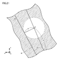
- Figs. 19 to 21 are schematic views for further considering sliced flat plane V2.
- the shape of the nitride crystal has been considered as a portion of the arc with radius r and center O in the example shown in Fig. 17 and in the example shown in Fig. 18
- the shape of the nitride crystal (front surface 22a) will be considered as an entire arc as shown in Figs. 20 and 21 .
- any plane with a distance of p from center O falls under flat plane V2.
- the distance from center O means a length of a perpendicular extending from center O to any plane.
- flat plane V2 for cutting the nitride substrate in which the off angle from the m-plane is ⁇ has the following two conditions:
- sliced flat plane V2 for obtaining the nitride substrate in which the off angle is ⁇ can be readily determined and sliced by measuring the position of center O, radius of curvature r, and diameter 2R of the nitride crystal in the case where front surface 22a of the nitride crystal is approximated as an arc, with X-ray diffraction, a ruler, a caliper, and the like, respectively.
- FIGS. 24 and 25 are schematic views for considering a sliced flat plane V3.
- flat plane V3 for cutting the nitride substrate in which the off angle from the m-plane is ⁇ 1 to ⁇ 2 has the following two conditions:
- sliced flat plane V3 for obtaining the nitride substrate in which the off angle is ⁇ 1 to ⁇ 2 can be readily determined and sliced by measuring the position of center O, radius of curvature r, and diameter 2R of the nitride crystal in the case where front surface 22a of the nitride crystal is approximated as an arc, with X-ray diffraction, a ruler, a caliper, and the like, respectively.
- Fig. 26 is a schematic view for considering a sliced flat plane V4.
- front surface 22a and rear surface 22b of a prepared nitride crystal are measured by X-ray diffraction, it is found that the nitride crystal has front surface 22a which can be approximated as a portion of an arc with a radius r1 and center O1, and rear surface 22b which can be approximated as a portion of an arc with a radius r2 and center O2.
- flat plane V4 for cutting a nitride substrate in which an off angle from the m-plane is ⁇ 1 to ⁇ 2 has the following three conditions:
- sliced flat plane V4 for obtaining the nitride substrate in which the off angle is ⁇ 1 to ⁇ 2 can be readily determined and sliced by measuring the positions of centers O1, 02, radii of curvature r1, r2, and diameter 2R of the nitride crystal in the case where front surface 22a and rear surface 22b of the nitride crystal are approximated as arcs, with X-ray diffraction, a ruler, a caliper, and the like, respectively.
- the c-plane other than the front surface and the rear surface of the nitride crystal can also be considered by increasing an arc with a center and a radius of curvature.
- the change in the radius of curvature in the growth thickness direction can be grasped more correctly, and distribution of the off angle within the sliced nitride substrate can be further improved.
- a sliced plane for obtaining a substrate having a controlled off angle can be determined with more accuracy by increasing an arc with a center and a radius of curvature for the c-plane other than the front surface and the rear surface and performing similar consideration.
- the center and the radius of curvature in the c-plane inside nitride crystal 22 can be measured by the X-ray Diffraction (XRD) method, for example by exposing a location thereof.
- Slicing Methods 1 to 3 can also be applied to a method of slicing a nitride substrate having an off angle with respect to the a-plane. That is, Slicing Methods 1 to 3 can be applied to a slicing method cutting a nitride substrate such that the off angle formed between the axis orthogonal to the front surface and the m-axis or the a-axis is greater than zero.
- a method of cutting a nitride substrate such that, with regard to the first region included in the front surface of the nitride substrate and the second region surrounding the first region, the second region is within 2 mm from the edge can also be considered similarly. That is, if the nitride substrate is sliced with coordinates of slicing points 1 and 2 specified in Example 2 described later being corrected, the nitride substrate can be cut such that the second region is within 2 mm from the edge.
- a concrete slicing method for cutting a nitride substrate from a grown nitride crystal such that the off angle formed between the axis orthogonal to the front surface and the m-axis or the a-axis is greater than zero was considered.
- a coordinate system fixed to a nitride crystal shown in Fig. 27 was defined to specify a slicing position.
- Fig. 27 is a schematic view for illustrating a method of designating a location for slicing a nitride crystal in the present example.
- a coordinate origin was set at a center of rear surface 22b of the nitride crystal
- a y-axis direction was set along the c-axis (i.e., the axis of rotational symmetry of the crystal)
- a z-axis direction was set in a direction in which a wire of a wire saw reciprocates.
- the a-axis (the m-axis) was oriented frontward (a z-direction). Slicing was performed using the wire to pass through two slicing points (slicing points 1, 2) designated by the coordinate system.
- the coordinates of slicing points 1 and 2 were set to (x1,y1), (x2,y2), respectively.
- the nitride crystal was inclined by a jig (not shown) such that a sliced plane was vertical.
- Cases 1 to 3 of the present invention and Comparative Example 1 below describe the details.
- Table 1 below describes manufacturing conditions and results of manufactured nitride substrates in Cases 1 to 3 of the present invention and Comparative Example 1.
- Case 1 of Present Invention Case 2 of Present Invention Case 3 of Present Invention Comparative Example 1 Nitride single crystal AlN GaN GaN AlN Radius of curvature on front surface side (m) 1.0 5.0 11.0 1.0 Radius of curvature on rear surface side (m) 1.1 5.5 10.5 1.1 Radius of crystal (mm) 25 37.5 50 25 Thickness at center of crystal (mm) 10 20 35 10 Coordinate (x,y) of slicing point 1 (mm) (8,1010) (19,5020) (211,11035) (0,1010) Coordinate (x,y) of slicing point 2 (mm) (10,1100) (22,5500) (202,10500) (0,1100) Substantial plane orientation of sliced substrate m m a m Number of sliced
- a 2-inch SiC substrate having a (0001) plane as a main surface was prepared, and an AlN single crystal was grown on the substrate as base substrate 21 by the sublimation method.
- base substrate 21 was placed at the upper portion of crucible 101 shown in Fig. 6 .
- a front surface of base substrate 21 was flattened, and a base substrate protection material made of graphite was placed on a rear surface side to closely adhere thereto to suppress sublimation of base substrate 21.
- an AlN powder raw material was prepared, and placed as raw material 17 at the lower portion of crucible 101 to face base substrate 21 with each other.
- the temperature within crucible 101 was increased by heating heat body 121 using heating portion 125 while causing the nitrogen gas to flow into reaction vessel 123. Heating was performed such that base substrate 21 had a temperature of 2000°C and raw material 17 had a temperature of 2200°C, to grow an AlN single crystal having a thickness of 30 ⁇ m, and the AlN single crystal was further grown for 100 hours. Thereafter, the AlN single crystal was cooled down to a room temperature, and the SiC substrate was removed. Thereby, an AlN single crystal as nitride crystal 22 having a growth thickness of about 10 mm in the c-axis direction was obtained.
- the AlN single crystal was set on a wire saw with a plane orientation thereof being checked, and sliced along a flat plane passing through slicing point 1 and slicing point 2 indicated in Table 1. Thereby, one AlN substrate was obtained.
- a 3-inch GaAs substrate having a (111) plane as a main surface was prepared, and an entire front surface of the GaAs substrate was covered with a thin mask.
- SiO 2 silicon dioxide
- a window was formed in the mask, and GaN was epitaxially grown through the window by the HVPE method.
- a Ga boat was provided at an upper portion inside the vertically long furnace, and a Ga melt was held therein.
- a susceptor was provided at a lower portion of the furnace, and the GaAs substrate was set thereon.
- a heater was provided around the furnace to heat the furnace.
- a mixed gas containing hydrogen gas and HCl gas was introduced from a gas inlet. HCl reacted with Ga to synthesize GaCl, and GaCl in the form of a gas flew downward.
- a mixed gas containing hydrogen gas and NH 3 gas was introduced from the gas inlet. GaCl reacted with NH 3 to synthesize GaN, and GaN was deposited on the GaAs substrate.
- a buffer layer was firstly grown at a low temperature (490°C), and thereafter the temperature was increased and epitaxial growth was performed at a high temperature (1010°C).
- a GaN single crystal having a thickness of 20 mm was grown as nitride crystal 22.
- the base substrate was removed by etching with aqua regia. Thereby, a GaN single crystal as nitride crystal 22 shown in Fig. 6(B) was obtained.
- wire slicing was performed along a flat plane passing through slicing points 1, 2 described in Table 1 to obtain two GaN substrates, and thus a GaN substrate of Case 2 of the present invention was manufactured. Since grinding and polishing were not performed after the slicing in Case 2 of the present invention, a front surface was not able to be flattened when compared with that in Case 1 of the present invention. However, an epitaxial layer was also able to be formed using the nitride substrate.
- the GaN substrate had a front surface which was substantially the m-plane and did not include an off angle of zero.
- a GaN single crystal grown in an HVPE furnace similar to that in Case 2 of the present invention was prepared. Similarly, it was confirmed that crystallinity in both a front surface and a rear surface of the obtained GaN single crystal was about 100 seconds, and warped shapes were also confirmed, using X-ray diffraction (see Table 1).
- the GaN single crystal was set on a wire saw with a direction thereof being changed from that in Case 2 of the present invention. Specifically, wire slicing was performed along a flat plane passing through slicing points 1, 2 described in Table 1 to obtain two substrates. After the slicing, grinding and polishing were performed as in Case 1 of the present invention. Thereby, a GaN substrate of Case 3 of the present invention was manufactured.
- the GaN substrate had a front surface which was substantially the a-plane and did not include an off angle of zero.
- nitride substrate 11, 22a: front surface, 12: first region, 13: second region, 13a: first point, 13b: second point, 17: raw material, 21: base substrate, 22: nitride crystal, 22b: rear surface, 100: growth apparatus, 101: crucible, 101a: air exhaust outlet, 121: heat body, 121a, 123a: inlet, 121b, 123b: outlet, 123: reaction vessel, 125: heating portion, 127a, 127b: radiation thermometer, T1, T2, T3, U1, U2, U3, W1, W2, W3, V1, V2, V3, V4: flat plane, O, O1 02: center.
Landscapes
- Chemical & Material Sciences (AREA)
- Engineering & Computer Science (AREA)
- Materials Engineering (AREA)
- Organic Chemistry (AREA)
- Crystallography & Structural Chemistry (AREA)
- Metallurgy (AREA)
- Inorganic Chemistry (AREA)
- Physics & Mathematics (AREA)
- Condensed Matter Physics & Semiconductors (AREA)
- General Physics & Mathematics (AREA)
- Manufacturing & Machinery (AREA)
- Computer Hardware Design (AREA)
- Microelectronics & Electronic Packaging (AREA)
- Power Engineering (AREA)
- General Chemical & Material Sciences (AREA)
- Chemical Kinetics & Catalysis (AREA)
- Crystals, And After-Treatments Of Crystals (AREA)
- Mechanical Treatment Of Semiconductor (AREA)
Applications Claiming Priority (2)
| Application Number | Priority Date | Filing Date | Title |
|---|---|---|---|
| JP2008223809 | 2008-09-01 | ||
| PCT/JP2009/064852 WO2010024285A1 (fr) | 2008-09-01 | 2009-08-26 | Procédé de fabrication d'un substrat de nitrure, et substrat de nitrure |
Publications (2)
| Publication Number | Publication Date |
|---|---|
| EP2322698A1 true EP2322698A1 (fr) | 2011-05-18 |
| EP2322698A4 EP2322698A4 (fr) | 2015-07-08 |
Family
ID=41721452
Family Applications (1)
| Application Number | Title | Priority Date | Filing Date |
|---|---|---|---|
| EP09809936.9A Withdrawn EP2322698A4 (fr) | 2008-09-01 | 2009-08-26 | Procédé de fabrication d'un substrat de nitrure, et substrat de nitrure |
Country Status (6)
| Country | Link |
|---|---|
| US (2) | US8829658B2 (fr) |
| EP (1) | EP2322698A4 (fr) |
| JP (2) | JPWO2010024285A1 (fr) |
| CN (1) | CN102137960B (fr) |
| TW (1) | TW201016905A (fr) |
| WO (1) | WO2010024285A1 (fr) |
Families Citing this family (3)
| Publication number | Priority date | Publication date | Assignee | Title |
|---|---|---|---|---|
| US9343525B2 (en) * | 2012-09-11 | 2016-05-17 | Tokuyama Corporation | Aluminum nitride substrate and group-III nitride laminate |
| US20200091016A1 (en) * | 2016-12-27 | 2020-03-19 | Sumitomo Chemical Company, Limited | Manufacturing method and inspection method of group-iii nitride laminate, and group-iii nitride laminate |
| KR20220118998A (ko) * | 2019-12-24 | 2022-08-26 | 가부시끼가이샤 도꾸야마 | Iii족 질화물 단결정 기판 및 그 제조 방법 |
Family Cites Families (16)
| Publication number | Priority date | Publication date | Assignee | Title |
|---|---|---|---|---|
| JPH10335750A (ja) | 1997-06-03 | 1998-12-18 | Sony Corp | 半導体基板および半導体装置 |
| US20110163323A1 (en) * | 1997-10-30 | 2011-07-07 | Sumitomo Electric Industires, Ltd. | GaN SINGLE CRYSTAL SUBSTRATE AND METHOD OF MAKING THE SAME |
| JP2005340747A (ja) * | 2003-11-04 | 2005-12-08 | Hitachi Cable Ltd | Iii−v族窒化物系半導体基板及びその製造方法、iii−v族窒化物系半導体デバイス、iii−v族窒化物系半導体基板のロット |
| US7118813B2 (en) | 2003-11-14 | 2006-10-10 | Cree, Inc. | Vicinal gallium nitride substrate for high quality homoepitaxy |
| JP4337560B2 (ja) * | 2004-01-22 | 2009-09-30 | 住友電気工業株式会社 | 単結晶窒化ガリウム基板を製造する方法、窒化ガリウム基板、および窒化物半導体エピタクシャル基板 |
| JP4581490B2 (ja) * | 2004-05-31 | 2010-11-17 | 日立電線株式会社 | Iii−v族窒化物系半導体自立基板の製造方法、及びiii−v族窒化物系半導体の製造方法 |
| JP4691911B2 (ja) * | 2004-06-11 | 2011-06-01 | 日立電線株式会社 | Iii−v族窒化物系半導体自立基板の製造方法 |
| JP4915128B2 (ja) * | 2005-04-11 | 2012-04-11 | 日亜化学工業株式会社 | 窒化物半導体ウエハ及びその製造方法 |
| JP4792802B2 (ja) * | 2005-04-26 | 2011-10-12 | 住友電気工業株式会社 | Iii族窒化物結晶の表面処理方法 |
| JP4696935B2 (ja) | 2006-01-27 | 2011-06-08 | 日立電線株式会社 | Iii−v族窒化物系半導体基板及びiii−v族窒化物系発光素子 |
| JP2007277053A (ja) | 2006-04-07 | 2007-10-25 | Sumitomo Electric Ind Ltd | 転位の検出方法、転位数の測定方法、転位密度の測定方法、GaN結晶基板および転位密度の算出方法 |
| KR100809209B1 (ko) | 2006-04-25 | 2008-02-29 | 삼성전기주식회사 | 비극성 m면 질화물 반도체 제조방법 |
| JP5129527B2 (ja) * | 2006-10-02 | 2013-01-30 | 株式会社リコー | 結晶製造方法及び基板製造方法 |
| JP5332168B2 (ja) | 2006-11-17 | 2013-11-06 | 住友電気工業株式会社 | Iii族窒化物結晶の製造方法 |
| JP2007189221A (ja) | 2006-12-21 | 2007-07-26 | Sharp Corp | 窒化物半導体基板、窒化物半導体レーザ素子、窒化物半導体基板の製造方法、および窒化物半導体レーザ素子の製造方法 |
| JP2008285364A (ja) * | 2007-05-17 | 2008-11-27 | Sumitomo Electric Ind Ltd | GaN基板、それを用いたエピタキシャル基板及び半導体発光素子 |
-
2009
- 2009-08-26 WO PCT/JP2009/064852 patent/WO2010024285A1/fr active Application Filing
- 2009-08-26 US US13/061,307 patent/US8829658B2/en not_active Expired - Fee Related
- 2009-08-26 JP JP2010526740A patent/JPWO2010024285A1/ja active Pending
- 2009-08-26 EP EP09809936.9A patent/EP2322698A4/fr not_active Withdrawn
- 2009-08-26 CN CN2009801341903A patent/CN102137960B/zh not_active Expired - Fee Related
- 2009-09-01 TW TW098129414A patent/TW201016905A/zh unknown
-
2014
- 2014-05-15 JP JP2014101578A patent/JP5812151B2/ja active Active
- 2014-08-18 US US14/461,838 patent/US20140357067A1/en not_active Abandoned
Non-Patent Citations (1)
| Title |
|---|
| See references of WO2010024285A1 * |
Also Published As
| Publication number | Publication date |
|---|---|
| US20110156213A1 (en) | 2011-06-30 |
| EP2322698A4 (fr) | 2015-07-08 |
| WO2010024285A1 (fr) | 2010-03-04 |
| CN102137960B (zh) | 2013-12-11 |
| JP5812151B2 (ja) | 2015-11-11 |
| JPWO2010024285A1 (ja) | 2012-01-26 |
| TW201016905A (en) | 2010-05-01 |
| JP2014141413A (ja) | 2014-08-07 |
| US20140357067A1 (en) | 2014-12-04 |
| CN102137960A (zh) | 2011-07-27 |
| US8829658B2 (en) | 2014-09-09 |
Similar Documents
| Publication | Publication Date | Title |
|---|---|---|
| JP5446622B2 (ja) | Iii族窒化物結晶およびその製造方法 | |
| JP5560528B2 (ja) | Iii族窒化物単結晶インゴットの製造方法、及びiii族窒化物単結晶基板の製造方法 | |
| JP7255817B2 (ja) | GaN結晶の製造方法 | |
| EP2063458A2 (fr) | Procédé de croissance de cristal semiconducteur à nitrure de groupe III, procédé de fabrication de substrats cristallins à nitrure de groupe III, et substrat cristallin à nitrure de groupe III | |
| KR101749781B1 (ko) | 단결정 기판, 이를 이용하여 얻어지는 ⅲ족 질화물 결정 및 ⅲ족 질화물 결정의 제조방법 | |
| JP4691911B2 (ja) | Iii−v族窒化物系半導体自立基板の製造方法 | |
| KR20100113529A (ko) | Ⅲ족 질화물 결정의 성장 방법 | |
| KR20060043770A (ko) | GaN 단결정 기판의 제조 방법 및 GaN 단결정 기판 | |
| JP6187576B2 (ja) | Iii族窒化物結晶 | |
| JP2007217227A (ja) | GaN結晶の製造方法、GaN結晶基板および半導体デバイス | |
| KR20110052569A (ko) | Ⅲ족 질화물 결정의 제조 방법 및 ⅲ족 질화물 결정 | |
| CN101440521A (zh) | 半导体晶体生长方法、半导体晶体基板及其制造方法 | |
| WO2007148615A1 (fr) | Procédé de croissance d'un cristal de AlxGa1-xN, et substrat en cristal de AlxGa1-xN | |
| US20140357067A1 (en) | Method of manufacturing nitride substrate, and nitride substrate | |
| JP5120285B2 (ja) | Iii−v族窒化物系半導体自立基板の製造方法 | |
| EP3951025A1 (fr) | Tranche de substrat de nitrure de gallium et procédé de fabrication de tranche de substrat de nitrure de gallium | |
| JP2010030799A (ja) | AlN基板の製造方法およびAlN基板 | |
| JP2013227208A (ja) | Iii族窒化物結晶およびiii族窒化物結晶基板 | |
| WO2023210696A1 (fr) | Substrat de gan de type n et cristal de gan de type n | |
| JP2013199412A (ja) | Iii族窒化物半導体結晶の製造方法 | |
| JP2019077602A (ja) | Iii族窒化物半導体基板及びiii族窒化物半導体基板の製造方法 |
Legal Events
| Date | Code | Title | Description |
|---|---|---|---|
| PUAI | Public reference made under article 153(3) epc to a published international application that has entered the european phase |
Free format text: ORIGINAL CODE: 0009012 |
|
| 17P | Request for examination filed |
Effective date: 20110307 |
|
| AK | Designated contracting states |
Kind code of ref document: A1 Designated state(s): AT BE BG CH CY CZ DE DK EE ES FI FR GB GR HR HU IE IS IT LI LT LU LV MC MK MT NL NO PL PT RO SE SI SK SM TR |
|
| AX | Request for extension of the european patent |
Extension state: AL BA RS |
|
| DAX | Request for extension of the european patent (deleted) | ||
| RIC1 | Information provided on ipc code assigned before grant |
Ipc: C30B 33/00 20060101ALI20141215BHEP Ipc: C30B 25/00 20060101ALI20141215BHEP Ipc: H01L 21/02 20060101ALI20141215BHEP Ipc: B24B 1/00 20060101ALI20141215BHEP Ipc: H01L 21/304 20060101ALI20141215BHEP Ipc: C30B 29/40 20060101AFI20141215BHEP |
|
| STAA | Information on the status of an ep patent application or granted ep patent |
Free format text: STATUS: THE APPLICATION HAS BEEN WITHDRAWN |
|
| RA4 | Supplementary search report drawn up and despatched (corrected) |
Effective date: 20150608 |
|
| RIC1 | Information provided on ipc code assigned before grant |
Ipc: C30B 25/00 20060101ALI20150601BHEP Ipc: C30B 29/40 20060101AFI20150601BHEP Ipc: C30B 33/00 20060101ALI20150601BHEP Ipc: H01L 21/304 20060101ALI20150601BHEP Ipc: B24B 1/00 20060101ALI20150601BHEP Ipc: H01L 21/02 20060101ALI20150601BHEP |
|
| 18W | Application withdrawn |
Effective date: 20150611 |