EP2320043A1 - Dispositif de contrôle d'émissions d'échappement d'un moteur à combustion interne - Google Patents
Dispositif de contrôle d'émissions d'échappement d'un moteur à combustion interne Download PDFInfo
- Publication number
- EP2320043A1 EP2320043A1 EP10197409A EP10197409A EP2320043A1 EP 2320043 A1 EP2320043 A1 EP 2320043A1 EP 10197409 A EP10197409 A EP 10197409A EP 10197409 A EP10197409 A EP 10197409A EP 2320043 A1 EP2320043 A1 EP 2320043A1
- Authority
- EP
- European Patent Office
- Prior art keywords
- value
- selective reduction
- reduction catalyst
- nox
- detection signal
- Prior art date
- Legal status (The legal status is an assumption and is not a legal conclusion. Google has not performed a legal analysis and makes no representation as to the accuracy of the status listed.)
- Granted
Links
Images


Classifications
-
- F—MECHANICAL ENGINEERING; LIGHTING; HEATING; WEAPONS; BLASTING
- F01—MACHINES OR ENGINES IN GENERAL; ENGINE PLANTS IN GENERAL; STEAM ENGINES
- F01N—GAS-FLOW SILENCERS OR EXHAUST APPARATUS FOR MACHINES OR ENGINES IN GENERAL; GAS-FLOW SILENCERS OR EXHAUST APPARATUS FOR INTERNAL COMBUSTION ENGINES
- F01N3/00—Exhaust or silencing apparatus having means for purifying, rendering innocuous, or otherwise treating exhaust
- F01N3/08—Exhaust or silencing apparatus having means for purifying, rendering innocuous, or otherwise treating exhaust for rendering innocuous
- F01N3/10—Exhaust or silencing apparatus having means for purifying, rendering innocuous, or otherwise treating exhaust for rendering innocuous by thermal or catalytic conversion of noxious components of exhaust
- F01N3/18—Exhaust or silencing apparatus having means for purifying, rendering innocuous, or otherwise treating exhaust for rendering innocuous by thermal or catalytic conversion of noxious components of exhaust characterised by methods of operation; Control
- F01N3/20—Exhaust or silencing apparatus having means for purifying, rendering innocuous, or otherwise treating exhaust for rendering innocuous by thermal or catalytic conversion of noxious components of exhaust characterised by methods of operation; Control specially adapted for catalytic conversion ; Methods of operation or control of catalytic converters
- F01N3/2066—Selective catalytic reduction [SCR]
- F01N3/208—Control of selective catalytic reduction [SCR], e.g. dosing of reducing agent
-
- F—MECHANICAL ENGINEERING; LIGHTING; HEATING; WEAPONS; BLASTING
- F01—MACHINES OR ENGINES IN GENERAL; ENGINE PLANTS IN GENERAL; STEAM ENGINES
- F01N—GAS-FLOW SILENCERS OR EXHAUST APPARATUS FOR MACHINES OR ENGINES IN GENERAL; GAS-FLOW SILENCERS OR EXHAUST APPARATUS FOR INTERNAL COMBUSTION ENGINES
- F01N11/00—Monitoring or diagnostic devices for exhaust-gas treatment apparatus, e.g. for catalytic activity
-
- F—MECHANICAL ENGINEERING; LIGHTING; HEATING; WEAPONS; BLASTING
- F01—MACHINES OR ENGINES IN GENERAL; ENGINE PLANTS IN GENERAL; STEAM ENGINES
- F01N—GAS-FLOW SILENCERS OR EXHAUST APPARATUS FOR MACHINES OR ENGINES IN GENERAL; GAS-FLOW SILENCERS OR EXHAUST APPARATUS FOR INTERNAL COMBUSTION ENGINES
- F01N9/00—Electrical control of exhaust gas treating apparatus
-
- F—MECHANICAL ENGINEERING; LIGHTING; HEATING; WEAPONS; BLASTING
- F01—MACHINES OR ENGINES IN GENERAL; ENGINE PLANTS IN GENERAL; STEAM ENGINES
- F01N—GAS-FLOW SILENCERS OR EXHAUST APPARATUS FOR MACHINES OR ENGINES IN GENERAL; GAS-FLOW SILENCERS OR EXHAUST APPARATUS FOR INTERNAL COMBUSTION ENGINES
- F01N2550/00—Monitoring or diagnosing the deterioration of exhaust systems
- F01N2550/02—Catalytic activity of catalytic converters
-
- F—MECHANICAL ENGINEERING; LIGHTING; HEATING; WEAPONS; BLASTING
- F01—MACHINES OR ENGINES IN GENERAL; ENGINE PLANTS IN GENERAL; STEAM ENGINES
- F01N—GAS-FLOW SILENCERS OR EXHAUST APPARATUS FOR MACHINES OR ENGINES IN GENERAL; GAS-FLOW SILENCERS OR EXHAUST APPARATUS FOR INTERNAL COMBUSTION ENGINES
- F01N2560/00—Exhaust systems with means for detecting or measuring exhaust gas components or characteristics
- F01N2560/02—Exhaust systems with means for detecting or measuring exhaust gas components or characteristics the means being an exhaust gas sensor
- F01N2560/021—Exhaust systems with means for detecting or measuring exhaust gas components or characteristics the means being an exhaust gas sensor for measuring or detecting ammonia NH3
-
- F—MECHANICAL ENGINEERING; LIGHTING; HEATING; WEAPONS; BLASTING
- F01—MACHINES OR ENGINES IN GENERAL; ENGINE PLANTS IN GENERAL; STEAM ENGINES
- F01N—GAS-FLOW SILENCERS OR EXHAUST APPARATUS FOR MACHINES OR ENGINES IN GENERAL; GAS-FLOW SILENCERS OR EXHAUST APPARATUS FOR INTERNAL COMBUSTION ENGINES
- F01N2560/00—Exhaust systems with means for detecting or measuring exhaust gas components or characteristics
- F01N2560/02—Exhaust systems with means for detecting or measuring exhaust gas components or characteristics the means being an exhaust gas sensor
- F01N2560/026—Exhaust systems with means for detecting or measuring exhaust gas components or characteristics the means being an exhaust gas sensor for measuring or detecting NOx
-
- F—MECHANICAL ENGINEERING; LIGHTING; HEATING; WEAPONS; BLASTING
- F01—MACHINES OR ENGINES IN GENERAL; ENGINE PLANTS IN GENERAL; STEAM ENGINES
- F01N—GAS-FLOW SILENCERS OR EXHAUST APPARATUS FOR MACHINES OR ENGINES IN GENERAL; GAS-FLOW SILENCERS OR EXHAUST APPARATUS FOR INTERNAL COMBUSTION ENGINES
- F01N2610/00—Adding substances to exhaust gases
- F01N2610/02—Adding substances to exhaust gases the substance being ammonia or urea
-
- F—MECHANICAL ENGINEERING; LIGHTING; HEATING; WEAPONS; BLASTING
- F01—MACHINES OR ENGINES IN GENERAL; ENGINE PLANTS IN GENERAL; STEAM ENGINES
- F01N—GAS-FLOW SILENCERS OR EXHAUST APPARATUS FOR MACHINES OR ENGINES IN GENERAL; GAS-FLOW SILENCERS OR EXHAUST APPARATUS FOR INTERNAL COMBUSTION ENGINES
- F01N2900/00—Details of electrical control or of the monitoring of the exhaust gas treating apparatus
- F01N2900/04—Methods of control or diagnosing
- F01N2900/0404—Methods of control or diagnosing using a data filter
-
- F—MECHANICAL ENGINEERING; LIGHTING; HEATING; WEAPONS; BLASTING
- F01—MACHINES OR ENGINES IN GENERAL; ENGINE PLANTS IN GENERAL; STEAM ENGINES
- F01N—GAS-FLOW SILENCERS OR EXHAUST APPARATUS FOR MACHINES OR ENGINES IN GENERAL; GAS-FLOW SILENCERS OR EXHAUST APPARATUS FOR INTERNAL COMBUSTION ENGINES
- F01N2900/00—Details of electrical control or of the monitoring of the exhaust gas treating apparatus
- F01N2900/04—Methods of control or diagnosing
- F01N2900/0408—Methods of control or diagnosing using a feed-back loop
-
- F—MECHANICAL ENGINEERING; LIGHTING; HEATING; WEAPONS; BLASTING
- F01—MACHINES OR ENGINES IN GENERAL; ENGINE PLANTS IN GENERAL; STEAM ENGINES
- F01N—GAS-FLOW SILENCERS OR EXHAUST APPARATUS FOR MACHINES OR ENGINES IN GENERAL; GAS-FLOW SILENCERS OR EXHAUST APPARATUS FOR INTERNAL COMBUSTION ENGINES
- F01N2900/00—Details of electrical control or of the monitoring of the exhaust gas treating apparatus
- F01N2900/04—Methods of control or diagnosing
- F01N2900/0411—Methods of control or diagnosing using a feed-forward control
-
- F—MECHANICAL ENGINEERING; LIGHTING; HEATING; WEAPONS; BLASTING
- F01—MACHINES OR ENGINES IN GENERAL; ENGINE PLANTS IN GENERAL; STEAM ENGINES
- F01N—GAS-FLOW SILENCERS OR EXHAUST APPARATUS FOR MACHINES OR ENGINES IN GENERAL; GAS-FLOW SILENCERS OR EXHAUST APPARATUS FOR INTERNAL COMBUSTION ENGINES
- F01N2900/00—Details of electrical control or of the monitoring of the exhaust gas treating apparatus
- F01N2900/04—Methods of control or diagnosing
- F01N2900/0412—Methods of control or diagnosing using pre-calibrated maps, tables or charts
-
- F—MECHANICAL ENGINEERING; LIGHTING; HEATING; WEAPONS; BLASTING
- F01—MACHINES OR ENGINES IN GENERAL; ENGINE PLANTS IN GENERAL; STEAM ENGINES
- F01N—GAS-FLOW SILENCERS OR EXHAUST APPARATUS FOR MACHINES OR ENGINES IN GENERAL; GAS-FLOW SILENCERS OR EXHAUST APPARATUS FOR INTERNAL COMBUSTION ENGINES
- F01N2900/00—Details of electrical control or of the monitoring of the exhaust gas treating apparatus
- F01N2900/06—Parameters used for exhaust control or diagnosing
- F01N2900/14—Parameters used for exhaust control or diagnosing said parameters being related to the exhaust gas
- F01N2900/1402—Exhaust gas composition
-
- F—MECHANICAL ENGINEERING; LIGHTING; HEATING; WEAPONS; BLASTING
- F01—MACHINES OR ENGINES IN GENERAL; ENGINE PLANTS IN GENERAL; STEAM ENGINES
- F01N—GAS-FLOW SILENCERS OR EXHAUST APPARATUS FOR MACHINES OR ENGINES IN GENERAL; GAS-FLOW SILENCERS OR EXHAUST APPARATUS FOR INTERNAL COMBUSTION ENGINES
- F01N2900/00—Details of electrical control or of the monitoring of the exhaust gas treating apparatus
- F01N2900/06—Parameters used for exhaust control or diagnosing
- F01N2900/16—Parameters used for exhaust control or diagnosing said parameters being related to the exhaust apparatus, e.g. particulate filter or catalyst
- F01N2900/1602—Temperature of exhaust gas apparatus
-
- F—MECHANICAL ENGINEERING; LIGHTING; HEATING; WEAPONS; BLASTING
- F01—MACHINES OR ENGINES IN GENERAL; ENGINE PLANTS IN GENERAL; STEAM ENGINES
- F01N—GAS-FLOW SILENCERS OR EXHAUST APPARATUS FOR MACHINES OR ENGINES IN GENERAL; GAS-FLOW SILENCERS OR EXHAUST APPARATUS FOR INTERNAL COMBUSTION ENGINES
- F01N2900/00—Details of electrical control or of the monitoring of the exhaust gas treating apparatus
- F01N2900/06—Parameters used for exhaust control or diagnosing
- F01N2900/16—Parameters used for exhaust control or diagnosing said parameters being related to the exhaust apparatus, e.g. particulate filter or catalyst
- F01N2900/1621—Catalyst conversion efficiency
-
- F—MECHANICAL ENGINEERING; LIGHTING; HEATING; WEAPONS; BLASTING
- F01—MACHINES OR ENGINES IN GENERAL; ENGINE PLANTS IN GENERAL; STEAM ENGINES
- F01N—GAS-FLOW SILENCERS OR EXHAUST APPARATUS FOR MACHINES OR ENGINES IN GENERAL; GAS-FLOW SILENCERS OR EXHAUST APPARATUS FOR INTERNAL COMBUSTION ENGINES
- F01N2900/00—Details of electrical control or of the monitoring of the exhaust gas treating apparatus
- F01N2900/06—Parameters used for exhaust control or diagnosing
- F01N2900/18—Parameters used for exhaust control or diagnosing said parameters being related to the system for adding a substance into the exhaust
- F01N2900/1806—Properties of reducing agent or dosing system
- F01N2900/1814—Tank level
-
- F—MECHANICAL ENGINEERING; LIGHTING; HEATING; WEAPONS; BLASTING
- F01—MACHINES OR ENGINES IN GENERAL; ENGINE PLANTS IN GENERAL; STEAM ENGINES
- F01N—GAS-FLOW SILENCERS OR EXHAUST APPARATUS FOR MACHINES OR ENGINES IN GENERAL; GAS-FLOW SILENCERS OR EXHAUST APPARATUS FOR INTERNAL COMBUSTION ENGINES
- F01N9/00—Electrical control of exhaust gas treating apparatus
- F01N9/005—Electrical control of exhaust gas treating apparatus using models instead of sensors to determine operating characteristics of exhaust systems, e.g. calculating catalyst temperature instead of measuring it directly
-
- Y—GENERAL TAGGING OF NEW TECHNOLOGICAL DEVELOPMENTS; GENERAL TAGGING OF CROSS-SECTIONAL TECHNOLOGIES SPANNING OVER SEVERAL SECTIONS OF THE IPC; TECHNICAL SUBJECTS COVERED BY FORMER USPC CROSS-REFERENCE ART COLLECTIONS [XRACs] AND DIGESTS
- Y02—TECHNOLOGIES OR APPLICATIONS FOR MITIGATION OR ADAPTATION AGAINST CLIMATE CHANGE
- Y02T—CLIMATE CHANGE MITIGATION TECHNOLOGIES RELATED TO TRANSPORTATION
- Y02T10/00—Road transport of goods or passengers
- Y02T10/10—Internal combustion engine [ICE] based vehicles
- Y02T10/12—Improving ICE efficiencies
-
- Y—GENERAL TAGGING OF NEW TECHNOLOGICAL DEVELOPMENTS; GENERAL TAGGING OF CROSS-SECTIONAL TECHNOLOGIES SPANNING OVER SEVERAL SECTIONS OF THE IPC; TECHNICAL SUBJECTS COVERED BY FORMER USPC CROSS-REFERENCE ART COLLECTIONS [XRACs] AND DIGESTS
- Y02—TECHNOLOGIES OR APPLICATIONS FOR MITIGATION OR ADAPTATION AGAINST CLIMATE CHANGE
- Y02T—CLIMATE CHANGE MITIGATION TECHNOLOGIES RELATED TO TRANSPORTATION
- Y02T10/00—Road transport of goods or passengers
- Y02T10/10—Internal combustion engine [ICE] based vehicles
- Y02T10/40—Engine management systems
Definitions
- the present invention relates to an exhaust emission control device for an internal combustion engine, for purifying NOx in exhaust gases flowing through an exhaust passage, by a selective reduction catalyst in the presence of a reducing agent.
- This internal combustion engine is a diesel engine having an exhaust passage, a reducing agent injection valve, an oxidation catalyst, and a selective reduction catalyst are arranged in the exhaust passage in this order from the upstream side to the downstream side.
- the reducing agent injection valve injects any of urea, ammonia, and diesel fuel as a reducing agent, whereby NOx in exhaust gases is selectively reduced by the selective reduction catalyst in the presence of a reducing agent.
- the oxidation catalyst is disposed at a location upstream of the selective reduction catalyst so as to make the ratio x between the respective amounts of NO and NO 2 in exhaust gases flowing into the selective reduction catalyst equal to 1 : 1.
- the exhaust emission control device includes a controller for controlling the amount of reducing agent injected by the reducing agent injection valve, and a NOx concentration sensor for detecting the concentration of NOx on the downstream side of the selective reduction catalyst, and so forth.
- the level of NOx (PPM) estimated to be emitted from the engine is calculated according to operating conditions of the engine, and the ratio x between the amount of NO and the amount of NO 2 in exhaust gases flowing from the oxidation catalyst into the selective reduction catalyst is calculated based on the level of NOx and the concentration of NOx detected by the NOx concentration sensor, using a predetermined arithmetic expression.
- the amount of reducing agent injected (more accurately, the amount of reducing agent to be injected) by the reducing agent injection valve is determined by an arithmetic expression derived from a reaction formula of reaction between the reducing agent, and NO and NOx (Paragraph numbers [0030] to [0033]). More specifically, in the exhaust emission control device, the composition of exhaust gases is estimated based on the value of the NOx concentration detected by the NOx concentration sensor and the operating conditions of the engine. Then, based on the estimated composition of exhaust gases, the NOx purification ratio (i.e. NOx reduction ratio) of the selective reduction catalyst is estimated, and the amount of injected reducing agent is feedforward-controlled based on the NOx purification ratio estimated as above.
- NOx purification ratio i.e. NOx reduction ratio
- the NOx purification ratio of the selective reduction catalyst does not depend on the composition of exhaust gases alone but it varies with a change in the temperature of the selective reduction catalyst due to a change in the operating conditions of the engine 3, degradation of the selective reduction catalyst, and variation in NOx-purifying capability between individual selective reduction catalyst units.
- some selective reduction catalysts have a characteristic of adsorbing ammonia, and when a selective reduction catalyst having such a characteristic is used, according to a change in the amount of ammonia adsorbed thereby, the amount of a reducing agent necessary for decreasing NOx changes, which causes the NOx purification ratio to appear to be changed.
- the NOx purification ratio is estimated based on the composition of exhaust gases, and the amount of injected reducing agent is simply feedforward-controlled based on the estimation, and hence no inconveniences are caused insofar as the NOx purification ratio of the selective reduction catalyst is determined simply by the composition of exhaust gases.
- the estimation accuracy of the NOx purification ratio is lowered, which makes it impossible to properly control the amount of injected reducing agent. More specifically, it is impossible to properly control the amount of injected reducing agent e.g.
- an exhaust emission control device for an internal combustion engine comprising a selective reduction catalyst disposed in an exhaust passage of the engine, for purifying NOx in exhaust gases flowing through the exhaust passage, in the presence of a reducing agent, a reducing agent supply device for supplying the reducing agent to the selective reduction catalyst, exhaust gas concentration-detecting means disposed in the exhaust passage at a location downstream of the selective reduction catalyst, for outputting a detection signal indicative of a concentration of NOx and a concentration of the reducing agent in the exhaust gases, the exhaust gas concentration-detecting means having a characteristic that a direction of a change in a value of the detection signal responsive to an increase/decrease of the concentration of NOx is the same as a direction of a change in the value of the detection signal responsive to an increase/decrease of the concentration of the reducing agent, variation value-calculating means for calculating a variation value an amplitude of which changes periodically at a predetermined repetition period, correlation parameter-calculating means for calculating a
- the exhaust gas concentration-detecting means outputs the detection signal indicative of the concentration of NOx and the detection signal indicative of the concentration of the reducing agent.
- the exhaust gas concentration-detecting means is disposed in the exhaust passage at a location downstream of the selective reduction catalyst, and therefore when too large an amount of reducing agent is supplied to the selective reduction catalyst, the amount of the reducing agent which is not consumed by the reduction of NOx increases, so that the concentration of the reducing agent in exhaust gases, on the downstream side of the selective reduction catalyst, increases, and accordingly the value of the detection signal from the exhaust gas concentration-detecting means changes its direction to indicate a direction toward the increase in the concentration of the reducing agent.
- the NOx reduction performance of the selective reduction catalyst is degraded, whereby the concentration of NOx in exhaust gases, on the downstream side of the selective reduction catalyst, increases, and accordingly the value of the detection signal from the exhaust gas concentration-detecting means changes its direction to indicate a direction toward the increase in the concentration of NOx.
- the exhaust gas concentration-detecting means has a characteristic that the direction of a change in the detection signal value responsive to the increase/decrease of the NOx concentration is the same as the direction of a change in the detection signal value responsive to the increase/decrease of the concentration of the reducing agent. For the above reason, the detection signal from the exhaust gas concentration-detecting means takes an extremal value (i.e.
- the detection signal takes the extremal value
- the supply amount of the reducing agent takes an optimum value which is capable of reducing both the concentration of reducing agent and that of NOx in exhaust gases on the downstream side of the selective reduction catalyst in a well-balanced manner. Further, this relationship is satisfied not only when the NOx purification ratio of the selective reduction catalyst is not changed but also when the NOx purification ratio is changed by various causes, as described above.
- the correlation parameter indicative of the correlation between the detection signal value and the variation value is calculated using the value of the detection signal and the variation value, and based on the correlation parameter, the value of a control input for controlling the value of the detection signal to an extremal value is calculated, whereafter the amount of supply of the reducing agent to the selective reduction catalyst by the reducing agent supply device is determined such that the supply amount includes the values of the control input and the variation value.
- the correlation parameter indicative of the correlation between the detection signal value and the variation value corresponds to a parameter indicative of the correlation between the supply amount of the reducing agent and the detection signal value.
- the detection signal since the detection signal takes an extremal value with respect to the amount of supply of reducing agent to the selective reduction catalyst, the value of the detection signal hardly changes with respect to a change in the supply amount of the reducing agent at the extremal value or in its vicinity, and the correlation therebetween decreases, whereas as the value of the detection signal is further away from the extremal value, the correlation between the value of the detection signal and the supply amount of the reducing agent increases.
- the correlation parameter represents the above-described correlation between the value of the detection signal and the supply amount of the reducing agent, if the control input value is calculated based on the correlation parameter, it is possible to calculate the control input value such that the detection signal can take the extremal value.
- the supply amount of the reducing agent is determined such that it includes the control input value, and hence even when the NOx purification ratio of the selective reduction catalyst is changed by various causes, the supply amount of the reducing agent can be made optimum using the control input value such that the detection signal takes the extremal value, thereby making it possible to reduce both the concentration of reducing agent and that of NOx in exhaust gases on the downstream side of the selective reduction catalyst in a well-balanced manner.
- the supply amount of the reducing agent is determined such that it includes the control input value, and hence even when the NOx purification ratio of the selective reduction catalyst is changed by various causes, the supply amount of the reducing agent can be made optimum using the control input value such that the detection signal takes the extremal value, thereby making it possible to reduce both the concentration of reducing agent and that of NOx in exhaust gases on the downstream side of the selective reduction catalyst in a well-balanced manner.
- the NOx purification ratio of the selective reduction catalyst is changed by various causes, it is possible to maintain a high NOx purification ratio
- the correlation parameter is calculated based on an integral value of a product of a value indicative of the value of the detection signal and the variation value, and the control input value-calculating means calculates the value of the control input with a predetermined feedback control algorithm such that the correlation parameter converges to 0.
- the correlation parameter is calculated based on the integral value that is obtained by integrating the product of the value indicative of the value of the detection signal and the variation value, so that the correlation parameter is calculated as a value corresponding to a correlation function between the value indicative of the value of the detection signal and the variation value, whereby the correlation parameter becomes closer to 0 as the correlation between the value indicative of the value of the detection signal and the variation value, i.e. the correlation between the value of the detection signal and the variation value is lower.
- control input value is calculated with the predetermined feedback control algorithm such that the correlation parameter converges to 0.
- the supply amount of the reducing agent can be caused to converge to the optimum value by the control input value, whereby it is possible to hold the value of the detection signal of the detection signal from the exhaust gas concentration-detecting means at the extremal value This makes it possible to enhance the NOx purification ratio to reduce exhaust emissions.
- the integral value is calculated by integrating the product over a section of an integral multiple of the predetermined repetition period.
- the correlation parameter is calculated based on the integral value that is obtained by integrating the product of the value indicative of the value of the detection signal and the variation value
- the control input value is calculated with the predetermined feedback control algorithm such that the correlation parameter converges to 0, and that the supply amount of the reducing agent is determined such that it includes the variation value and the control input value
- the relationship between the value of the detection signal and the supply amount of the reducing agent forms a closed loop, the frequency component of the variation value circulates through the closed loop to undergo resonance, which can make the control system unstable.
- the integral value is calculated by integrating the product over the section of the integral multiple of the predetermined repetition period, it is possible to prevent the frequency of the variation value from being mixed with the integral value and the correlation parameter, thereby making it possible to prevent the frequency component of the variable value from circulating through the closed loop. As a result, the stability of the control system can be ensured.
- the predetermined feedback control algorithm is an algorithm to which is applied a predetermined response-specifying control algorithm.
- the control input value is calculated with the algorithm to which is applied the predetermined response-specifying control algorithm such that such that the correlation parameter converges to 0. Therefore, when the value of the detection signal has become close to the local minimum value or its vicinity, i.e. even when the supply amount of the reducing agent has become close to the optimum value or its vicinity, it is possible not only to cause the supply amount of the reducing agent to exponentially converge to the optimum value without causing an oscillating behavior or an unstable behavior but also to maintain the supply amount of the reducing agent at the optimum value or in its vicinity after conversion.
- the exhaust gas concentration-detecting means comprises NOx concentration-detecting means for outputting a signal indicative of the concentration of NOx in the exhaust gases, reducing agent concentration-detecting means for outputting a signal indicative of the concentration of the reducing agent in the exhaust gases, and detection signal value-calculating means for calculating the value of the detection signal by using a combination of a value of the detection signal indicative of the concentration of NOx and a value of the detection signal indicative of the concentration of the reducing agent.
- the engine when the engine is provided with the NOx concentration-detecting means for outputting a signal indicative of the concentration of NOx in exhaust gases, and the reducing agent concentration-detecting means for outputting a signal indicative of the concentration of the reducing agent in exhaust gases, it is possible to obtain the same advantageous effects described above.
- an exhaust emission control device for an internal combustion engine comprising a selective reduction catalyst disposed in an exhaust passage of the engine, for purifying NOx in exhaust gases flowing through the exhaust passage, in the presence of a reducing agent, exhaust gas concentration-detecting means disposed in the exhaust passage at a location downstream of the selective reduction catalyst, for outputting a detection signal indicative of concentrations of predetermined components including NOx in exhaust gases, a reducing agent supply device for supplying the reducing agent to the selective reduction catalyst, NOx purification ratio parameter-calculating means for calculating a NOx purification ratio parameter having a correlation with a NOx purification ratio of the selective reduction catalyst, NOx purification ratio-calculating means for calculating the NOx purification ratio, based on the NOx purification ratio parameter, by using a correlation model defining a correlation between the NOx purification ratio parameter and the NOx purification ratio of the selective reduction catalyst degraded to a predetermined degree of degradation, supply amount-determining means for determining an
- the model modification value is calculated with the predetermined algorithm such that the absolute value of the supply amount correction value decreases, and the NOx purification ratio is calculated using the correlation model modified by the model modification value. Further, the supply amount of the reducing agent is determined according to the NOx purification ratio. Therefore, it is possible to properly supply the reducing agent to the selective reduction catalyst without causing response delay as described above.
- the model modification value is calculated such that the absolute value of the supply amount correction value decreases, and the NOx purification ratio is calculated using the correlation model modified by the model modification value thus calculated.
- the model modification value-calculating means calculates a plurality of products by multiplying a plurality of modification coefficients by values of a plurality of predetermined functions, respectively, and calculating the model modification value by using a total sum of the plurality of products.
- the plurality of predetermined functions are associated with a plurality of regions formed by dividing a region where the NOx purification ratio parameter is variable, respectively, and are set to values other than 0 in the associated regions while being set to 0 in regions other than the associated regions, and two adjacent ones of the regions overlap each other and are configured such that an absolute value of a total sum of values of the functions associated with the overlapping regions is equal to an absolute value of a maximum value of each function.
- Each of the plurality of modification coefficients is calculated such that the absolute value of the supply amount correction value decreases in one of the regions associated with one of the functions by which the each modification coefficient is multiplied.
- the plurality of products are calculated by multiplying a plurality of modification coefficients by a plurality of predetermined functions, respectively, for calculating the model modification value by using the total sum of the plurality of products. Therefore, when the actual relationship between the NOx purification ratio parameter and the NOx purification ratio suffers from a local error or a change due to aging in any of the above-described three regions, or even when there is variation in the above actual relationship, the correlation model can be caused to properly match the actual relationship between the NOx purification ratio parameter and the NOx purification ratio. As a result, even when a modeling error of the correlation model is caused due to degradation of the selective reduction catalyst or variation in NOx-purifying capability between individual selective reduction catalysts, it is possible to properly compensate for the modeling error.
- the plurality of predetermined functions are associated with a plurality of regions formed by dividing a region where the NOx purification ratio parameter is variable, respectively, and set to values other than 0 in the associated regions while being set to 0 in regions other than the associated regions, such that two adjacent regions of the regions overlap each other, and the absolute value of the total sum of values of the functions associated with the overlapping regions becomes equal to the absolute value of the maximum value of each function. Therefore, in modifying the correlation model, it is possible to modify the same continuously over the plurality of regions of the NOx purification ratio parameter, so that the modified correlation model has no discontinuities. This makes it possible to prevent the calculated value of the NOx purification ratio from becoming temporarily improper due to the discontinuities of the correlation model.
- each of the plurality of modification coefficients is calculated such that the absolute value of the supply amount correction value decreases in one of the regions, associated with one of the functions by which the each modification coefficient is multiplied. Therefore, even when the NOx purification ratio is changed in a transient state, it is possible to properly supply the reducing agent to the selective reduction catalysts without causing response delay as described above. For the above reason, it is possible to still further improve the calculation accuracy of the supply amount of the reducing agent.
- the exhaust gas concentration-detecting means outputs a detection signal indicative of a concentration of NOx and a concentration of the reducing agent in exhaust gases, as the detection signal indicative of the concentrations of the components, and has a characteristic that a direction of a change in a value of the detection signal responsive to an increase/decrease of the NOx concentration is the same as a direction of a change in the value of the detection signal responsive to an increase/decrease of the concentration of the reducing agent
- the supply amount-correcting means comprises variation value-calculating means for calculating a variation value an amplitude of which changes periodically at a predetermined repetition period, correlation parameter-calculating means for calculating a correlation parameter indicative of a correlation between the value of the detection signal and the variation value by using the value of the detection signal and the variation value, and control input value-calculating means for calculating the supply amount correction value as a control input value for controlling the value of the detection signal to an extremal value, based on the correlation parameter, wherein the amount of supply of the reducing agent to the selective reduction catalyst is
- the detection signal indicative of the concentration of NOx and the concentration of the reducing agent is output from the exhaust gas concentration-detecting means.
- the detection signal has a characteristic that the direction of a change in the value of the detection signal responsive to the increase/decrease of the NOx concentration is the same as the direction of a change in the value of the detection signal responsive to the increase/decrease of the concentration of the reducing agent. Accordingly, for the aforementioned reason, the value of the detection signals take extremal value s with respect to the amount of the reducing agent to be supplied to the selective reduction catalyst.
- the supply amount of the reducing agent takes the optimum value which is capable of reducing both the concentration of reducing agent and that of NOx in exhaust gases on the downstream side of the selective reduction catalyst in a well-balanced manner. Further, this relationship is satisfied not only when the NOx purification ratio of the selective reduction catalyst is not changed but even when the NOx purification ratio is changed by various causes, as described above.
- the correlation parameter indicative of the correlation between the value of the detection signals and the variation value is calculated using the value of the detection signal and the variation value, and based on the calculated correlation parameter, the supply amount correction value is calculated as the control input value for controlling the value of the detection signal to extremal value, based on the correlation parameter. Further, the supply amount of the reducing agent is corrected by the sum of the control input value and the variation value.
- the variation value is included in the supply amount of the reducing agent, so that as described hereinbefore, the correlation parameter comes to represent the correlation between the value of the detection signals and the supply amount of the reducing agent, and by calculating the control input value based on the correlation parameter, the control input value can be calculated such that the detection signal value can take the extremal value.
- the supply amount of the reducing agent is corrected by the sum of the control input value and the variation value, even when the NOx purification ratio is changed by various causes, the supply amount of the reducing agent can be controlled to the optimum value.
- This makes it possible to control the value of the detection signal to the extremal value, thereby making it possible to reduce both the concentration of the reducing agent and that of NOx in exhaust gases on the downstream side of the selective reduction catalyst in a well-balanced manner.
- the NOx purification ratio of the selective reduction catalyst is changed by various causes, it is possible to maintain the NOx purification ratio to decrease exhaust emissions at respective high levels.
- the correlation parameter-calculating means calculates the correlation parameter by integrating a product of a value indicative of the value of the detection signal and the variation value, over a section of an integral multiple of the predetermined repetition period.
- the supply amount correction value is calculated as the control input value, to correct the supply amount of the reducing agent by the sum of the control input value and the variation value, if the relationship between the value of the detection signals and the supply amount of the reducing agent forms a closed loop, the frequency component of the variation value circulates through the closed loop to undergo resonance, which can make the control system unstable.
- the correlation parameter is calculated by integrating the product of the value indicative of the value of the detection signal and the variation value, over the section of the integral multiple of the predetermined repetition period, it is possible to prevent the frequency of the variation value from being mixed with the correlation parameter, thereby making it possible to prevent the frequency component of the variation value from circulating through the closed loop. As a result, it is possible to ensure the stability of the control system.
- the model modification value-calculating means calculates the model modification value by using a value obtained by integrating one of the sum of the value of the control input and the variation value, and the value of the control input, over a section of an integral multiple of the predetermined repetition period.
- the supply amount correction value is calculated based on the correlation parameter; the model modification value is calculated such that the absolute value of the supply amount correction value decreases; the NOx purification ratio is calculated using the correlation model modified by the model modification value; and the amount of supply of the reducing agent to the selective reduction catalyst by the reducing agent supply device is determined based on the NOx purification ratio, if the relationship between the value of the detection signal and the supply amount of the reducing agent forms a closed loop, the frequency component of the variation value circulates through the closed loop to undergo resonance, which can make the control system unstable.
- the model modification value is calculated using a value obtained by integrating one of the sum of the control input value and the variation value, and the control input value, over a section of an integral multiple of the predetermined repetition period.
- the exhaust emission control device further comprises degradation-determining means for determining that the selective reduction catalyst has been degraded when an absolute value of the model modification value has exceeded a predetermined value, and warning means for outputting warning information indicative of the degradation of the selective reduction catalyst when it is determined by the degradation-determining means that the selective reduction catalyst has been degraded.
- the absolute value of the model modification value has exceeded the predetermined value, it is determined that the selective reduction catalyst has been degraded, and when it is determined that the selective reduction catalyst has been degraded, warning information indicative of the degradation of the selective reduction catalyst is delivered. Therefore, it is possible to properly notify the user of the engine of the degradation of the selective reduction catalyst. This makes it possible to prevent operation of the engine from being continued in spite of degradation of the selective reduction catalyst, thereby making it possible to avoid an increase in exhaust emissions.
- the exhaust emission control device further comprises degradation-determining means for determining that the selective reduction catalyst has been degraded when an absolute value of the model modification value has exceeded a predetermined value, and inhibiting means for inhibiting supply of the reducing agent to the selective reduction catalyst by the reducing agent supply device when it is determined by the degradation-determining means that the selective reduction catalyst has been degraded.
- the reducing agent when the absolute value of the model modification value has exceeded the predetermined value, it is determined that the selective reduction catalyst has been degraded, and when it is determined that the selective reduction catalyst has been degraded, the reducing agent is inhibited from being supplied to the selective reduction catalyst by the reducing agent supply device. This makes it possible to prevent an excess amount of the reducing agent from being supplied to the selective reduction catalyst in spite of degradation of the selective reduction catalyst, which makes it possible to prevent the reducing agent from flowing out downstream of the urea selective reduction catalyst, thereby making it possible to avoid an increase in exhaust emissions.
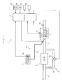
- FIG. 1 schematically shows the arrangement of the exhaust emission control device 1 according to the present embodiment, and the internal combustion engine (hereinafter referred to as "the engine") 3 to which is applied the exhaust emission control device.
- the engine 3 is (a gasoline engine or a diesel engine) of a lean-burn operation type, and is installed on a vehicle, not shown.
- the exhaust emission control device 1 is comprised of an ECU 2, a urea selective reduction catalyst 7 disposed in an exhaust passage 5 of the engine 3, a urea injection device 10 for injecting urea water into the exhaust passage 5 on the upstream side of the urea selective reduction catalyst 7, and so forth.
- the urea injection device 10 (reducing agent supply device) includes a urea injection valve 11, and a urea tank 12.
- the urea tank 12 stores urea water, and is connected to the urea injection valve 11 via a urea supply passage 13 and a urea pump (not shown).
- the urea injection valve 11 is electrically connected to the ECU 2.
- the urea injection valve 11 When the urea injection valve 11 is driven by a control signal from the ECU2, to open, the urea injection valve 11 injects urea water supplied from the urea tank 12 into the exhaust passage 5.
- urea injection control is carried out. In this case, part of urea of the urea water injected from the urea injection valve 11 is changed into ammonia by heat of exhaust gases and contact with the urea selective reduction catalyst 7.
- the urea tank 12 has a urea level sensor 20 mounted thereto.
- the urea level sensor 20 detects the level of urea water in the urea tank 12, and delivers a signal indicative of the detected level of urea water to the ECU 2.
- the ECU 2 calculates the amount Qurea of urea water remaining in the urea tank 12 (hereinafter also referred to as "the urea remaining amount Qurea") based on the signal from the urea level sensor 20.
- the urea selective reduction catalyst 7 selectively reduces nitrogen oxide (NOx) in exhaust gases under an atmosphere in which urea exists as a reducing agent.
- NOx nitrogen oxide
- ammonia that is changed from urea during injection of urea water is also consumed together with the urea by a NOx reducing action of the catalyst 7.
- a catalyst temperature sensor 21 is mounted to the urea selective reduction catalyst 7.
- the catalyst temperature sensor 21 detects the temperature Tscr of the urea selective reduction catalyst 7 (hereinafter referred to as "the catalyst temperature Tscr"), and delivers a signal indicative of the detected catalyst temperature Tscr to the ECU 2.
- the ECU 2 calculates the catalyst temperature Tscr based on the signal from the catalyst temperature sensor 21.
- an exhaust gas concentration sensor 22 is provided in the exhaust passage 5 at a location downstream of the urea selective reduction catalyst 7.
- the exhaust gas concentration sensor 22 (exhaust gas concentration-detecting means) is electrically connected to the ECU 2, and has characteristics that it is responsive to both NOx and ammonia in exhaust gases, and the value Vex of a detection signal therefrom indicative of a detected NOx/ammonia concentration in exhaust gases (hereinafter referred to as "the detection signal value Vex”) becomes larger as the concentration of NOx or that of ammonia is higher.
- the engine 3 includes an exhaust gas recirculation mechanism 8.
- the exhaust gas recirculation mechanism 8 recirculates part of exhaust gases flowing through the exhaust passage 5 into an intake passage 4, and is comprised of an EGR passage 8a connected between the intake passage 4 and the exhaust passage 5, and an EGR control valve 8b for opening and closing the EGR passage 8a.
- the EGR control valve 8b is implemented by a linear solenoid valve a valve lift of which is linearly changed between a maximum value and a minimum value thereof, and is electrically connected to the ECU 2.
- the ECU 2 changes the opening of the EGR passage 8a via the EGR control valve 8b to thereby control the amount of exhaust recirculation, i.e. the EGR amount.
- an EGR lift sensor and a differential pressure sensor are connected to the ECU 2.
- the EGR lift sensor detects the valve lift of the EGR control valve 8b, and delivers a signal indicative of the detected valve lift to the ECU 2.
- the differential pressure sensor detects the differential pressure between pressures on the upstream side and downstream side of the EGR control valve 8b, and delivers a signal indicative of the detected differential pressure to the ECU 2.
- the ECU 2 calculates an EGR ratio Regr based on the signals from the EGR lift sensor and the differential pressure sensor.
- crank angle sensor 23 is connected to the ECU 2 .
- the crank angle sensor 23 is comprised of a magnet rotor and an MRE (magnetic resistance element) pickup, and delivers a CRK signal and a TDC signal, which are both pulse signals, to the ECU 2 in accordance with rotation of a crankshaft (not shown).
- MRE magnetic resistance element
- the CRK signal is delivered whenever the crankshaft rotates through a predetermined angle (e.g. 1 ° ).
- the ECU 2 calculates the rotational speed NE of the engine 3 (hereinafter referred to as "the engine speed NE") based on the CRK signal.
- the TDC signal indicates that each piston (not shown) in an associated one of cylinders (not shown) is in a predetermined crank angle position slightly before the TDC position at the start of the intake stroke, and is delivered whenever the crankshaft rotates through a predetermined crank angle.
- the accelerator pedal opening sensor 24 detects a stepped-on amount AP of an accelerator pedal, not shown, of the vehicle (hereinafter referred to as "the accelerator pedal opening AP") and delivers a signal indicative of the detected accelerator pedal opening AP to the ECU 2.
- both the catalyst degradation warning lamp 25 and the urea remaining amount warning lamp 26 are arranged on a meter panel of the vehicle.
- the catalyst degradation warning lamp 25 is turned on.
- the amount of urea water remaining in the urea tank 12 becomes small, to indicate the fact, the urea remaining amount warning lamp 26 is turned on.
- the ECU 2 is implemented by a microcomputer comprised of a CPU, a RAM, a ROM. an I/O interface, and a drive circuit (none of which are shown).
- the ECU 2 determines an operating condition of the engine 3 in response to the signals from the aforementioned sensors 20 to 24, and carries out various control processes, such as a urea injection control process, described hereinafter.
- the ECU 2 corresponds to exhaust gas concentration-detecting means, variation value-calculating means, correlation parameter-calculating means, control input value-calculating means, supply amount-determining means, detection signal value-calculating means, NOx purification ratio parameter-calculating means, NOx purification ratio-calculating means, supply amount-correcting means, model modification value-calculating means, purification ratio-calculating means, degradation-determining means, warning means, and inhibition means.
- the exhaust emission control device 1 is comprised of an optimum value search controller 30, a feedforward controller 40, and an adder 70.
- the controllers 30 and 40 and the adder 70 are implemented by the ECU 2.
- the optimum value search controller 30 calculates the amount Gurea_fb of feedback injection (hereinafter referred to as "the FB injection amount Gurea_fb”), and a correction component Gurea_comp by a method, described hereinafter.
- the FB injection amount Gurea_fb is calculated as a value for feedback control of a controlled object to which is input a urea injection amount Gurea, and from which is output the detection signal value Vex.
- the optimum value search controller 30 corresponds to the supply amount-correcting means
- the FB injection amount Gurea_fb corresponds to the sum of the value of a control input and a variation value.
- the feedforward controller (hereinafter referred to as “the FF controller”) 40 calculates the amount Gurea_ff of feedforward injection (hereinafter referred to as “the FF injection amount Gurea_ff") by a method, described hereinafter.
- the FF injection amount Gurea_ff is calculated as a value for feedforward control of the above-described controlled object. It should be noted that in the present embodiment, the FF controller 40 corresponds to the supply amount-determining means, and the FF injection amount Gurea_ff corresponds to the amount of supplied reducing agent.
- data with a symbol (k) indicates that it is discrete data calculated or sampled at a predetermined control period ⁇ T (e.g. 5 msec).
- the symbol k indicates a control time point at which respective discrete data is calculated.
- the symbol k indicates that discrete data therewith is a value calculated in the current control timing
- a symbol k-1 indicates that discrete data therewith is a value calculated in the immediately preceding control timing.
- the symbol (k) provided for the discrete data is omitted as deemed appropriate.
- the optimum value search controller 30 calculates the FB injection amount Gurea_fb and the correction component Gurea_comp.
- the FB injection amount Gurea_fb is for feedback-controlling the urea injection amount Gurea such that the detection signal value Vex of the signal from the exhaust gas concentration sensor 22 takes a local minimum value (optimum value).
- the reason for thus calculating the FB injection amount Gurea_fb is as follows:
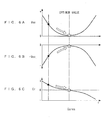
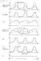
- the relationship between the urea injection amount Gurea, which is the amount of urea water injected by the urea injection valve 11, and the detection signal value Vex is as shown in FIGS. 3A to 3C since the exhaust gas concentration sensor 22 is provided on the downstream side of the urea selective reduction catalyst 7, and has the above-described characteristics.
- FIGS. 3A and 3B show an example of measurement results of the concentration of NOx and an example of measurement results of ammonia in exhaust gases on the downstream side of the urea selective reduction catalyst 7, which are obtained by changing the urea injection amount Gurea.
- FIG. 3C shows an example of measurement results of the detection signal value Vex of the signal from the exhaust gas concentration sensor 22, which are obtained by changing the urea injection amount Gurea.
- a curve indicated by a solid line shows the measurement results obtained by using the urea selective reduction catalyst 7 which is in a new condition and hence is not degraded
- a curve indicated by a broken line shows the measurement results obtained by using the urea selective reduction catalyst 7 which is degraded.
- the detection signal value Vex takes the local minimum value when the urea injection amount Gurea takes a predetermined value Gu1, and becomes larger as the urea injection amount Gurea is larger or smaller than the predetermined value Gul.
- the urea injection amount Gurea takes an optimum value which is capable of reducing both the concentration of ammonia and that of NOx in exhaust gases on the downstream side of the urea selective reduction catalyst 7 in a well-balanced manner. Further, as is apparent from the measurement results indicated by the broken line in FIG. 3C , the above relationship between the concentration of ammonia and that of NOx is satisfied even when the urea selective reduction catalyst 7 is degraded.
- the optimum value search controller 30 calculates the FB injection amount Gurea_fb with a control algorithm, described hereinafter, such that the detection signal value Vex of the signal from the exhaust gas concentration sensor 22 converges to the local minimum value.
- the optimum value search controller 30 is comprised of a reference input-calculating section 31, an inverting amplifier 32, a high-pass filter 33, a multiplier 34, a moving average filter 35, a sliding mode controller (represented by "SMC" in FIG. 4 ) 36, and an adder 70.
- the reference input-calculating section 31 calculates a reference input Ref by the following equation (2). It should be noted that in the present embodiment, the reference input-calculating section 31 corresponds to the variation value-calculating means, and the reference input Ref corresponds to a variation value.
- Ref k r ⁇ sin 2 ⁇ ⁇ Tref ⁇ n - 1 ⁇ ⁇ T
- r represents the amplitude of the reference input Ref
- Tref represents a predetermined repetition period of the reference input Ref
- n represents the number of times of control operations.
- the reference input Ref is calculated as a value that changes sinusoidally, as shown in FIG. 5 .
- the method of calculating the reference input Ref is not limited to the above-described method, but the reference input Ref may be calculated by a method in which the horizontal axis appearing in FIG. 5 is used to represent a counter value which is incremented or decremented whenever the control period ⁇ T elapses, and a table is searched according to the counter value to calculate the reference input Ref.
- the inverted value Vinv obtained by inverting the sign of the detection signal value Vex as described above is calculated for the following reason:
- the algorithm used by the optimum value search controller 30 is for searching for a local maximum value.
- the detection signal value Vex according to the present embodiment takes a local minimum value with respect to the urea injection amount Gurea, as shown in FIGS. 3C and 6A , and therefore the detection signal value Vex cannot be used as it is.
- FIG. 6B if the sign of the detection signal value Vex is inverted, the obtained value takes a local maximum value with respect to the urea injection amount Gurea, and hence in the present embodiment, the inverted value Vinv having such a characteristic is used.
- the exhaust gas concentration sensor 22 may be replaced by an exhaust gas concentration sensor a detection signal value from which varies with respect to the urea injection amount Gurea, similarly to the inverted value Vinv, that is, an exhaust gas concentration sensor a detection signal value from which takes the local maximum value with respect to the urea injection amount Gurea. In this case, it is possible to omit the inverting amplifier 32.
- the above high-pass filter 33 is for eliminating constant components and very low frequency components contained in the detection signal value Vex, and effectively extract a frequency component caused by the reference input Ref.
- the cutoff frequency of the high-pass filter 33 is set to a value capable of realizing the above-described functions.
- the method of calculating the filtered value Yf is not limited to the above-described method, but any suitable method may be used insofar as it is capable of calculating the filtered value Yf by performing a predetermined filtering process on the detection signal value Vex, thereby effectively extracting the frequency component caused by the reference input Ref from the detection signal value Vex.
- the high-pass filter 33 may be replaced by a bandpass filter such that a bandpass filtering process is performed on the detection signal value Vex, to thereby effectively extract the frequency component caused by the reference input Ref from the detection signal value Vex. In this case, it is only required to set the passband of the band pass filter to a frequency region containing the frequency component caused by the reference input Ref.
- the multiplier 34 calculates a product Z by the following equation (5):
- Z k Yf k ⁇ Ref ⁇ k - d
- d represents a dead time of the exhaust emission control device 1, i.e. a dead time it takes for exhaust gases containing urea injected from the urea injection valve 11 to reach the exhaust gas concentration sensor 22 after being reduced by the urea selective reduction catalyst 7.
- the dead time is set to a predetermined value in advance.
- the reference input Ref(k-d) the dead time d earlier is used as described above so as to multiply the current value Yf(k) of the filtered value by the reference input Ref(k-d) the dead time d earlier, which is a cause of the current value Yf(k).
- the dead time d may be calculated by a method of searching a map according to these parameters.
- the value Nref • ⁇ T corresponds to a moving average section.
- the moving average value Cr is calculated as a value obtained by calculating moving average of the product Z over sections as an integral multiple of predetermined repetition period Tref of the reference input Ref. This is to avoid generation of resonance caused by circulation of the frequency component of the reference input Ref in a closed loop formed by the relationship between the detection signal value Vex and the FB injection amount Gurea_fb in the optimum value search controller 30, as shown in FIG. 2 .
- the sliding mode controller 36 calculates a control input value Uc with a sliding mode control algorithm expressed by the following equations (7) to (10).
- ⁇ ex k Cr k + Sex ⁇ Cr ⁇ k - 1
- Uc_rch k Krch_ex ⁇ ⁇ ex k
- Uc k Uc_rch k + Uc_adp k
- ⁇ ex represents a switching function
- Sex represents a switching function-setting parameter which is set such that -1 ⁇ Sex ⁇ 0 holds.
- Uc_rch represents a reaching law input
- Krch_ex represents a predetermined reaching law gain.
- Uadp_ex represents an adaptive law input
- Kadp_ex represents a predetermined adaptive law gain.
- the control input value Uc is calculated as the sum of the reaching law input Urch_ex and the adaptive law input Uadp_ex.
- the correction component Gurea_comp is set to a value equal to the control input value Uc.
- Gurea_comp k Uc k
- the optimum value search controller 30 calculates the moving average value Cr by the moving average calculation of the product Z of the reference input Ref and the filtered value Yf over the moving average section Nref • ⁇ T, so that the moving average value Cr corresponds to a finite section correlation function between the reference input Ref and the filtered value Yf, whereby the absolute value of the moving average value Cr becomes larger as the correlation between the reference input Ref and the filtered value Yf is higher, i.e. as the correlation between the reference input Ref and the detection signal value Vex is higher, whereas as the correlation therebetween is lower, the absolute value of the moving average value Cr becomes closer to 0.
- the above-described moving average value Cr represents the correlation between the urea injection amount Gurea and the detection signal value Vex.
- the detection signal value Vex takes the local minimum value with respect to the urea injection amount Gurea
- the correlation between the detection signal value Vex and the urea injection amount Gurea becomes lower as the detection signal value Vex becomes closer to the local minimum value. More specifically, as shown in FIG.
- the detection signal value Vex becomes closer to the local minimum value
- the absolute value of the moving average value Cr monotonously increases or decreases as the urea injection amount Gurea increases or decreases. Therefore, if the urea injection amount Gurea is feedback-controlled such that the absolute value of the moving average value Cr is monotonously reduced to 0, it is possible to control the detection signal value Vex to the local minimum value.
- the optimum value search controller 30 calculates the control input value Uc with the aforementioned sliding mode control algorithm such that the moving average value Cr converges to 0, and then the adder 70 calculates the FB injection amount Gurea_fb by adding the reference input Ref to the control input value Uc. Therefore, by using the FB injection amount Gurea_fb, it is possible to feedback-control the urea injection amount Gurea such that the detection signal value Vex converges to the local minimum value.
- the sliding mode control algorithm is used as a feedback control algorithm, differently from a case where a PID control algorithm or the like is used, it is possible not only to cause the detection signal value Vex to exponentially converge to the local minimum value without causing an oscillating behavior or an unstable behavior even when the detection signal value Vex has become close to the local minimum value but also to maintain the detection signal value Vex at the local minimum value or in its vicinity after conversion.
- control algorithm for calculating the control input value Uc is not limited to the aforementioned sliding mode control algorithm but any suitable algorithm may be used insofar as it is an algorithm to which is applied a predetermined response-specifying control algorithm.
- the control input value Uc may be calculated with a back-stepping control algorithm.
- a feedback control algorithm such as the PID control algorithm or an optimum control algorithm, may be used as a control algorithm for calculating the control input value Uc.
- the adaptive law input Uadp_ex an integration element (the adaptive law input Uadp_ex) is contained in the control algorithm as in the optimum value search controller 30, but under a condition where some degree of the steady-state deviation is allowed, the adaptive law input Uadp may be calculated by the following equation (13) in place of the aforementioned equation (9).
- Uc_adp k ⁇ a ⁇ Uc_adp ⁇ k - 1 + Kadp_ex ⁇ ⁇ ex k
- ⁇ a represents a forgetting coefficient which is set to a value (e.g. 0.99) such that 0 « ⁇ a ⁇ 1 holds.
- the FF controller 40 is for calculating an FF injection amount Gurea_ff for feedforward-controlling the urea injection amount Gurea, and as shown in FIG. 7 , it includes an NOx emission amount-calculating section 41, a reduced NOx amount-calculating section 42, an FF injection amount-calculating section 43, and a model modifier 50.
- the NOx emission amount-calculating section 41 is for calculating the amount of NOx estimated to be emitted, i.e. exhausted from the engine 3, as an NOx emission amount Gnox_eng_hat by a method, described hereinafter. It should be noted that in the present embodiment, the NOx emission amount-calculating section 41 corresponds to the NOx purification ratio parameter-calculating means.
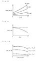
- a map for use in calculating a map value Gnox_eng_bs of the NOx emission amount is selected from a plurality of maps according to an operation mode value STS_MOD.
- the operation mode value STS_MOD represents the operation mode of the engine 3, and is set according to various operating parameters (the engine speed NE, the accelerator pedal opening AP, the vehicle speed, etc.).
- NE1 to NE3 represent predetermined values of the engine speed NE, which are set such that NE1 ⁇ NE2 ⁇ NE3 holds.
- the map value Gnox_eng_bs is set to a larger value. This is because as the load on the engine 3 is higher, the combustion temperature of a mixture becomes higher to increase the NOx emission amount, and as the engine speed NE is higher, the amount of NOx emitted, i.e. exhausted per unit time increases.
- the demanded torque Pmcmd is calculated by searching a map, not shown, according to the engine speed NE and the accelerator pedal opening AP.
- the map value Gnox_eng_bs of the NOx emission amount is calculated by searching the above-described selected map according to the engine speed NE and the demanded torque Pmcmd.
- an EGR-dependent correction coefficient Knox_eng is calculated by searching a table shown in FIG. 9 according to the EGR ratio Regr.
- the NOx emission amount-calculating section 41 finally calculates the NOx emission amount Gnox_eng_hat by the following equation (14):
- Gnox_eng_hat k Knox_eng k ⁇ Gnox_eng_bs k
- the reduced NOx amount-calculating section 42 is for calculating the amount of NOx estimated to be reduced by the urea selective reduction catalyst 7, as a reduced NOx amount Gnox_red_hat by a method, described hereinafter. It should be noted that in the present embodiment, the reduced NOx amount-calculating section 42 corresponds to the NOx purification ratio-calculating means and the purification ratio-calculating means.
- a map value Ita_scr_bs of an estimated NOx purification ratio is calculated by searching a map shown in FIG. 10 according to the above-mentioned NOx emission amount Gnox_eng_hat and catalyst temperature Tscr.
- Tscr1 to Tscr3 represent predetermined values of the catalyst temperature Tscr, which are set such that Tscr1 ⁇ Tscr2 ⁇ Tscr3 holds.
- the map value Ita_scr_bs is set such that it becomes smaller, as the NOx emission amount Gnox_eng_hat is larger. This is because as the NOx emission amount Gnox_eng_hat is larger, the probability of NOx being brought into contact with the urea selective reduction catalyst 7 becomes lower.
- a predetermined temperature range e.g. 300 to 500°C.
- the FIG. 10 map is set based on average characteristics of the urea selective reduction catalyst 7 in a new condition, and corresponds to a correlation model in the present embodiment.
- Ita_scr_hat k Kff ⁇ k - 1 ⁇ Ita_scr_bs k
- Kff represents a model modification coefficient, which is calculated as a positive value by a model modifier 50, as described hereinafter.
- the estimated NOx purification ratio Ita_scr_hat is calculated by modifying the map value Ita_scr_bs with the model modification coefficient Kff.
- the NOx emission amount Gnox_eng_hat and the catalyst temperature Tscr correspond to a NOx purification ratio parameter
- the map value Ita_scr_bs corresponds to the NOx purification ratio assumed when the selecting reduction catalyst is in a condition degraded to a predetermined degree
- the estimated NOx purification ratio Ita_scr_hat corresponds to the NOx purification ratio.
- Knox_urea represents a conversion coefficient for converting the reduced NOx amount Gnox_red_hat to the urea injection amount, and is set to a predetermined value in advance according to a ratio between urea and water in urea water.
- the model modifier 50 is for calculating the model modification coefficient Kff.
- the model modification coefficient Kff is for modifying (or correcting) the map value Ita_scr_bs, i.e. for modifying the FIG. 10 map, as a correlation model, which is set based on the average characteristics of the new urea selective reduction catalyst 7.
- the model modifier 50 corresponds to the model modification value-calculating means
- the model modification coefficient Kff corresponds to a model modification value.
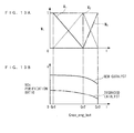
- FIG. 11A shows the relationship between the NOx emission amount, the catalyst temperature Tscr and the NOx purification ratio, obtained by using the urea selective reduction catalyst 7 when the urea selective reduction catalyst 7 is in a new and undegraded condition.
- FIG. 11B shows the relationship therebetween obtained by using the urea selective reduction catalyst 7 when the urea selective reduction catalyst 7 is in a degraded condition.
- the model modifier 50 is comprised of three nonlinear weight function-calculating sections 51 to 53, three sliding mode controllers (represented by "SMCs" in FIG. 12 ) 54 to 56, three multipliers 57 to 59, and two adders 60 and 61.
- SMCs sliding mode controllers
- Gn1 to Gn3 represent predetermined values of the NOx emission amount Gnox_eng_hat, which are set such that 0 ⁇ Gn1 ⁇ Gn2 ⁇ Gn3 holds.
- the subscript i of the nonlinear weight function W i represents each of values associated with three regions, described hereinafter, of the NOx emission amount Gnox_eng_hat. This relationship also applies to various values, described hereinafter. More specifically, a nonlinear weight function W 1 is associated with a first region defined as 0 ⁇ Gnox_eng_hat ⁇ Gn2; a nonlinear weight function W 2 is associated with a second region defined as Gn1 ⁇ Gnox_eng_hat ⁇ Gn3; and a nonlinear weight function W 3 is associated with a third region defined as Gn2 ⁇ Gnox_eng_hat.
- each of the three nonlinear weight functions W i is set to a positive value not larger than 1 in the above-described regions associated therewith, and set to 0 in the other regions.
- the two adjacent nonlinear weight functions W 1 and W 2 intersect with each other between the predetermined value Gn1 and the predetermined value Gn2, and the NOx emission amount Gnox_eng_hat at the intersection of the two W1 and W2 forms a gradient change point across which the gradient of the NOx purification ratio changes, as shown in FIG. 13B .
- the two adjacent nonlinear weight functions W 2 and W 3 intersect with each other between the predetermined value Gn2 and the predetermined value Gn3, and the NOx emission amount Gnox_eng_hat at the intersection of the two W 2 and W 3 forms a gradient change point across which the gradient of the NOx purification ratio changes.
- the NOx purification ratio of the urea selective reduction catalyst 7 has the above-described gradient change point, and at the same time changes while maintaining the position of the gradient change point. This makes it necessary to calculate the model modification coefficient Kff such that it has different gradients between regions associated with the gradient change points.
- an intersection of two adjacent nonlinear weight functions W i is set such that it is associated with a gradient change point of the NOx purification ratio.
- two nonlinear weight functions W j and W j+1 may be set such that they intersect with each other in a region containing gradient change points of the respective NOx purification ratio of the urea selective reduction catalyst 7 in a new condition and the urea selective reduction catalyst 7 in a degraded condition.
- a large number of nonlinear weight functions W it is only required to increase the number of nonlinear weight functions W associated with a region containing gradient change points to densely arrange the nonlinear weight functions in the region.
- the modification coefficients ⁇ i are for modifying the three nonlinear weight functions W i , and as described hereinafter, they are calculated with an algorithm [equations (18) to (25)] to which is applied an adaptive sliding mode control algorithm.
- the modeling error Eff is calculated by the above-mentioned equation (18) for the following reason:
- the model modification coefficient Kff by which is multiplied the map value Ita_scr_bs, is for calculating the estimated NOx purification ratio Ita scr hat, and hence is expressed in units of NOx purification ratio (%).
- the three distributed errors Ew i are calculated by multiplying the modeling error Eff by the three nonlinear weight functions W i , so that they are calculated as values obtained by distributing the modeling error Eff to the aforementioned first to third three regions of the NOx emission amount Gnox_eng_hat.
- ⁇ w i represents a switching function
- S represents a switching function-setting parameter set to a value which satisfies the relationship of -1 ⁇ S ⁇ 0.
- ⁇ rch i represents a reaching law input
- Krch i represents a predetermined reaching law gain.
- ⁇ adp i represents an adaptive law input
- Kadp i represents a predetermined adaptive law gain.
- ⁇ represents a forgetting coefficient
- the value thereof is set to 1 or a predetermined value ⁇ lmt, according to the results of comparison between the immediately preceding value ⁇ i (k-1) of the modification coefficient and predetermined upper and lower limit values ⁇ H and ⁇ L.
- the upper limit value ⁇ H is set to a predetermined positive value
- the lower limit value ⁇ L is set to a predetermined negative value
- the predetermined value ⁇ lmt is set to a value which satisfies the relationship of 0 ⁇ ⁇ lmt ⁇ 1.
- the modification coefficient ⁇ i is calculated as the sum of a reaching law input ⁇ rch i and an adaptive law input ⁇ adp i .
- the forgetting coefficient ⁇ is used in the algorithm for calculating the modification coefficient ⁇ i for the following reason:
- a cause e.g. a disturbance
- the modification coefficient ⁇ i is erroneously adapted and temporarily made improper, which degrades transient controllability.
- the forgetting coefficient ⁇ is always set to a value within the range of 0 ⁇ ⁇ ⁇ 1, when the region of the modification coefficient ⁇ i is changed to make Ew i equal to 0 or when the above-described cause is eliminated to thereby make Ew i approximately equal to 0, the modification coefficient ⁇ i comes to converge to a value close to 0 due to a forgetting effect provided by the forgetting coefficient ⁇ , so that when a large modeling error Eff occurs again in such a state, it takes time to eliminate the modeling error Eff.
- the forgetting coefficient ⁇ when ⁇ L ⁇ ⁇ i (k-1) ⁇ ⁇ H holds, the forgetting coefficient is set to 1 so as to cancel the forgetting effect provided by the forgetting coefficient ⁇ . It should be noted that when the forgetting effect by the forgetting coefficient ⁇ is always unnecessary, the forgetting coefficient ⁇ may be set to 1 in the equation (22) irrespective of the magnitude of the immediately preceding value ⁇ i (k-1) of the modification coefficient.
- the three modification coefficients ⁇ i are calculated with the adaptive sliding mode control algorithm such that the correction component Gurea_comp for the three regions of the NOx emission amount Gnox_eng_hat with which the three nonlinear weight functions W i are associated, respectively, becomes equal to 0. Since the correction component Gurea_comp is equal to the control input value Uc, the modification coefficients ⁇ i are calculated such that the control input value Uc calculated by the optimum value search controller 30 becomes equal to 0 (i.e. such that the absolute value of the control input value Uc decreases). In other words, the modification coefficients ⁇ i are calculated such that the necessity of feedback-controlling the detection signal value Vex to the local minimum value by the control input value Uc decreases.
- FIGS. 14A to 14D show examples of calculations of values by the model modifier 50.
- the three products ⁇ i W i are calculated as values which change in a manner different from each other, while the model modification coefficient Kff is calculated as a value which nonlinearly changes with respect to the NOx emission amount Gnox_eng_hat.
- the map value Ita_scr_bs of the estimated NOx purification ratio can be nonlinearly modified by the model modification coefficient Kff.
- the model modifier 50 calculates the modification coefficients ⁇ i such that the necessity of feedback-controlling the detection signal value Vex to the local minimum value by the control input value Uc is reduced, calculates the model modification coefficient Kff while modifying the nonlinear weight functions W i by the modification coefficients ⁇ i calculated as above, and further calculates the estimated NOx purification ratio Ita_scr_hat by modifying the map value Ita_scr_bs using the calculated model modification coefficient Kff.
- This control process is for calculating the urea injection amount Gurea by the aforementioned method, and is carried out at the predetermined control period ⁇ T, mentioned hereinabove.
- a urea failure flag F_UREANG is set to 1 when it is determined in a determination process, not shown, that the urea injection device 10 is faulty, and otherwise set to 0.
- step 1 If the answer to the question of the step 1 is affirmative (YES), i.e. if the urea injection device 10 is faulty, it is determined that injection of urea by the urea injection device 10 should be stopped, and the process proceeds to a step 15, wherein the urea injection amount Gurea is set to 0, followed by terminating the present process.
- step 1 if the answer to the question of the step 1 is negative (NO), i.e. if the urea injection device 10 is normal, the process proceeds to a step 2, wherein it is determined whether or not a catalyst degradation flag F_SCRNG is equal to 1. If the answer to this question is negative (NO), i.e. if the urea selective reduction catalyst 7 is not degraded, the process proceeds to a step 3, wherein it is determined whether or not a urea remaining amount Qurea is smaller than a predetermined value Qref.
- a warning sound may be generated for notifying a driver of the urea remaining amount Qurea being small in addition to lighting of the urea remaining amount warning lamp 26.
- step 4 if the answer to the question of the step 3 is negative (NO), i.e. if the urea remaining amount Qurea is large, the process proceeds to a step 4, wherein it is determined whether or not a catalyst warmup timer value Tmast is larger than a predetermined value Tmlmt.
- the catalyst warmup timer value Tmast is for counting a time period it takes to warm up the catalyst after the start of the engine 3.
- step 4 If the answer to the question of the step 4 is negative (NO), it is determined that injection of urea should be stopped since the oxidation catalyst is not yet activated, and the urea injection amount Gurea is set to 0 in the aforementioned step 15, followed by terminating the present process.
- step 4 determines whether or not the oxidation catalyst is active, and the process proceeds to a step 5, wherein it is determined whether or not the catalyst temperature Tscr is higher than a predetermined value Tscr_act. If the answer to this question is negative (NO), it is determined that injection of urea should be stopped since the oxidation catalyst is not yet activated, and the urea injection amount Gurea is set to 0 in the aforementioned step 15, followed by terminating the present process.
- step 5 determines that the urea selective reduction catalyst 7 is active, and the process proceeds to a step 6, wherein the FB injection amount Gurea_fb is calculated by the aforementioned equations (2) to (11), and the correction component Gurea_comp is calculated by the aforementioned equation (12).
- the process proceeds to a step 7, wherein the FF injection amount Gurea_ff is calculated by the aforementioned equations (14) to (17).
- the urea injection amount Gurea is set to the sum (Gurea_fb + Gurea_ff) of the FB injection amount and the FF injection amount.
- ⁇ ref represents a reference value for determining the degradation of the urea selective reduction catalyst 7, and is set to a predetermined negative value (e.g. -0.8).
- Kref as well represents a reference value (predetermined value) for determining the degradation of the urea selective reduction catalyst 7, and is set to a predetermined positive value (e.g. 0.2) smaller than 1.
- step 10 If the answer to the question of the step 10 is negative (NO), i.e. if none of the above-described four conditions (f1) to (f4) are satisfied, it is determined that the urea selective reduction catalyst 7 is not degraded, and the process proceeds to a step 11, wherein to indicate that the urea selective reduction catalyst 7 is not degraded, the catalyst degradation flag F_SCRNG is set to 0, followed by terminating the present process.
- step 10 determines whether the urea selective reduction catalyst 7 is degraded, and the process proceeds to a step 12, wherein to indicate the degradation of the urea selective reduction catalyst 7, the catalyst degradation flag F_SCRNG is set to 1, followed by terminating the present process.
- the process proceeds to a step 13, wherein to indicate the degradation of the urea selective reduction catalyst 7, the urea remaining amount warning lamp 26 is turned on. Then, to stop injection of urea, the urea injection amount Gurea is set to 0 in the above-described step 15, followed by terminating the present process. It should be noted that in the step 13, a warning sound may be generated for notifying the driver of the degradation of the urea selective reduction catalyst 7 in addition to lighting of the catalyst degradation warning lamp 25.
- FIGS. 16 and 17 show examples of the control results by the exhaust emission control device 1 according to the present embodiment. Particularly, FIG. 16 shows examples of control results obtained when there is no modeling error in the FIG. 10 map, and FIG. 17 shows examples of control results obtained when there is a modeling error in the FIG. 10 map.
- FIG. 18 and FIG. 19 show examples of the control results obtained when there is no modeling error and when there is a modeling error, respectively, by omitting only the model modifier 50 of the exhaust emission control device 1, i.e. by setting Kff to 1.
- FIG. 20 and FIG. 21 show examples of the control results obtained when there is no modeling error and when there is a modeling error, respectively, in the case of both the optimum value search controller 30 and the model modifier 50 being omitted, i.e. Gurea_fb being set to 0 and Kff being set to 1.
- Gnox_scr represents a post-catalyst NOx amount which indicates the amount of NOx in exhaust gases on the downstream side of the urea selective reduction catalyst 7
- Slip_NH3 represents a slip value which indicates the amount of ammonia in exhaust gases on the downstream side of the urea selective reduction catalyst 7.
- Gurea_best represents the optimum value of the urea injection amount Gurea, which is capable of causing the detection signal value Vex of the signal from the exhaust gas concentration sensor 22 to converge to the local minimum value.
- the urea injection amount Gurea takes a value approximately equal to the optimum value Gurea_best, and the slip value Slip_NH3 is held at a very small value, thereby ensuring excellent reduction of exhaust emissions.
- the urea injection amount Gurea temporally deviates from (i.e.
- the urea injection amount Gurea temporally deviates from the optimum value Gurea_best between time points t1 and t2, and the slip value Slip_NH3 temporally increases at a first increase in the NOx emission amount Gnox_eng_hat that periodically increases.
- the urea injection amount Gurea takes a value approximately equal to the optimum value Gurea_best and the slip value Slip_NH3 is held at a very small value, thereby ensuring an excellent reduction of exhaust emissions.
- the modification coefficients ⁇ i i.e. the model modification coefficient Kff is calculated so as to compensate for the modeling error in the FIG. 10 map, whereby the estimated NOx purification ratio Ita_scr_hat becomes closer to the actual value Ita_scr_act.
- the optimum value search controller 30 calculates the moving average value Cr, which represents the correlation between the detection signal value Vex of the signal from the exhaust gas concentration sensor 22 and the reference input Ref, based on the detection signal value Vex and the reference input Ref, calculates the control input value Uc such that the moving average value Cr converges to 0, and calculates the urea injection amount Gurea such that it contains the control input Uc.
- the moving average value Cr becomes closer to 0, and hence by the control input value Uc, it is possible to cause the detection signal value Vex to converge to the local minimum value.
- the urea injection amount Gurea takes the optimum value which is capable of reducing both the concentration of ammonia and that of NOx in exhaust gases on the downstream side of the urea selective reduction catalyst 7 in a well-balanced manner. Therefore, by using the control input value Uc, it is possible to control the urea injection amount Gurea to the optimum value described above, thereby making it possible to reduce both the concentration of ammonia and that of NOx in exhaust gases on the downstream side of the urea selective reduction catalyst 7 in a well-balanced manner. As a result, even when the NOx purification ratio of the urea selective reduction catalyst 7 is changed by various causes, it is possible to maintain high NOx purification ratio and very low reduced exhaust emissions.
- control input value Uc is calculated with the sliding mode control algorithm [the equations (7) to (10)] such that the moving average value Cr converges to 0, and therefore when the detection signal value Vex has become close to the local minimum value or its vicinity, i.e. even when the urea injection amount Gurea has become close to the optimum value or its vicinity, it is possible not only to cause the urea injection amount Gurea to exponentially converge to the optimum value without causing an oscillating behavior or unstable behavior but also to maintain the urea injection amount Gurea at the optimum value or in its vicinity after conversion. This makes it possible not only to cause the detection signal value Vex to exponentially converge to the local minimum value but also to maintain the detection signal value Vex at the local minimum value or in its vicinity after conversion. As a result, even when the NOx purification ratio of the urea selective reduction catalyst 7 is changed by various causes, it is possible to further enhance the NOx purification ratio and reduce exhaust emissions.
- the moving average value Cr is calculated by integrating the product Z over the moving average section Nref • ⁇ T, which is a section of an integral multiple of predetermined repetition period Tref of the reference input Ref, so that it is possible to prevent the frequency of the reference input Ref from being mixed with the control input value Uc, thereby making it possible to avoid circulation of the frequency component of the reference input Ref in the closed loop including the optimum value search controller 30. This makes it possible to ensure stability of the control system.
- the FF controller 40 calculates the map value Ita_scr_bs of the estimated NOx purification ratio by searching the FIG. 10 map according to the urea catalyst temperature Tscr and the NOx emission amount Gnox_eng_hat, calculates the estimated NOx purification ratio Ita_scr_hat by modifying the map value Ita_scr_bs by the model modification coefficient Kff, and calculates the FF injection amount Gurea_ff based on the estimated NOx purification ratio Ita_scr_hat. Then, the FF controller 40 calculates the urea injection amount Gurea by adding the FB injection amount Gurea_fb to the FF injection amount Gurea_ff. That is, the urea injection amount Gurea is calculated by correcting the FF injection amount Gurea_ff by the FB injection amount Gurea_fb.
- the FF controller 40 calculates the FF injection amount Gurea_ff with the feedforward control algorithm, as described hereinbefore, and hence it is possible to properly supply a reducing agent to the urea selective reduction catalyst 7 without causing the above-described response delay.
- the model modifier 50 calculates the modification coefficients ⁇ i such that the correction component Gurea_comp, i.e. the control input value Uc converges to 0, and calculates the model modification coefficient Kff using the thus calculated modification coefficients ⁇ i .
- the reduced NOx amount-calculating section 42 calculates the estimated NOx purification ratio Ita_scr_hat by modifying the map value Ita_scr_bs of the estimated NOx purification ratio by the model modification coefficient Kff, so that even when the actual NOx purification ratio of the urea selective reduction catalyst 7 is changed by various causes, it is possible to properly calculate the estimated NOx purification ratio Ita_scr_hat while coping the change in the actual NOx purification ratio. For the above reason, it is possible to maintain a high NOx purification ratio and very low exhaust emissions.
- the model modifier 50 calculates the model modification coefficient Kff by multiplying the modification coefficients ⁇ i by the nonlinear weight functions W i and adding the multiplication sum Kff', which is the total sum of the products ⁇ i W i obtained by the above multiplication, to 1. Therefore, when the actual relationship between the NOx emission amount Gnox_eng_hat and the NOx purification ratio suffers from a local error or a change due to aging in any of the above-described three regions, or even when there is variation in the above actual relationship between the three regions, the relationship between the NOx emission amount Gnox_eng_hat and the estimated NOx purification ratio Ita_scr_hat can be caused to properly match the actual relationship.
- each of the three nonlinear weight functions W i is set to a positive value not larger than 1 in the above-described region associated therewith, and to 0 in the other regions.
- the correction component Gurea_comp for use in calculating the modeling error is the control input value Uc which is calculated such that the frequency of the reference input Ref is prevented from being mixed therewith, so that it is possible to avoid circulation of the frequency component of the reference input Ref in the closed loop including the FF controller 40. This makes it possible to ensure stability of the control system.
- the urea injection control process shown in FIG. 15 when the model modification coefficient Kff becomes larger than the predetermined value Kref, it is determined that the urea selective reduction catalyst 7 is degraded, and the catalyst degradation warning lamp 25 is turned on, whereby it is possible to properly notify the driver of the degradation of the urea selective reduction catalyst 7. This makes it possible to prevent operation of the engine 3 from being continued in spite of degradation of the urea selective reduction catalyst 7, thereby making it possible to prevent exhaust emissions from being increased.
- the urea injection amount Gurea is calculated such that it becomes equal to 0, and injection of urea is stopped. This stops the reducing agent from being supplied to the urea selective reduction catalyst 7 in spite of degradation of the catalyst 7, whereby it is possible to prevent the reducing agent from flowing out downstream of the urea selective reduction catalyst 7, which makes it possible to avoid an increase in exhaust emissions.
- the layout of the exhaust system for the engine 3, to which is applied the exhaust emission control device 1 according to the invention is not limited to this, but the exhaust system may be configured such that various catalysts and filters are arranged in the exhaust passage 5.
- a three-way catalyst may be disposed at a location upstream or downstream of the urea selective reduction catalyst 7.
- an oxidation-reduction catalyst and a DPF Diesel Particulate Filter
- a DPF Diesel Particulate Filter
- the exhaust gas concentration sensor 22 is used as the exhaust gas concentration-detecting means
- the exhaust gas concentration-detecting means of the present invention is not limited to this, but any suitable exhaust gas concentration-detecting means may be used insofar as it delivers detection signals indicative of the detected concentration of NOx and that of a reducing agent in exhaust gases, and has a characteristic that the direction of a change in a detection signal value responsive to an increase/decrease of the NOx concentration is the same as the direction of a change in the value of the detection signal responsive to an increase/decrease of the concentration of the reducing agent.
- an exhaust gas concentration sensor that detects the concentration of urea and that of NOx in exhaust gases, and delivers a signal indicative of the detected concentration of urea and that of NOx may be used as the exhaust gas concentration-detecting means.
- the exhaust gas concentration-detecting means may be constructed as follows: A NOx concentration sensor for detecting only the concentration of NOx in exhaust gases, and an ammonia concentration sensor for detecting only the concentration of ammonia in exhaust gases are arranged in the exhaust passage at locations downstream of the urea selective reduction catalyst, and these sensors are electrically connected to the ECU 2.
- a NOx concentration sensor a NOx concentration sensor is employed which has a characteristic that when the concentration of NOx in exhaust gases changes as shown in FIG. 22A , a detection signal value Vnox of a signal from the NOx concentration sensor changes as shown in FIG.
- an ammonia concentration sensor which has a characteristic that when the concentration of ammonia in exhaust gases changes as shown in FIG. 22B , a detection signal value Vnh3 of a signal from the ammonia concentration sensor changes as shown in FIG. 22D .
- Kfsn represents a predetermined composite coefficient, and as shown in FIG. 22E , is set to a value which is capable of making the curve of the detection signal value Vex as symmetrical as possible with respect to the optimum value of the urea injection amount Gurea as the center.
- the detection signal value Vex calculated by the method as described above is used, it is possible to obtain the same advantageous effects as provided by the above-described embodiment.
- the NOx concentration sensor corresponds to the NOx concentration-detecting means
- the ammonia concentration sensor corresponds to the reducing agent concentration-detecting means
- the ECU 2 corresponds to the detection signal value-calculating means.
- the optimum value search controller 30 may be replaced by an optimum value search controller 80 shown in FIG. 23 .
- the optimum value search controller 80 is for calculating the FB injection amount Gurea_fb and the correction component Gurea_comp by a method, described hereinafter.
- the optimum value search controller 80 is comprised of a reference input-calculating section 81, an inverting amplifier 82, a high-pass filter 83, a multiplier 84, an integrator 85, an amplifier 86, an adder 87, and a moving average filter 88.
- the four elements 81 to 84 of the optimum value search controller 80 calculate the reference input Ref, the inverted value Vinv, the filtered value Yf, and the product Z by the following equations (29) to (32):
- Yf k 0.5 ⁇ Vinv k - 0.5 ⁇ Vinv ⁇ k - 1
- Z k Yf k ⁇ Ref ⁇ k - d
- the optimum value search controller 80 configured as above is used, similarly to the case where the optimum value search controller 30 is used, it is possible to obtain the above-described advantageous effects.
- the correction component Gurea_comp is calculated as a value obtained by performing the moving average filtering process on the FB injection amount Gurea_fb, it is possible to prevent the frequency component of the reference input Ref from being mixed with the model modification coefficient Kff. This makes it possible to prevent the frequency component of the reference input Ref from circulating in a closed loop of a system to which is input the FF injection amount Gurea_ff, and from which is output the detection signal value Vex. This makes it possible to avoid generation of resonance caused by the circulation of the frequency component of the reference input Ref.
- the moving average filtering process may be performed on the control input value Uc' to thereby calculate the correcting component Gurea_comp, as shown in the following equation (37) which is used in place of the above equation (36).
- the frequency component of the reference input Ref can be prevented from circulating in the closed loop of the system to which is input the FF injection amount Gurea_ff, and from which is output the detection signal value Vex, thereby making it possible to avoid generation of resonance caused by the circulation of the frequency component of the reference input Ref.
- the optimum value search controller 80 corresponds to the supply amount-determining means, the reference input-calculating section 81 to the variation value-calculating means, the integrator 85 to the correlation parameter-calculating means, the amplifier 86 to the control input value-calculating means, and the integral value Cr' to the correlation parameter.
- the optimum value search controller 30 may be replaced by an ESC controller ( FIG. 12 ), which has already been proposed by the present assignee in Japanese Laid-Open Patent Publication (Kokai) No. 2006-105031 , for calculating the FB injection amount Gurea_fb and the correction component Gurea_comp with an algorithm for the ESC controller.
- the optimum value search controller 80 similarly to the optimum value search controller 80, it is possible to prevent the frequency component of the reference input Ref from circulating in the closed loop, thereby making it possible to avoid generation of resonance caused by the circulation of the frequency component of the reference input Ref.
- the number of the nonlinear weight functions W i is set to 3, by way of example, this is not limitative, but the number thereof may be set to 1, 2 or an integer not smaller than 4. Particularly when the NOx purification ratio of the urea selective reduction catalyst 7 uniformly changes with respect to the NOx emission amount Gnox_eng_hat, the number of the nonlinear weight functions W i can be set to 1. In this case, it is possible to reduce the load on the EPU 2.
- the variation value according to the present invention is not limited to this, but any suitable variation value may be used insofar as it has an amplitude that changes periodically at a predetermined repetition period.
- a value that changes in the form of a periodic function such as a value that changes cosinusoidally or a value that changes in a triangular wave form, may be used.
- urea is used as the reducing agent
- the reducing agent according to the present invention is not limited to this, but any suitable reducing agent may be used insofar as it accelerates the reducing action of NOx in a selective reduction catalyst.
- ammonia, deuterium (H 2 ), or ethanol may be used as a reducing agent.
- a selective reduction catalyst may be used which is capable of reducing NOx effectively according to the kind of a used reducing agent.
- the correlation model according to the present invention is not limited to this, but any correlation model may be used insofar as it defines the relationship between the NOx purification ratio parameter and the NOx purification ratio of the selective reduction catalyst at a predetermined degree of degradation.
- a mathematical expression may be used as a correlation model.
- a correlation model which uses the NOx purification ratio of the selective reduction catalyst that is in a new and not degraded condition i.e.
- the NOx emission amount Gnox_eng_hat and the catalyst temperature Tscr are used as NOx purification ratio parameters
- the NOx purification ratio parameters of the present invention are not limited to these, but any suitable NOx purification ratio parameters may be used insofar as they have correlation between the same and the NOx purification ratio of the selective reduction catalyst.
- the positive model modification coefficient Kff is used as the model modification value
- a negative model modification coefficient may be used in place of the positive model modification coefficient Kff.
- a value obtained by inverting the sign of the model modification coefficient Kff may be used as the model modification value.
- it is only required that it is determined in the step 10 whether or not the absolute value of the model modification coefficient Kff is not larger than the predetermined reference value Kref, and the estimated NOx purification ratio Ita_scr_hat is calculated by an equation in which Kff(k-1) on the right side of the equation (15) is replaced by [-Kff'(k-1)].
Landscapes
- Engineering & Computer Science (AREA)
- Chemical & Material Sciences (AREA)
- Chemical Kinetics & Catalysis (AREA)
- Combustion & Propulsion (AREA)
- Mechanical Engineering (AREA)
- General Engineering & Computer Science (AREA)
- Health & Medical Sciences (AREA)
- Toxicology (AREA)
- Exhaust Gas After Treatment (AREA)
- Exhaust Gas Treatment By Means Of Catalyst (AREA)
- Combined Controls Of Internal Combustion Engines (AREA)
Applications Claiming Priority (2)
| Application Number | Priority Date | Filing Date | Title |
|---|---|---|---|
| JP2007153278A JP4767218B2 (ja) | 2007-06-08 | 2007-06-08 | 内燃機関の排ガス浄化装置 |
| EP08009281A EP2000641B1 (fr) | 2007-06-08 | 2008-05-20 | Dispositif de contrôle d'émissions d'échappement d'un moteur à combustion interne |
Related Parent Applications (1)
| Application Number | Title | Priority Date | Filing Date |
|---|---|---|---|
| EP08009281.0 Division | 2008-05-20 |
Publications (2)
| Publication Number | Publication Date |
|---|---|
| EP2320043A1 true EP2320043A1 (fr) | 2011-05-11 |
| EP2320043B1 EP2320043B1 (fr) | 2012-12-05 |
Family
ID=39708895
Family Applications (2)
| Application Number | Title | Priority Date | Filing Date |
|---|---|---|---|
| EP08009281A Expired - Fee Related EP2000641B1 (fr) | 2007-06-08 | 2008-05-20 | Dispositif de contrôle d'émissions d'échappement d'un moteur à combustion interne |
| EP10197409A Expired - Fee Related EP2320043B1 (fr) | 2007-06-08 | 2008-05-20 | Dispositif de contrôle d'émissions d'échappement d'un moteur à combustion interne |
Family Applications Before (1)
| Application Number | Title | Priority Date | Filing Date |
|---|---|---|---|
| EP08009281A Expired - Fee Related EP2000641B1 (fr) | 2007-06-08 | 2008-05-20 | Dispositif de contrôle d'émissions d'échappement d'un moteur à combustion interne |
Country Status (4)
| Country | Link |
|---|---|
| US (1) | US7997070B2 (fr) |
| EP (2) | EP2000641B1 (fr) |
| JP (1) | JP4767218B2 (fr) |
| DE (1) | DE602008005951D1 (fr) |
Cited By (2)
| Publication number | Priority date | Publication date | Assignee | Title |
|---|---|---|---|---|
| US8978367B2 (en) | 2012-05-31 | 2015-03-17 | Honda Motor Co., Ltd. | Exhaust gas purifying system of internal combustion engine |
| CN109072749A (zh) * | 2016-05-13 | 2018-12-21 | 瓦锡兰芬兰有限公司 | 用于为内燃发动机的减排系统控制还原剂喷射的方法 |
Families Citing this family (53)
| Publication number | Priority date | Publication date | Assignee | Title |
|---|---|---|---|---|
| JP4432917B2 (ja) * | 2006-03-06 | 2010-03-17 | トヨタ自動車株式会社 | 内燃機関の排気浄化装置 |
| FR2926592B1 (fr) * | 2008-01-18 | 2012-07-13 | Peugeot Citroen Automobiles Sa | Procede d'injection d'agent reducteur dans une ligne d'echappement |
| DE102008001213A1 (de) * | 2008-04-16 | 2009-10-22 | Robert Bosch Gmbh | Verfahren und Vorrichtung zur Diagnose der Dynamik eines Abgassensors |
| US8161730B2 (en) * | 2008-04-30 | 2012-04-24 | Cummins Ip, Inc. | Apparatus, system, and method for reducing NOx emissions on an SCR catalyst |
| US8141340B2 (en) * | 2008-04-30 | 2012-03-27 | Cummins Ip, Inc | Apparatus, system, and method for determining the degradation of an SCR catalyst |
| US8505278B2 (en) * | 2009-04-30 | 2013-08-13 | Cummins Ip, Inc. | Engine system properties controller |
| US8201394B2 (en) * | 2008-04-30 | 2012-06-19 | Cummins Ip, Inc. | Apparatus, system, and method for NOx signal correction in feedback controls of an SCR system |
| US8256208B2 (en) * | 2008-04-30 | 2012-09-04 | Cummins Ip, Inc. | Apparatus, system, and method for reducing NOx emissions on an SCR catalyst |
| US8281572B2 (en) * | 2008-04-30 | 2012-10-09 | Cummins Ip, Inc. | Apparatus, system, and method for reducing NOx emissions from an engine system |
| DE102008047860B3 (de) * | 2008-09-18 | 2009-12-24 | Continental Automotive Gmbh | Verfahren zur Dichtheitsprüfung eines Reagenzmittelinjektors |
| US8356471B2 (en) * | 2008-12-05 | 2013-01-22 | Cummins Ip, Inc. | Apparatus, system, and method for controlling reductant dosing in an SCR catalyst system |
| WO2010065963A2 (fr) * | 2008-12-05 | 2010-06-10 | Cummins Ip, Inc. | Appareil, système et procédé d'estimation de l'efficacité de la conversion du nox d'un catalyseur de réduction catalytique sélective |
| US9657630B2 (en) * | 2008-12-18 | 2017-05-23 | GM Global Technology Operations LLC | Diagnostic systems and methods for selective catalytic reduction (SCR) systems based on NOx sensor feedback |
| WO2010082307A1 (fr) * | 2009-01-13 | 2010-07-22 | トヨタ自動車株式会社 | Dispositif de purification des gaz d'échappement pour moteurs à combustion interne |
| JP5193355B2 (ja) * | 2009-02-18 | 2013-05-08 | 本田技研工業株式会社 | 内燃機関の排気浄化システム |
| DE102009012092A1 (de) * | 2009-03-06 | 2010-09-09 | Man Nutzfahrzeuge Ag | Verfahren zur Anpassung der Dosiermenge eines Reduktionsmittels zur selektiven katalytischen Reduktion |
| WO2011032020A2 (fr) * | 2009-09-10 | 2011-03-17 | Cummins Ip, Inc. | Catalyseur de réduction catalytique sélective basse température ainsi que systèmes et procédés associés |
| US9441516B2 (en) * | 2009-09-22 | 2016-09-13 | Ford Global Technologies, Llc | Method for NOx reduction |
| US8516796B2 (en) * | 2009-11-20 | 2013-08-27 | GM Global Technology Operations LLC | System and method for monitoring catalyst efficiency and post-catalyst oxygen sensor performance |
| ES2434741T3 (es) * | 2009-12-23 | 2013-12-17 | Fpt Motorenforschung Ag | Método y dispositivo para controlar un convertidor catalítico SCR de un vehículo |
| JP5000732B2 (ja) | 2010-02-06 | 2012-08-15 | 本田技研工業株式会社 | 内燃機関の排気浄化装置 |
| US8453431B2 (en) * | 2010-03-02 | 2013-06-04 | GM Global Technology Operations LLC | Engine-out NOx virtual sensor for an internal combustion engine |
| US8733083B2 (en) | 2010-04-26 | 2014-05-27 | Cummins Filtration Ip, Inc. | SCR catalyst ammonia surface coverage estimation and control |
| JP5250589B2 (ja) * | 2010-07-28 | 2013-07-31 | 本田技研工業株式会社 | 内燃機関の排ガス浄化装置 |
| US8769928B2 (en) | 2010-09-27 | 2014-07-08 | Caterpillar Inc. | Exhaust system having cross-sensitive sensor |
| US8822887B2 (en) | 2010-10-27 | 2014-09-02 | Shaw Arrow Development, LLC | Multi-mode heater for a diesel emission fluid tank |
| SE536409C2 (sv) * | 2011-01-25 | 2013-10-15 | Scania Cv Ab | Metod för övervakning och justering av ett avgasefterbehandlingssystem och avgasefterbehandlingssystem därför |
| DE102011011441B3 (de) * | 2011-02-16 | 2012-06-14 | Mtu Friedrichshafen Gmbh | Verfahren zur dynamischen Durchbrucherkennung für SCR-Katalysatoren |
| US8281578B2 (en) * | 2011-03-24 | 2012-10-09 | Ford Global Technologies, Llc | Method for correcting an estimate of NH3 stored within a selective catalyst reduction system |
| EP2896801B1 (fr) * | 2011-04-12 | 2017-02-22 | Toyota Jidosha Kabushiki Kaisha | Dispositif de détection de la détérioration d'un catalyseur de réduction sélective des oxydes d'azote |
| US9896980B2 (en) | 2011-07-26 | 2018-02-20 | Paccar Inc | Exhaust aftertreatment supplying a reducing agent |
| US9599006B2 (en) | 2011-08-30 | 2017-03-21 | GM Global Technology Operations LLC | Catalyst oxygen storage capacity adjustment systems and methods |
| US8793976B2 (en) | 2012-01-19 | 2014-08-05 | GM Global Technology Operations LLC | Sulfur accumulation monitoring systems and methods |
| JP5559231B2 (ja) * | 2012-04-03 | 2014-07-23 | 本田技研工業株式会社 | 車両の排気浄化システム |
| JP5692534B2 (ja) * | 2012-05-17 | 2015-04-01 | トヨタ自動車株式会社 | 内燃機関の排気浄化装置 |
| WO2014148256A1 (fr) * | 2013-03-18 | 2014-09-25 | ヤンマー株式会社 | Système d'épuration d'échappement et navire le comportant |
| WO2015046265A1 (fr) | 2013-09-25 | 2015-04-02 | トヨタ自動車株式会社 | Dispositif de diagnostic pour dispositif de purification de gaz d'échappement |
| US9771888B2 (en) | 2013-10-18 | 2017-09-26 | GM Global Technology Operations LLC | System and method for controlling an engine based on an oxygen storage capability of a catalytic converter |
| KR101550621B1 (ko) * | 2013-12-23 | 2015-09-07 | 현대자동차 주식회사 | 선택적 환원 촉매의 제어 로직의 보정 적합성 판단 방법 및 장치 |
| CN105025998B (zh) * | 2014-02-28 | 2017-06-09 | 株式会社小松制作所 | 作业车辆的尿素水补给指引输出装置及作业车辆的尿素水补给指引输出方法 |
| JP6087866B2 (ja) * | 2014-05-23 | 2017-03-01 | トヨタ自動車株式会社 | 排気浄化装置の異常診断装置 |
| USD729141S1 (en) | 2014-05-28 | 2015-05-12 | Shaw Development LLC | Diesel emissions fluid tank |
| USD729722S1 (en) | 2014-05-28 | 2015-05-19 | Shaw Development LLC | Diesel emissions fluid tank floor |
| DE202015004194U1 (de) * | 2015-06-11 | 2016-09-13 | GM Global Technology Operations LLC (n. d. Ges. d. Staates Delaware) | Computerprogramm zum Betrieb eines Verbrennungsmotors |
| KR101684135B1 (ko) * | 2015-06-26 | 2016-12-08 | 현대자동차주식회사 | Scr 시스템의 고장진단방법 |
| KR101714229B1 (ko) * | 2015-09-23 | 2017-03-08 | 현대자동차주식회사 | 요소수 주입장치 |
| US9650981B1 (en) | 2015-12-28 | 2017-05-16 | GM Global Technology Operations LLC | Adjustment of measured oxygen storage capacity based on upstream O2 sensor performance |
| JP6451705B2 (ja) * | 2016-08-04 | 2019-01-16 | トヨタ自動車株式会社 | 内燃機関の制御装置 |
| US10202879B2 (en) * | 2017-03-23 | 2019-02-12 | GM Global Technology Operations LLC | Reduced order selective catalytic reduction |
| DE102017205034B4 (de) * | 2017-03-24 | 2021-12-02 | Mtu Friedrichshafen Gmbh | Verfahren zum Betreiben einer Brennkraftmaschine und Brennkraftmaschine |
| US11867111B2 (en) | 2019-05-09 | 2024-01-09 | Cummins Emission Solutions Inc. | Valve arrangement for split-flow close-coupled catalyst |
| DE102020204809A1 (de) * | 2020-04-16 | 2021-10-21 | Robert Bosch Gesellschaft mit beschränkter Haftung | Verfahren und Recheneinheit zur Ermittlung eines Katalysatorzustandes |
| CN115370455B (zh) * | 2022-10-26 | 2023-01-03 | 中国重汽集团济南动力有限公司 | 一种尿素液位及质量诊断方法、诊断系统及车辆 |
Citations (4)
| Publication number | Priority date | Publication date | Assignee | Title |
|---|---|---|---|---|
| EP0898061A2 (fr) * | 1997-08-21 | 1999-02-24 | Man Nutzfahrzeuge Ag | Procédé de dosage d'un agent de réduction dans le gaz d'échappement d'un moteur à combustion interne contenant de l'oxyde d' azote |
| EP1024254A2 (fr) * | 1999-01-29 | 2000-08-02 | Robert Bosch Gmbh | Procédé et dispositif de commande d' un système de traitement ultérieur des gaz d'échappement |
| US20060042234A1 (en) * | 2004-08-31 | 2006-03-02 | Qingwen Song | Control system for an engine aftertreatment system |
| JP2006105031A (ja) | 2004-10-06 | 2006-04-20 | Honda Motor Co Ltd | プラントの制御装置 |
Family Cites Families (8)
| Publication number | Priority date | Publication date | Assignee | Title |
|---|---|---|---|---|
| US51468A (en) * | 1865-12-12 | Improved bottoms for ice-cream freezers | ||
| US282285A (en) * | 1883-07-31 | Chaeles h | ||
| JP4087914B2 (ja) * | 1996-07-25 | 2008-05-21 | 日本碍子株式会社 | 脱硝システム及び脱硝方法 |
| US6415602B1 (en) * | 2000-10-16 | 2002-07-09 | Engelhard Corporation | Control system for mobile NOx SCR applications |
| US6546720B2 (en) | 2001-09-04 | 2003-04-15 | Ford Global Technologies, Inc. | Method and apparatus for controlling the amount of reactant to be added to a substance using a sensor which is responsive to both the reactant and the substance |
| US7134273B2 (en) | 2002-09-04 | 2006-11-14 | Ford Global Technologies, Llc | Exhaust emission control and diagnostics |
| JP4284087B2 (ja) * | 2003-02-18 | 2009-06-24 | 本田技研工業株式会社 | 内燃機関の排気ガス浄化装置 |
| US20050282285A1 (en) * | 2004-06-21 | 2005-12-22 | Eaton Corporation | Strategy for controlling NOx emissions and ammonia slip in an SCR system using a nonselective NOx/NH3 |
-
2007
- 2007-06-08 JP JP2007153278A patent/JP4767218B2/ja not_active Expired - Fee Related
-
2008
- 2008-05-20 EP EP08009281A patent/EP2000641B1/fr not_active Expired - Fee Related
- 2008-05-20 DE DE602008005951T patent/DE602008005951D1/de active Active
- 2008-05-20 EP EP10197409A patent/EP2320043B1/fr not_active Expired - Fee Related
- 2008-06-06 US US12/134,670 patent/US7997070B2/en not_active Expired - Fee Related
Patent Citations (4)
| Publication number | Priority date | Publication date | Assignee | Title |
|---|---|---|---|---|
| EP0898061A2 (fr) * | 1997-08-21 | 1999-02-24 | Man Nutzfahrzeuge Ag | Procédé de dosage d'un agent de réduction dans le gaz d'échappement d'un moteur à combustion interne contenant de l'oxyde d' azote |
| EP1024254A2 (fr) * | 1999-01-29 | 2000-08-02 | Robert Bosch Gmbh | Procédé et dispositif de commande d' un système de traitement ultérieur des gaz d'échappement |
| US20060042234A1 (en) * | 2004-08-31 | 2006-03-02 | Qingwen Song | Control system for an engine aftertreatment system |
| JP2006105031A (ja) | 2004-10-06 | 2006-04-20 | Honda Motor Co Ltd | プラントの制御装置 |
Cited By (3)
| Publication number | Priority date | Publication date | Assignee | Title |
|---|---|---|---|---|
| US8978367B2 (en) | 2012-05-31 | 2015-03-17 | Honda Motor Co., Ltd. | Exhaust gas purifying system of internal combustion engine |
| CN109072749A (zh) * | 2016-05-13 | 2018-12-21 | 瓦锡兰芬兰有限公司 | 用于为内燃发动机的减排系统控制还原剂喷射的方法 |
| CN109072749B (zh) * | 2016-05-13 | 2020-08-11 | 瓦锡兰芬兰有限公司 | 用于为内燃发动机的减排系统控制还原剂喷射的方法 |
Also Published As
| Publication number | Publication date |
|---|---|
| DE602008005951D1 (de) | 2011-05-19 |
| EP2000641B1 (fr) | 2011-04-06 |
| JP4767218B2 (ja) | 2011-09-07 |
| US7997070B2 (en) | 2011-08-16 |
| EP2320043B1 (fr) | 2012-12-05 |
| EP2000641A2 (fr) | 2008-12-10 |
| JP2008303842A (ja) | 2008-12-18 |
| US20080306673A1 (en) | 2008-12-11 |
| EP2000641A3 (fr) | 2009-01-07 |
Similar Documents
| Publication | Publication Date | Title |
|---|---|---|
| EP2000641B1 (fr) | Dispositif de contrôle d'émissions d'échappement d'un moteur à combustion interne | |
| EP1799975B1 (fr) | Systeme de controle d'un dispositif de post-traitement d'un moteur | |
| RU2560120C2 (ru) | Способ и устройство для управления каталитическим конвертером scr транспортного средства | |
| US8965664B2 (en) | Controller for plant | |
| US8862248B2 (en) | Control apparatus | |
| RU2672550C2 (ru) | Способ управления и диагностики двигателя | |
| EP1986067B1 (fr) | Système de contrôle électronique pour contrôler la température d'une installation | |
| RU2678609C2 (ru) | Способ для двигателя (варианты) и система для двигателя | |
| US20140056788A1 (en) | Method for the model-based feedback control of an scr system having at least one scr catalytic converter | |
| WO2009128169A1 (fr) | Appareil d’épuration de gaz d’échappement pour moteur à combustion interne | |
| EP1426594B1 (fr) | Système et méthode de commande | |
| US20130245919A1 (en) | Low dimensional three way catalyst model for control and diagnostics | |
| JP5250589B2 (ja) | 内燃機関の排ガス浄化装置 | |
| EP2400124B1 (fr) | Système d'épuration de gaz d'échappement pour moteur à combustion interne | |
| US9739190B2 (en) | Method and apparatus to control reductant injection into an exhaust gas feedstream | |
| EP3266999B1 (fr) | Système de purification de gaz d'échappement et procédé de régénération de catalyseur | |
| JP5837319B2 (ja) | 内燃機関の排気浄化システム | |
| EP3267002B1 (fr) | Dispositif de commande de moteur à combustion interne | |
| EP3192989B1 (fr) | Système de purification de gaz d'échappement | |
| US20180106178A1 (en) | Exhaust purification device and control method for same | |
| JP5837312B2 (ja) | 内燃機関の排気浄化システム | |
| US20040199323A1 (en) | Plant control device | |
| CN109915243B (zh) | 用于催化剂净化控制的方法以及使用该方法的车辆 | |
| JP5012578B2 (ja) | 還元剤添加誤差検出方法及び還元剤添加誤差検出装置 | |
| WO2011024721A1 (fr) | Dispositif d'épuration de gaz d'échappement pour moteur à combustion interne |
Legal Events
| Date | Code | Title | Description |
|---|---|---|---|
| PUAI | Public reference made under article 153(3) epc to a published international application that has entered the european phase |
Free format text: ORIGINAL CODE: 0009012 |
|
| 17P | Request for examination filed |
Effective date: 20101230 |
|
| AC | Divisional application: reference to earlier application |
Ref document number: 2000641 Country of ref document: EP Kind code of ref document: P |
|
| AK | Designated contracting states |
Kind code of ref document: A1 Designated state(s): DE GB |
|
| GRAP | Despatch of communication of intention to grant a patent |
Free format text: ORIGINAL CODE: EPIDOSNIGR1 |
|
| GRAS | Grant fee paid |
Free format text: ORIGINAL CODE: EPIDOSNIGR3 |
|
| GRAA | (expected) grant |
Free format text: ORIGINAL CODE: 0009210 |
|
| AC | Divisional application: reference to earlier application |
Ref document number: 2000641 Country of ref document: EP Kind code of ref document: P |
|
| AK | Designated contracting states |
Kind code of ref document: B1 Designated state(s): DE GB |
|
| REG | Reference to a national code |
Ref country code: GB Ref legal event code: FG4D |
|
| REG | Reference to a national code |
Ref country code: DE Ref legal event code: R096 Ref document number: 602008020712 Country of ref document: DE Effective date: 20130131 |
|
| PGFP | Annual fee paid to national office [announced via postgrant information from national office to epo] |
Ref country code: GB Payment date: 20130507 Year of fee payment: 6 |
|
| PLBE | No opposition filed within time limit |
Free format text: ORIGINAL CODE: 0009261 |
|
| STAA | Information on the status of an ep patent application or granted ep patent |
Free format text: STATUS: NO OPPOSITION FILED WITHIN TIME LIMIT |
|
| 26N | No opposition filed |
Effective date: 20130906 |
|
| REG | Reference to a national code |
Ref country code: DE Ref legal event code: R097 Ref document number: 602008020712 Country of ref document: DE Effective date: 20130906 |
|
| REG | Reference to a national code |
Ref country code: DE Ref legal event code: R084 Ref document number: 602008020712 Country of ref document: DE Effective date: 20140204 |
|
| GBPC | Gb: european patent ceased through non-payment of renewal fee |
Effective date: 20140520 |
|
| PG25 | Lapsed in a contracting state [announced via postgrant information from national office to epo] |
Ref country code: GB Free format text: LAPSE BECAUSE OF NON-PAYMENT OF DUE FEES Effective date: 20140520 |
|
| PGFP | Annual fee paid to national office [announced via postgrant information from national office to epo] |
Ref country code: DE Payment date: 20180508 Year of fee payment: 11 |
|
| REG | Reference to a national code |
Ref country code: DE Ref legal event code: R119 Ref document number: 602008020712 Country of ref document: DE |
|
| PG25 | Lapsed in a contracting state [announced via postgrant information from national office to epo] |
Ref country code: DE Free format text: LAPSE BECAUSE OF NON-PAYMENT OF DUE FEES Effective date: 20191203 |