EP2310914B1 - Telezentrizitätskorrektor für mikrolithografisches projektionssystem - Google Patents
Telezentrizitätskorrektor für mikrolithografisches projektionssystem Download PDFInfo
- Publication number
- EP2310914B1 EP2310914B1 EP09788838.2A EP09788838A EP2310914B1 EP 2310914 B1 EP2310914 B1 EP 2310914B1 EP 09788838 A EP09788838 A EP 09788838A EP 2310914 B1 EP2310914 B1 EP 2310914B1
- Authority
- EP
- European Patent Office
- Prior art keywords
- telecentricity
- image plane
- illuminator
- corrective
- corrector
- Prior art date
- Legal status (The legal status is an assumption and is not a legal conclusion. Google has not performed a legal analysis and makes no representation as to the accuracy of the status listed.)
- Active
Links
Images

Classifications
-
- G—PHYSICS
- G03—PHOTOGRAPHY; CINEMATOGRAPHY; ANALOGOUS TECHNIQUES USING WAVES OTHER THAN OPTICAL WAVES; ELECTROGRAPHY; HOLOGRAPHY
- G03F—PHOTOMECHANICAL PRODUCTION OF TEXTURED OR PATTERNED SURFACES, e.g. FOR PRINTING, FOR PROCESSING OF SEMICONDUCTOR DEVICES; MATERIALS THEREFOR; ORIGINALS THEREFOR; APPARATUS SPECIALLY ADAPTED THEREFOR
- G03F7/00—Photomechanical, e.g. photolithographic, production of textured or patterned surfaces, e.g. printing surfaces; Materials therefor, e.g. comprising photoresists; Apparatus specially adapted therefor
- G03F7/20—Exposure; Apparatus therefor
-
- G—PHYSICS
- G03—PHOTOGRAPHY; CINEMATOGRAPHY; ANALOGOUS TECHNIQUES USING WAVES OTHER THAN OPTICAL WAVES; ELECTROGRAPHY; HOLOGRAPHY
- G03F—PHOTOMECHANICAL PRODUCTION OF TEXTURED OR PATTERNED SURFACES, e.g. FOR PRINTING, FOR PROCESSING OF SEMICONDUCTOR DEVICES; MATERIALS THEREFOR; ORIGINALS THEREFOR; APPARATUS SPECIALLY ADAPTED THEREFOR
- G03F7/00—Photomechanical, e.g. photolithographic, production of textured or patterned surfaces, e.g. printing surfaces; Materials therefor, e.g. comprising photoresists; Apparatus specially adapted therefor
- G03F7/70—Microphotolithographic exposure; Apparatus therefor
- G03F7/70058—Mask illumination systems
- G03F7/70191—Optical correction elements, filters or phase plates for controlling intensity, wavelength, polarisation, phase or the like
-
- G—PHYSICS
- G02—OPTICS
- G02B—OPTICAL ELEMENTS, SYSTEMS OR APPARATUS
- G02B13/00—Optical objectives specially designed for the purposes specified below
- G02B13/22—Telecentric objectives or lens systems
-
- G—PHYSICS
- G02—OPTICS
- G02B—OPTICAL ELEMENTS, SYSTEMS OR APPARATUS
- G02B27/00—Optical systems or apparatus not provided for by any of the groups G02B1/00 - G02B26/00, G02B30/00
-
- G—PHYSICS
- G02—OPTICS
- G02B—OPTICAL ELEMENTS, SYSTEMS OR APPARATUS
- G02B27/00—Optical systems or apparatus not provided for by any of the groups G02B1/00 - G02B26/00, G02B30/00
- G02B27/0025—Optical systems or apparatus not provided for by any of the groups G02B1/00 - G02B26/00, G02B30/00 for optical correction, e.g. distorsion, aberration
- G02B27/0037—Optical systems or apparatus not provided for by any of the groups G02B1/00 - G02B26/00, G02B30/00 for optical correction, e.g. distorsion, aberration with diffracting elements
- G02B27/0043—Optical systems or apparatus not provided for by any of the groups G02B1/00 - G02B26/00, G02B30/00 for optical correction, e.g. distorsion, aberration with diffracting elements in projection exposure systems, e.g. microlithographic systems
-
- G—PHYSICS
- G02—OPTICS
- G02B—OPTICAL ELEMENTS, SYSTEMS OR APPARATUS
- G02B27/00—Optical systems or apparatus not provided for by any of the groups G02B1/00 - G02B26/00, G02B30/00
- G02B27/42—Diffraction optics, i.e. systems including a diffractive element being designed for providing a diffractive effect
- G02B27/4205—Diffraction optics, i.e. systems including a diffractive element being designed for providing a diffractive effect having a diffractive optical element [DOE] contributing to image formation, e.g. whereby modulation transfer function MTF or optical aberrations are relevant
- G02B27/4222—Diffraction optics, i.e. systems including a diffractive element being designed for providing a diffractive effect having a diffractive optical element [DOE] contributing to image formation, e.g. whereby modulation transfer function MTF or optical aberrations are relevant in projection exposure systems, e.g. photolithographic systems
-
- H—ELECTRICITY
- H01—ELECTRIC ELEMENTS
- H01L—SEMICONDUCTOR DEVICES NOT COVERED BY CLASS H10
- H01L21/00—Processes or apparatus adapted for the manufacture or treatment of semiconductor or solid state devices or of parts thereof
- H01L21/02—Manufacture or treatment of semiconductor devices or of parts thereof
- H01L21/027—Making masks on semiconductor bodies for further photolithographic processing not provided for in group H01L21/18 or H01L21/34
Definitions
- the invention relates to illuminators of projection systems, particularly microlithographic projection systems for relaying images of reticles, masks, or other pattern formers onto photosensitive substrates for such purposes as manufacturing semiconductor devices and other integrated circuits including flat panel displays, printed circuit boards, and micromechanical devices.
- the projection lenses of microlithographic projection systems are generally telecentric at least in image space so that the projected images are less sensitive to focusing errors, e.g., maintain the same magnification through the depth of focus.
- design considerations for telecentricity extend into the performance of illuminators of the projection lenses.
- the effective telecentricity of the projection systems is then determined by the illuminator's angular radiance distribution at the image plane of the projection lens. In telecentric image space, centroids of energy within the angular radiance distributions at the image points extend normal to the image plane.
- the illuminator image plane which is located at the object plane of the projection lens, corresponds to a uniform irradiance plane formed by the illuminator.
- the field of the uniform irradiance is commonly limited within the illuminator by imaging a field stop, such as adjustable blades or the edges of the output face of a kaleidoscope, onto the illuminator image plane.
- chief rays illuminating field points on the reticle or mask pattern arrive at conjugate field points on the substrate normal to the surface of the substrate. Departures from telecentricity in the object space of the reticle or mask can be made to support magnification adjustments, such as by axial translations of the mask or reticle within the object space.
- the illumination pattern at the image plane of the illuminator can be arranged to match the desired departure from telecentricity in the object plane of the projection lens to preserve telecentricity within the image plane of the projection lens.
- a telecentricity corrector within an illuminator can be used in accordance with this invention to match complex or higher order telecentricity departures in the object space of a projection lens as required for achieving a desired degree of telecentricity within the image space of the projection lens.
- the need for complex or higher order telecentricity departures can arise as a result of the design of the projection lens or as a consequence of limitations or errors in the implementation of the design.
- the object space telecentricity departures known from the design of the projection lens can be incorporated into the telecentricity corrector as a part of the projection lens system.
- the additional design freedoms of the telecentric corrector can be incorporated into the overall design of the projection system to balance requirements for telecentricity at the image plane of the projection lens with requirements for irradiance uniformity at the same image plane.
- the telecentric corrector can be supplemented, further modified, or replaced with a new telecentric corrector to compensate for systematic errors arising during use of the projection system.
- measurements can be taken of the irradiance in the image space of the projection lens to note positional or intensity fluctuations across the image plane and through the depth of focus.
- the results of the irradiance in a photosensitive substrate can be used to infer the degrees of telecentricity and irradiance uniformity.
- the telecentricity corrector which is preferably located in the image space of the illuminator that adjoins the object space of the projection lens, can be fashioned in plate form with one or more corrective optical surfaces for locally refracting light through different angles as a function of radial distance or azimuthal angle with respect to an optical axis of the illuminator.
- the telecentricity corrections can be made by local adjustments to the slope of the corrective surface, which can be integrated to form an uninterrupted aspheric surface.
- the rates of variation in slope across the aspheric surface required for blending the local slope variations can also be controlled to affect output power variations across the aspheric surface, which is useful as a uniformity correction at the image plane of the projection lens.
- the local slope adjustments of the corrective surface are analogous to adding small prisms to the corrective surface that locally redirect segments of the beam, resulting in telecentricity changes at the image plane of the illuminator.
- the adjustments to the rate of variation in the slope are analogous to adding small lenses to the corrective surface that locally converge or diverge segments the beam, resulting in changes the local irradiance at image plane of the illuminator.
- the changes to the corrective surface in terms of a first derivative (slope) and a second derivative (power) can be calculated directly from the required telecentricity correction (as a corresponding change in local slope) and the irradiance uniformity correction (as a corresponding local change in power). The calculation is also dependent upon the distance offset between the corrector surface and the image plane.
- the offset distance in combination with the local changes in the slope of the corrector surface shifts location at which the redirected segments of the beam are incident at the image plane.
- the offset distance in combination with the local changes in the rate of variation in slope of the corrector surface affects the magnitude of the irradiance change at the image plane.
- a locally converging beam increases local irradiance at the image plane as a function of the offset distance from the image plane
- a diverging beam decreases local irradiance at the image plane as a function of the offset distance from the image plane.
- some offset distance is required to effect the local changes in irradiance
- no offset distance is required to effect local changes in telecentricity.
- the resolution with which changes can be made to either the local telecentricity or local irradiance distribution at the image plane tends to decrease with increased offset distance from the image plane because the light at any one point of the corrector plate influences an increased area of the image plane.
- Corrections for telecentricity and irradiance uniformity made at the image plane of the illuminator for meeting target specifications at the image plane of the projection lens can be further separated by providing two or more corrective surfaces with a first of the corrective surfaces located proximate (i.e., at or very near) the image plane of the illuminator and with a second of the corrective surfaces still located within the image space of the illuminator but offset from the image plane of the illuminator.
- the first corrective optic is preferably located as close as possible to the image plane to effect telecentricity corrections without affecting the irradiance distribution.
- the second corrective optic is offset from the image plane to effect changes in the irradiance distribution in addition to changes in telecentricity, but preferably remains well within the image space of the illuminator to effect the changes in irradiance distributrion with sufficient resolution throughout the image field.
- the second corrective optic is optimized for correcting irradiance uniformity at the image plane of the projection lens and the first corrective optic is optimized for correcting telecentricity at the image plane of the projection lens while also compensating for any unwanted telecentricity changes produced by the second corrective optic.
- the corrective optics are described as being located near the image plane of the illuminator or at least within the image space of the illuminator, this description is also intended to cover conjugate locations within the illuminator, such as at the object plane of a relay lens containing a field stop. Since the conjugate plane is located well within the illuminator, the corrective optics can be located in either order and on the same or opposite sides of the conjugate plane. In contrast, near the coincident image plane of the illuminator and object plane of the projector lens, the corrective optics preferably remain within the illuminator space so that the corrective optics do not introduce wavefront errors into the imaging function of the projection lens.
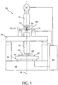
- a microlithographic projection system 10 as an example of a projection system capable of benefitting from the invention, includes a light source 12, an illuminator 14, and a projection lens 16 for projecting an image of a reticle 18 onto a substrate 20.
- a horizontal X-Y-axis stage 22, which is translatable in two orthogonal directions normal to a common optical axis 24 of the illuminator 14 and the projection lens 16, provides for relatively moving the substrate 20 with respect to the projection lens 16 for exposing successive areas of the substrate 20.
- a vertical Z-axis stage 26 provides for relatively translating the projection lens 16 with respect to the substrate 20 along the optical axis 24 to provide for appropriately focusing the image of the reticle 18 onto the substrate 20.
- the light source 12 can take a variety of forms for emitting radiation in the form of a beam of light 28 appropriate for developing the photosensitive substrate 20.
- the light source 12 can be a lamp source such as a high-pressure mercury arc lamp targeting certain spectral lines or a laser source, such as an excimer laser, particularly for operating within the deep ultraviolet spectrum.
- the illuminator 14 provides for shaping and spatially distributing the light beam 28 and targeting angular and spatial irradiance profiles set for both the pupil and image plane of the projection lens, the latter coinciding with the substrate 20.
- typical illuminators for microlithographic operations include a profiler for collecting and shaping the beam 28, a uniformizer (e.g., a kaleidoscope or fly's eye array) for integrating the light into a uniform irradiance field, and a relay lens for relaying an image of the output of the uniformizer to the reticle 18, where an image plane of the illuminator 14 coincides with an object plane of the projection lens 16.
- a uniformizer e.g., a kaleidoscope or fly's eye array
- the projection lens 16 which preferably has an entrance numerical aperture larger than an exit numerical aperture of the illuminator 14 for providing partial coherent imaging, projects an image of the reticle 18 onto the substrate 20. That is, a pupil (not shown) of the projection lens 16, which is typically conjugate to a pupil (also not shown) in the illuminator 14, is preferably underfilled by the image of the illuminator pupil but is sized to collect angularly divergent light from illuminated features of the reticle 18 to produce a high resolution image of the reticle 18 on the substrate 20.
- the projected image of the reticle 18 can be enlarged or reduced as required.
- the projection lens 16 can include reflective or diffractive elements as well as refractive elements or combinations of such elements, such as in catadioptric optics.
- the reticle 18, also referred to as a "mask”, includes one or more patterns intended for projection onto the substrate 20 and can be sized within or beyond the size of the entrance pupil of the projector lens 16. Reticles with larger patterns can be relatively translated with respect to the projection lenses to expose different parts of the reticle patterns in succession.
- the photosensitive substrate 20 generally takes the form of a flat plate, such as a semiconductor wafer or glass panel treated with a photoresist to react to exposures of light. Often, the entire substrate 20 cannot be imaged at once, so the horizontal X-Y-axis translational stage 22 on a base 30 provides for translating the substrate 20 through a range of positions for collectively illuminating a desired working area of the substrate 20.
- the projection lens 16 is supported on the vertical Z-axis translational stage 26 above the base 30 for adjusting the image distance of the projection lens 16 from the substrate 20 along the optical axis 24.
- a controller 32 coordinates relative motions between the projection lens 16, the reticle 18, and the substrate 20 as well as the exposure of the projection system 10.
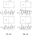
- a telecentricity corrector 40 is positioned within an image space 42 of the illuminator 14 as close as possible to the reticle 18 for redistributing the illuminator's angular irradiance within an adjoining object space 44 of the projection lens 16 to assure that the projection system 10 is telecentric at least within an image space 46 of the projection lens 16. Absent, the telecentric corrector 40, as depicted in FIG.
- a nominally telecentric irradiance within the adjoining image space 42 of the illuminator 14 and object space 44 of the projection lens 16 results in a non-linear departure from telecentricity in the image space 46 of the projection lens 16 (depicted as variously askew cones of light 56 forming corresponding image points 58 on a photosensitive surface 50 of the substrate 20 - the image plane of the projection lens 16).
- the departure from telecentricity varies in both magnitude and direction across the surface 50 of the substrate 20.
- the patterned surface 48 of the reticle 18 is shown on the top surface of the reticle, the patterned surface 48 could also be located on the bottom surface of the reticle 18 as is often the case for protecting the patterned surface 48 and reducing the amount of glass through which the projection lens 16 is required to operate. Whether located on the top or the bottom surface of the reticle, the patterned surface 48 is preferably also located at the image plane of the illuminator 14 and object plane or the projection lens 16.
- the telecentricity corrector 40 compensates the apparent errors or design limitations within the projection lens 16 or reticle 18 by locally redistributing the angular irradiance distribution of the illuminator 14 in advance of the reticle 18 (depicted as variously askew cones of light 62 illuminating individual object points 64 on the surface 48 of the reticle 18) so that each feature on the reticle 18 is imaged telecentrically at the substrate 20 (depicted as vertically oriented cones of light 66 forming corresponding image points 68 on the surface 50 of the substrate 20).
- the telecentricity corrector 40 can similarly compensate for errors or design limitations within the illuminator 14, which result in or otherwise contribute to higher order departures from telecentricity within the image space 46 of the projection lens 16.
- the telecentricity corrector 40 has a substantially planar body 72 with a corrective surface 74 that departs from a planar form.
- the adjustments to the angular irradiance distributions of the illuminator 14 can be made by shaping the corrective surface 74 to include local slope variations (depicted as the angle ⁇ ) for bending rays in differing amounts and directions across the field of illumination.
- the local slope ⁇ on the corrective surface 74 can be regarded as a first derivative of the sag of an aspheric surface.
- the additional freedoms made possible by the higher-order changes to the corrective surface 74 can be incorporated into standard lens defining code for optimizing the local slope variations across the corrective surface 74. For example, such design freedoms can be optimized within Code V optical design software available from Optical research associates headquartered in Pasadena, California.
- the rates of change in slope ( ⁇ ) from point to point across the corrective surface 74 which can be regarded as a second derivative of the sag of the aspheric surface, produce localized optical power variations that affect the irradiance uniformity across the image plane 50 of the projection lens 16.
- the optical power variations for locally converging or diverging light operate through an offset distance between the corrective surface 74 and the patterned surface 48 of the reticle 18, coinciding with the image plane of the illuminator 14 and the object plane of the projection lens 16.
- the local irradiance distribution effects at the patterned surface are proportional to the distance the corrective surface 74 is offset from the patterned surface 48.
- the resolution with which the angular and spatial corrections can be made at the patterned surface 48 is inversely proportional to the offset distance.
- the design of the telecentricity corrector 40 is preferably optimized for balancing the requirements for telecentricity and uniformity at the image plane 50 of the projection lens 16.
- improvements can be made to both telecentricity and uniformity at the image plane 50.
- the projection lens 16 could be designed to be doubly telecentric (i.e., telecentric in both its object space 44 and image space 46) or to depart in a prescribed manner from telecentricity in the object space 44 for such purposes as supporting subsequent adjustments to magnification or distortion.
- Co-owned International Application No. PCT/US2007/01 0044 filed on April 26, 2007 , and published as WO 2007/130299 entering the US national stage as Application No. 11/922,18 on December 12, 2007 , exploits a non-linear variation in object plane telecentricity to provide adjustments to distortion and magnification. Desired telecentricity departures within the image plane 50 of the projection lens 16 to serve particular purposes can be similarly accommodated as targets of the design optimization.
- the telecentricity corrector 40 can be used to compensate for systematic errors or alternative performance targets arising after the projection system 10 is built.
- telecentricity or uniformity errors regardless of their source, can be empirically measured and used as a basis for designing or redesigning the telecentricity corrector 40.
- the spatial or angular departures from the desired irradiance distribution can be measured at the image plane 50 of the projection lens 16 directly or inferred from errors associated with the exposure of known patterns on the substrate 20.
- the measured errors requiring compensation by the telecentricity corrector 40 can be incorporated into the conventional design software as targets of opposite sign.
- the telecentricity corrector 40 is shown as a nominally planar refractive optic having a single corrective surface subject to higher order variations in slope, the telecentricity corrector 40 could also be incorporated into refractive optics of different shape or non-refractive optics, such as reflective or diffractive optics. Gradient index variations could also be used in place of or in addition to surface form modifications for making the local redirections of light. Both entrance and exit surfaces can be used to contribute to the desired corrections. More than one telecentricity corrector could also be used, such as one corrector for incorporation into the original design and another corrector to compensate for later-measured errors. Preferably, the telecentricity corrector is incorporated into the design as an additional optical element, but the telecentricity correction could also be incorporated into an existing element of the design, such as by modifying the surface of an otherwise planar or spherical optic.
- the telecentricity corrector 40 is preferably located as close as possible to the reticle 18 while accommodating mechanical constraints such as requirements for adjusting or replacing the reticle or clearance required protecting the reticle from environmental damage
- the telecentricity corrector 40 could alternatively be located within an illuminator plane that is conjugate to the reticle 18, such as a plane adjacent to the output of the uniformizer.
- Separate telecentricity correctors could be located in each of the two or more conjugate planes to better meet the targets for telecentricity and uniformity at the image plane of the projection lens 16 as well as other targets for telecentricity or uniformity elsewhere in the design, such as at the object plane of the projection lens 16.
- FIG. 4 illustrates the combination of two corrector plates 80 and 90 having respective aspheric corrective surfaces 82 and 92 formed in refractive bodies 84 and 94.
- the corrective surface 92 of the corrector 90 is located as close as possible to the patterned surface 48 of the reticle 18 for influencing telecentricity at the patterned surface 48 (i.e., at the image plane of the illuminator 14 and object plane of the projection lens 16) to a high resolution while having a minimal effect on the irradiance distribution at the patterned surface 48.
- the corrective surface 82 of the corrector 80 is located through an offset distance "D" from the patterned surface 48 for influencing both irradiance uniformity and telecentricity at the patterned surface 48.
- Local curvatures of the corrective surface 82 of the corrector 80 can be optimized to provide a desired irradiance distribution at the patterned surface 48.
- Local slopes of the corrective surface 92 of the corrector 90 can be optimized to provide the desired telecentricity at the patterned surface 48 while compensating for any unwanted telecentricity effects of the corrective surface 82.
- the corrective surfaces 82 and 92 can be optimized to achieve both the desired telecentricity and the desired irradiance distribution at the image plane of the illuminator 14 at which the patterned surface 48 of the reticle 18 is located.
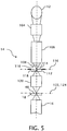
- an alternative corrective optic 112 can be positioned with its corrective surface 114 at a uniform plane 116 conjugate to the image plane 122 of the illuminator 14 to provide for correcting telecentricity independently of irradiance uniformity.
- the illuminator 14 as depicted in further detail in FIG. 5 includes a beam profiler 104 for shaping light from the light source 12 and for filling a uniformizer 106 that integrates the light into a uniform plane 116 containing field stop 118.
- a relay lens 120 images the field stop 118 onto the uniform image plane 122 of the illuminator 14, which is coincident with an object plane 124 of the projection lens 16.
- the patterned surface 48 of the reticle 18 is located at the coincident image and object planes 122 and 124 of the illuminator 12 and the projection lens 14.
- the corrective surface 114 of the corrective optic 112 is located at the conjugate uniform plane 116 for similarly influencing telecentricity at both the conjugate uniform plane 116 and the coincident image and object planes 122 and 124 independently of irradiance uniformity at the same image and object planes 122 and 124.
- a second corrective optic 108 includes a corrective surface 110 that is located offset from the conjugate plane 116 for influencing the irradiance distribution at both the conjugate uniform plane 116 and the coincident image and object planes 122 and 124.
- the second corrective optic 108 is preferably located between the uniformizer 106 and conjugate uniform plane 116 so as not to interfere with the imaging of the field stop 118, the second corrective optic 108 could also be located between the conjugate uniform plane 116 and the relay lens 120 because of the lower requirements for imaging within the illuminator 14 or in the illuminator image space between the relay lens 120 and the image plane 122.
- corrective surfaces 82 and 92 of the corrective optics 80 and 90 of FIG. 4 and the corrective surfaces 110 and 114 of the corrective optics 108 and 112 are shown as being fashioned on different refractive bodies (e.g., 84 and 88), the corrective surfaces 82, 92 and 110, 114 could be fashioned on opposite sides of single refractive bodies.
- the corrective surfaces 92 or 114 are preferably located as close a possible to the image plane 122 of the illuminator 14 or to the conjugate plane 116 within the illuminator 14 while the corrective surfaces 82 and 110 are offset through the thickness of the single refractive bodies.
Claims (10)
- Lithografisches Projektionssystem, umfassend:einen Illuminator (14) für den Empfang von Licht von einer Lichtquelle, um ein Fadenkreuz auf einer Bildebene des Illuminators zu beleuchten;eine Projektionslinse (16) zum Projizieren eines Bilds des Fadenkreuzes auf ein Substrat; undeinen Telezentrizitätsregler (40), der proximal zu der Bildebene oder einem Konjugat der Bildebene des Illuminators angeordnet ist, um lokale Winkelneuverteilungen des das Fadenkreuz beleuchtenden Lichts vorzunehmen, um Zielspezifikationen für Telezentrizität auf dem Substrat zu erfüllen;dadurch gekennzeichnet, dass der Telezentrizitätsregler (40) eine korrigierende Oberfläche (74, 82, 92, 114) mit lokalen Steigungsvariationen für die Ausführung der lokalen Winkelneuverteilungen von Licht aufweist, wobei die Raten der Variation der lokalen Steigung so angepasst werden, dass die Strahlungseinheitlichkeit auf dem Substrat geregelt wird.
- Projektionssystem nach Anspruch 1, wobei der Telezentrizitätsregler (40) im Wesentlichen angrenzend an oder konjugiert zu dem Fadenkreuz angeordnet ist.
- Projektionssystem nach Anspruch 1, wobei der Telezentrizitätsregler (40) die Durchführung lokaler räumlicher Neuverteilungen von das Fadenkreuz beleuchtendem Licht bereitstellt.
- Projektionssystem nach Anspruch 1, wobei der Telezentrizitätsregler (40) eine erste korrigierende Oberfläche (92) aufweist, die proximal zu der Bildebene oder einem Konjugat der Bildebene des Illuminators angeordnet ist, und eine zweite korrigierende Oberfläche (82), die von der Bildebene oder einem Konjugat der Bildebene des Illuminators versetzt ist.
- Projektionssystem nach Anspruch 1, wobei der Telezentrizitätsregler (40) erste und zweite korrigierende Oberflächen aufweist, wobei die erste korrigierende Oberfläche (92) so angeordnet ist, dass sie lokale Winkelneuverteilungen von Licht durch die zweite korrigierende Oberfläche (82) kompensiert, um Zielspezifikationen für die Telezentrizität auf dem Substrat zu erfüllen.
- Projektionssystem nach Anspruch 1, wobei der Telezentrizitätsregler (40) lokale Brechungsindexvariationen für die Durchführung der lokalen Winkelneuverteilungen von Licht und Änderungsraten der lokalen Brechungsindexvariationen zur Regelung der Strahlungseinheitlichkeit auf dem Substrat aufweist.
- Verfahren zur Kompensation empirisch gemessener Fehler in einem lithografischen Projektionssystem, das einen Illuminator (14) und eine Projektionslinse (16) aufweist, die folgenden Schritte umfassend:Identifizieren von Telezentrizitätsfehlern auf einer Bildebene der Projektionslinse (16);Identifizieren von Fehler der Strahlungseinheitlichkeit auf der Bildebene der Projektionslinse (16);Festlegen überarbeiteter Telezentrizitätsziele auf einer Bildebene des Illuminators, um die identifizierten Telezentrizitätsfehler zu kompensieren;Festlegen überarbeiteter Einheitlichkeitsziele auf der Bildebene des Illuminators, um die identifizierten Fehler der Strahlungseinheitlichkeit zu kompensieren;Inkorporieren lokaler Variationen in einem Telezentrizitätsregler (40), der proximal zu der Bildebene oder einem Konjugat der Bildebene des Illuminators angeordnet ist, um überarbeitete Telezentrizitätsziele zu erfüllen; undInkorporieren von Änderungsraten in den lokalen Variationen in dem Telezentrizitätsregler (40), um die überarbeiteten Ziele für die Strahlungseinheitlichkeit zu erfüllen.
- Verfahren nach Anspruch 7, wobei der Telezentrizitätsregler eine korrigierende Oberfläche (74, 82, 92, 114) aufweist, und wobei die Schritte des Inkorporierens der Variationen die Regelung lokaler Steigungsvariationen in der korrigierenden Oberfläche beinhalten, um die überarbeiteten Telezentrizitätsziele zu erreichen.
- Verfahren nach Anspruch 8, ferner umfassend das Regeln der Änderungsraten der lokalen Steigungsvariationen in der korrigierenden Oberfläche, um die Ziele für die Strahlungseinheitlichkeit auf dem Substrat zu erreichen.
- Verfahren nach Anspruch 7, wobei der Telezentrizitätsregler (40) erste und zweite korrigierende Oberflächen (92, 82) aufweist, die entsprechend auf ausgebildet sind auf wenigstens einem der folgenden: (a) auf einer Seite von zwei Korrektionsoptiken und (b) auf zwei Seiten einer Korrektionsoptik.
Applications Claiming Priority (2)
| Application Number | Priority Date | Filing Date | Title |
|---|---|---|---|
| US7688808P | 2008-06-30 | 2008-06-30 | |
| PCT/US2009/003795 WO2010005491A1 (en) | 2008-06-30 | 2009-06-25 | Telecentricity corrector for microlithographic projection system |
Publications (2)
| Publication Number | Publication Date |
|---|---|
| EP2310914A1 EP2310914A1 (de) | 2011-04-20 |
| EP2310914B1 true EP2310914B1 (de) | 2018-12-26 |
Family
ID=41168460
Family Applications (1)
| Application Number | Title | Priority Date | Filing Date |
|---|---|---|---|
| EP09788838.2A Active EP2310914B1 (de) | 2008-06-30 | 2009-06-25 | Telezentrizitätskorrektor für mikrolithografisches projektionssystem |
Country Status (6)
| Country | Link |
|---|---|
| US (1) | US8314922B2 (de) |
| EP (1) | EP2310914B1 (de) |
| JP (1) | JP5763534B2 (de) |
| KR (1) | KR101624758B1 (de) |
| CN (1) | CN102077143B (de) |
| WO (1) | WO2010005491A1 (de) |
Families Citing this family (13)
| Publication number | Priority date | Publication date | Assignee | Title |
|---|---|---|---|---|
| JP5763534B2 (ja) * | 2008-06-30 | 2015-08-12 | コーニング インコーポレイテッド | マイクロリソグラフィック投影システムのためのテレセントリシティ補正素子 |
| TWI654419B (zh) | 2011-08-29 | 2019-03-21 | 美商安美基公司 | 用於非破壞性檢測-流體中未溶解粒子之方法及裝置 |
| JP6147058B2 (ja) * | 2013-04-01 | 2017-06-14 | キヤノン株式会社 | ノズルチップの製造方法 |
| US9188767B2 (en) | 2013-11-04 | 2015-11-17 | Christie Digital Systems Usa, Inc. | Relay lens system for a high dynamic range projector |
| US9232172B2 (en) | 2013-11-04 | 2016-01-05 | Christie Digital Systems Usa, Inc. | Two-stage light modulation for high dynamic range |
| JP2018519535A (ja) * | 2015-05-21 | 2018-07-19 | カール・ツァイス・エスエムティー・ゲーエムベーハー | マイクロリソグラフィ投影装置を作動させる方法 |
| US10088660B2 (en) | 2017-02-10 | 2018-10-02 | Amgen Inc. | Imaging system for counting and sizing particles in fluid-filled vessels |
| JP2018151832A (ja) * | 2017-03-13 | 2018-09-27 | キヤノン株式会社 | 情報処理装置、情報処理方法、および、プログラム |
| JP2019079029A (ja) * | 2017-10-24 | 2019-05-23 | キヤノン株式会社 | 露光装置および物品の製造方法 |
| WO2019082727A1 (ja) * | 2017-10-24 | 2019-05-02 | キヤノン株式会社 | 露光装置および物品の製造方法 |
| EP3486866A1 (de) * | 2017-11-15 | 2019-05-22 | Thomson Licensing | Verfahren zur verarbeitung eines lichtfeldvideos basierend auf der verwendung einer superstrahlendarstellung |
| WO2021045685A1 (en) * | 2019-09-04 | 2021-03-11 | Ams Sensors Singapore Pte. Ltd. | Designing and constructing dot projectors for three-dimensional sensor modules |
| CN113552774A (zh) * | 2020-04-23 | 2021-10-26 | 上海微电子装备(集团)股份有限公司 | 照明光学系统、光刻机设备及曝光方法 |
Citations (1)
| Publication number | Priority date | Publication date | Assignee | Title |
|---|---|---|---|---|
| US6522386B1 (en) * | 1997-07-24 | 2003-02-18 | Nikon Corporation | Exposure apparatus having projection optical system with aberration correction element |
Family Cites Families (15)
| Publication number | Priority date | Publication date | Assignee | Title |
|---|---|---|---|---|
| JPS62266513A (ja) * | 1986-05-14 | 1987-11-19 | Canon Inc | 投影露光光学系 |
| US5461456A (en) * | 1992-11-24 | 1995-10-24 | General Signal Corporation | Spatial uniformity varier for microlithographic illuminator |
| US5995263A (en) * | 1993-11-12 | 1999-11-30 | Nikon Corporation | Projection exposure apparatus |
| KR960042227A (ko) * | 1995-05-19 | 1996-12-21 | 오노 시게오 | 투영노광장치 |
| JP2000195778A (ja) | 1998-12-28 | 2000-07-14 | Nikon Corp | 露光装置及びテレセントリシティ―ムラ補正部材の製造方法 |
| TWI283798B (en) * | 2000-01-20 | 2007-07-11 | Asml Netherlands Bv | A microlithography projection apparatus |
| JP2002184676A (ja) * | 2000-12-18 | 2002-06-28 | Nikon Corp | 照明光学装置および該照明光学装置を備えた露光装置 |
| JP2003203844A (ja) * | 2002-01-08 | 2003-07-18 | Nikon Corp | 投影露光装置及び露光方法 |
| DE102004035595B4 (de) * | 2004-04-09 | 2008-02-07 | Carl Zeiss Smt Ag | Verfahren zur Justage eines Projektionsobjektives |
| JP4599936B2 (ja) * | 2004-08-17 | 2010-12-15 | 株式会社ニコン | 照明光学装置、照明光学装置の調整方法、露光装置、および露光方法 |
| WO2006029796A2 (en) * | 2004-09-13 | 2006-03-23 | Carl Zeiss Smt Ag | Microlithographic projection exposure apparatus |
| US7508489B2 (en) * | 2004-12-13 | 2009-03-24 | Carl Zeiss Smt Ag | Method of manufacturing a miniaturized device |
| US20090021830A1 (en) * | 2005-09-14 | 2009-01-22 | Carl Zeiss Smt Ag | Projection lens of a microlithographic exposure system |
| EP2016455A2 (de) | 2006-05-05 | 2009-01-21 | Corning Incorporated | Verzerrungseinstellung einer beinahe telezentrischen bildgebundslinse |
| JP5763534B2 (ja) * | 2008-06-30 | 2015-08-12 | コーニング インコーポレイテッド | マイクロリソグラフィック投影システムのためのテレセントリシティ補正素子 |
-
2009
- 2009-06-25 JP JP2011516307A patent/JP5763534B2/ja active Active
- 2009-06-25 KR KR1020117002297A patent/KR101624758B1/ko active IP Right Grant
- 2009-06-25 WO PCT/US2009/003795 patent/WO2010005491A1/en active Application Filing
- 2009-06-25 EP EP09788838.2A patent/EP2310914B1/de active Active
- 2009-06-25 CN CN200980126128.XA patent/CN102077143B/zh active Active
- 2009-06-30 US US12/494,882 patent/US8314922B2/en active Active
Patent Citations (1)
| Publication number | Priority date | Publication date | Assignee | Title |
|---|---|---|---|---|
| US6522386B1 (en) * | 1997-07-24 | 2003-02-18 | Nikon Corporation | Exposure apparatus having projection optical system with aberration correction element |
Also Published As
| Publication number | Publication date |
|---|---|
| WO2010005491A1 (en) | 2010-01-14 |
| US20090323040A1 (en) | 2009-12-31 |
| CN102077143B (zh) | 2014-01-22 |
| EP2310914A1 (de) | 2011-04-20 |
| US8314922B2 (en) | 2012-11-20 |
| JP5763534B2 (ja) | 2015-08-12 |
| KR101624758B1 (ko) | 2016-05-26 |
| KR20110026496A (ko) | 2011-03-15 |
| JP2011527024A (ja) | 2011-10-20 |
| CN102077143A (zh) | 2011-05-25 |
Similar Documents
| Publication | Publication Date | Title |
|---|---|---|
| EP2310914B1 (de) | Telezentrizitätskorrektor für mikrolithografisches projektionssystem | |
| US8922750B2 (en) | Magnification control for lithographic imaging system | |
| US10101666B2 (en) | Illumination optical apparatus, exposure apparatus, and device manufacturing method | |
| US8605249B2 (en) | Exposure apparatus, exposure method, and device manufacturing method | |
| TW591694B (en) | Specification determining method, making method and adjusting method of projection optical system, exposure apparatus and making method thereof, and computer system | |
| US7403262B2 (en) | Projection optical system and exposure apparatus having the same | |
| KR101401227B1 (ko) | 편향 미러를 포함하는 반사 굴절식 투영 대물 렌즈 및 투영 노광 방법 | |
| JP2013511843A5 (de) | ||
| JP2007013179A (ja) | リソグラフィ投影対物レンズの補正方法およびリソグラフィ投影対物レンズ | |
| CN103488061B (zh) | 极紫外光刻机中匹配多个物镜的照明系统调整与设计方法 | |
| US10191387B2 (en) | Reflective mirror, projection optical system, exposure apparatus, and device manufacturing method | |
| JP2007194600A (ja) | リソグラフィ装置およびデバイス製造方法 | |
| JP2002118053A (ja) | 投影光学系,該投影光学系を備えた露光装置,及び該露光装置を用いたデバイスの製造方法 | |
| US7522260B1 (en) | Method for correcting astigmatism in a microlithography projection exposure apparatus, a projection objective of such a projection exposure apparatus, and a fabrication method for micropatterned components | |
| JP2003295021A (ja) | 光学系の組み立て調整方法及び光学系の製造方法 | |
| JP2010272631A (ja) | 照明装置、露光装置、及びデバイス製造方法 | |
| US7068349B2 (en) | Method of and preventing focal plane anomalies in the focal plane of a projection system | |
| TW517280B (en) | Projection optical system, exposure device and the manufacturing method thereof | |
| JP2009117672A (ja) | 照明光学系、露光装置、およびデバイス製造方法 | |
| JP2013098208A (ja) | 照明光学系、露光装置、デバイス製造方法、および照明方法 | |
| JP2013165196A (ja) | 照明光学系、露光装置、およびデバイス製造方法 | |
| JP2011009317A (ja) | オプティカルインテグレータ、照明光学系、露光装置、およびデバイス製造方法 |
Legal Events
| Date | Code | Title | Description |
|---|---|---|---|
| PUAI | Public reference made under article 153(3) epc to a published international application that has entered the european phase |
Free format text: ORIGINAL CODE: 0009012 |
|
| 17P | Request for examination filed |
Effective date: 20110120 |
|
| AK | Designated contracting states |
Kind code of ref document: A1 Designated state(s): AT BE BG CH CY CZ DE DK EE ES FI FR GB GR HR HU IE IS IT LI LT LU LV MC MK MT NL NO PL PT RO SE SI SK TR |
|
| AX | Request for extension of the european patent |
Extension state: AL BA RS |
|
| RIN1 | Information on inventor provided before grant (corrected) |
Inventor name: WEBB, JAMES, E. Inventor name: CORNELL, JIM, D. Inventor name: MICHALOSKI, PAUL, F. Inventor name: MALACH, JOSEPH, D. |
|
| DAX | Request for extension of the european patent (deleted) | ||
| 17Q | First examination report despatched |
Effective date: 20120720 |
|
| RIC1 | Information provided on ipc code assigned before grant |
Ipc: G02B 27/00 20060101ALI20180625BHEP Ipc: G03F 7/20 20060101AFI20180625BHEP Ipc: G02B 27/42 20060101ALI20180625BHEP Ipc: G02B 13/22 20060101ALI20180625BHEP |
|
| GRAP | Despatch of communication of intention to grant a patent |
Free format text: ORIGINAL CODE: EPIDOSNIGR1 |
|
| STAA | Information on the status of an ep patent application or granted ep patent |
Free format text: STATUS: GRANT OF PATENT IS INTENDED |
|
| INTG | Intention to grant announced |
Effective date: 20180824 |
|
| GRAS | Grant fee paid |
Free format text: ORIGINAL CODE: EPIDOSNIGR3 |
|
| GRAA | (expected) grant |
Free format text: ORIGINAL CODE: 0009210 |
|
| STAA | Information on the status of an ep patent application or granted ep patent |
Free format text: STATUS: THE PATENT HAS BEEN GRANTED |
|
| AK | Designated contracting states |
Kind code of ref document: B1 Designated state(s): AT BE BG CH CY CZ DE DK EE ES FI FR GB GR HR HU IE IS IT LI LT LU LV MC MK MT NL NO PL PT RO SE SI SK TR |
|
| REG | Reference to a national code |
Ref country code: GB Ref legal event code: FG4D |
|
| REG | Reference to a national code |
Ref country code: CH Ref legal event code: EP |
|
| REG | Reference to a national code |
Ref country code: AT Ref legal event code: REF Ref document number: 1082220 Country of ref document: AT Kind code of ref document: T Effective date: 20190115 |
|
| REG | Reference to a national code |
Ref country code: DE Ref legal event code: R096 Ref document number: 602009056416 Country of ref document: DE |
|
| REG | Reference to a national code |
Ref country code: IE Ref legal event code: FG4D |
|
| REG | Reference to a national code |
Ref country code: NL Ref legal event code: FP |
|
| PG25 | Lapsed in a contracting state [announced via postgrant information from national office to epo] |
Ref country code: FI Free format text: LAPSE BECAUSE OF FAILURE TO SUBMIT A TRANSLATION OF THE DESCRIPTION OR TO PAY THE FEE WITHIN THE PRESCRIBED TIME-LIMIT Effective date: 20181226 Ref country code: LT Free format text: LAPSE BECAUSE OF FAILURE TO SUBMIT A TRANSLATION OF THE DESCRIPTION OR TO PAY THE FEE WITHIN THE PRESCRIBED TIME-LIMIT Effective date: 20181226 Ref country code: BG Free format text: LAPSE BECAUSE OF FAILURE TO SUBMIT A TRANSLATION OF THE DESCRIPTION OR TO PAY THE FEE WITHIN THE PRESCRIBED TIME-LIMIT Effective date: 20190326 Ref country code: HR Free format text: LAPSE BECAUSE OF FAILURE TO SUBMIT A TRANSLATION OF THE DESCRIPTION OR TO PAY THE FEE WITHIN THE PRESCRIBED TIME-LIMIT Effective date: 20181226 Ref country code: LV Free format text: LAPSE BECAUSE OF FAILURE TO SUBMIT A TRANSLATION OF THE DESCRIPTION OR TO PAY THE FEE WITHIN THE PRESCRIBED TIME-LIMIT Effective date: 20181226 Ref country code: NO Free format text: LAPSE BECAUSE OF FAILURE TO SUBMIT A TRANSLATION OF THE DESCRIPTION OR TO PAY THE FEE WITHIN THE PRESCRIBED TIME-LIMIT Effective date: 20190326 |
|
| REG | Reference to a national code |
Ref country code: LT Ref legal event code: MG4D |
|
| PG25 | Lapsed in a contracting state [announced via postgrant information from national office to epo] |
Ref country code: GR Free format text: LAPSE BECAUSE OF FAILURE TO SUBMIT A TRANSLATION OF THE DESCRIPTION OR TO PAY THE FEE WITHIN THE PRESCRIBED TIME-LIMIT Effective date: 20190327 Ref country code: SE Free format text: LAPSE BECAUSE OF FAILURE TO SUBMIT A TRANSLATION OF THE DESCRIPTION OR TO PAY THE FEE WITHIN THE PRESCRIBED TIME-LIMIT Effective date: 20181226 |
|
| REG | Reference to a national code |
Ref country code: AT Ref legal event code: MK05 Ref document number: 1082220 Country of ref document: AT Kind code of ref document: T Effective date: 20181226 |
|
| PG25 | Lapsed in a contracting state [announced via postgrant information from national office to epo] |
Ref country code: IT Free format text: LAPSE BECAUSE OF FAILURE TO SUBMIT A TRANSLATION OF THE DESCRIPTION OR TO PAY THE FEE WITHIN THE PRESCRIBED TIME-LIMIT Effective date: 20181226 Ref country code: CZ Free format text: LAPSE BECAUSE OF FAILURE TO SUBMIT A TRANSLATION OF THE DESCRIPTION OR TO PAY THE FEE WITHIN THE PRESCRIBED TIME-LIMIT Effective date: 20181226 Ref country code: PT Free format text: LAPSE BECAUSE OF FAILURE TO SUBMIT A TRANSLATION OF THE DESCRIPTION OR TO PAY THE FEE WITHIN THE PRESCRIBED TIME-LIMIT Effective date: 20190426 Ref country code: ES Free format text: LAPSE BECAUSE OF FAILURE TO SUBMIT A TRANSLATION OF THE DESCRIPTION OR TO PAY THE FEE WITHIN THE PRESCRIBED TIME-LIMIT Effective date: 20181226 Ref country code: PL Free format text: LAPSE BECAUSE OF FAILURE TO SUBMIT A TRANSLATION OF THE DESCRIPTION OR TO PAY THE FEE WITHIN THE PRESCRIBED TIME-LIMIT Effective date: 20181226 |
|
| PG25 | Lapsed in a contracting state [announced via postgrant information from national office to epo] |
Ref country code: SK Free format text: LAPSE BECAUSE OF FAILURE TO SUBMIT A TRANSLATION OF THE DESCRIPTION OR TO PAY THE FEE WITHIN THE PRESCRIBED TIME-LIMIT Effective date: 20181226 Ref country code: EE Free format text: LAPSE BECAUSE OF FAILURE TO SUBMIT A TRANSLATION OF THE DESCRIPTION OR TO PAY THE FEE WITHIN THE PRESCRIBED TIME-LIMIT Effective date: 20181226 Ref country code: RO Free format text: LAPSE BECAUSE OF FAILURE TO SUBMIT A TRANSLATION OF THE DESCRIPTION OR TO PAY THE FEE WITHIN THE PRESCRIBED TIME-LIMIT Effective date: 20181226 Ref country code: IS Free format text: LAPSE BECAUSE OF FAILURE TO SUBMIT A TRANSLATION OF THE DESCRIPTION OR TO PAY THE FEE WITHIN THE PRESCRIBED TIME-LIMIT Effective date: 20190426 |
|
| REG | Reference to a national code |
Ref country code: DE Ref legal event code: R097 Ref document number: 602009056416 Country of ref document: DE |
|
| PG25 | Lapsed in a contracting state [announced via postgrant information from national office to epo] |
Ref country code: AT Free format text: LAPSE BECAUSE OF FAILURE TO SUBMIT A TRANSLATION OF THE DESCRIPTION OR TO PAY THE FEE WITHIN THE PRESCRIBED TIME-LIMIT Effective date: 20181226 Ref country code: DK Free format text: LAPSE BECAUSE OF FAILURE TO SUBMIT A TRANSLATION OF THE DESCRIPTION OR TO PAY THE FEE WITHIN THE PRESCRIBED TIME-LIMIT Effective date: 20181226 |
|
| PLBE | No opposition filed within time limit |
Free format text: ORIGINAL CODE: 0009261 |
|
| STAA | Information on the status of an ep patent application or granted ep patent |
Free format text: STATUS: NO OPPOSITION FILED WITHIN TIME LIMIT |
|
| 26N | No opposition filed |
Effective date: 20190927 |
|
| PG25 | Lapsed in a contracting state [announced via postgrant information from national office to epo] |
Ref country code: MC Free format text: LAPSE BECAUSE OF FAILURE TO SUBMIT A TRANSLATION OF THE DESCRIPTION OR TO PAY THE FEE WITHIN THE PRESCRIBED TIME-LIMIT Effective date: 20181226 |
|
| REG | Reference to a national code |
Ref country code: CH Ref legal event code: PL |
|
| GBPC | Gb: european patent ceased through non-payment of renewal fee |
Effective date: 20190625 |
|
| PG25 | Lapsed in a contracting state [announced via postgrant information from national office to epo] |
Ref country code: SI Free format text: LAPSE BECAUSE OF FAILURE TO SUBMIT A TRANSLATION OF THE DESCRIPTION OR TO PAY THE FEE WITHIN THE PRESCRIBED TIME-LIMIT Effective date: 20181226 |
|
| REG | Reference to a national code |
Ref country code: BE Ref legal event code: MM Effective date: 20190630 |
|
| PG25 | Lapsed in a contracting state [announced via postgrant information from national office to epo] |
Ref country code: TR Free format text: LAPSE BECAUSE OF FAILURE TO SUBMIT A TRANSLATION OF THE DESCRIPTION OR TO PAY THE FEE WITHIN THE PRESCRIBED TIME-LIMIT Effective date: 20181226 |
|
| PG25 | Lapsed in a contracting state [announced via postgrant information from national office to epo] |
Ref country code: GB Free format text: LAPSE BECAUSE OF NON-PAYMENT OF DUE FEES Effective date: 20190625 Ref country code: IE Free format text: LAPSE BECAUSE OF NON-PAYMENT OF DUE FEES Effective date: 20190625 |
|
| PG25 | Lapsed in a contracting state [announced via postgrant information from national office to epo] |
Ref country code: LI Free format text: LAPSE BECAUSE OF NON-PAYMENT OF DUE FEES Effective date: 20190630 Ref country code: CH Free format text: LAPSE BECAUSE OF NON-PAYMENT OF DUE FEES Effective date: 20190630 Ref country code: BE Free format text: LAPSE BECAUSE OF NON-PAYMENT OF DUE FEES Effective date: 20190630 Ref country code: LU Free format text: LAPSE BECAUSE OF NON-PAYMENT OF DUE FEES Effective date: 20190625 |
|
| PG25 | Lapsed in a contracting state [announced via postgrant information from national office to epo] |
Ref country code: FR Free format text: LAPSE BECAUSE OF NON-PAYMENT OF DUE FEES Effective date: 20190630 |
|
| PG25 | Lapsed in a contracting state [announced via postgrant information from national office to epo] |
Ref country code: CY Free format text: LAPSE BECAUSE OF FAILURE TO SUBMIT A TRANSLATION OF THE DESCRIPTION OR TO PAY THE FEE WITHIN THE PRESCRIBED TIME-LIMIT Effective date: 20181226 |
|
| PG25 | Lapsed in a contracting state [announced via postgrant information from national office to epo] |
Ref country code: HU Free format text: LAPSE BECAUSE OF FAILURE TO SUBMIT A TRANSLATION OF THE DESCRIPTION OR TO PAY THE FEE WITHIN THE PRESCRIBED TIME-LIMIT; INVALID AB INITIO Effective date: 20090625 Ref country code: MT Free format text: LAPSE BECAUSE OF FAILURE TO SUBMIT A TRANSLATION OF THE DESCRIPTION OR TO PAY THE FEE WITHIN THE PRESCRIBED TIME-LIMIT Effective date: 20181226 |
|
| PG25 | Lapsed in a contracting state [announced via postgrant information from national office to epo] |
Ref country code: MK Free format text: LAPSE BECAUSE OF FAILURE TO SUBMIT A TRANSLATION OF THE DESCRIPTION OR TO PAY THE FEE WITHIN THE PRESCRIBED TIME-LIMIT Effective date: 20181226 |
|
| P01 | Opt-out of the competence of the unified patent court (upc) registered |
Effective date: 20230527 |
|
| PGFP | Annual fee paid to national office [announced via postgrant information from national office to epo] |
Ref country code: NL Payment date: 20230511 Year of fee payment: 15 Ref country code: DE Payment date: 20230509 Year of fee payment: 15 |