EP2310216B1 - Improvements in or relating to amphibians - Google Patents
Improvements in or relating to amphibians Download PDFInfo
- Publication number
- EP2310216B1 EP2310216B1 EP09766139.1A EP09766139A EP2310216B1 EP 2310216 B1 EP2310216 B1 EP 2310216B1 EP 09766139 A EP09766139 A EP 09766139A EP 2310216 B1 EP2310216 B1 EP 2310216B1
- Authority
- EP
- European Patent Office
- Prior art keywords
- amphibian
- wheel
- land
- suspension
- leaning
- Prior art date
- Legal status (The legal status is an assumption and is not a legal conclusion. Google has not performed a legal analysis and makes no representation as to the accuracy of the status listed.)
- Not-in-force
Links
Images


Classifications
-
- B—PERFORMING OPERATIONS; TRANSPORTING
- B60—VEHICLES IN GENERAL
- B60F—VEHICLES FOR USE BOTH ON RAIL AND ON ROAD; AMPHIBIOUS OR LIKE VEHICLES; CONVERTIBLE VEHICLES
- B60F3/00—Amphibious vehicles, i.e. vehicles capable of travelling both on land and on water; Land vehicles capable of travelling under water
- B60F3/0007—Arrangement of propulsion or steering means on amphibious vehicles
-
- B—PERFORMING OPERATIONS; TRANSPORTING
- B60—VEHICLES IN GENERAL
- B60F—VEHICLES FOR USE BOTH ON RAIL AND ON ROAD; AMPHIBIOUS OR LIKE VEHICLES; CONVERTIBLE VEHICLES
- B60F3/00—Amphibious vehicles, i.e. vehicles capable of travelling both on land and on water; Land vehicles capable of travelling under water
- B60F3/003—Parts or details of the vehicle structure; vehicle arrangements not otherwise provided for
-
- B—PERFORMING OPERATIONS; TRANSPORTING
- B60—VEHICLES IN GENERAL
- B60F—VEHICLES FOR USE BOTH ON RAIL AND ON ROAD; AMPHIBIOUS OR LIKE VEHICLES; CONVERTIBLE VEHICLES
- B60F3/00—Amphibious vehicles, i.e. vehicles capable of travelling both on land and on water; Land vehicles capable of travelling under water
- B60F3/0061—Amphibious vehicles specially adapted for particular purposes or of a particular type
- B60F3/0069—Recreational amphibious vehicles
-
- B—PERFORMING OPERATIONS; TRANSPORTING
- B60—VEHICLES IN GENERAL
- B60F—VEHICLES FOR USE BOTH ON RAIL AND ON ROAD; AMPHIBIOUS OR LIKE VEHICLES; CONVERTIBLE VEHICLES
- B60F3/00—Amphibious vehicles, i.e. vehicles capable of travelling both on land and on water; Land vehicles capable of travelling under water
- B60F3/0061—Amphibious vehicles specially adapted for particular purposes or of a particular type
- B60F3/0084—Amphibious cycles
-
- B—PERFORMING OPERATIONS; TRANSPORTING
- B60—VEHICLES IN GENERAL
- B60G—VEHICLE SUSPENSION ARRANGEMENTS
- B60G21/00—Interconnection systems for two or more resiliently-suspended wheels, e.g. for stabilising a vehicle body with respect to acceleration, deceleration or centrifugal forces
-
- B—PERFORMING OPERATIONS; TRANSPORTING
- B60—VEHICLES IN GENERAL
- B60G—VEHICLE SUSPENSION ARRANGEMENTS
- B60G21/00—Interconnection systems for two or more resiliently-suspended wheels, e.g. for stabilising a vehicle body with respect to acceleration, deceleration or centrifugal forces
- B60G21/007—Interconnection systems for two or more resiliently-suspended wheels, e.g. for stabilising a vehicle body with respect to acceleration, deceleration or centrifugal forces means for adjusting the wheel inclination
-
- B—PERFORMING OPERATIONS; TRANSPORTING
- B60—VEHICLES IN GENERAL
- B60G—VEHICLE SUSPENSION ARRANGEMENTS
- B60G3/00—Resilient suspensions for a single wheel
- B60G3/18—Resilient suspensions for a single wheel with two or more pivoted arms, e.g. parallelogram
- B60G3/185—Resilient suspensions for a single wheel with two or more pivoted arms, e.g. parallelogram the arms being essentially parallel to the longitudinal axis of the vehicle
-
- B—PERFORMING OPERATIONS; TRANSPORTING
- B62—LAND VEHICLES FOR TRAVELLING OTHERWISE THAN ON RAILS
- B62J—CYCLE SADDLES OR SEATS; AUXILIARY DEVICES OR ACCESSORIES SPECIALLY ADAPTED TO CYCLES AND NOT OTHERWISE PROVIDED FOR, e.g. ARTICLE CARRIERS OR CYCLE PROTECTORS
- B62J45/00—Electrical equipment arrangements specially adapted for use as accessories on cycles, not otherwise provided for
- B62J45/40—Sensor arrangements; Mounting thereof
- B62J45/41—Sensor arrangements; Mounting thereof characterised by the type of sensor
- B62J45/415—Inclination sensors
- B62J45/4151—Inclination sensors for sensing lateral inclination of the cycle
-
- B—PERFORMING OPERATIONS; TRANSPORTING
- B62—LAND VEHICLES FOR TRAVELLING OTHERWISE THAN ON RAILS
- B62K—CYCLES; CYCLE FRAMES; CYCLE STEERING DEVICES; RIDER-OPERATED TERMINAL CONTROLS SPECIALLY ADAPTED FOR CYCLES; CYCLE AXLE SUSPENSIONS; CYCLE SIDE-CARS, FORECARS, OR THE LIKE
- B62K13/00—Cycles convertible to, or transformable into, other types of cycles or land vehicle
-
- B—PERFORMING OPERATIONS; TRANSPORTING
- B62—LAND VEHICLES FOR TRAVELLING OTHERWISE THAN ON RAILS
- B62K—CYCLES; CYCLE FRAMES; CYCLE STEERING DEVICES; RIDER-OPERATED TERMINAL CONTROLS SPECIALLY ADAPTED FOR CYCLES; CYCLE AXLE SUSPENSIONS; CYCLE SIDE-CARS, FORECARS, OR THE LIKE
- B62K5/00—Cycles with handlebars, equipped with three or more main road wheels
- B62K5/02—Tricycles
- B62K5/027—Motorcycles with three wheels
-
- B—PERFORMING OPERATIONS; TRANSPORTING
- B62—LAND VEHICLES FOR TRAVELLING OTHERWISE THAN ON RAILS
- B62K—CYCLES; CYCLE FRAMES; CYCLE STEERING DEVICES; RIDER-OPERATED TERMINAL CONTROLS SPECIALLY ADAPTED FOR CYCLES; CYCLE AXLE SUSPENSIONS; CYCLE SIDE-CARS, FORECARS, OR THE LIKE
- B62K5/00—Cycles with handlebars, equipped with three or more main road wheels
- B62K5/02—Tricycles
- B62K5/05—Tricycles characterised by a single rear wheel
-
- B—PERFORMING OPERATIONS; TRANSPORTING
- B62—LAND VEHICLES FOR TRAVELLING OTHERWISE THAN ON RAILS
- B62K—CYCLES; CYCLE FRAMES; CYCLE STEERING DEVICES; RIDER-OPERATED TERMINAL CONTROLS SPECIALLY ADAPTED FOR CYCLES; CYCLE AXLE SUSPENSIONS; CYCLE SIDE-CARS, FORECARS, OR THE LIKE
- B62K5/00—Cycles with handlebars, equipped with three or more main road wheels
- B62K5/10—Cycles with handlebars, equipped with three or more main road wheels with means for inwardly inclining the vehicle body on bends
-
- B—PERFORMING OPERATIONS; TRANSPORTING
- B60—VEHICLES IN GENERAL
- B60F—VEHICLES FOR USE BOTH ON RAIL AND ON ROAD; AMPHIBIOUS OR LIKE VEHICLES; CONVERTIBLE VEHICLES
- B60F2301/00—Retractable wheels
- B60F2301/04—Retractable wheels pivotally
-
- B—PERFORMING OPERATIONS; TRANSPORTING
- B60—VEHICLES IN GENERAL
- B60G—VEHICLE SUSPENSION ARRANGEMENTS
- B60G2200/00—Indexing codes relating to suspension types
- B60G2200/40—Indexing codes relating to the wheels in the suspensions
- B60G2200/44—Indexing codes relating to the wheels in the suspensions steerable
-
- B—PERFORMING OPERATIONS; TRANSPORTING
- B60—VEHICLES IN GENERAL
- B60G—VEHICLE SUSPENSION ARRANGEMENTS
- B60G2202/00—Indexing codes relating to the type of spring, damper or actuator
- B60G2202/20—Type of damper
- B60G2202/24—Fluid damper
-
- B—PERFORMING OPERATIONS; TRANSPORTING
- B60—VEHICLES IN GENERAL
- B60G—VEHICLE SUSPENSION ARRANGEMENTS
- B60G2204/00—Indexing codes related to suspensions per se or to auxiliary parts
- B60G2204/40—Auxiliary suspension parts; Adjustment of suspensions
- B60G2204/421—Pivoted lever mechanisms for mounting suspension elements, e.g. Watt linkage
-
- B—PERFORMING OPERATIONS; TRANSPORTING
- B60—VEHICLES IN GENERAL
- B60G—VEHICLE SUSPENSION ARRANGEMENTS
- B60G2300/00—Indexing codes relating to the type of vehicle
- B60G2300/12—Cycles; Motorcycles
- B60G2300/122—Trikes
-
- B—PERFORMING OPERATIONS; TRANSPORTING
- B60—VEHICLES IN GENERAL
- B60G—VEHICLE SUSPENSION ARRANGEMENTS
- B60G2300/00—Indexing codes relating to the type of vehicle
- B60G2300/28—Amphibious vehicles
-
- B—PERFORMING OPERATIONS; TRANSPORTING
- B60—VEHICLES IN GENERAL
- B60G—VEHICLE SUSPENSION ARRANGEMENTS
- B60G2300/00—Indexing codes relating to the type of vehicle
- B60G2300/45—Rolling frame vehicles
-
- B—PERFORMING OPERATIONS; TRANSPORTING
- B62—LAND VEHICLES FOR TRAVELLING OTHERWISE THAN ON RAILS
- B62K—CYCLES; CYCLE FRAMES; CYCLE STEERING DEVICES; RIDER-OPERATED TERMINAL CONTROLS SPECIALLY ADAPTED FOR CYCLES; CYCLE AXLE SUSPENSIONS; CYCLE SIDE-CARS, FORECARS, OR THE LIKE
- B62K5/00—Cycles with handlebars, equipped with three or more main road wheels
- B62K2005/001—Suspension details for cycles with three or more main road wheels
Definitions
- the present invention relates to a three- or four-wheeled amphibian having retractable wheel and suspension assemblies and, in particular, to a three- or four-wheeled amphibian which is capable of leaning when cornering.
- the present invention also relates to a retractable wheel and suspension assembly for use in a three- or four wheeled amphibian according to the present invention.
- Leaning three-wheeled vehicles are known in the art and examples are provided in WO 2007/127783 and EP 1155950 (Piaggio ).
- the latter example has two front steered wheels and one rear wheel.
- the two front wheels are linked by a suspension assembly that allows an inside wheel to move to a position relatively higher than the inside wheel when not cornering, and the outside wheel to move to a relatively lower location, so that both front wheels remain on the ground when cornering.
- the aim of the present invention is to improve handling and ease of use of a three- or four-wheeled amphibian on land.
- a rider may instinctively expect any amphibian steered by handlebars to lean inwards on corners.
- an amphibian with handlebars which rolls or leans outwards on corners may unsettle the rider.
- the rider may therefore not enjoy riding the amphibian and may also lack confidence in the amphibian. Confidence and enjoyment may be enhanced by providing a more predictable and instinctively "right" riding experience.
- the present invention provides a three- or four-wheeled amphibian for use on land and water as defined in independent claims 1, 2 and 3. Further preferred embodiments are defined in the dependent claims.
- the present invention provides a leaning amphibian with a retractable suspension assembly which addresses the problem of how to combine a leaning suspension for use on land, with a retractable suspension which allows the amphibian to plane on water by retracting the wheels above the water line.
- the amphibian is a planing amphibian, particularly with a vee-type hull
- the amphibian will lean inwards when turning on water, as a jetski does. It is advantageous to the rider if the amphibian behaves consistently on land and on water.
- amphibians tend to be heavy because different components are used on land and on water, and some duplication of systems and components can occur. Conversely, any systems and components which have dual uses will help to reduce cost, weight, fuel consumption, and exhaust emissions, and through these savings, will enhance performance and handling of the amphibian, and riding pleasure for a user.
- the retraction means is pivotally-connected to the amphibian.
- the retraction means comprises a drop link pivotally-connected to the body and separately, pivotally-connected to the retraction means.
- the retraction means may comprise a centrally mounted drop link which is pivotally-connected to the body, and which is pivotally-connected to two retraction means, one being on each side of the drop link for a separate suspension assembly.
- the retraction means allows passive lean or user-initiated lean of said amphibian when cornering against a resistance provided by the retraction means.
- the retraction means may provide correction of passive or user-initiated lean through a counter force initiated by the passive or user-initiated lean.
- the retraction means may provide powered correction of passive or user-initiated lean.
- the retraction means provides powered lean of said amphibian when cornering, and may provide powered correction of lean when cornering.
- the three- or four-wheeled amphibian comprises a damper operatively-connected to the upper and lower suspension arms, wherein the damper allows passive lean or user-initiated lean of said amphibian when cornering against a resistance provided by the damper.
- the damper may provide correction of passive or user-initiated lean through a counter force initiated by the passive or user-initiated lean.
- the three- or four-wheeled amphibian comprises leaning means which provides powered correction of passive or user-initiated lean.
- the three- or four-wheeled amphibian comprises leaning means which provides powered lean of said amphibian when cornering, and may provide powered correction of lean when cornering.
- the three- or four-wheeled amphibian comprises one or more sensors for detecting velocity and/or degree of turning in order to provide a correct amount of lean, and/or yaw rate to detect skids.
- the three- or four-wheeled amphibian comprises locking means to prevent uncontrolled and/or undesirable lean of said amphibian, which acts on the suspension assembly.
- the retraction-means may comprise an electrical, pneumatic or hydraulic arrangement.
- a single retraction means may operate the suspension assembly of both sides of said amphibian or, alternatively, a retraction means may be provided for each suspension assembly.
- the one or more suspension arms preferably, comprise two suspension arms, one upper and one lower, which contact a suspension upright at respective upper and lower locations and which suspension upright receives the wheel.
- the lower suspension arm may be pivotally-connected to a body of the amphibian, either directly or through other linkages.
- the retraction means is pivotally-connected to a/the body of the amphibian, either directly or through other linkages.
- the retraction means is pivotally-connected to the upper suspension arm and an upright arm.
- the upper and lower suspension arms are pivotally-connected to an/the upright arm, which maintains the separation distance of the arms.
- the three- or four-wheeled amphibian may comprise one or more steering arms to allow the suspension assembly to be steered in use. Additionally, or alternatively, the three-or four-wheeled amphibian comprises drive means to provide drive to the front and/or rear wheels.
- the three- or four-wheeled amphibian comprises left- and right-hand steered wheels which are operably-connected so as to move together through turning and through altering orientation thereof.
- the left- and right-hand steered wheels may be further pivotally-mounted to the body of the amphibian through a common linkage to further accommodate for leaning of the amphibian.
- the left- and right-hand steered wheels may be further pivotally-mounted to the body of the amphibian through separate linkages to further accommodate for leaning of the amphibian.
- the rear wheel is retractable.
- the three- or four-wheeled amphibian comprises a Vee-type hull.
- a three- or four-wheeled amphibian may comprise one or more leaning suspension assemblies and a Vee-type hull.
- passive lean and user-initiated lean are defined as being different to powered lean.
- sensors are required to detect steering amounts and/or speed of travel to determine the correct amount of lean to be applied to an amphibian when cornering.
- correction of the lean back to an upright condition may also be powered.
- the amphibian will act in a manner very similar to a motorbike.
- Passive lean is a condition provided mainly by the weight of the amphibian and a tendency of the amphibian to lean more to one side than the other at rest or moving, depending upon the position of the steered wheels. When the steered wheels are straight, however, the amphibian should not lean to either side.
- the weight of the amphibian will rest more on one side than the other, providing passive lean of the amphibian in the direction the steered wheels are turned. Further, a user can initiate lean by altering their position on the amphibian with respect to the seating position. Therefore, by placing one's weight more to one side, the amphibian will lean in the direction that the weight has been placed. Therefore, combining passive and user-initiated lean allows the amphibian to resemble a motorbike and to lean in to corners and turns.
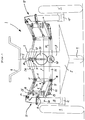
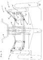
- FIG. 1 there is shown a three-wheeled amphibian having a two front one rear wheel configuration, the amphibian being indicated in general by reference 1.
- the amphibian 1 is provided with a hull section 2 and a body 3.
- Handlebars 4 are provided at an upper region of the amphibian 1 and are connected to a steering column 5 which transcends downwardly towards the ground upon which the amphibian 1 is resting.
- a pivotally mounted steering arm 6 is connected to the steering column 5 and has pivot points 7 and 8 for connection with a suspension assembly of the present invention.
- a rear wheel 9 is provided.
- the amphibian 1 includes a first suspension assembly 10, a corresponding second suspension assembly 10' and a wheel 11, 11' for each suspension assembly 10, 10', each wheel 11, 11' being mounted to a wheel hub mount 12, 12' of the suspension assembly 10, 10'.
- Both suspension assemblies 10, 10' are the same and, therefore, only suspension assembly 10 will be described in detail below. However, when referring to the second suspension assembly 10', the suffix prime will always be used for its like numbered components.
- the suspension assembly 10 is provided with a suspension upright 13 which is connected to upper and lower suspension arms 14, 15. The upper and lower suspension arms 14, 15 are separated at a first end by an upright arm 16.
- the upper suspension arm 14 includes a pivotal connection 17 and the lower suspension arm 15 includes a pivotal connection 18, which pivotal connections 17, 18 allow respective movement between the upper suspension arm 14, the lower suspension arm 15 and the upright arm 16, at each end of the upright arm 16.
- the upper suspension arm 14 is provided at a second end with a further pivotal connection 19 which connects the upper suspension arm with the suspension upright 13, allowing movement of the two parts 14, 13.
- the lower suspension arm 15 is provided at a second end with a second pivotal connection 20, which connects that suspension arm 15 with the suspension upright 13, allowing movement of the two parts 15, 13.
- a damper 21 is provided that is connected at a first lower end to one end of a lower control arm 22 through a pivotal connection 23.
- This damper is surrounded by a coil suspension spring (not shown).
- the control arm 22 is fixed to the lower suspension arm 15 at its other end.
- the second upper end of the damper 21 is connected to a first end of control arm 24 by a pivotal connection 25.
- the other end of control arm 24 is fixed to upright 16.
- upper suspension arm 14 is pivotally connected to upright 16 and therefore arm 24 through a pivotal connection 17.
- Each wheel suspension therefore acts as a double wishbone suspension due to having parallel arms 14 and 15, but the upper ends of the spring and damper 21 are constrained to compress on bump travel by the fixing of upper arm 24 to upright 16, so that upper arm 24 cannot rotate in bump and rebound.
- Pivotal connections 23 and 25 include rubber bushes (not shown) to allow some relative movements due to the geometric conflicts inherent in this design.
- the lower suspension arm 15 and the upright 16 are pivotally connected at pivotal connection 18 to a lower link arm 26, which is pivotally connected at 27 to the body 3 of the amphibian 1. Owing to pivotal connection 27, the suspension apparatus 10 is moveable with respect to the body of the amphibian 1, so as to allow the amphibian 1 to lean when cornering. Further, the upper suspension arm 14 and upright arm 16 are pivotally connected at 17 to a retraction ram 28, for moving the suspension apparatus 10 from its protracted land mode position to its retracted marine mode position. A second end of the retraction ram 28 is connected to a first end of a drop link 31 by a pivotal connection 29. The drop link 31 is in turn connected to the body 3 by a further pivotal connection 32 at a second end. The pivotal connection 32 connects the drop link 31 to the body 3 and allows the drop link 31 to rotate during cornering of the amphibian 1, and when displaced by the retraction rams 28, 28' when leaning.
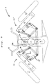
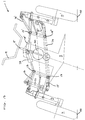
- FIG. 2 shows the amphibian 1 in its marine mode, with wheels retracted.
- Each of the suspension apparati 10, 10' have been retracted and are now raised above the hull section 2 of the amphibian 1.
- a motor and gearbox assembly 30 is attached to the body 3. Through the actions of pivotal connections 27, 29, and 32, assembly 30 allows or provides for controlled lean of the amphibian 1. In particular, such control of the amphibian 1 dictates the amount of lean when cornering and, for example, keeps the amphibian 1 upright when stationary.
- the motor may be an electrical, particularly a stepper motor, or a hydraulic or pneumatic motor, and is attached to the body 3.
- the gearbox assembly may lock pivots 27, 29, and 32, preventing undesired lean of the amphibian 1.
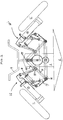
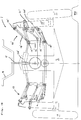
- Figure 3 shows the amphibian 1 when leaning during cornering.
- the amphibian 1 is moving forward out from the page, the amphibian is turning left in Figure 3 .
- All three wheels 11, 11', 9 alter their orientation with respect to the ground such that a more peripheral part 40 of each wheel 11, 11', 9 contacts the ground when cornering - in the same way that this occurs when cornering on a motorbike.
- the body 3' of Figure 3 is now leant over at the same angle as the suspension uprights 13, 13'.
- the suspension assembly 10 is on an outside of a corner and the suspension assembly 10' is on an inside of a corner.
- the link arm 26 has rotated around the pivotal connection 27 and the retraction rams 28, 28' have rotated around the pivotal connection 32 via drop link 31, to alter the orientation of the suspension assemblies 10, 10'.
- the suspension arms 14, 15 have rotated downwardly around the pivotal connections 17, 18 in order to allow the wheel 11 to stay on the ground.
- the spring and damper 21 have been extended and the relative position of the upper suspension arm 14 with respect to the damper 21 is lowered, as can be seen from comparing Figures 1 and 3 .
- suspension assembly 10 For suspension assembly 10 to be on an outside of a corner, the assembly must be able to place the wheel 11 in a relative lower position than the wheel 11 would be in, in an upright rest position of the amphibian 1. Further, on assembly 10', the suspension arms 14', 15' have rotated upwardly around the pivotal connections 17', 18' in order to allow the other wheel 11' to stay on the ground. In doing this, the spring and damper 21' have been shortened and the relative position of the upper suspension arm 14' with respect to the damper 21' is heightened, as can be seen from comparing Figures 1 and 3 . Therefore, it will be understood that for suspension assembly 10' to be on an inside of a corner, the assembly 10' must be able to place the wheel 11' in a relative higher position than the wheel 11' would be in, in an upright rest position of the amphibian 1.
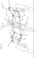
- FIG 4 Operation of the amphibian suspension in bump travel is shown in Figure 4 .
- the suspension assemblies 10, 10' are shown in their protracted, land-use positions.
- the suspension assembly 10 is shown traversing flat ground and the suspension assembly 10' is traversing a bump 50.
- both suspension arms 14', 15' are raised to accommodate the bump 50.
- the pivotal connections 17', 18', 19', 20' allow rotation of the suspension arms 14', 15' to substantially maintain the orientation of the wheel with respect to the ground.
- the spring and damper 21 has been compressed.
- FIG. 5 is a schematic partial-plan view from above of the amphibian 1, shown in a land mode with wheel and suspension assemblies protracted. This Figure illustrates the two front one rear wheel configuration, the amphibian 1 having two front wheels 11, 11' and a single rear wheel 9.
- a chassis frame 42 is provided, and a rear wheel retraction ram 49.
- Powered lean of the amphibian 1 can be provided by suitably controlling the pivotal connections 27 and/or 29.
- the motor and gearbox 30 may either provide resistance to rotation of the retraction rams 28, 28' and/or link arm 26, or may power rotation of those parts. Further, the retraction rams 28, 28' themselves can be used to alter the orientation of the wheels 11, 11', 9 when cornering.
- FIG. 6 there is shown a three-wheeled amphibian having a one front two rear wheel configuration, the amphibian being indicated in general by reference 1.
- the amphibian 1 is provided with a hull section 2 and a body 3.
- Handlebars 4 are provided at an upper region of the amphibian 1 and are connected to a steering column 5 which transcends downwardly towards the ground upon which the amphibian 1 is resting, and connecting with forks supporting the front wheel 9.
- a front wheel 9 and rear wheels 11, 11' are provided.
- the amphibian 1 includes a first suspension assembly 10, a corresponding second suspension assembly 10' and a wheel 11, 11' for each suspension assembly 10, 10', each wheel 11, 11' being mounted to a wheel hub mount 12, 12' of the suspension assembly 10, 10'.
- Both suspension assemblies 10, 10' are the same and, therefore, only suspension assembly 10 will be described in detail below. However, when referring to the second suspension assembly 10', the suffix prime will always be used for its like numbered components.
- The-suspension assembly 10 is provided with a suspension upright 13 which is connected to upper and lower suspension arms 14, 15. The upper and lower suspension arms 14, 15 are separated at a first end by an upright arm 16.
- the upper suspension arm 14 includes a pivotal connection 17 and the lower suspension arm 15 includes a pivotal connection 18, which pivotal connections 17, 18 allow respective movement between the upper suspension arm 14, the lower suspension arm 15 and the upright arm 16, at each end of the upright arm 16.
- the upper suspension arm 14 is provided at a second end with a further pivotal connection 19 which connects the upper suspension arm with the suspension upright 13, allowing movement of the two parts 14, 13.
- the lower suspension arm 15 is provided at a second end with a second pivotal connection 20, which connects that suspension arm 15 with the suspension upright 13, allowing movement of the two parts 15, 13.
- a damper 21 is provided that is connected at a first lower end to one end of a lower control arm 22 through a pivotal connection 23.
- This damper is surrounded by a coil suspension spring (not shown).
- the control arm 22 is fixed to the lower suspension arm 15 at its other end.
- the second upper end of the damper 21 is connected to a first end of control arm 24 by a pivotal connection 25.
- the other end of control arm 24 is fixed to upright 16.
- upper suspension arm 14 is pivotally connected to upright 16 and therefore arm 24 through a pivotal connection 17.
- Each wheel suspension therefore acts as a double wishbone suspension due to having parallel arms 14 and 15, but the upper ends of the spring and damper 21 are constrained to compress on bump travel by the fixing of upper arm 24 to upright 16, so that upper arm 24 cannot rotate in bump and rebound.
- Pivotal connections 23 and 25 include rubber bushes (not shown) to allow some relative movements due to the geometric conflicts inherent in this design.
- the lower suspension arm 15 and the upright 16 are pivotally connected at pivotal connection 18 to a lower link arm 26, which is pivotally connected at 27 to the body 3 of the amphibian 1. Owing to pivotal connection 27, the suspension apparatus 10 is moveable with respect to the body of the amphibian 1, so as to allow the amphibian 1 to lean when cornering. Further, the upper suspension arm 14 and upright arm 16 are pivotally connected at 17 to a retraction ram 28, for moving the suspension apparatus 10 from its protracted land mode position to its retracted marine mode position. A second end of the retraction ram 28 is connected to a first end of a drop link 31 by a pivotal connection 29. The drop link 31 is in turn connected to the body 3 by a further pivotal connection 32 at a second end. The pivotal connection 32 connects the drop link 31 to the body 3 and allows the drop link 31 to rotate during cornering of the amphibian 1, and when displaced by the retraction rams 28, 28' when leaning.
- FIG. 7 shows the amphibian 1 in its marine mode, with wheels retracted.
- Each of the suspension apparati 10, 10' have been retracted and are now raised above the hull section 2 of the amphibian 1.
- a motor and gearbox assembly 30 is attached to the body 3. Through the actions of pivotal connections 27, 29, and 32, assembly 30 allows or provides for controlled lean of the amphibian 1. In particular, such control of the amphibian 1 dictates the amount of lean when cornering and, for example, keeps the amphibian 1 upright when stationary.
- the motor may be an electrical, particularly a stepper motor, or a hydraulic or pneumatic motor, and is attached to the body 3.
- the gearbox assembly may lock pivots 27, 29, and 32, preventing undesired lean of the amphibian 1.
- Figure 8 shows the amphibian 1 when leaning during cornering.
- the amphibian 1 is moving forward out from the page, the amphibian is turning left in Figure 3 .
- All three wheels 11, 11', 9 alter their orientation with respect to the ground such that a more peripheral part 40 of each wheel 11, 11', 9 contacts the ground when cornering - in the same way that this occurs when cornering on a motorbike.
- the body 3' of Figure 3 is now leant over at the same angle as the suspension uprights 13, 13'.
- the suspension assembly 10 is on an outside of a corner and the suspension assembly 10' is on an inside of a corner.
- the link arm 26 has rotated around the pivotal connection 27 and the retraction rams 28, 28' have rotated around the pivotal connection 32 via drop link 31, to alter the orientation of the suspension assemblies 10, 10'.
- the suspension arms 14, 15 have rotated downwardly around the pivotal connections 17, 18 in order to allow the wheel 11 to stay on the ground.
- the spring and damper 21 have been extended and the relative position of the upper suspension arm 14 with respect to the damper 21 is lowered, as can be seen from comparing Figures 1 and 3 .
- suspension assembly 10 For suspension assembly 10 to be on an outside of a corner, the assembly must be able to place the wheel 11 in a relative lower position than the wheel 11 would be in, in an upright rest position of the amphibian 1. Further, on assembly 10', the suspension arms 14', 15' have rotated upwardly around the pivotal connections 17', 18' in order to allow the other wheel 11' to stay on the ground. In doing this, the spring and damper 21' have been shortened and the relative position of the upper suspension arm 14' with respect to the damper 21' is heightened, as can be seen from comparing Figures 1 and 3 . Therefore, it will be understood that for suspension assembly 10' to be on an inside of a corner, the assembly 10' must be able to place the wheel 11' in a relative higher position than the wheel 11' would be in, in an upright rest position of the amphibian 1.
- FIG. 9 Operation of the amphibian suspension in bump travel is shown in Figure 9 .
- the suspension assemblies 10, 10' are shown in their protracted, land-use positions.
- the suspension assembly 10 is shown traversing flat ground and the suspension assembly 10' is traversing a bump 50.
- both suspension arms 14', 15' are raised to accommodate the bump 50.
- the pivotal connections 17', 18', 19', 20' allow rotation of the suspension arms 14', 15' to substantially maintain the orientation of the wheel with respect to the ground.
- the spring and damper 21 has been compressed.
- Figure 10 is a schematic partial-plan view from above of the amphibian 1 of Figures 6 to 9 , shown in a land mode with wheel and suspension assemblies protracted.
- This Figure illustrates the one front two rear wheel configuration, the amphibian 1 having a single front wheel 9 and two rear wheels 11, 11'.
- a chassis frame 42 is provided, and a front wheel retraction ram (not shown) similar to the rear wheel retraction ram 49 shown in Figure 5 .
- Powered lean of the amphibian 1 can be provided by suitably controlling the pivotal connections 27 and/or 29.
- the motor and gearbox 30 may either provide resistance to rotation of the retraction rams 28, 28' and/or link arm 26, or may power rotation of those parts. Further, the retraction rams 28, 28' themselves can be used to alter the orientation of the wheels 11, 11', 9 when cornering.
- FIG. 11 to 15 there is shown a four-wheeled amphibian having a two front two rear wheel configuration, the amphibian being indicated in general by reference 1.
- the amphibian 1 is provided with a hull section 2 and a body 3.
- Handlebars 4 are provided at an upper region of the amphibian 1 and are connected to a steering column 5 which transcends downwardly towards the ground upon which the amphibian 1 is resting.
- a pivotally mounted steering arm 6 is connected to the steering column 5 and has pivot points 7 and 8 for connection with a suspension assembly of the present invention.
- Two rear wheels 9, 9' are provided.
- the amphibian 1 may have four-wheel steering and be provided with steering mechanisms at the front and rear.
- the amphibian 1 includes a first suspension assembly 10, a corresponding second suspension assembly-10' and a wheel 11, 11' for each suspension assembly 10, 10', each wheel 11, 11' being mounted to a wheel hub mount 12, 12' of the suspension assembly 10, 10'.
- the amphibian 1 includes third and fourth suspension assemblies 10" , 10"' and wheels 9, 9' for each suspension assembly 10" , 10"', each wheel 9, 9' being mounted to a wheel hub mount 12", 12"' of the suspension assembly 10", 10"'.
- Both suspension assemblies 10" , 10"' are substantially the same as suspension assemblies 10, 10' (differing only in terms of facing direction) and, therefore, only suspension assembly 10 will be described in detail below.
- the suspension assembly 10 is provided with a suspension upright 13 which is connected to upper and lower suspension arms 14, 15.
- the upper and lower suspension arms 14, 15 are separated at a first end by an upright arm 16.
- the upper suspension arm 14 includes a pivotal connection 17 and the lower suspension arm 15 includes a pivotal connection 18, which pivotal connections 17, 18 allow respective movement between the upper suspension arm 14, the lower suspension arm 15 and the upright arm 16, at each end of the upright arm 16.
- the upper suspension arm 14 is provided at a second end with a further pivotal connection 19 which connects the upper suspension arm with the suspension upright 13, allowing movement of the two parts 14, 13.
- the lower suspension arm 15 is provided at a second end with a second pivotal connection 20, which connects that suspension arm 15 with the suspension upright 13, allowing movement of the two parts 15, 13.
- a damper 21 is provided that is connected at a first lower end to one end of a lower control arm 22 through a pivotal connection 23.
- This damper is surrounded by a coil suspension spring (not shown).
- the control arm 22 is fixed to the lower suspension arm 15 at its other end.
- the second upper end of the damper 21 is connected to a first end of control arm 24 by a pivotal connection 25.
- the other end of control arm 24 is fixed to upright 16.
- upper suspension arm 14 is pivotally connected to upright 16 and therefore arm 24 through a pivotal connection 17.
- Each wheel suspension therefore acts as a double wishbone suspension due to having parallel arms 14 and 15, but the upper ends of the spring and damper 21 are constrained to compress on bump travel by the fixing of upper arm 24 to upright 16, so that upper arm 24 cannot rotate in bump and rebound.
- Pivotal connections 23 and 25 include rubber bushes (not shown) to allow some relative movements due to the geometric conflicts inherent in this design.
- the lower suspension arm 15 and the upright 16 are pivotally connected at pivotal connection 18 to a lower link arm 26, which is pivotally connected at 27 to the body 3 of the amphibian 1. Owing to pivotal connection 27, the suspension apparatus 10 is moveable with respect to the body of the amphibian 1, so as to allow the amphibian 1 to lean when cornering. Further, the upper suspension arm 14 and upright arm 16 are pivotally connected at 17 to a retraction ram 28, for moving the suspension apparatus 10 from its protracted land mode position to its retracted marine mode position. A second end of the retraction ram 28 is connected to a first end of a drop link 31 by a pivotal connection 29. The drop link 31 is in turn connected to the body 3 by a further pivotal connection 32 at a second end. The pivotal connection 32 connects the drop link 31 to the body 3 and allows the drop link 31 to rotate during cornering of the amphibian 1, and when displaced by the retraction rams 28, 28' when leaning.
- FIG 12 shows the amphibian 1 in its marine mode, with wheels retracted.
- Each of the suspension apparati 10, 10', 10" , 10"' have been retracted and are now raised above the hull section 2 of the amphibian 1.
- a motor and gearbox assembly 30 is attached to the body 3. Through the actions of pivotal connections 27, 29, and 32, assembly 30 allows or provides for controlled lean of the amphibian 1. In particular, such control of the amphibian 1 dictates the amount of lean when cornering and, for example, keeps the amphibian 1 upright when stationary.
- the motor may be an electrical, particularly a stepper motor, or a hydraulic or pneumatic motor, and is attached to the body 3.
- the gearbox assembly may lock pivots 27, 29, and 32, preventing undesired lean of the amphibian 1.
- Figure 13 shows the amphibian 1 when leaning during cornering.
- the amphibian 1 is moving forward out from the page, the amphibian is turning left in Figure 3 .
- All four wheels 11, 11', 9, 9' alter their orientation with respect to the ground such that a more peripheral part 40 of each wheel 11, 11', 9, 9' contacts the ground when cornering - in the same way that this occurs when cornering on a motorbike.
- the body 3' of Figure 3 is now leant over at the same angle as the suspension uprights 13, 13'.
- the suspension assemblies 10, 10" are on an outside of a corner and the suspension assemblies 10', 10"' are on an inside of a corner.
- the link arm 26 has rotated around the pivotal connection 27 and the retraction rams 28, 28' have rotated around the pivotal connection 32 via drop link 31, to alter the orientation of the suspension assemblies 10, 10', 10" , 10"'.
- the suspension arms 14, 15 have rotated downwardly around the pivotal connections 17, 18 in order to allow the wheel 11 to stay on the ground.
- the spring and damper 21 have been extended and the relative position of the upper suspension arm 14 with respect to the damper 21 is lowered, as can be seen from comparing Figures 1 and 3 .
- FIG 14 Operation of the amphibian suspension in bump and rebound is shown in Figure 14 .
- the suspension assemblies 10, 10', 10" , 10"' are shown in their protracted, land-use positions.
- the suspension assembly 10 is shown traversing flat ground and the suspension assembly 10' is traversing a bump 50.
- both suspension arms 14', 15' are raised to accommodate the bump 50.
- the pivotal connections 17', 18', 19', 20' allow rotation of the suspension arms 14', 15' to substantially maintain the orientation of the wheel with respect to the ground.
- the spring and damper 21 has been compressed.
- Figure 15 is a schematic partial-plan view from above of the amphibian 1 of Figures 11 to 14 , shown in a land mode with wheel and suspension assemblies protracted. This Figure illustrates the two front two rear wheel configuration, the amphibian 1 having two front wheels 11, 11' and two rear wheels 9, 9'.
- Powered lean of the amphibian 1 can be provided by suitably controlling the pivotal connections 27 and/or 29.
- the motor and gearbox 30 may either provide resistance to rotation of the retraction rams 28, 28' and/or link arm 26, or may power rotation of those parts. Further, the retraction rams 28, 28' themselves can be used to alter the orientation of the wheels 11, 11', 9, 9' when cornering.
- retractable leaning suspension assembly 10, 10', 10" , 10"' has been described in the context of an amphibian 1 where all three or four wheels lean, it may also be applied to a three-wheeled amphibian 1 whose single rear or front wheel does not lean, but rolls in corners as a car tyre does.
- a vee-type hull 2 is shown in the Figures, and this is generally chosen for a planing amphibian 1 to give agile handling in marine mode.
- this hull 2 form is advantageous for a leaning amphibian 1 on land, in that ground clearance is maintained as the amphibian 1 leans, up to a lean angle corresponding at least to the vee angle of the hull 2.
- the amphibian according to the present invention has been described herein as a three- or four-wheeled amphibian, this is to be taken as meaning that the amphibian has three or four wheel receiving stations, with at least one wheel provided at each wheel station. It is of course possible for a wheel provided at a wheel station to in fact comprise two or more thin wheels provided side by side.
Landscapes
- Engineering & Computer Science (AREA)
- Mechanical Engineering (AREA)
- Chemical & Material Sciences (AREA)
- Combustion & Propulsion (AREA)
- Transportation (AREA)
- Axle Suspensions And Sidecars For Cycles (AREA)
- Automatic Cycles, And Cycles In General (AREA)
- Vehicle Body Suspensions (AREA)
- Motorcycle And Bicycle Frame (AREA)
Applications Claiming Priority (2)
| Application Number | Priority Date | Filing Date | Title |
|---|---|---|---|
| GB0811335.9A GB2461081B (en) | 2008-06-19 | 2008-06-19 | A three-wheeled amphibian with retractable wheels |
| PCT/GB2009/001559 WO2009153578A1 (en) | 2008-06-19 | 2009-06-19 | Improvements in or relating to amphibians |
Publications (2)
| Publication Number | Publication Date |
|---|---|
| EP2310216A1 EP2310216A1 (en) | 2011-04-20 |
| EP2310216B1 true EP2310216B1 (en) | 2016-03-16 |
Family
ID=39682882
Family Applications (1)
| Application Number | Title | Priority Date | Filing Date |
|---|---|---|---|
| EP09766139.1A Not-in-force EP2310216B1 (en) | 2008-06-19 | 2009-06-19 | Improvements in or relating to amphibians |
Country Status (10)
| Country | Link |
|---|---|
| US (1) | US20110275256A1 (enExample) |
| EP (1) | EP2310216B1 (enExample) |
| JP (2) | JP2011524836A (enExample) |
| KR (1) | KR20110034642A (enExample) |
| CN (1) | CN102202921B (enExample) |
| AU (1) | AU2009261753A1 (enExample) |
| CA (1) | CA2728419C (enExample) |
| GB (1) | GB2461081B (enExample) |
| TW (1) | TW201008799A (enExample) |
| WO (1) | WO2009153578A1 (enExample) |
Families Citing this family (53)
| Publication number | Priority date | Publication date | Assignee | Title |
|---|---|---|---|---|
| WO2006032052A2 (en) | 2004-09-15 | 2006-03-23 | Yeti Cycling, Llc | Rear suspension system for a bicycle |
| WO2012024697A1 (en) * | 2010-08-20 | 2012-02-23 | Peter Zawistowski | Link suspension system |
| US9821879B2 (en) | 2010-08-20 | 2017-11-21 | Yeti Cycling, Llc | Reciprocating rail movement suspension system |
| GB2491845B (en) * | 2011-06-13 | 2013-08-21 | Gibbs Tech Ltd | A retractable wheel assembly for an amphibian |
| CN106143030B (zh) * | 2011-06-30 | 2018-11-16 | 凯勒·迪克 | 两栖船舶以及包括舷梯装置的船舶 |
| US20130193668A1 (en) * | 2012-01-20 | 2013-08-01 | Ronald Decker | Adult tricycle |
| US8794641B2 (en) * | 2012-04-12 | 2014-08-05 | Christopher Muller | Multi use recreational utility vehicle |
| AT513539B1 (de) * | 2012-10-16 | 2022-11-15 | Mario Eibl | Fahrzeug mit verstellbarer Radachse |
| CN104487324A (zh) * | 2012-10-25 | 2015-04-01 | 雅马哈发动机株式会社 | 车辆 |
| MX352173B (es) * | 2012-12-21 | 2017-11-13 | Yamaha Motor Co Ltd | Vehiculo. |
| US10766563B2 (en) | 2013-01-16 | 2020-09-08 | Yeti Cyclying, Llc | Rail suspension with integral shock and dampening mechanism |
| CN103192916B (zh) * | 2013-04-22 | 2015-09-16 | 昆明理工大学 | 一种转弯可侧倾倒三轮太阳能车车架 |
| US9061564B1 (en) * | 2013-12-18 | 2015-06-23 | Automotive Research & Testing Center | Active vehicle with a variable inclination apparatus and method of using the same |
| US9387902B2 (en) * | 2014-01-16 | 2016-07-12 | Scorpion Trikes, Inc. | Assembly for increasing motorcycle wheel count |
| CN104859765A (zh) * | 2014-02-22 | 2015-08-26 | 倪明旺 | 三轮摩托车变形桥架 |
| CN104443182B (zh) * | 2015-01-05 | 2018-01-02 | 太仓市车中宝休闲用品有限公司 | 可调节防侧翻式三轮漂移车 |
| GB2551683B (en) * | 2015-05-07 | 2019-01-30 | Gibbs Tech Ltd | A retractable wheel assembly for an amphibian |
| GB201509933D0 (en) * | 2015-06-08 | 2015-07-22 | Gibbs Tech Ltd | A power train for an amphibian |
| MA43333A (fr) * | 2015-07-29 | 2018-06-06 | Piaggio & C Spa | Suspension avant de véhicule à moteur |
| MA43334A (fr) * | 2015-07-29 | 2018-06-06 | Piaggio & C Spa | Suspension avant pour véhicule à moteur |
| ITUB20152766A1 (it) * | 2015-08-03 | 2017-02-03 | Piaggio & C Spa | Avantreno di motoveicolo tiltante e relativo motoveicolo |
| GB2543746B (en) * | 2015-10-15 | 2021-02-10 | Gibbs Tech Ltd | High speed actuation system, apparatus and method for protracting and retracting a retractable wheel assembly of an amphibian |
| CN105216565A (zh) * | 2015-10-23 | 2016-01-06 | 中国嘉陵工业股份有限公司(集团) | 一种两栖车车轮收放装置的收放机构 |
| CN105235458A (zh) * | 2015-10-23 | 2016-01-13 | 中国嘉陵工业股份有限公司(集团) | 一种两栖车车轮收放装置 |
| JP6648155B2 (ja) * | 2015-11-13 | 2020-02-14 | ヤマハ発動機株式会社 | 傾斜車両 |
| CA3005012A1 (en) * | 2015-11-13 | 2017-05-18 | Yamaha Hatsudoki Kabushiki Kaisha | Leaning vehicle |
| WO2017086405A1 (ja) * | 2015-11-20 | 2017-05-26 | ヤマハ発動機株式会社 | 車両 |
| JP6722916B2 (ja) * | 2016-03-31 | 2020-07-15 | 株式会社エクォス・リサーチ | 車両 |
| WO2017183639A1 (ja) * | 2016-04-18 | 2017-10-26 | ヤマハ発動機株式会社 | リーン車両 |
| US9834271B1 (en) * | 2016-06-01 | 2017-12-05 | Michael Hsing | Vehicle with leaning suspension system |
| IT201600071697A1 (it) * | 2016-07-08 | 2018-01-08 | Piaggio & C Spa | Avantreno di motoveicolo tiltante e relativo motoveicolo |
| WO2018043408A1 (ja) * | 2016-08-29 | 2018-03-08 | 国立大学法人 東京大学 | 車両 |
| CN106335601B (zh) * | 2016-08-29 | 2018-03-16 | 南通中远川崎船舶工程有限公司 | 一种基于采集并分析大数据的船舶节能方法 |
| JP2018144698A (ja) * | 2017-03-07 | 2018-09-20 | ヤマハ発動機株式会社 | 車両 |
| JP2018144697A (ja) * | 2017-03-07 | 2018-09-20 | ヤマハ発動機株式会社 | 車両 |
| WO2018170505A1 (en) | 2017-03-17 | 2018-09-20 | Yeti Cycling, Llc | Vehicle suspension linkage |
| CN107116980B (zh) * | 2017-06-27 | 2023-02-03 | 西南科技大学 | 水陆两栖机器人以及水陆两栖侦查系统 |
| EP3649040A4 (en) | 2017-07-07 | 2021-03-10 | Yeti Cycling, LLC | VEHICLE SUSPENSION JOINT |
| EP3728007B1 (en) * | 2017-12-22 | 2021-10-06 | Piaggio & C. S.P.A. | A tilting motor cycle with three wheels and a rigid rear axle |
| WO2019172496A1 (ko) * | 2018-03-06 | 2019-09-12 | 유제우 | 틸팅카 프레임 |
| CN108725624B (zh) * | 2018-05-28 | 2023-06-20 | 佛山科学技术学院 | 一种多足机械人的多步态行走装置及其行走方法 |
| CN108944295A (zh) * | 2018-05-29 | 2018-12-07 | 中国北方车辆研究所 | 一种用于水陆两用车辆的车轮 |
| CN109353405B (zh) * | 2018-08-29 | 2021-08-03 | 河南坐骑科技有限公司 | 车辆转向侧倾联动机构及侧倾控制方法 |
| CN109318669A (zh) * | 2018-10-22 | 2019-02-12 | 李新 | 一种新型水陆两用沙滩车 |
| US12077241B2 (en) | 2019-02-01 | 2024-09-03 | Yeti Cycling, Llc | Multi-body vehicle suspension linkage |
| WO2021118381A1 (ru) * | 2019-12-09 | 2021-06-17 | Алексей Александрович КАЗАРЦЕВ | Переднеприводной трицикл с наклоняющей подвеской двух задних колес |
| US12145684B2 (en) | 2019-12-24 | 2024-11-19 | Yeti Cycling, Llc | Constrained multiple instantaneous velocity center linkage assembly for vehicle suspension |
| CN110979035A (zh) * | 2019-12-28 | 2020-04-10 | 芜湖安普机器人产业技术研究院有限公司 | 一种可在水泥回转窑变径弧面行走的小车 |
| GB2592406B (en) * | 2020-02-27 | 2023-08-09 | Dyson Technology Ltd | Robotic vehicle |
| CN111942096B (zh) * | 2020-08-04 | 2022-02-01 | 芜湖造船厂有限公司 | 一种水陆两栖车用的悬架提升系统及其使用方法 |
| US12384484B2 (en) | 2020-11-18 | 2025-08-12 | Yeti Cycling, Llc | Integrated motor mount and suspension pivot |
| IT202100012131A1 (it) * | 2021-05-12 | 2022-11-12 | Piaggio & C Spa | Un motoveicolo tiltante a sella con due ruote anteriori sterzanti rollanti e due ruote posteriori motrici non rollanti |
| CN117516638B (zh) * | 2024-01-08 | 2024-03-12 | 中交二公局东萌工程有限公司 | 一种隧道工程环境检测设备 |
Family Cites Families (28)
| Publication number | Priority date | Publication date | Assignee | Title |
|---|---|---|---|---|
| JPS583872B2 (ja) * | 1977-02-23 | 1983-01-24 | ウオルフガング・トロ−トウエイン | オ−トバイ |
| JPS5425033A (en) * | 1977-07-27 | 1979-02-24 | Yamaha Motor Co Ltd | Autobicycle |
| JPH06455B2 (ja) * | 1985-04-05 | 1994-01-05 | 本田技研工業株式会社 | 車体傾動装置 |
| GB8810479D0 (en) * | 1988-05-04 | 1988-06-08 | Royle D A C | Amphibious craft |
| US5690046A (en) * | 1995-11-21 | 1997-11-25 | Grzech, Jr.; Albert S. | Amphibious vehicles |
| WO1999061304A1 (en) * | 1998-05-28 | 1999-12-02 | Avantec Corporation | Tricycle |
| IT1317529B1 (it) * | 2000-05-16 | 2003-07-09 | Piaggio & C Spa | Veicolo a tre ruote con due ruote anteriori sterzanti |
| GB0029298D0 (en) * | 2000-12-01 | 2001-01-17 | Gibbs Int Tech Ltd | Suspension arrangement |
| AU2003206529A1 (en) * | 2002-02-22 | 2003-09-09 | Bombardier Recreational Products Inc. | Components for a three-wheeled vehicle to permit leaning of the driver |
| GB0311439D0 (en) * | 2003-05-19 | 2003-06-25 | Gibbs Tech Ltd | Amphibious vehicle |
| ITMI20031108A1 (it) * | 2003-06-03 | 2004-12-04 | Piaggio & C Spa | Veicolo rollante a tre ruote con due ruote anteriori sterzanti |
| JP2005104445A (ja) * | 2003-09-30 | 2005-04-21 | Honda Motor Co Ltd | 揺動車両 |
| ITMI20040171A1 (it) * | 2004-02-04 | 2004-05-04 | Piaggio & C Spa | Dispositivo anti-rollio per veicoli |
| GB2419332A (en) * | 2004-10-22 | 2006-04-26 | Gibbs Tech Ltd | Steering arrangement with retractable wheels |
| US20060199449A1 (en) * | 2004-10-22 | 2006-09-07 | Longdill Simon J | Amphibious vehicle |
| GB0423463D0 (en) * | 2004-10-22 | 2004-11-24 | Gibbs Tech Ltd | Amphibious vehicle suspension |
| CA2583365A1 (en) * | 2004-10-22 | 2006-04-27 | Gibbs Technologies Ltd. | Amphibious vehicle suspension |
| GB2419326A (en) * | 2004-10-22 | 2006-04-26 | Gibbs Tech Ltd | Amphibious vehicles with retractable wheels |
| DE102006022134A1 (de) * | 2005-05-13 | 2006-11-30 | Harley-Davidson Motor Company Group, Inc., Milwaukee | Selbstzentrierender Rückführmechanismus |
| US7571787B2 (en) * | 2005-09-30 | 2009-08-11 | Harley-Davidson Motor Company Group, LLC | Headlight mounting arrangement |
| JP4534944B2 (ja) * | 2005-10-07 | 2010-09-01 | トヨタ自動車株式会社 | 乗り物 |
| WO2007127783A1 (en) * | 2006-04-26 | 2007-11-08 | Vectrix Corporation | Vehicle with lockable tilt system |
| EP1884457B1 (en) * | 2006-07-26 | 2009-09-23 | Yamaha Motor Europe N.V. | Motorcycle |
| GB2441518A (en) * | 2006-08-24 | 2008-03-12 | Gibbs Tech Ltd | An amphibian vehicle having two front wheels and a single rear wheel |
| GB2445552B (en) * | 2007-01-15 | 2009-05-13 | Gibbs Tech Ltd | Wheel suspension and retraction apparatus |
| GB2452092B (en) * | 2007-08-24 | 2010-06-23 | Gibbs Tech Ltd | Improvements in or relating to amphibians |
| JP2010132185A (ja) * | 2008-12-05 | 2010-06-17 | Yamaha Motor Co Ltd | 雪上車 |
| PL3066001T3 (pl) * | 2013-11-08 | 2020-10-05 | Butchers & Bicycles Aps | Trójkołowy rower przechylny |
-
2008
- 2008-06-19 GB GB0811335.9A patent/GB2461081B/en not_active Expired - Fee Related
-
2009
- 2009-06-19 CA CA2728419A patent/CA2728419C/en not_active Expired - Fee Related
- 2009-06-19 JP JP2011514124A patent/JP2011524836A/ja active Pending
- 2009-06-19 AU AU2009261753A patent/AU2009261753A1/en not_active Abandoned
- 2009-06-19 KR KR1020117001452A patent/KR20110034642A/ko not_active Withdrawn
- 2009-06-19 CN CN200980131764.1A patent/CN102202921B/zh not_active Expired - Fee Related
- 2009-06-19 WO PCT/GB2009/001559 patent/WO2009153578A1/en not_active Ceased
- 2009-06-19 TW TW098120608A patent/TW201008799A/zh unknown
- 2009-06-19 EP EP09766139.1A patent/EP2310216B1/en not_active Not-in-force
- 2009-06-19 US US12/999,997 patent/US20110275256A1/en not_active Abandoned
-
2015
- 2015-04-02 JP JP2015075802A patent/JP2015155300A/ja active Pending
Also Published As
| Publication number | Publication date |
|---|---|
| CN102202921B (zh) | 2016-07-13 |
| JP2015155300A (ja) | 2015-08-27 |
| TW201008799A (en) | 2010-03-01 |
| GB2461081A (en) | 2009-12-23 |
| CN102202921A (zh) | 2011-09-28 |
| GB2461081B (en) | 2011-12-28 |
| JP2011524836A (ja) | 2011-09-08 |
| AU2009261753A1 (en) | 2009-12-23 |
| WO2009153578A1 (en) | 2009-12-23 |
| CA2728419C (en) | 2016-12-20 |
| EP2310216A1 (en) | 2011-04-20 |
| KR20110034642A (ko) | 2011-04-05 |
| CA2728419A1 (en) | 2009-12-23 |
| GB0811335D0 (en) | 2008-07-30 |
| US20110275256A1 (en) | 2011-11-10 |
Similar Documents
| Publication | Publication Date | Title |
|---|---|---|
| EP2310216B1 (en) | Improvements in or relating to amphibians | |
| US7909340B2 (en) | Vehicle with improved integrated steering and suspension system | |
| CN102470909B (zh) | 用于倾斜车辆的控制系统 | |
| US7708291B1 (en) | Vehicle with improved steering system | |
| EP2729351B1 (en) | A vehicle | |
| US9381785B2 (en) | Tilting vehicle and a method of tilting a vehicle with rear wheel supports having hydraulic cylinders communicating through a pump | |
| US8746721B2 (en) | Motorcycle steering with four-bar linkage | |
| JP2011524836A5 (enExample) | ||
| US20090289437A1 (en) | Vehicle with three wheels | |
| CN106573517B (zh) | 机动车 | |
| CA2780315A1 (en) | Leaning vehicle with tilting front wheels and suspension therefor | |
| JP2009509857A (ja) | 傾斜サスペンションマシン | |
| USRE44854E1 (en) | Vehicle with improved integrated steering and suspension system | |
| US12371120B2 (en) | Vehicle with a stability system that compensates for the centrifugal force and the transverse component of the inertia force when cornering | |
| CN104271434A (zh) | 具有姿势控制功能的车辆 | |
| EP1894753B1 (en) | Structure for enabling independently suspended wheels to lean with vehicle hull | |
| JP2006264510A (ja) | 自動車 | |
| CN113056415B (zh) | 用于具有两个前转向轮的机动车的具有中央减震器组件的前轮架及包括该前轮架的机动车 | |
| JP6737963B2 (ja) | 自動二輪車 | |
| US20140049021A1 (en) | Road holding ability mechanism for the two front wheels of a motorcycle | |
| US7819216B1 (en) | Motorcycle conversion assembly | |
| JP6694117B2 (ja) | 自動二輪車 |
Legal Events
| Date | Code | Title | Description |
|---|---|---|---|
| PUAI | Public reference made under article 153(3) epc to a published international application that has entered the european phase |
Free format text: ORIGINAL CODE: 0009012 |
|
| 17P | Request for examination filed |
Effective date: 20110114 |
|
| AK | Designated contracting states |
Kind code of ref document: A1 Designated state(s): AT BE BG CH CY CZ DE DK EE ES FI FR GB GR HR HU IE IS IT LI LT LU LV MC MK MT NL NO PL PT RO SE SI SK TR |
|
| AX | Request for extension of the european patent |
Extension state: AL BA RS |
|
| DAX | Request for extension of the european patent (deleted) | ||
| 17Q | First examination report despatched |
Effective date: 20130130 |
|
| RIC1 | Information provided on ipc code assigned before grant |
Ipc: B62K 5/10 20130101ALI20150326BHEP Ipc: B62K 5/027 20130101ALI20150326BHEP Ipc: B60F 3/00 20060101AFI20150326BHEP Ipc: B62K 5/00 20130101ALI20150326BHEP Ipc: B62K 13/00 20060101ALI20150326BHEP Ipc: B62K 5/05 20130101ALI20150326BHEP Ipc: B60G 3/18 20060101ALI20150326BHEP Ipc: B60G 21/00 20060101ALI20150326BHEP |
|
| GRAP | Despatch of communication of intention to grant a patent |
Free format text: ORIGINAL CODE: EPIDOSNIGR1 |
|
| INTG | Intention to grant announced |
Effective date: 20150512 |
|
| GRAS | Grant fee paid |
Free format text: ORIGINAL CODE: EPIDOSNIGR3 |
|
| GRAA | (expected) grant |
Free format text: ORIGINAL CODE: 0009210 |
|
| AK | Designated contracting states |
Kind code of ref document: B1 Designated state(s): AT BE BG CH CY CZ DE DK EE ES FI FR GB GR HR HU IE IS IT LI LT LU LV MC MK MT NL NO PL PT RO SE SI SK TR |
|
| REG | Reference to a national code |
Ref country code: GB Ref legal event code: FG4D |
|
| REG | Reference to a national code |
Ref country code: CH Ref legal event code: EP |
|
| REG | Reference to a national code |
Ref country code: IE Ref legal event code: FG4D |
|
| REG | Reference to a national code |
Ref country code: AT Ref legal event code: REF Ref document number: 780877 Country of ref document: AT Kind code of ref document: T Effective date: 20160415 |
|
| REG | Reference to a national code |
Ref country code: DE Ref legal event code: R096 Ref document number: 602009036831 Country of ref document: DE |
|
| REG | Reference to a national code |
Ref country code: FR Ref legal event code: PLFP Year of fee payment: 8 |
|
| REG | Reference to a national code |
Ref country code: NL Ref legal event code: MP Effective date: 20160316 |
|
| REG | Reference to a national code |
Ref country code: LT Ref legal event code: MG4D |
|
| PG25 | Lapsed in a contracting state [announced via postgrant information from national office to epo] |
Ref country code: FI Free format text: LAPSE BECAUSE OF FAILURE TO SUBMIT A TRANSLATION OF THE DESCRIPTION OR TO PAY THE FEE WITHIN THE PRESCRIBED TIME-LIMIT Effective date: 20160316 Ref country code: NO Free format text: LAPSE BECAUSE OF FAILURE TO SUBMIT A TRANSLATION OF THE DESCRIPTION OR TO PAY THE FEE WITHIN THE PRESCRIBED TIME-LIMIT Effective date: 20160616 Ref country code: HR Free format text: LAPSE BECAUSE OF FAILURE TO SUBMIT A TRANSLATION OF THE DESCRIPTION OR TO PAY THE FEE WITHIN THE PRESCRIBED TIME-LIMIT Effective date: 20160316 Ref country code: GR Free format text: LAPSE BECAUSE OF FAILURE TO SUBMIT A TRANSLATION OF THE DESCRIPTION OR TO PAY THE FEE WITHIN THE PRESCRIBED TIME-LIMIT Effective date: 20160617 |
|
| REG | Reference to a national code |
Ref country code: AT Ref legal event code: MK05 Ref document number: 780877 Country of ref document: AT Kind code of ref document: T Effective date: 20160316 |
|
| PG25 | Lapsed in a contracting state [announced via postgrant information from national office to epo] |
Ref country code: LT Free format text: LAPSE BECAUSE OF FAILURE TO SUBMIT A TRANSLATION OF THE DESCRIPTION OR TO PAY THE FEE WITHIN THE PRESCRIBED TIME-LIMIT Effective date: 20160316 Ref country code: LV Free format text: LAPSE BECAUSE OF FAILURE TO SUBMIT A TRANSLATION OF THE DESCRIPTION OR TO PAY THE FEE WITHIN THE PRESCRIBED TIME-LIMIT Effective date: 20160316 Ref country code: NL Free format text: LAPSE BECAUSE OF FAILURE TO SUBMIT A TRANSLATION OF THE DESCRIPTION OR TO PAY THE FEE WITHIN THE PRESCRIBED TIME-LIMIT Effective date: 20160316 Ref country code: SE Free format text: LAPSE BECAUSE OF FAILURE TO SUBMIT A TRANSLATION OF THE DESCRIPTION OR TO PAY THE FEE WITHIN THE PRESCRIBED TIME-LIMIT Effective date: 20160316 |
|
| PG25 | Lapsed in a contracting state [announced via postgrant information from national office to epo] |
Ref country code: EE Free format text: LAPSE BECAUSE OF FAILURE TO SUBMIT A TRANSLATION OF THE DESCRIPTION OR TO PAY THE FEE WITHIN THE PRESCRIBED TIME-LIMIT Effective date: 20160316 Ref country code: IS Free format text: LAPSE BECAUSE OF FAILURE TO SUBMIT A TRANSLATION OF THE DESCRIPTION OR TO PAY THE FEE WITHIN THE PRESCRIBED TIME-LIMIT Effective date: 20160716 Ref country code: PL Free format text: LAPSE BECAUSE OF FAILURE TO SUBMIT A TRANSLATION OF THE DESCRIPTION OR TO PAY THE FEE WITHIN THE PRESCRIBED TIME-LIMIT Effective date: 20160316 |
|
| PG25 | Lapsed in a contracting state [announced via postgrant information from national office to epo] |
Ref country code: SK Free format text: LAPSE BECAUSE OF FAILURE TO SUBMIT A TRANSLATION OF THE DESCRIPTION OR TO PAY THE FEE WITHIN THE PRESCRIBED TIME-LIMIT Effective date: 20160316 Ref country code: AT Free format text: LAPSE BECAUSE OF FAILURE TO SUBMIT A TRANSLATION OF THE DESCRIPTION OR TO PAY THE FEE WITHIN THE PRESCRIBED TIME-LIMIT Effective date: 20160316 Ref country code: CZ Free format text: LAPSE BECAUSE OF FAILURE TO SUBMIT A TRANSLATION OF THE DESCRIPTION OR TO PAY THE FEE WITHIN THE PRESCRIBED TIME-LIMIT Effective date: 20160316 Ref country code: RO Free format text: LAPSE BECAUSE OF FAILURE TO SUBMIT A TRANSLATION OF THE DESCRIPTION OR TO PAY THE FEE WITHIN THE PRESCRIBED TIME-LIMIT Effective date: 20160316 Ref country code: PT Free format text: LAPSE BECAUSE OF FAILURE TO SUBMIT A TRANSLATION OF THE DESCRIPTION OR TO PAY THE FEE WITHIN THE PRESCRIBED TIME-LIMIT Effective date: 20160718 Ref country code: ES Free format text: LAPSE BECAUSE OF FAILURE TO SUBMIT A TRANSLATION OF THE DESCRIPTION OR TO PAY THE FEE WITHIN THE PRESCRIBED TIME-LIMIT Effective date: 20160316 |
|
| REG | Reference to a national code |
Ref country code: DE Ref legal event code: R097 Ref document number: 602009036831 Country of ref document: DE |
|
| PG25 | Lapsed in a contracting state [announced via postgrant information from national office to epo] |
Ref country code: BE Free format text: LAPSE BECAUSE OF FAILURE TO SUBMIT A TRANSLATION OF THE DESCRIPTION OR TO PAY THE FEE WITHIN THE PRESCRIBED TIME-LIMIT Effective date: 20160316 Ref country code: IT Free format text: LAPSE BECAUSE OF FAILURE TO SUBMIT A TRANSLATION OF THE DESCRIPTION OR TO PAY THE FEE WITHIN THE PRESCRIBED TIME-LIMIT Effective date: 20160316 |
|
| PLBE | No opposition filed within time limit |
Free format text: ORIGINAL CODE: 0009261 |
|
| STAA | Information on the status of an ep patent application or granted ep patent |
Free format text: STATUS: NO OPPOSITION FILED WITHIN TIME LIMIT |
|
| PG25 | Lapsed in a contracting state [announced via postgrant information from national office to epo] |
Ref country code: DK Free format text: LAPSE BECAUSE OF FAILURE TO SUBMIT A TRANSLATION OF THE DESCRIPTION OR TO PAY THE FEE WITHIN THE PRESCRIBED TIME-LIMIT Effective date: 20160316 Ref country code: MC Free format text: LAPSE BECAUSE OF FAILURE TO SUBMIT A TRANSLATION OF THE DESCRIPTION OR TO PAY THE FEE WITHIN THE PRESCRIBED TIME-LIMIT Effective date: 20160316 |
|
| REG | Reference to a national code |
Ref country code: CH Ref legal event code: PL |
|
| 26N | No opposition filed |
Effective date: 20161219 |
|
| PG25 | Lapsed in a contracting state [announced via postgrant information from national office to epo] |
Ref country code: BG Free format text: LAPSE BECAUSE OF FAILURE TO SUBMIT A TRANSLATION OF THE DESCRIPTION OR TO PAY THE FEE WITHIN THE PRESCRIBED TIME-LIMIT Effective date: 20160616 |
|
| REG | Reference to a national code |
Ref country code: IE Ref legal event code: MM4A |
|
| PG25 | Lapsed in a contracting state [announced via postgrant information from national office to epo] |
Ref country code: CH Free format text: LAPSE BECAUSE OF NON-PAYMENT OF DUE FEES Effective date: 20160630 Ref country code: LI Free format text: LAPSE BECAUSE OF NON-PAYMENT OF DUE FEES Effective date: 20160630 |
|
| PG25 | Lapsed in a contracting state [announced via postgrant information from national office to epo] |
Ref country code: SI Free format text: LAPSE BECAUSE OF FAILURE TO SUBMIT A TRANSLATION OF THE DESCRIPTION OR TO PAY THE FEE WITHIN THE PRESCRIBED TIME-LIMIT Effective date: 20160316 Ref country code: IE Free format text: LAPSE BECAUSE OF NON-PAYMENT OF DUE FEES Effective date: 20160619 |
|
| REG | Reference to a national code |
Ref country code: FR Ref legal event code: PLFP Year of fee payment: 9 |
|
| PGFP | Annual fee paid to national office [announced via postgrant information from national office to epo] |
Ref country code: GB Payment date: 20170626 Year of fee payment: 9 Ref country code: FR Payment date: 20170616 Year of fee payment: 9 Ref country code: DE Payment date: 20170620 Year of fee payment: 9 |
|
| PG25 | Lapsed in a contracting state [announced via postgrant information from national office to epo] |
Ref country code: HU Free format text: LAPSE BECAUSE OF FAILURE TO SUBMIT A TRANSLATION OF THE DESCRIPTION OR TO PAY THE FEE WITHIN THE PRESCRIBED TIME-LIMIT; INVALID AB INITIO Effective date: 20090619 Ref country code: CY Free format text: LAPSE BECAUSE OF FAILURE TO SUBMIT A TRANSLATION OF THE DESCRIPTION OR TO PAY THE FEE WITHIN THE PRESCRIBED TIME-LIMIT Effective date: 20160316 |
|
| PG25 | Lapsed in a contracting state [announced via postgrant information from national office to epo] |
Ref country code: TR Free format text: LAPSE BECAUSE OF FAILURE TO SUBMIT A TRANSLATION OF THE DESCRIPTION OR TO PAY THE FEE WITHIN THE PRESCRIBED TIME-LIMIT Effective date: 20160316 Ref country code: LU Free format text: LAPSE BECAUSE OF NON-PAYMENT OF DUE FEES Effective date: 20160619 Ref country code: MT Free format text: LAPSE BECAUSE OF NON-PAYMENT OF DUE FEES Effective date: 20160630 Ref country code: MK Free format text: LAPSE BECAUSE OF FAILURE TO SUBMIT A TRANSLATION OF THE DESCRIPTION OR TO PAY THE FEE WITHIN THE PRESCRIBED TIME-LIMIT Effective date: 20160316 |
|
| REG | Reference to a national code |
Ref country code: DE Ref legal event code: R119 Ref document number: 602009036831 Country of ref document: DE |
|
| GBPC | Gb: european patent ceased through non-payment of renewal fee |
Effective date: 20180619 |
|
| PG25 | Lapsed in a contracting state [announced via postgrant information from national office to epo] |
Ref country code: DE Free format text: LAPSE BECAUSE OF NON-PAYMENT OF DUE FEES Effective date: 20190101 Ref country code: FR Free format text: LAPSE BECAUSE OF NON-PAYMENT OF DUE FEES Effective date: 20180630 Ref country code: GB Free format text: LAPSE BECAUSE OF NON-PAYMENT OF DUE FEES Effective date: 20180619 |