EP2307629B1 - Trennwand aus transparenten wandelementen - Google Patents
Trennwand aus transparenten wandelementen Download PDFInfo
- Publication number
- EP2307629B1 EP2307629B1 EP09761402.8A EP09761402A EP2307629B1 EP 2307629 B1 EP2307629 B1 EP 2307629B1 EP 09761402 A EP09761402 A EP 09761402A EP 2307629 B1 EP2307629 B1 EP 2307629B1
- Authority
- EP
- European Patent Office
- Prior art keywords
- elements
- pane
- profile frame
- wall
- wall according
- Prior art date
- Legal status (The legal status is an assumption and is not a legal conclusion. Google has not performed a legal analysis and makes no representation as to the accuracy of the status listed.)
- Active
Links
- 238000005192 partition Methods 0.000 title description 24
- 238000009413 insulation Methods 0.000 claims description 29
- 238000007789 sealing Methods 0.000 claims description 28
- 239000011521 glass Substances 0.000 claims description 23
- 238000000638 solvent extraction Methods 0.000 claims 14
- 230000000717 retained effect Effects 0.000 claims 1
- 239000000463 material Substances 0.000 description 4
- 230000000694 effects Effects 0.000 description 3
- XAGFODPZIPBFFR-UHFFFAOYSA-N aluminium Chemical compound [Al] XAGFODPZIPBFFR-UHFFFAOYSA-N 0.000 description 2
- 229910052782 aluminium Inorganic materials 0.000 description 2
- 230000010354 integration Effects 0.000 description 2
- 239000004033 plastic Substances 0.000 description 2
- 238000000926 separation method Methods 0.000 description 2
- 235000003332 Ilex aquifolium Nutrition 0.000 description 1
- 241000209027 Ilex aquifolium Species 0.000 description 1
- 229910000831 Steel Inorganic materials 0.000 description 1
- 230000004888 barrier function Effects 0.000 description 1
- 230000015572 biosynthetic process Effects 0.000 description 1
- 239000000356 contaminant Substances 0.000 description 1
- 230000001419 dependent effect Effects 0.000 description 1
- 238000011161 development Methods 0.000 description 1
- 230000018109 developmental process Effects 0.000 description 1
- 239000013013 elastic material Substances 0.000 description 1
- 238000009429 electrical wiring Methods 0.000 description 1
- 239000002985 plastic film Substances 0.000 description 1
- 230000010287 polarization Effects 0.000 description 1
- 239000007787 solid Substances 0.000 description 1
- 239000010959 steel Substances 0.000 description 1
- 239000002023 wood Substances 0.000 description 1
Images

Classifications
-
- E—FIXED CONSTRUCTIONS
- E04—BUILDING
- E04B—GENERAL BUILDING CONSTRUCTIONS; WALLS, e.g. PARTITIONS; ROOFS; FLOORS; CEILINGS; INSULATION OR OTHER PROTECTION OF BUILDINGS
- E04B2/00—Walls, e.g. partitions, for buildings; Wall construction with regard to insulation; Connections specially adapted to walls
- E04B2/74—Removable non-load-bearing partitions; Partitions with a free upper edge
- E04B2/82—Removable non-load-bearing partitions; Partitions with a free upper edge characterised by the manner in which edges are connected to the building; Means therefor; Special details of easily-removable partitions as far as related to the connection with other parts of the building
- E04B2/827—Partitions constituted of sliding panels
-
- E—FIXED CONSTRUCTIONS
- E06—DOORS, WINDOWS, SHUTTERS, OR ROLLER BLINDS IN GENERAL; LADDERS
- E06B—FIXED OR MOVABLE CLOSURES FOR OPENINGS IN BUILDINGS, VEHICLES, FENCES OR LIKE ENCLOSURES IN GENERAL, e.g. DOORS, WINDOWS, BLINDS, GATES
- E06B3/00—Window sashes, door leaves, or like elements for closing wall or like openings; Layout of fixed or moving closures, e.g. windows in wall or like openings; Features of rigidly-mounted outer frames relating to the mounting of wing frames
- E06B3/02—Wings made completely of glass
- E06B3/025—Wings made completely of glass consisting of multiple glazing units
-
- E—FIXED CONSTRUCTIONS
- E06—DOORS, WINDOWS, SHUTTERS, OR ROLLER BLINDS IN GENERAL; LADDERS
- E06B—FIXED OR MOVABLE CLOSURES FOR OPENINGS IN BUILDINGS, VEHICLES, FENCES OR LIKE ENCLOSURES IN GENERAL, e.g. DOORS, WINDOWS, BLINDS, GATES
- E06B3/00—Window sashes, door leaves, or like elements for closing wall or like openings; Layout of fixed or moving closures, e.g. windows in wall or like openings; Features of rigidly-mounted outer frames relating to the mounting of wing frames
- E06B3/32—Arrangements of wings characterised by the manner of movement; Arrangements of movable wings in openings; Features of wings or frames relating solely to the manner of movement of the wing
- E06B3/34—Arrangements of wings characterised by the manner of movement; Arrangements of movable wings in openings; Features of wings or frames relating solely to the manner of movement of the wing with only one kind of movement
- E06B3/42—Sliding wings; Details of frames with respect to guiding
- E06B3/46—Horizontally-sliding wings
- E06B3/4609—Horizontally-sliding wings for windows
Definitions
- the present invention relates to a partition with a plurality of wall elements, which are movably received via a guide means.
- the lateral planar surfaces of the wall elements are formed by transparent disc elements to provide a transparent mobile partition of several wall elements.
- Such wall elements for forming a mobile partition with transparent pane elements are used in rooms such as shops to form a mobile window front, in shops for variable separation of customer areas, in public buildings and in particular in banks, in which after closing an inner part of the customer area of an outer Part is separated.
- the transparent disc elements have fittings on which guide means are mounted to receive the wall elements, for example in a ceiling rail system and to lead in this. Often, the disc elements are arranged individually and form the body of the wall element itself. The fittings are then placed on the top and bottom of the disc element so that when several wall elements are juxtaposed to form the dividing wall, the disc elements are made of glass directly adjoin one another.
- partitions with a plurality of glass elements which are constructed of transparent disc elements, have the disadvantage that no sound insulation is possible because the disc elements on the one hand only simple and not double-walled and on the other hand have no seal in the edge region of the disc elements.
- wall elements are known for the formation of partitions which have sound insulation means, but such devices are not known for wall elements consisting of transparent disk elements. The problem already arises from the integration of a sound insulation device in the fittings, which border the disk element at least on the upper side and on the lower side.
- partitions with a plurality of wall elements are known, wherein the wall elements have a frame structure, are used in the tailored panels, which consist of MDF panels, solid wood panels or plastic sheets.
- Such wall elements have sound insulation means to provide a soundproof mobile partition.
- Wall elements are also known with windows, which are introduced in the form of a cutout within the side plates in this. The window section inside the side plates does not interfere with the integration of the sound insulation device, which usually takes up a considerable amount of space and is based on a spindle system, are moved by the sealing elements both against the ground and against the ceiling of the room.
- the DE 29822256 U1 shows a mobile glass partition wall according to the preamble of claim 1, in which a largely automatic extension of the sealing strips is made possible via pneumatic actuated lifting elements when the sliding elements move together.
- This glass partition can not achieve the required sound levels, since the glass sheets are arranged in a too small distance in the profile.
- the partition according to the invention has a plurality of wall elements, which are movably received via a guide device, wherein the wall elements has two spaced apart at a distance transparent disc elements, and wherein the wall elements have a profile frame for receiving the disc elements and in which further a sound insulation device is accommodated, to sound-insulating the wall elements at least against a floor and against a ceiling.
- the partition according to the invention combines the properties of a transparent partition with the advantages of sound insulation. Only through the inventive recording of the disc elements in a profile frame, the requirement is created to integrate a sound insulation device in the wall elements.
- the sound insulation is created on the one hand by the sound-insulating sealing of the wall elements against the ground and against the ceiling of the room, on the other hand, the plane-parallel arrangement of two transparent disc elements contributes to each other at a distance to the sound insulation. This is made possible only by the profile frame, which forms the wall element in combination of the transparent disc elements. Due to the given distance of the two transparent disc elements to each other, the effect of the sound insulation is enhanced, with a greater distance between the disk elements leads to better sound insulation values.
- the wall element should not exceed a given width dimension, so that it is advantageous to arrange the disk elements in the wall element as possible outside. Consequently, the profile frame should not protrude significantly beyond the outer surfaces of the disc elements.
- the distance between the two glass panes received in the profile frame has a value of at least 80 mm, wherein the wall element does not exceed a total thickness of 100 mm.
- the side surfaces of the wall element are predominantly formed by the disk elements, wherein the profile frame surrounds the disk elements only at the edge and encloses them.
- the wall element according to the invention has only one profile frame, which is made so narrow that it only appears on the edge side, and the disc elements are enclosed in the profile frame.
- the ratio between the side surface formed by the profile frame compared to the side surface formed by the disk element can be compared with a window sash of a building. In the case of a window sash, a window frame merely grips the window pane at the edge, without the window frame forming a significant part of the side surface of the window.
- the disk elements are formed from glass sheets, wherein preferably at least one of the two disk elements may comprise a single glass pane or a double glass pane.
- the partition according to the invention has the function of thermal insulation.
- the profile frame can also have a thermal separation, in which this example has both an inside and an outside aluminum profile, which are held together on plastic webs inside. This creates a barrier against a heat flow from a warm to a cold side, which are separated by the partition wall. It may be sufficient to carry out at least one of the two disk elements as a double glass pane, wherein the second glass pane may be a single glass pane.
- the glass sheets are also possible to form the glass sheets as single glass panes and to combine either with the same or with a different thickness.
- the combination of different glass pane thicknesses leads to lower resonance effects, which in turn can further enhance the sound insulation.
- a possible embodiment of the profile frame has vertically extending side frame parts, which are combined in the manner of a tongue and groove connection such that a plurality of wall elements arranged side by side can be and form a form fit.
- a wall member has a first vertically extending side frame portion on a first side that includes a groove, the opposing second vertically extending frame portion on the second side having a spring geometry.
- sealing elements can be provided to improve the sound insulation.
- the profile frame consists on the upper side of a horizontally extending upper spar and on the bottom side on a horizontally extending lower beam. As a result, a mostly rectangular profile frame is formed, wherein the vertically extending side frame parts are connected to the respective upper and lower rails.
- connection can be made by angle profiles, which can be made of a stronger material, such as a steel material, since the weight of the disc elements is supported by the angle profiles, because the wall elements are usually taken with a guide device attached to the ceiling of the room is.
- Such wall elements may have heights of over four meters, so that when two glass sheets used in the profile frame of greater thickness, a considerable weight arises, which is first taken up by the lower beam and is introduced via the angle profiles in the vertically extending side frame parts.
- the partition wall on a sound insulation device which is arranged in the upper beam and / or in the lower beam.
- the sound insulation device has sealing elements, which are each movable from the upper beam against the ceiling and from the lower beam against the ground.
- the sealing elements must be arranged movable in the upper and lower spar, since the sealing elements are moved only after reaching the final position of the wall element in the partition wall against the ceiling and the floor. Consequently, the wall element can be moved within the guide device without the sealing elements sealing against the ceiling and the floor.
- a first drive unit is provided in the upper beam and a second drive unit in the lower beam which separately moves a respective sealing element against both the ceiling and the floor.
- the wall element according to the invention has separate drive units for the sealing elements for sealing against the ceiling and against the floor.
- the drive units In order to provide the inventive design of the wall element with a profile frame in which the drive units are introduced on the top and bottom, the drive units must be adapted to the available space within the upper spar and the lower spar.
- An alternative embodiment of a drive unit may comprise a spindle system which has only one drive, which is integrated in one of the vertically extending side frame parts, and cooperates both with the cover-side and with the bottom-side sealing element. Only then can the drive of the sealing elements on the upper side and underside be reduced to a drive unit. Regardless of the arrangement of the drive unit in the side frame parts or in the upper and lower beam this has been displaced at least from the middle of the wall element. Consequently, the transparency through the wall elements is not hindered by the arrangement of the drive unit.
- the profile frame is determined by a width which does not exceed a value of 200 mm, preferably a value of 150 mm and particularly preferably a value of 120 mm. Only in this way can it be ensured that the side surface of the wall element is predominantly formed by the disk element.
- the parapet height from the bottom to the top of the profile frame in the area of the sub-spar is limited to a value of 120 mm, with a small width of the profile frame contributes to a desirable, filigree appearance of the partition.
- clamping strips are provided, by means of which the disk elements are received in the profile frame.
- the clipists are arranged on the outside of the profile frame, so that both disk elements are held by the clipists by means of an elastic pressure against the profile frame.
- the clip strip on the side of the sub-spar can be made in one piece with the lower beam, so that the disc elements can first be inserted or adjusted in the lower-side clip strip. Subsequently, the clipists are used on the side frame members as well as on the upper spar to secure the disc member in the profile frame.
- the clipists which are arranged on the vertically extending side frame parts and on the upper spar, have a U-shaped extruded profile.
- the U-shaped extruded profile causes with a first U-leg a positive connection in the side frame part, and generates with a second U-leg a pressure of the disc element against the profile frame.
- This second U-leg is made longer with respect to the first U-leg and extends in sections over the disc element.
- plug-in seals are provided which cooperate with the clamping strips.
- the plug-in seals are pressed on the entire circumference of the profile frame between the second leg of the clip strip and the disc element, and can lock in the clip strip.
- the male seals may be made of a rubbery material to provide both a seal against contaminants that may get between the disc elements, as well as to allow compliance between the profile frame and the disc element, for example, to accommodate thermal expansion.
- the wall element has a total thickness of about 100 mm. This reduces the stacking height of the wall elements in a parking position. Furthermore, a smaller thickness of the wall element contributes to a filigree appearance, wherein it is also desirable to accommodate the disc elements with a large distance from each other in the profile frame. As a result, the clipists have only a small height above the disk element which is less than the thickness of the disk element so as not to unnecessarily increase the overall thickness of the wall elements.
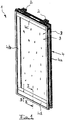
- FIG. 1 is a perspective view of a wall element 1 is shown.
- Several of these wall elements 1 can be arranged in a space adjacent to each other to form a partition wall.
- the guide device 2 has a plurality of rollers which either run only for guiding the wall element 1 in the rail system or can be driven to form an automatically movable partition.
- the wall element 1 essentially comprises two transparent disc elements 3 which are arranged at a parallel distance from each other and which are received in a profile frame 4.
- the profile frame 4 has a rectangular shape and surrounds the disc elements 3.
- the profile frame 4 forms only a small part of the side surface of the wall element 1, so that the width B of the profile frame 4 only a small proportion the lateral overall dimensions of the wall element 1 occupies.
- the profile frame 4 has two vertically extending side frame parts 4a and 4b, which are connected via an upper leg 4c on the upper side and a lower leg 4d on the lower side of the wall element 1.
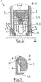
- FIG. 2 follows a cross-sectional view in the cross-sectional plane II-II, which is placed through the lower beam 4d.
- FIG. 2 shows the cross-sectional view through the wall element 1 in the region of the sub-spar 4d according to the section II-II FIG. 1 ,
- the disc elements 3 can be seen, on the left side a thin and right side a thicker disc element 3 is inserted, which in are arranged at a distance from each other.
- the distance of the disc elements 3 to each other is determined by the width of the profile frame 4.
- the disc elements 3 are accommodated as possible at a great distance from each other within a profile frame 4, which is reinforced by a cover band 10, to compensate for the smaller thickness of the disc element 3 on the left side.
- a sound insulation device 5 is integrated, which has at least one sealing element 8 which is movable by means of a drive unit 9 against a bottom 11.
- the sealing element 8 consists at least of a rubber lip, which extends in addition to other sealing elements 12 over the entire width of the wall element 1 away.
- the sealing elements 8 and 12 are received in a receiving frame 13 which is vertically movable by the drive unit 9 against the ground.
- the lower beam 4d has on the outside Clipmannn 6, which are made in one piece with the lower beam 4d.
- the clamping strips 6 have a U-shaped cross section, so that the disk elements 3 can first be inserted into the clamping strips 6. Due to the lower-side arrangements of the clamping strips 6, the disk elements 3 are held therein by their gravitational force, so that subsequently a plug-in seal 7 can be inserted between the clip strip 6 and the disk elements 3 in order to finally receive the disk element 3 in the profile frame 4.
- a detailed view of the arrangement of a plug-in seal 7 in the clip strip 6 is according to the detail III in the FIG. 3 shown in more detail.
- FIG. 3 shows a detailed view of the detail III FIG. 2 ,
- the clip strip 6 is part of the sub-spar 4 d, and has a leg which extends on the outside over the disc element 3 away.
- the clip strip 6 has a latching geometry 14, through which the plug-in seal 7 can be kept.
- This has a recess 15 into which the nose-like locking geometry 14 of the clip strip 6 can hook. Consequently, it is possible to press the plug-in seal 7 between the clip strip 6 and the disc element 3, wherein the plug-in seal 7 is shown in the undeformed state, and the deformation takes place such that the plug-in seal 7 presses against the surface of the disc element 3.
- FIGS. 4a and 4b show a cross-sectional view of the profile frame 4 in the region of the side frame parts 4a and 4b.
- FIG. 4a is a cross section of the left side arranged side frame part 4a and in the FIG. 4b a cross-sectional view of the side frame part 4b of the profile frame 4 is shown.
- the side frame part 4a is designed as a groove part, whereas the side frame part 4b forms a spring part which is intended to engage in the groove part 4a of an adjacent wall element.
- Further sealing elements 16 and 17 are arranged in the tongue and groove geometry in order to make even the joint between the wall elements themselves soundproof.
- the view also shows two disc elements 3, which are received at a distance from each other in the side frame part 4a and 4b.
- the recording takes place via clamping strips 6, which act in the same way with a plug-in seal 7, as already shown by the inclusion of the disc element 3 in the region of the sub-spar according to the FIG. 3 is described.
- the clamping strips 6 in the region of the side frame parts 4a and 4b are designed as individual parts, and have a U-shaped configuration with a short and a long U-leg.
- the short U-leg engages positively in a geometry of the side frame part 4a and 4b, so that the long U-leg extends over a portion on the disc member 3 away.
- FIG. 5 shows a detailed view of the arrangement of the clip strip 6 on the side frame profile 4a according to the detail IV FIG. 4a ,
- the disc element 3 shown here is designed to be thinner, so that in the receiving geometry of the side frame part 4 a a decorative band 10 is used to compensate for the width of the receiving recess for receiving the disc element 3.
- the connection between the plug-in seal 7 and the clip strip 6 takes place in the same way via a latching geometry 14, which is formed on the clip strip 6 and engages positively in a recess 15 which is present in the plug-in seal 7.
- the plug-in seal 7 has an elastic material such as a rubber band and the like, so that this can deform and causes a contact pressure of the disc element 3 against the cover strip 10 or against the profile frame 4 by the deformation.
- the invention is not limited in its execution to the above-mentioned preferred embodiment. Rather, a number of variants is conceivable, which makes use of the illustrated solution even with fundamentally different types of use.
- the disk elements 3 may also consist of a polarization glass in order to temporarily suspend the transparency of the disk elements with appropriate electrical wiring.
- a special gas can be introduced between the two disk elements 3, which enables improved insulation properties for sound insulation.
- the material of the profile frame 4 may be an aluminum extruded profile, which may also be made split and includes a plastic bridge to provide a thermal insulation between the two outer surfaces of the wall element 1.
Description
- Die vorliegende Erfindung betrifft eine Trennwand mit mehreren Wandelementen, die über eine Führungseinrichtung beweglich aufgenommen sind. Die seitlichen Planflächen der Wandelemente sind durch transparente Scheibenelemente gebildet, um eine durchsichtige mobile Trennwand aus mehreren Wandelementen zu schaffen.
- Derartige Wandelemente zur Bildung einer mobilen Trennwand mit transparenten Scheibenelementen finden Anwendung in Räumen wie Ladenlokale zur Bildung einer mobilen Fensterfront, in Geschäften zur variablen Abtrennung von Kundenbereichen, in öffentlichen Gebäuden und insbesondere in Banken, in denen nach Geschäftsschluss ein innerer Teil des Kundenbereiches von einem äußeren Teil abgetrennt wird. Die transparenten Scheibenelemente weisen Beschläge auf, an denen Führungseinrichtungen angebracht sind, um die Wandelemente beispielsweise in einem Deckenschienensystem aufzunehmen und in diesem zu führen. Häufig sind die Scheibenelemente einzeln angeordnet und bilden den Körper des Wandelementes selbst. Die Beschläge sind dann auf der Oberseite und der Unterseite des Scheibenelementes angeordnet, so dass dann, wenn mehrere Wandelemente nebeneinander angeordnet sind, um die Trennwand zu bilden, die Scheibenelemente aus Glas unmittelbar aneinander angrenzen.
- Derartige Trennwände mit mehreren Glaselementen, die aus transparenten Scheibenelementen aufgebaut sind, weisen den Nachteil auf, dass keine Schallisolation ermöglicht ist, da die Scheibenelemente einerseits nur einfach und nicht doppelwandig vorhanden sind und andererseits im Randbereich der Scheibenelemente keine Abdichtung aufweisen. Zwar sind Wandelemente zur Bildung von Trennwänden bekannt, die über Schallisolationseinrichtungen verfügen, derartige Einrichtungen sind jedoch nicht für Wandelemente bekannt, die aus transparenten Scheibenelementen bestehen. Das Problem ergibt sich bereits aus der Integration einer Schallisolationseinrichtung in die Beschläge, die wenigstens oberseitig und unterseitig das Scheibenelement einfassen.
- Ferner sind Trennwände mit mehreren Wandelementen bekannt, wobei die Wandelemente eine Rahmenstruktur aufweisen, in der zugeschnittene Platten eingesetzt sind, die aus MDF-Platten, aus Massivholzplatten oder aus Kunststoffplatten bestehen. Derartige Wandelemente weisen Schallisolationseinrichtungen auf, um eine schalldichte mobile Trennwand zu schaffen. Wandelemente sind ferner mit Fenstern bekannt, die in Gestalt eines Ausschnittes innerhalb der Seitenplatten in diese eingebracht sind. Der Fensterausschnitt innerhalb der Seitenplatten stört dabei nicht die Integration der Schallisolationseinrichtung, die gewöhnlich einen erheblichen Bauraum einnimmt und auf einem Spindelsystem basiert, durch das Dichtelemente sowohl gegen den Boden als auch gegen die Decke des Raumes bewegt werden.
- Die
DE 29822256 U1 zeigt eine mobile Glastrennwand gemäß dem Oberbegriff des Anspruchs 1, bei der über pneumatische betätigbare Huborgane ein weitestgehend automatisches Ausfahren der Dichtleisten ermöglicht wird, wenn die Schiebeelemente zusammenfahren. Diese Glastrennwand kann die erforderlichen Schallwerte nicht erreichen, da die Glasscheiben in einem zu geringen Abstand im Profil angeordnet sind. - In der
EP 1029997 A2 wird eine mobile Trennwand mit Glasscheiben beschrieben, bei der die thermische Abdichtung zwischen den Wandelementen offenbart wird. - Es ist daher die Aufgabe der vorliegenden Erfindung, eine Trennwand mit mehreren Wandelementen zu schaffen, die einen erweiterten Funktionsumfang aufweist und eine erhöhte Schallisolation ermöglicht.
- Diese Aufgabe wird ausgehend von einer Trennwand aus transparenten Wandelementen gemäß des Anspruches 1 in Verbindung mit den kennzeichnenden Merkmalen gelöst. Vorteilhafte Weiterbildungen der Erfindung sind in den abhängigen Ansprüchen angegeben.
- Die erfindungsgemäße Trennwand weist mehrere Wandelemente auf, die über eine Führungseinrichtung beweglich aufgenommen sind, wobei die Wandelemente zwei in einem Abstand parallel zueinander angeordnete transparente Scheibenelemente aufweist, und wobei die Wandelemente einen Profilrahmen zur Aufnahme der Scheibenelemente aufweisen und in dem ferner eine Schallisolationseinrichtung aufgenommen ist, um die Wandelemente wenigstens gegen einen Boden und gegen eine Decke schallisolierend abzudichten.
- Die erfindungsgemäße Trennwand kombiniert die Eigenschaften einer transparenten Trennwand mit den Vorteilen einer Schallisolation. Erst durch die erfindungsgemäße Aufnahme der Scheibenelemente in einem Profilrahmen wird die Voraussetzung geschaffen, eine Schallisolationseinrichtung in den Wandelementen zu integrieren. Die Schallisolation wird einerseits durch die schallisolierende Abdichtung der Wandelemente gegen den Boden und gegen die Decke des Raumes geschaffen, wobei andererseits die planparallele Anordnung von zwei transparenten Scheibenelementen in einem Abstand zueinander zur Schallisolation beiträgt. Dies wird erst durch den Profilrahmen ermöglicht, der in Kombination der transparenten Scheibenelemente das Wandelement bildet. Durch den gegebenen Abstand der beiden transparenten Scheibenelemente zueinander wird der Effekt der Schallisolation verstärkt, wobei ein größerer Abstand zwischen den Scheibenelementen zu besseren Werten der Schallisolation führt.
- Je größer der Abstand der Scheibenelemente zueinander ist, desto größer ist die Wirkung der Schallisolation. Hingegen sollte das Wandelement ein gegebenes Breitenmaß nicht übersteigen, so dass es von Vorteil ist, die Scheibenelemente im Wandelement möglichst außenseitig anzuordnen. Der Profilrahmen sollte folglich nicht wesentlich über die Außenflächen der Scheibenelemente hinausragen. Dabei weist der Abstand der beiden im Profilrahmen aufgenommen Glasscheiben einen Wert von wenigstens 80 mm auf, wobei das Wandelement insgesamt ein Dickenmaß von 100 mm nicht überschreitet.
- Gemäß einer vorteilhaften Ausführungsform sind die Seitenflächen des Wandelementes überwiegend durch die Scheibenelemente gebildet, wobei der Profilrahmen die Scheibenelemente nur randseitig umgibt und diese einfasst. Damit wird eine klare Unterscheidung des erfindungsgemäßen Wandelementes von bekannten Wandelementen geschaffen, die als Seitenflächen in einem Rahmen eingefasste nicht-transparente Platten aufweisen und die einen Fensterausschnitt besitzen. Derartige herkömmliche Wandelemente besitzen Seitenflächen, die überwiegend durch die nichttransparenten Seitenplatten gebildet sind. Vorliegend besitzt das erfindungsgemäße Wandelement jedoch lediglich einen Profilrahmen, der derart schmal ausgeführt ist, dass dieser nur randseitig in Erscheinung tritt, und die Scheibenelemente im Profilrahmen eingefasst sind. Das Verhältnis zwischen der Seitenfläche, die durch den Profilrahmen gebildet wird, verglichen zur Seitenfläche, die durch das Scheibenelement gebildet wird, kann mit einem Fensterflügel eines Gebäudes verglichen werden. Bei einem Fensterflügel fasst ein Fensterrahmen die Fensterscheibe lediglich randseitig ein, ohne dass der Fensterrahmen einen wesentlichen Anteil an der Seitenfläche des Fensters bildet.
- Die Scheibenelemente sind aus Glasscheiben gebildet, wobei bevorzugt wenigstens eine der beiden Scheibenelemente eine Einfachglasscheibe oder auch eine Doppelglasscheibe aufweisen kann. Durch Verwendung von Doppelglasscheiben wird neben einer verbesserten Schallisolation auch eine Wärmeisolation ermöglicht, sofern die erfindungsgemäße Trennwand die Funktion einer Wärmedämmung erfüllen muss. Der Profilrahmen kann dabei ferner eine thermische Trennung aufweisen, in dem dieser beispielsweise sowohl ein innenseitiges als auch ein außenseitiges Aluminiumprofil besitzt, die über Kunststoffstege innenseitig zusammengehalten sind. Damit entsteht eine Barriere gegen einen Wärmefluss von einer warmen zu einer kalten Seite, die durch die Trennwand getrennt sind. Dabei kann es hinreichend sein, zumindest eine der beiden Scheibenelemente als Doppelglasscheibe auszuführen, wobei die zweite Glasscheibe eine Einfachglasscheibe sein kann.
- Es ist weiterhin möglich die Glasscheiben als Einfachglasscheiben auszubilden und entweder mit einer gleichen oder mit einer unterschiedlichen Dicke zu kombinieren. Beispielsweise ist es von Vorteil, Glasscheibendicken von 6 mm und 6 mm zu kombinieren, wobei auch eine Kombination von 8 mm und 10 mm möglich ist, die eine verbesserte Schallisolation ermöglicht. Die Kombination von unterschiedlichen Glasscheibendicken führt zu geringeren Resonanzeffekten, wodurch wiederum die Schallisolation weiter verstärkt werden kann.
- Eine mögliche Ausführungsform des Profilrahmens besitzt vertikal verlaufende Seitenrahmenteile, die nach Art einer Nut-Feder-Verbindung derart kombiniert sind, dass mehrere Wandelemente nebeneinander angeordnet werden können und einen Formschluss bilden. Folglich weist ein Wandelement ein erstes vertikal verlaufendes Seitenrahmenteil auf einer ersten Seite auf, das eine Nut umfasst, wobei das gegenüberliegende zweite vertikal verlaufende Rahmenteil auf der zweiten Seite eine Federgeometrie besitzt. In der Nut-Feder-Fügegeometrie können wiederum Dichtelemente zur Verbesserung der Schallisolation vorgesehen sein. Der Profilrahmen besteht auf der oberen Seite aus einem horizontal verlaufendem Oberholm und auf der Bodenseite auf einem horizontal verlaufendem Unterholm. Im Ergebnis wird ein zumeist rechteckiger Profilrahmen gebildet, wobei die vertikal verlaufenden Seitenrahmenteile mit den jeweiligen Ober- und Unterholmen verbunden sind. Die Verbindung kann über Winkelprofile erfolgen, wobei diese aus einem festeren Werkstoff, beispielsweise einem Stahlwerkstoff, ausgebildet sein können, da das Gewicht der Scheibenelemente über die Winkelprofile getragen wird, denn die Wandelemente sind meist mit einer Führungseinrichtung aufgenommen, die an der Decke des Raumes angebracht ist. Derartige Wandelemente können Höhen von über vier Metern aufweisen, so dass bei zwei im Profilrahmen eingesetzten Glasscheiben größerer Dicke ein beträchtliches Gewicht entsteht, das zunächst vom Unterholm aufgenommen wird und über die Winkelprofile in die vertikal verlaufenden Seitenrahmenteile eingeleitet wird.
- Gemäß der vorliegenden Erfindung weist die Trennwand eine Schallisolationseinrichtung auf, die im Oberholm und/oder im Unterholm angeordnet ist. Die Schallisolationseinrichtung besitzt Dichtelemente, die jeweils aus dem Oberholm gegen die Decke und aus dem Unterholm gegen den Boden fahrbar sind. Die Dichtelemente müssen im Ober- und Unterholm verfahrbar angeordnet sein, da die Dichtelemente erst nach Erreichen der Endposition des Wandelementes in der Trennwand gegen die Decke und den Boden verfahren werden. Folglich kann das Wandelement innerhalb der Führungseinrichtung bewegt werden, ohne dass die Dichtelemente gegen die Decke und den Boden abdichten.
- Zum Verfahren der Dichtelemente ist erfindungsgemäß vorgesehen, dass in einem Wandelement eine erste Antriebseinheit im Oberholm und eine zweite Antriebseinheit im Unterholm vorgesehen ist, die getrennt voneinander ein jeweiliges Dichtelement sowohl gegen die Decke als auch gegen den Boden verfahren. Im Unterschied zu herkömmlichen Wandelementen, in denen eine einzige Antriebseinheit sowohl ein erstes Dichtelement gegen die Decke als auch ein weiteres zweites Dichtelement gegen den Boden verfährt, weist das erfindungsgemäße Wandelement getrennte Antriebseinheiten für die Dichtelemente zum Abdichten gegen die Decke und gegen den Boden auf. Um die erfindungsgemäße Ausführung des Wandelementes mit einem Profilrahmen zu schaffen, in dem die Antriebseinheiten oberseitig und unterseitig eingebracht sind, müssen die Antriebseinheiten dem verfügbaren Bauraum innerhalb des Oberholms und des Unterholms angepasst sein. Eine alternative Ausführungsform einer Antriebseinheit kann ein Spindelsystem umfassen, welches nur einen Antrieb aufweist, der in einem der vertikal verlaufenden Seitenrahmenteile integriert ist, und sowohl mit dem deckenseitigen als auch mit dem bodenseitigen Dichtelement zusammenwirkt. Nur dann kann der Antrieb der Dichtelemente oberseitig und unterseitig auf eine Antriebseinheit reduziert werden. Unabhängig von der Anordnung der Antriebseinheit in den Seitenrahmenteilen oder im Ober- und Unterholm ist diese zumindest aus der Mitte des Wandelementes verlagert worden. Folglich ist die Transparenz durch die Wandelemente nicht durch die Anordnung der Antriebseinheit behindert.
- Vorteilhafterweise ist der Profilrahmen durch eine Breite bestimmt, die einen Wert von 200 mm, bevorzugt einen Wert von 150 mm und besonders bevorzugt einen Wert von 120 mm nicht übersteigt. Nur so kann gewährleistet sein, dass die Seitenfläche des Wandelementes überwiegend durch das Scheibenelement gebildet wird. Insbesondere die Brüstungshöhe vom Boden bis zur Oberkante des Profilrahmens im Bereich des Unterholms ist mit einem Wert von 120 mm begrenzt, wobei eine geringe Breite des Profilrahmens zu einem wünschenswerten, filigranen Erscheinungsbild der Trennwand beiträgt.
- Gemäß einer weiteren vorteilhaften Ausführungsform sind Clipleisten vorgesehen, durch die die Scheibenelemente im Profilrahmen aufgenommen sind. Die Clipleisten werden außenseitig am Profilrahmen angeordnet, so dass beide Scheibenelemente durch die Clipleisten mittel eines elastischen Andruckes gegen den Profilrahmen gehalten werden. Die Clipleiste auf der Seite des Unterholms kann einteilig mit dem Unterholm ausgeführt sein, so dass die Scheibenelemente zunächst in die unterseitige Clipleiste eingesetzt bzw. eingestellt werden können. Nachfolgend werden die Clipleisten an den Seitenrahmenteilen sowie am Oberholm eingesetzt, um das Scheibenelement im Profilrahmen zu befestigen. Die Clipleisten, die an den vertikal verlaufenden Seitenrahmenteilen sowie am Oberholm angeordnet sind, weisen ein U-förmiges Strangprofil auf. Das U-förmige Strangprofil bewirkt mit einem ersten U-Schenkel einen Formschluss im Seitenrahmenteil, und erzeugt mit einem zweiten U-Schenkel einen Andruck des Scheibenelementes gegen den Profilrahmen. Dieser zweite U-Schenkel ist gegenüber dem ersten U-Schenkel länger ausgeführt und erstreckt sich abschnittsweise über das Scheibenelement. Um eine elastische Aufnahme der Scheibenelemente im Profilrahmen zu ermöglichen, sind Steckdichtungen vorgesehen, die mit den Clipleisten zusammenwirken. Die Steckdichtungen werden auf dem gesamten Umfang des Profilrahmens zwischen dem zweiten Schenkel der Clipleiste und dem Scheibenelement eingedrückt, und können in der Clipleiste verrasten. Die Steckdichtungen können aus einem gummiartigen Material bestehen, um sowohl eine Abdichtung gegen Verunreinigungen zu schaffen, die zwischen die Scheibenelemente gelangen können, als auch eine Nachgiebigkeit zwischen dem Profilrahmen und dem Scheibenelement zu ermöglichen, um beispielsweise Wärmedehnungen auszugleichen.
- Das Wandelement weist insgesamt ein Dickenmaß von etwa 100 mm auf. Damit wird die Stapelhöhe der Wandelemente in einer Parkposition verringert. Ferner trägt eine geringere Dicke des Wandelementes zu einem filigraneren Erscheinungsbild bei, wobei es zugleich wünschenswert ist, die Scheibenelemente mit einem großen Abstand zueinander im Profilrahmen aufzunehmen. Folglich weisen die Clipleisten nur eine geringe Höhe über dem Scheibenelement auf, die geringer ist als die Dicke des Scheibenelementes, um die Gesamtdicke der Wandelemente nicht unnötig zu vergrößern.
- Weitere, die Erfindung verbessernde Maßnahmen werden nachstehend gemeinsam mit der Beschreibung eines bevorzugten Ausführungsbeispiels der Erfindung anhand der Figuren näher dargestellt.
- Es zeigen:
- Figur 1:
- eine perspektivische Ansicht eines erfindungsgemäßen Wandelementes zur Bildung einer mobilen Trennwand;
- Figur 2:
- eine Querschnittsansicht in der Querschnittsebene, die in
Figur 1 mit II-II gekennzeichnet ist; - Figur 3:
- eine Detailansicht der Anordnung der Clipleiste am Profilrahmen mit einer zugeordneten Steckdichtung gemäß des Details III, das in der
Figur 2 gezeigt ist; - Figur 4a:
- eine Querschnittsansicht des Profilrahmens im Bereich eines vertikal verlaufenden Seitenrahmenteils, das als Nut ausgeführt ist;
- Figur 4b:
- eine Querschnittsansicht durch ein vertikal verlaufendes Seitenrahmenteil, dass als Feder ausgeführt ist und
- Figur 5:
- eine Detailansicht der Anordnung einer Clipleiste mit einer Steckdichtung im Bereich eines Seitenrahmenteils gemäß des Details IV aus der
Figur 4a . - In
Figur 1 ist eine perspektivische Ansicht eines Wandelementes 1 dargestellt. Mehrere dieser Wandelemente 1 können in einem Raum angrenzend aneinander angeordnet werden, um eine Trennwand zu bilden. Um die Wandelemente 1 zu verfahren, besitzen diese eine Führungseinrichtung 2, über die die Wandelemente 1 in einem Schienensystem verfahrbar sind, dass beispielsweise in der Decke eines Raumes integriert ist. Die Führungseinrichtung 2 weist eine Vielzahl von Rollen auf, die entweder nur zur Führung des Wandelementes 1 im Schienensystem laufen oder angetrieben sein können, um eine automatisch verfahrbare Trennwand zu bilden. Das Wandelement 1 weist im Wesentlichen zwei in einem parallelen Abstand zueinander angeordnete transparente Scheibenelemente 3 auf, die in einem Profilrahmen 4 aufgenommen sind. Der Profilrahmen 4 besitzt eine rechteckige Form und umrandet die Scheibenelemente 3. Wie in der perspektivischen Ansicht des Wandelementes 1 gezeigt, bildet der Profilrahmen 4 lediglich einen geringen Teil der Seitenfläche des Wandelementes 1, so dass die Breite B des Profilrahmens 4 nur einen geringen Anteil an den seitlichen Gesamtabmessungen des Wandelementes 1 einnimmt. Der Profilrahmen 4 weist zwei vertikal verlaufende Seitenrahmenteile 4a und 4b auf, die über einen Oberholm 4c auf der oberen Seite und einen Unterholm 4d auf der unteren Seite des Wandelementes 1 verbunden sind. InFigur 2 folgt eine Querschnittsansicht in der Querschnittsebene II-II, der durch den Unterholm 4d gelegt ist. -
Figur 2 zeigt die Querschnittsansicht durch das Wandelement 1 im Bereich des Unterholms 4d gemäß des Schnittes II-II ausFigur 1 . Im Querschnitt sind die Scheibenelemente 3 erkennbar, wobei linksseitig ein dünnes und rechtsseitig ein dickeres Scheibenelement 3 eingesetzt ist, die in einem Abstand zueinander angeordnet sind. Der Abstand der Scheibenelemente 3 zueinander wird durch die Breite des Profilrahmens 4 bestimmt. Dabei sind die Scheibenelemente 3 möglichst in einem großen Abstand zueinander innerhalb eines Profilrahmens 4 aufgenommen, was durch ein Vorlegeband 10 noch verstärkt ist, um die geringere Dicke des Scheibenelementes 3 auf der linken Seite auszugleichen. - Innerhalb des Unterholmes 4d des Profilrahmens 4 ist eine Schallisolationseinrichtung 5 integriert, die wenigstens ein Dichtelement 8 aufweist, das mittels einer Antriebseinheit 9 gegen einen Boden 11 verfahrbar ist. Das Dichtelement 8 besteht wenigstens aus einer Gummilippe, die sich neben weiteren Dichtelementen 12 über der gesamten Breite des Wandelementes 1 hinweg erstreckt. Die Dichtelemente 8 und 12 sind in einem Aufnahmerahmen 13 aufgenommen, der durch die Antriebseinheit 9 vertikal gegen den Boden bewegbar ist.
- Der Unterholm 4d weist außenseitige Clipleisten 6 auf, die einteilig mit dem Unterholm 4d ausgeführt sind. Die Clipleisten 6 besitzen einen U-förmigen Querschnitt, so dass die Scheibenelemente 3 zunächst in die Clipleisten 6 eingesetzt werden können. Aufgrund der unterseitigen Anordnungen der Clipleisten 6 sind die Scheibenelemente 3 in diesem durch ihre Schwerkraft gehalten, so dass anschließend eine Steckdichtung 7 zwischen der Clipleiste 6 und den Scheibenelementen 3 eingesetzt werden kann, um das Scheibenelement 3 endgültig in dem Profilrahmen 4 aufzunehmen. Eine detaillierte Ansicht der Anordnung einer Steckdichtung 7 in der Clipleiste 6 ist gemäß des Details III in der
Figur 3 genauer dargestellt. -
Figur 3 zeigt eine detaillierte Ansicht des Details III ausFigur 2 . Die Clipleiste 6 ist Bestandteil des Unterholms 4d, und besitzt einen Schenkel, der sich außenseitig über das Scheibenelement 3 hinweg erstreckt. Endseitig besitzt die Clipleiste 6 eine Rastgeometrie 14, durch die die Steckdichtung 7 gehalten werden kann. Diese weist eine Vertiefung 15 auf, in die die nasenartige Rastgeometrie 14 der Clipleiste 6 einhaken kann. Folglich besteht die Möglichkeit, die Steckdichtung 7 zwischen die Clipleiste 6 und das Scheibenelement 3 einzudrücken, wobei die Steckdichtung 7 in unverformtem Zustand gezeigt ist, und die Verformung derart stattfindet, dass die Steckdichtung 7 gegen die Oberfläche des Scheibenelementes 3 drückt. - Die
Figuren 4a und 4b zeigen eine quergeschnittene Ansicht des Profilrahmens 4 im Bereich der Seitenrahmenteile 4a und 4b. In derFigur 4a ist ein Querschnitt des linksseitig angeordneten Seitenrahmenteiles 4a und in derFigur 4b ist eine quer geschnittene Ansicht des Seitenrahmenteiles 4b des Profilrahmens 4 gezeigt. Das Seitenrahmenteil 4a ist als Nut-Teil ausgeführt, wohingegen das Seitenrahmenteil 4b einen Feder-Teil bildet, der zum Eingriff in den Nut-Teil 4a eines benachbarten Wandelementes bestimmt ist. Weitere Dichtelemente 16 und 17 sind in der Feder-Nut-Geometrie angeordnet, um auch die Fügestelle zwischen den Wandelementen selbst schalldicht zu gestalten. - Die Ansicht zeigt ferner zwei Scheibenelemente 3, die in einem Abstand zueinander im Seitenrahmenteil 4a und 4b aufgenommen sind. Die Aufnahme erfolgt über Clipleisten 6, die auf gleiche Weise mit einer Steckdichtung 7 zusammen wirken, wie dies bereits durch die Aufnahme des Scheibenelementes 3 im Bereich des Unterholms gemäß der
Figur 3 beschrieben ist. Jedoch sind die Clipleisten 6 im Bereich der Seitenrahmenteile 4a und 4b als Einzelteile ausgeführt, und besitzen eine U-förmige Gestalt mit einem kurzen und einem langen U-Schenkel. Der kurze U-Schenkel greift formschlüssig in eine Geometrie des Seitenrahmenteils 4a und 4b ein, so dass sich der lange U-Schenkel über einen Abschnitt über das Scheibenelement 3 hinweg erstreckt. Endseitig am langen U-Schenkel der Clipleiste 6 ist wiederum eine Steckdichtung 7 eingesetzt, die auf gleiche Weise ausgeführt ist, wie die Steckdichtung 7 im Bereich des Unterholms. - Die
Figur 5 zeigt eine Detailansicht der Anordnung der Clipleiste 6 am Seitenrahmenprofil 4a gemäß des Details IV ausFigur 4a . Das hierin gezeigte Scheibenelement 3 ist dünner ausgeführt, so dass in der Aufnahmegeometrie des Seitenrahmenteils 4a ein Vorlegeband 10 eingesetzt ist, um die Breite der Aufnahmeaussparung zur Aufnahme des Scheibenelementes 3 auszugleichen. - Die Verbindung zwischen der Steckdichtung 7 und der Clipleiste 6 erfolgt auf gleiche Weise über eine Rastgeometrie 14, die an der Clipleiste 6 ausgebildet ist und in eine Vertiefung 15 formschlüssig eingreift, die in der Steckdichtung 7 vorhanden ist. Die Steckdichtung 7 weist ein elastisches Material wie ein Gummiband und dergleichen auf, so dass sich dieses verformen kann und durch die Verformung ein Anpressdruck des Scheibenelementes 3 gegen das Vorlegeband 10 bzw. gegen den Profilrahmen 4 hervorruft.
- Die Erfindung beschränkt sich in ihrer Ausführung nicht auf das vorstehend angegebene bevorzugte Ausführungsbeispiel. Vielmehr ist eine Anzahl von Varianten denkbar, welche von der dargestellten Lösung auch bei grundsätzlich anders gearteten Ausführungen Gebrauch macht. Insbesondere können die Scheibenelemente 3 auch aus einem Polarisationsglas bestehen, um mit entsprechender elektrischer Beschaltung die Transparenz der Scheibenelemente vorübergehend aufzuheben. Ferner kann zwischen den beiden Scheibenelementen 3 ein spezielles Gas eingeleitet werden, dass verbesserte Isolationseigenschaften zur Schallisolation ermöglicht. Das Material der Profilrahmen 4 kann ein Aluminium-Strangpressprofil sein, welches auch geteilt ausgeführt sein kann und eine Kunststoffbrücke umfasst, um eine Wärmeisolation zwischen den beiden Außenflächen des Wandelementes 1 zu schaffen.
-
- 1
- Wandelement
- 2
- Führungseinrichtung
- 3
- Scheibenelement
- 4
- Profilrahmen
- 4a
- Seitenrahmenteil
- 4b
- Seitenrahmenteil
- 4c
- Oberholm
- 4d
- Unterholm
- 5
- Schallisolationseinrichtung
- 6
- Clipleiste
- 7
- Steckdichtung
- 8
- Dichtelement
- 9
- Antriebseinheit
- 10
- Vorlegeband
- 11
- Boden
- 12
- Dichtelement
- 13
- Aufnahmerahmen
- 14
- Rastgeometrie
- 15
- Vertiefung
- 16
- Dichtelement
- 17
- Dichtelement
- B
- Breite des Profilrahmens
Claims (14)
- Trennwand mit mehreren Wandelementen (1), die über eine Führungseinrichtung (2) beweglich aufgenommen sind, wobei die Wandelemente (1) zwei in einem Abstand parallel zueinander angeordnete transparente Scheibenelemente (3) aus Glas aufweisen, und wobei die Wandelemente (1) einen Profilrahmen (4) zur Aufnahme der Scheibenelemente (3) aufweisen und in dem ferner eine Schallisolationseinrichtung (5) aufgenommen ist, um das Wandelement (1) wenigstens gegen einen Boden und gegen eine Decke schallisolierend abzudichten, dadurch gekennzeichnet, dass die Scheibenelemente (3) außenseitig am Wandelement (1) angeordnet sind und in einem Abstand von wenigstens 80 mm zueinander im Profilrahmen aufgenommen sind
- Trennwand nach Anspruch 1, dadurch gekennzeichnet, dass die Seitenfläche des Wandelementes (1) überwiegend durch die Scheibenelemente (3) gebildet ist, wobei der Profilrahmen (4) die Scheibenelemente (3) nur randseitig umgibt und diese einfasst.
- Trennwand nach Anspruch 1, dadurch gekennzeichnet, dass wenigstens eines der Scheibenelemente (3) eine Einfachglasscheibe oder eine Doppelglasscheibe aufweist.
- Trennwand nach Anspruch 3, dadurch gekennzeichnet, dass die Scheibenelemente (3) als Einfachglasscheiben ausgebildet sind und in Glasscheibendicken von etwa 6mm und etwa 6mm oder von etwa 10mm und etwa 8mm kombiniert im Profilrahmen (4) aufgenommen sind.
- Trennwand nach einem der vorgenannten Ansprüche, dadurch gekennzeichnet, dass der Profilrahmen (4) vertikal verlaufende Seitenrahmenteile (4a, 4b) und einen deckenseitigen, horizontal verlaufenden Oberholm (4c) und einen bodenseitigen, horizontal verlaufenden Unterholm (4d) aufweist.
- Trennwand nach Anspruch 5, dadurch gekennzeichnet, dass die Schallisolationseinrichtung (5) im Oberholm (4c) und/oder im Unterholm (4d) aufgenommene Dichtelemente (8) aufweist, die aus dem Oberholm (4c) gegen die Decke und aus dem Unterholm (4d) gegen den Boden fahrbar sind.
- Trennwand nach Anspruch 5 oder 6, dadurch gekennzeichnet, dass in einem Wandelement (1) eine erste Antriebseinheit (9) im Oberholm und eine zweite Antriebseinheit (9) im Unterholm vorgesehen ist, wobei die Dichtelemente (8) mittels der Antriebseinheiten (9) gegen die Decke und/oder gegen den Boden verfahrbar sind.
- Trennwand nach einem der vorgenannten Ansprüche, dadurch gekennzeichnet, dass der Profilrahmen (4) durch eine Breite (B) vom eingefassten Scheibenelement (3) bis zum Rand des Wandelementes (1) hin bestimmt ist, die einen Wert von 200mm, bevorzugt von 150mm und besonders bevorzugt von 120mm nicht übersteigt, um die Seitenfläche des Wandelementes (1) überwiegend durch das Scheibenelement (3) zu bilden.
- Trennwand nach einem der vorgenannten Ansprüche, dadurch gekennzeichnet, dass Clipleisten (6) vorgesehen sind, durch die die Scheibenelemente (3) im Profilrahmen (4) aufgenommen sind.
- Trennwand nach Anspruch 9, dadurch gekennzeichnet, dass die Clipleisten (6) außenseitig am Profilrahmen (4) angeordnet sind, und beide Scheibenelemente (3) durch die Clipleisten (6) mittels elastischen Andrucks gegen den Profilrahmen (4) gehalten sind.
- Trennwand nach Anspruch 10, dadurch gekennzeichnet, dass das seitliche und zur Dicke des Wandelementes (1) beitragende Höhenmaß der Clipleisten (6) über dem Scheibenelement (3) geringer ist als die Dicke eines Scheibenelementes (3).
- Trennwand nach einem der Ansprüche 10 bis 11, dadurch gekennzeichnet, dass die Clipleisten (6), die am Ober- und/oder am Unterholm (4c, 4d) angeordnet sind, als Teil des Profilrahmens (4) ausgebildet sind, wobei Steckdichtungen (7) vorgesehen sind, die zwischen der Clipleiste (6) und dem Scheibenelement (3) einsetzbar sind und eine Druckvorspannung des Scheibenelementes (4) gegen den Profilrahmen (4) erzeugen.
- Trennwand nach einem der Ansprüche 10 bis 12, dadurch gekennzeichnet, dass die Clipleisten (6), die an den vertikal verlaufenden Seitenrahmenteilen (4a, 4b) und am Oberholm (4c) angeordnet sind, ein U-förmiges Strangprofil aufweisen, das mit einem ersten U-Schenkel einen Formschluss im Seitenrahmenteil (4a, 4b) bzw. zum Oberholm (4c) bildet und mit einem zweiten U-Schenkel einen Andruck des Scheibenelementes (3) gegen den Profilrahmen (4) erzeugt.
- Trennwand nach einem der vorgenannten Ansprüche, dadurch gekennzeichnet, dass das Wandelement (1) ein Dickenmaß aufweist, das kleiner als 120mm und bevorzugt kleiner als oder gleich 100mm ist.
Priority Applications (1)
| Application Number | Priority Date | Filing Date | Title |
|---|---|---|---|
| EP11001243.2A EP2372032B1 (de) | 2008-06-11 | 2009-05-29 | Trennwand aus transparenten Wandelementen |
Applications Claiming Priority (2)
| Application Number | Priority Date | Filing Date | Title |
|---|---|---|---|
| DE102008027821A DE102008027821A1 (de) | 2008-06-11 | 2008-06-11 | Trennwand aus transparenten Wandelementen |
| PCT/EP2009/003854 WO2009149839A2 (de) | 2008-06-11 | 2009-05-29 | Trennwand aus transparenten wandelementen |
Related Child Applications (3)
| Application Number | Title | Priority Date | Filing Date |
|---|---|---|---|
| EP11001243.2A Division-Into EP2372032B1 (de) | 2008-06-11 | 2009-05-29 | Trennwand aus transparenten Wandelementen |
| EP11001243.2A Division EP2372032B1 (de) | 2008-06-11 | 2009-05-29 | Trennwand aus transparenten Wandelementen |
| EP11001243.2 Division-Into | 2011-02-16 |
Publications (3)
| Publication Number | Publication Date |
|---|---|
| EP2307629A2 EP2307629A2 (de) | 2011-04-13 |
| EP2307629B1 true EP2307629B1 (de) | 2017-05-17 |
| EP2307629B2 EP2307629B2 (de) | 2023-08-02 |
Family
ID=41317697
Family Applications (2)
| Application Number | Title | Priority Date | Filing Date |
|---|---|---|---|
| EP09761402.8A Active EP2307629B2 (de) | 2008-06-11 | 2009-05-29 | Trennwand aus transparenten wandelementen |
| EP11001243.2A Active EP2372032B1 (de) | 2008-06-11 | 2009-05-29 | Trennwand aus transparenten Wandelementen |
Family Applications After (1)
| Application Number | Title | Priority Date | Filing Date |
|---|---|---|---|
| EP11001243.2A Active EP2372032B1 (de) | 2008-06-11 | 2009-05-29 | Trennwand aus transparenten Wandelementen |
Country Status (6)
| Country | Link |
|---|---|
| US (1) | US20110078960A1 (de) |
| EP (2) | EP2307629B2 (de) |
| CN (1) | CN102057113A (de) |
| AU (1) | AU2009257001A1 (de) |
| DE (1) | DE102008027821A1 (de) |
| WO (1) | WO2009149839A2 (de) |
Families Citing this family (5)
| Publication number | Priority date | Publication date | Assignee | Title |
|---|---|---|---|---|
| US8839592B2 (en) * | 2012-08-01 | 2014-09-23 | Dana Francis Foran | Dust free construction barrier system |
| ES2700923T3 (es) * | 2014-07-11 | 2019-02-20 | Isoclima Spa | Ventana conmutable |
| US10041249B1 (en) * | 2015-07-31 | 2018-08-07 | Timothy Hebert | Adjustable barrier for partitioning a building space |
| CA2997063A1 (en) * | 2017-03-01 | 2018-09-01 | Abatement Technologies, Inc. | Rigid panel containment system and related methods |
| US20230160195A1 (en) * | 2023-01-23 | 2023-05-25 | Nan Ya Plastics Corporation | Collapsable living compartment |
Citations (2)
| Publication number | Priority date | Publication date | Assignee | Title |
|---|---|---|---|---|
| EP0629752A1 (de) | 1993-05-25 | 1994-12-21 | Rosconi Ag | Mobile Trennwand |
| EP1029997A2 (de) | 1999-02-19 | 2000-08-23 | DORMA GmbH + Co. KG | Mobile Trennwand mit Abschlussprofil |
Family Cites Families (92)
| Publication number | Priority date | Publication date | Assignee | Title |
|---|---|---|---|---|
| US3072975A (en) * | 1958-12-08 | 1963-01-15 | Richards Wilcox Mfg Co | Sealing mechanism for movable partition panels, doors and the like |
| US3049195A (en) * | 1959-01-09 | 1962-08-14 | Nat Res Dev | Demountable partitions |
| US3110131A (en) * | 1959-05-27 | 1963-11-12 | Jeffress Dyer Inc | Building construction |
| FR1267535A (fr) * | 1960-09-15 | 1961-07-21 | Cadres préfabriqués monolithiques avec éléments d'articulation et d'étanchéité destinés à constituer des dormants et battants | |
| US3335532A (en) * | 1964-01-08 | 1967-08-15 | Barrie B Greenbie | Movable partition or wall |
| US3226777A (en) * | 1964-03-23 | 1966-01-04 | Kollsman Paul | Flush closing sliding door assemblies |
| US3387418A (en) * | 1964-07-15 | 1968-06-11 | James W. Tyrer | Molding and partition assembly system |
| US3341992A (en) * | 1964-10-07 | 1967-09-19 | Robert Haws Co | Portable room dividing panel |
| US3295257A (en) * | 1965-03-12 | 1967-01-03 | Hough Mfg Corp | Wall panel assembly |
| NO117609B (de) * | 1966-07-01 | 1969-09-01 | Knag As A | |
| US3400504A (en) * | 1966-07-06 | 1968-09-10 | Ray H. Neisewander | Movable wall partition |
| US3557499A (en) * | 1968-09-16 | 1971-01-26 | Formica Corp | Movable wall panel system |
| US3587205A (en) * | 1968-10-29 | 1971-06-28 | Joseph Henry Gartside | Buildings |
| US3614050A (en) * | 1969-10-07 | 1971-10-19 | William Greenhalgh | Reusable forming unit |
| US3638376A (en) * | 1970-01-05 | 1972-02-01 | Hough Mfg Corp | Portable partition |
| US3755968A (en) * | 1972-01-20 | 1973-09-04 | Hough Mfg Corp | Floating constant contact seal for operable partitions |
| US3798839A (en) * | 1972-08-31 | 1974-03-26 | Industrial Acoustics Co | Movable wall panel |
| US3967420A (en) * | 1974-04-30 | 1976-07-06 | Papsco, Inc. | Portable wall system and method of installing same |
| US4073092A (en) * | 1975-06-27 | 1978-02-14 | Hough Manufacturing Corporation | Lost motion suspension system for operable partitions |
| US4084366A (en) * | 1975-11-14 | 1978-04-18 | Haworth Mfg., Inc. | Sound absorbing panel |
| US4031664A (en) * | 1976-01-20 | 1977-06-28 | United States Gypsum Company | Suspension system for sound absorption panels |
| US4014137A (en) * | 1976-03-08 | 1977-03-29 | Hough Manufacturing Corporation | Drop action panel arrangement for operable partitions |
| JPS574175Y2 (de) * | 1976-08-11 | 1982-01-26 | ||
| US4038790A (en) * | 1976-09-16 | 1977-08-02 | Paisley John C | Partition structure |
| US4103463A (en) * | 1976-09-28 | 1978-08-01 | Panelfold Doors, Inc. | Portable wall system |
| US4454690A (en) * | 1976-09-28 | 1984-06-19 | Panelfold, Inc. | Portable and operable wall system |
| US4277920A (en) * | 1976-09-28 | 1981-07-14 | Panelfold Doors, Inc. | Portable and operable wall systems |
| DE2811604C3 (de) * | 1978-03-17 | 1980-12-11 | Dornier System Gmbh, 7990 Friedrichshafen | Rahmen |
| US4227355A (en) * | 1978-03-30 | 1980-10-14 | United States Gypsum Company | Support system for sound absorbing panels |
| US4263761A (en) * | 1979-02-09 | 1981-04-28 | Kristoff Kim C | Portable acoustical panel system |
| DE3011946C2 (de) * | 1980-03-27 | 1985-03-21 | Golde GmbH Spritzgußwerk, 8192 Geretsried | Schiebefenster oder -tür |
| US4395854A (en) * | 1980-12-15 | 1983-08-02 | American Standard Inc. | Universal latch means for drop seal assembly for a moveable wall |
| US4612744A (en) * | 1981-08-07 | 1986-09-23 | Shamash Jack E | Method, components, and system for assembling buildings |
| US4443978A (en) * | 1982-12-14 | 1984-04-24 | Butler-Merritt Inc. | Movable thermal barrier for solar heated building |
| US4535578A (en) * | 1983-06-09 | 1985-08-20 | American Standard Inc. | Seal-actuating mechanism for a wall panel |
| CH666514A5 (de) * | 1984-05-24 | 1988-07-29 | Heinrich Saelzer | Rahmen fuer mit einer plattenfoermigen fuellung versehene bauteile. |
| US4703598A (en) * | 1986-04-28 | 1987-11-03 | Haworth, Inc. | Combined noise seal and retainer for panel |
| DE3619392A1 (de) * | 1986-06-09 | 1987-12-10 | Hueppe Gmbh | Zweischaliges teleskopelement einer beweglichen trennwand |
| US5524402A (en) * | 1988-11-16 | 1996-06-11 | Sykes; Christopher C. | Partition structures and frame elements therefor |
| US5214889A (en) * | 1990-01-18 | 1993-06-01 | Herman Miller, Inc. | Electrified wall panel system |
| US5042555A (en) * | 1990-10-01 | 1991-08-27 | Modernfold, Inc. | Floor-supported movable wall panel with height adjustment system |
| JPH0552072A (ja) * | 1991-08-16 | 1993-03-02 | Masaaki Kamezaki | 大形冷凍庫等用スライデイング式ドア |
| EP0642617A1 (de) * | 1992-05-18 | 1995-03-15 | WHALLEY, Kevin | Steinverkleidungssystem für Gebäude |
| US5577348A (en) * | 1993-05-25 | 1996-11-26 | Rosconi Ag | Partition wall with sliding termination panel |
| US5481834A (en) * | 1994-04-08 | 1996-01-09 | Hufcor, Inc. | Fire-rated panel |
| US5603192A (en) * | 1995-04-03 | 1997-02-18 | Advanced Equipment Corporation | Operable wall panel mounting apparatus |
| US6141926A (en) * | 1995-10-26 | 2000-11-07 | Tetrad Marketing/Sales Ltd. | Panel construction and connection system |
| CH689233A5 (de) * | 1996-05-07 | 1998-12-31 | Dorma Tuerautomatik Ag | Schiebewand |
| US6223485B1 (en) * | 1996-06-07 | 2001-05-01 | Herman Miller, Inc. | Wall panel system |
| ATE221949T1 (de) * | 1996-06-21 | 2002-08-15 | Dorma Gmbh & Co Kg | Schiebewand |
| US6112466A (en) * | 1997-02-21 | 2000-09-05 | Hufcor, Inc. | Seal mechanism for partition |
| US6168112B1 (en) * | 1998-02-14 | 2001-01-02 | Daimlerchrysler Aerospace Airbus Gmbh | Double pane window for an aircraft cabin |
| EP1085159B1 (de) * | 1998-04-27 | 2003-08-13 | Kaba Gilgen AG | Schiebestapelwand sowie Verfahren zu deren Betrieb |
| US6571519B1 (en) * | 1998-06-05 | 2003-06-03 | Krueger International, Inc. | Panel partition system with centralized power and communication distribution |
| US6647652B1 (en) * | 1998-10-30 | 2003-11-18 | Steelcase Development Inc. | Display board system |
| US6079174A (en) * | 1998-12-04 | 2000-06-27 | Hufcor, Inc. | Wall panel having movable cap |
| US6338227B1 (en) * | 1998-12-04 | 2002-01-15 | Dorma Gmbh + Co. Kg | Light alloy frame profile system for doors and windows |
| DE29822256U1 (de) * | 1998-12-16 | 1999-02-18 | Dorma Gmbh & Co Kg | Mobile Glastrennwand mit Abschlußprofil |
| JP2003502535A (ja) * | 1999-06-17 | 2003-01-21 | オートウィン コーポーレーション | 遠隔操作可能な窓の自動開閉装置 |
| US6374456B1 (en) * | 1999-07-01 | 2002-04-23 | Modernfold, Inc. | Linear motion trolley and track systems for operable walls |
| DE19962074C2 (de) * | 1999-12-21 | 2001-10-25 | Dorma Gmbh & Co Kg | Gehäuse, insbesondere für Antriebe von automatisch und horizontal verfahrbaren Elementen |
| JP2001288962A (ja) * | 2000-02-03 | 2001-10-19 | Toyota Auto Body Co Ltd | 建具の自動開閉装置 |
| DE10009009C2 (de) * | 2000-02-25 | 2003-01-02 | Dorma Gmbh & Co Kg | Beschlag für eine Duschabtrennung mit einer integrierten Dichtung |
| US6711871B2 (en) * | 2000-05-03 | 2004-03-30 | Herman Miller, Inc. | Wall panel with off-module components |
| US20020157335A1 (en) * | 2000-05-25 | 2002-10-31 | Vos Richard L. | Full wall height floor-to-ceiling adapter and a frame-based workspace definition system incorporating the same |
| US6729085B2 (en) * | 2001-02-09 | 2004-05-04 | Herman Miller, Inc. | Wall panel system |
| EP1249548B1 (de) * | 2001-04-12 | 2016-04-06 | H & T Raumdesign AG | Wandelement einer Schiebewand |
| DE10124733A1 (de) * | 2001-05-21 | 2002-11-28 | Geze Glas Design Gmbh | Vorrichtung zur Höhenanpassung einer Trennwand |
| US6715530B2 (en) * | 2002-03-28 | 2004-04-06 | Modernfold, Inc. | Latch assembly system for operable wall panels |
| DE10216981B4 (de) * | 2002-04-16 | 2006-02-09 | Dorma Gmbh + Co. Kg | Dichtung für eine Duschabtrennung |
| US20040003556A1 (en) * | 2002-06-06 | 2004-01-08 | Zerbst Norman F. | Workspace panel system privacy door |
| NL1024937C2 (nl) * | 2003-12-03 | 2005-06-06 | Unispace A G | Geluidswerende scheidingswand en werkwijze voor het monteren van een dergelijke scheidingswand. |
| US7213632B1 (en) * | 2004-03-17 | 2007-05-08 | Advanced Office Concepts Inc | Portable folding room dividing partition |
| US7603821B2 (en) * | 2005-01-13 | 2009-10-20 | Steelcase Inc. | Partition panel system and method |
| DE102005048156B9 (de) * | 2005-10-06 | 2010-08-12 | Dorma Gmbh + Co. Kg | Mobile Trennwand |
| DE102005048157A1 (de) * | 2005-10-06 | 2007-04-19 | Dorma Gmbh + Co. Kg | Mobile Trennwand |
| DE102005048155A1 (de) * | 2005-10-06 | 2007-04-19 | Dorma Gmbh + Co. Kg | Mobile Trennwand |
| DE102006012753A1 (de) * | 2006-03-17 | 2007-09-20 | Dorma Gmbh + Co. Kg | Mobile Trennwand mit Teleskopeinheit |
| DE102006026008A1 (de) * | 2006-06-01 | 2007-12-06 | Dorma Gmbh + Co. Kg | Türantrieb mit während der Türbewegung veränderbarer Federvorspannung |
| US7712270B2 (en) * | 2007-01-16 | 2010-05-11 | Guevremont Clement | Building panel |
| US20080209827A1 (en) * | 2007-01-16 | 2008-09-04 | Webb Scott T | Temporary movable/removable compression partition wall system |
| US8745924B2 (en) * | 2007-09-26 | 2014-06-10 | Zero International, Inc. | Automatic door bottom with release mechanism |
| US8136306B2 (en) * | 2008-06-10 | 2012-03-20 | Richard Anthony Scheps | Retractable enclosure |
| DE102008028831C5 (de) * | 2008-06-19 | 2013-06-06 | Dorma Gmbh + Co. Kg | Antriebssystem zum Antrieb und zur Führung eines Wandelementes für ein Raumtrennwandsystem |
| US7861474B2 (en) * | 2008-10-21 | 2011-01-04 | Haworth, Inc. | Ceiling attachment for full-height panel |
| DE102008059517A1 (de) * | 2008-11-28 | 2010-06-02 | Dorma Gmbh + Co. Kg | Trennwand mit verfahrbaren Wandelementen |
| US8042316B2 (en) * | 2009-01-15 | 2011-10-25 | Lg Chem, Ltd. | Fireproof door |
| US8051616B2 (en) * | 2009-06-02 | 2011-11-08 | Won-Door Corporation | Movable partitions, header assemblies for movable partitions, and related methods |
| DE202009009548U1 (de) * | 2009-07-10 | 2009-09-10 | Dorma Gmbh + Co. Kg | Deckenschienensystem zur Führung von Wandelementen |
| DE102010012378B3 (de) * | 2010-03-22 | 2011-09-22 | Solarlux Aluminium Systeme Gmbh | Schiebewand |
| CN107023096A (zh) * | 2010-05-05 | 2017-08-08 | 奥斯蒂尔公司 | 用于对接釉面墙板的可移动且可拆解墙板系统 |
| US8402699B2 (en) * | 2010-07-14 | 2013-03-26 | Kimball International, Inc. | Sliding privacy door for partition systems |
-
2008
- 2008-06-11 DE DE102008027821A patent/DE102008027821A1/de not_active Withdrawn
-
2009
- 2009-05-29 US US12/997,553 patent/US20110078960A1/en not_active Abandoned
- 2009-05-29 EP EP09761402.8A patent/EP2307629B2/de active Active
- 2009-05-29 AU AU2009257001A patent/AU2009257001A1/en not_active Abandoned
- 2009-05-29 WO PCT/EP2009/003854 patent/WO2009149839A2/de active Application Filing
- 2009-05-29 EP EP11001243.2A patent/EP2372032B1/de active Active
- 2009-05-29 CN CN200980121384XA patent/CN102057113A/zh active Pending
Patent Citations (2)
| Publication number | Priority date | Publication date | Assignee | Title |
|---|---|---|---|---|
| EP0629752A1 (de) | 1993-05-25 | 1994-12-21 | Rosconi Ag | Mobile Trennwand |
| EP1029997A2 (de) | 1999-02-19 | 2000-08-23 | DORMA GmbH + Co. KG | Mobile Trennwand mit Abschlussprofil |
Non-Patent Citations (2)
| Title |
|---|
| FRICK ET AL.: "Baukonstruktionslehre ", 2008, Wiesbaden, article "5.4 verglasungen", pages: 371-372,645 |
| MONOWA: "Flexible Trennwand Silent@", PROSPEKT STAND 10/00, pages 4 |
Also Published As
| Publication number | Publication date |
|---|---|
| WO2009149839A3 (de) | 2010-04-15 |
| CN102057113A (zh) | 2011-05-11 |
| AU2009257001A1 (en) | 2009-12-17 |
| US20110078960A1 (en) | 2011-04-07 |
| DE102008027821A1 (de) | 2009-12-17 |
| EP2307629B2 (de) | 2023-08-02 |
| WO2009149839A2 (de) | 2009-12-17 |
| EP2307629A2 (de) | 2011-04-13 |
| EP2372032A1 (de) | 2011-10-05 |
| EP2372032B1 (de) | 2018-12-12 |
Similar Documents
| Publication | Publication Date | Title |
|---|---|---|
| EP1356172B1 (de) | Bauelementsystem für vorgehängte fassaden, fassadenverkleidungen, wintergärten, schallschutzwände, messebauten, carports und dergleichen | |
| EP3221540A1 (de) | Dichtungsvorrichtung für einen verschiebbaren flügel als schiebeflügel oder verschiebbaren hebe-schiebeflügel eines fensters oder einer tür | |
| EP2307629B1 (de) | Trennwand aus transparenten wandelementen | |
| EP2666948B1 (de) | Rahmenanordnung für ein Sektionaltorpaneel | |
| DE102009023883A1 (de) | Fassadenelement | |
| DE3210253A1 (de) | Fensterkonstruktion | |
| DE1509553A1 (de) | Fensterkonstruktion | |
| WO1993023650A1 (de) | Alu-holz-verbundprofil | |
| EP2405093B1 (de) | Modulare Brandschutzverglasung | |
| WO2011067210A2 (de) | Schiebewand mit wenigstens zwei flügeln | |
| AT522638B1 (de) | Profil | |
| DE19707624C2 (de) | Dämmprofil für Befestigungsprofile für Fassadenplatten | |
| DE202014010902U1 (de) | Isolierelement für Fassaden- oder Lichtdachkonstruktionen | |
| EP3543450B1 (de) | Hebeschiebetür-/schiebetür-profilsystem | |
| AT7015U1 (de) | Ganzverglasung an einem bauwerk | |
| EP1524378B1 (de) | Pfosten und Riegel Gebäudefassade mit Fenster | |
| DE3700201C2 (de) | ||
| DE102017118275B4 (de) | Torvorrichtung und diese enthaltende Toranordnung | |
| DE3049605A1 (de) | Rahmen-fluegel-aufbau fuer fenster, tueren o.dgl. | |
| DE102016107949A1 (de) | Profilrahmen für eine Tür, ein Fenster oder dgl. sowie ein Verfahren zur Herstellung eines derartigen Profilrahmens | |
| DE102012212551A1 (de) | Dämmplatte für Fensterlaibungen | |
| DE8405419U1 (de) | Mehrfluegeliges schiebefenster mit fluegelhohlprofil | |
| EP2592208B1 (de) | Tor | |
| EP0476177A1 (de) | Gebäude-Bauteil, insbesondere Fenster, Tür od.dgl. | |
| DE102019135251A1 (de) | Trockenbau-Tragrahmen für eine Schallschutz-Schiebetür |
Legal Events
| Date | Code | Title | Description |
|---|---|---|---|
| PUAI | Public reference made under article 153(3) epc to a published international application that has entered the european phase |
Free format text: ORIGINAL CODE: 0009012 |
|
| 17P | Request for examination filed |
Effective date: 20110111 |
|
| AK | Designated contracting states |
Kind code of ref document: A2 Designated state(s): AT BE BG CH CY CZ DE DK EE ES FI FR GB GR HR HU IE IS IT LI LT LU LV MC MK MT NL NO PL PT RO SE SI SK TR |
|
| AX | Request for extension of the european patent |
Extension state: AL BA RS |
|
| DAX | Request for extension of the european patent (deleted) | ||
| RAP1 | Party data changed (applicant data changed or rights of an application transferred) |
Owner name: DORMA DEUTSCHLAND GMBH |
|
| GRAP | Despatch of communication of intention to grant a patent |
Free format text: ORIGINAL CODE: EPIDOSNIGR1 |
|
| STAA | Information on the status of an ep patent application or granted ep patent |
Free format text: STATUS: GRANT OF PATENT IS INTENDED |
|
| RIC1 | Information provided on ipc code assigned before grant |
Ipc: E06B 3/67 20060101ALI20161122BHEP Ipc: E06B 3/46 20060101ALI20161122BHEP Ipc: E06B 3/02 20060101ALI20161122BHEP Ipc: E04B 2/82 20060101AFI20161122BHEP |
|
| INTG | Intention to grant announced |
Effective date: 20161215 |
|
| GRAS | Grant fee paid |
Free format text: ORIGINAL CODE: EPIDOSNIGR3 |
|
| GRAA | (expected) grant |
Free format text: ORIGINAL CODE: 0009210 |
|
| STAA | Information on the status of an ep patent application or granted ep patent |
Free format text: STATUS: THE PATENT HAS BEEN GRANTED |
|
| RAP1 | Party data changed (applicant data changed or rights of an application transferred) |
Owner name: DORMAKABA DEUTSCHLAND GMBH |
|
| AK | Designated contracting states |
Kind code of ref document: B1 Designated state(s): AT BE BG CH CY CZ DE DK EE ES FI FR GB GR HR HU IE IS IT LI LT LU LV MC MK MT NL NO PL PT RO SE SI SK TR |
|
| REG | Reference to a national code |
Ref country code: GB Ref legal event code: FG4D Free format text: NOT ENGLISH |
|
| REG | Reference to a national code |
Ref country code: CH Ref legal event code: EP Ref country code: CH Ref legal event code: NV Representative=s name: RENTSCH PARTNER AG, CH |
|
| REG | Reference to a national code |
Ref country code: IE Ref legal event code: FG4D Free format text: LANGUAGE OF EP DOCUMENT: GERMAN |
|
| REG | Reference to a national code |
Ref country code: AT Ref legal event code: REF Ref document number: 894598 Country of ref document: AT Kind code of ref document: T Effective date: 20170615 |
|
| REG | Reference to a national code |
Ref country code: DE Ref legal event code: R096 Ref document number: 502009013984 Country of ref document: DE |
|
| REG | Reference to a national code |
Ref country code: NL Ref legal event code: MP Effective date: 20170517 |
|
| REG | Reference to a national code |
Ref country code: CH Ref legal event code: PCAR Free format text: NEW ADDRESS: BELLERIVESTRASSE 203 POSTFACH, 8034 ZUERICH (CH) |
|
| REG | Reference to a national code |
Ref country code: LT Ref legal event code: MG4D |
|
| PG25 | Lapsed in a contracting state [announced via postgrant information from national office to epo] |
Ref country code: FI Free format text: LAPSE BECAUSE OF FAILURE TO SUBMIT A TRANSLATION OF THE DESCRIPTION OR TO PAY THE FEE WITHIN THE PRESCRIBED TIME-LIMIT Effective date: 20170517 Ref country code: NO Free format text: LAPSE BECAUSE OF FAILURE TO SUBMIT A TRANSLATION OF THE DESCRIPTION OR TO PAY THE FEE WITHIN THE PRESCRIBED TIME-LIMIT Effective date: 20170817 Ref country code: LT Free format text: LAPSE BECAUSE OF FAILURE TO SUBMIT A TRANSLATION OF THE DESCRIPTION OR TO PAY THE FEE WITHIN THE PRESCRIBED TIME-LIMIT Effective date: 20170517 Ref country code: ES Free format text: LAPSE BECAUSE OF FAILURE TO SUBMIT A TRANSLATION OF THE DESCRIPTION OR TO PAY THE FEE WITHIN THE PRESCRIBED TIME-LIMIT Effective date: 20170517 Ref country code: GR Free format text: LAPSE BECAUSE OF FAILURE TO SUBMIT A TRANSLATION OF THE DESCRIPTION OR TO PAY THE FEE WITHIN THE PRESCRIBED TIME-LIMIT Effective date: 20170818 Ref country code: HR Free format text: LAPSE BECAUSE OF FAILURE TO SUBMIT A TRANSLATION OF THE DESCRIPTION OR TO PAY THE FEE WITHIN THE PRESCRIBED TIME-LIMIT Effective date: 20170517 |
|
| PG25 | Lapsed in a contracting state [announced via postgrant information from national office to epo] |
Ref country code: LV Free format text: LAPSE BECAUSE OF FAILURE TO SUBMIT A TRANSLATION OF THE DESCRIPTION OR TO PAY THE FEE WITHIN THE PRESCRIBED TIME-LIMIT Effective date: 20170517 Ref country code: SE Free format text: LAPSE BECAUSE OF FAILURE TO SUBMIT A TRANSLATION OF THE DESCRIPTION OR TO PAY THE FEE WITHIN THE PRESCRIBED TIME-LIMIT Effective date: 20170517 Ref country code: BG Free format text: LAPSE BECAUSE OF FAILURE TO SUBMIT A TRANSLATION OF THE DESCRIPTION OR TO PAY THE FEE WITHIN THE PRESCRIBED TIME-LIMIT Effective date: 20170817 Ref country code: IS Free format text: LAPSE BECAUSE OF FAILURE TO SUBMIT A TRANSLATION OF THE DESCRIPTION OR TO PAY THE FEE WITHIN THE PRESCRIBED TIME-LIMIT Effective date: 20170917 Ref country code: PL Free format text: LAPSE BECAUSE OF FAILURE TO SUBMIT A TRANSLATION OF THE DESCRIPTION OR TO PAY THE FEE WITHIN THE PRESCRIBED TIME-LIMIT Effective date: 20170517 Ref country code: NL Free format text: LAPSE BECAUSE OF FAILURE TO SUBMIT A TRANSLATION OF THE DESCRIPTION OR TO PAY THE FEE WITHIN THE PRESCRIBED TIME-LIMIT Effective date: 20170517 |
|
| PG25 | Lapsed in a contracting state [announced via postgrant information from national office to epo] |
Ref country code: CZ Free format text: LAPSE BECAUSE OF FAILURE TO SUBMIT A TRANSLATION OF THE DESCRIPTION OR TO PAY THE FEE WITHIN THE PRESCRIBED TIME-LIMIT Effective date: 20170517 Ref country code: EE Free format text: LAPSE BECAUSE OF FAILURE TO SUBMIT A TRANSLATION OF THE DESCRIPTION OR TO PAY THE FEE WITHIN THE PRESCRIBED TIME-LIMIT Effective date: 20170517 Ref country code: SK Free format text: LAPSE BECAUSE OF FAILURE TO SUBMIT A TRANSLATION OF THE DESCRIPTION OR TO PAY THE FEE WITHIN THE PRESCRIBED TIME-LIMIT Effective date: 20170517 Ref country code: DK Free format text: LAPSE BECAUSE OF FAILURE TO SUBMIT A TRANSLATION OF THE DESCRIPTION OR TO PAY THE FEE WITHIN THE PRESCRIBED TIME-LIMIT Effective date: 20170517 Ref country code: RO Free format text: LAPSE BECAUSE OF FAILURE TO SUBMIT A TRANSLATION OF THE DESCRIPTION OR TO PAY THE FEE WITHIN THE PRESCRIBED TIME-LIMIT Effective date: 20170517 |
|
| REG | Reference to a national code |
Ref country code: DE Ref legal event code: R026 Ref document number: 502009013984 Country of ref document: DE |
|
| REG | Reference to a national code |
Ref country code: IE Ref legal event code: MM4A |
|
| PLBI | Opposition filed |
Free format text: ORIGINAL CODE: 0009260 |
|
| PLAX | Notice of opposition and request to file observation + time limit sent |
Free format text: ORIGINAL CODE: EPIDOSNOBS2 |
|
| PG25 | Lapsed in a contracting state [announced via postgrant information from national office to epo] |
Ref country code: IT Free format text: LAPSE BECAUSE OF FAILURE TO SUBMIT A TRANSLATION OF THE DESCRIPTION OR TO PAY THE FEE WITHIN THE PRESCRIBED TIME-LIMIT Effective date: 20170517 |
|
| 26 | Opposition filed |
Opponent name: GEZE GMBH Effective date: 20180215 |
|
| PG25 | Lapsed in a contracting state [announced via postgrant information from national office to epo] |
Ref country code: LU Free format text: LAPSE BECAUSE OF NON-PAYMENT OF DUE FEES Effective date: 20170529 |
|
| REG | Reference to a national code |
Ref country code: BE Ref legal event code: MM Effective date: 20170531 |
|
| PG25 | Lapsed in a contracting state [announced via postgrant information from national office to epo] |
Ref country code: IE Free format text: LAPSE BECAUSE OF NON-PAYMENT OF DUE FEES Effective date: 20170529 |
|
| REG | Reference to a national code |
Ref country code: FR Ref legal event code: ST Effective date: 20180418 |
|
| PG25 | Lapsed in a contracting state [announced via postgrant information from national office to epo] |
Ref country code: SI Free format text: LAPSE BECAUSE OF FAILURE TO SUBMIT A TRANSLATION OF THE DESCRIPTION OR TO PAY THE FEE WITHIN THE PRESCRIBED TIME-LIMIT Effective date: 20170517 |
|
| REG | Reference to a national code |
Ref country code: AT Ref legal event code: MM01 Ref document number: 894598 Country of ref document: AT Kind code of ref document: T Effective date: 20170529 |
|
| PLBB | Reply of patent proprietor to notice(s) of opposition received |
Free format text: ORIGINAL CODE: EPIDOSNOBS3 |
|
| PG25 | Lapsed in a contracting state [announced via postgrant information from national office to epo] |
Ref country code: FR Free format text: LAPSE BECAUSE OF NON-PAYMENT OF DUE FEES Effective date: 20170717 Ref country code: AT Free format text: LAPSE BECAUSE OF NON-PAYMENT OF DUE FEES Effective date: 20170529 Ref country code: BE Free format text: LAPSE BECAUSE OF NON-PAYMENT OF DUE FEES Effective date: 20170531 |
|
| PG25 | Lapsed in a contracting state [announced via postgrant information from national office to epo] |
Ref country code: MT Free format text: LAPSE BECAUSE OF FAILURE TO SUBMIT A TRANSLATION OF THE DESCRIPTION OR TO PAY THE FEE WITHIN THE PRESCRIBED TIME-LIMIT Effective date: 20170517 |
|
| REG | Reference to a national code |
Ref country code: DE Ref legal event code: R100 Ref document number: 502009013984 Country of ref document: DE |
|
| PG25 | Lapsed in a contracting state [announced via postgrant information from national office to epo] |
Ref country code: HU Free format text: LAPSE BECAUSE OF FAILURE TO SUBMIT A TRANSLATION OF THE DESCRIPTION OR TO PAY THE FEE WITHIN THE PRESCRIBED TIME-LIMIT; INVALID AB INITIO Effective date: 20090529 Ref country code: MC Free format text: LAPSE BECAUSE OF FAILURE TO SUBMIT A TRANSLATION OF THE DESCRIPTION OR TO PAY THE FEE WITHIN THE PRESCRIBED TIME-LIMIT Effective date: 20170517 |
|
| PLCK | Communication despatched that opposition was rejected |
Free format text: ORIGINAL CODE: EPIDOSNREJ1 |
|
| APBM | Appeal reference recorded |
Free format text: ORIGINAL CODE: EPIDOSNREFNO |
|
| APBP | Date of receipt of notice of appeal recorded |
Free format text: ORIGINAL CODE: EPIDOSNNOA2O |
|
| APAH | Appeal reference modified |
Free format text: ORIGINAL CODE: EPIDOSCREFNO |
|
| PG25 | Lapsed in a contracting state [announced via postgrant information from national office to epo] |
Ref country code: CY Free format text: LAPSE BECAUSE OF NON-PAYMENT OF DUE FEES Effective date: 20170517 |
|
| PG25 | Lapsed in a contracting state [announced via postgrant information from national office to epo] |
Ref country code: MK Free format text: LAPSE BECAUSE OF FAILURE TO SUBMIT A TRANSLATION OF THE DESCRIPTION OR TO PAY THE FEE WITHIN THE PRESCRIBED TIME-LIMIT Effective date: 20170517 |
|
| PG25 | Lapsed in a contracting state [announced via postgrant information from national office to epo] |
Ref country code: TR Free format text: LAPSE BECAUSE OF FAILURE TO SUBMIT A TRANSLATION OF THE DESCRIPTION OR TO PAY THE FEE WITHIN THE PRESCRIBED TIME-LIMIT Effective date: 20170517 |
|
| PG25 | Lapsed in a contracting state [announced via postgrant information from national office to epo] |
Ref country code: PT Free format text: LAPSE BECAUSE OF FAILURE TO SUBMIT A TRANSLATION OF THE DESCRIPTION OR TO PAY THE FEE WITHIN THE PRESCRIBED TIME-LIMIT Effective date: 20170517 |
|
| APBQ | Date of receipt of statement of grounds of appeal recorded |
Free format text: ORIGINAL CODE: EPIDOSNNOA3O |
|
| APAN | Information on closure of appeal procedure modified |
Free format text: ORIGINAL CODE: EPIDOSCNOA9O |
|
| APBU | Appeal procedure closed |
Free format text: ORIGINAL CODE: EPIDOSNNOA9O |
|
| PUAH | Patent maintained in amended form |
Free format text: ORIGINAL CODE: 0009272 |
|
| STAA | Information on the status of an ep patent application or granted ep patent |
Free format text: STATUS: PATENT MAINTAINED AS AMENDED |
|
| PGFP | Annual fee paid to national office [announced via postgrant information from national office to epo] |
Ref country code: DE Payment date: 20230519 Year of fee payment: 15 Ref country code: CH Payment date: 20230605 Year of fee payment: 15 |
|
| 27A | Patent maintained in amended form |
Effective date: 20230802 |
|
| AK | Designated contracting states |
Kind code of ref document: B2 Designated state(s): AT BE BG CH CY CZ DE DK EE ES FI FR GB GR HR HU IE IS IT LI LT LU LV MC MK MT NL NO PL PT RO SE SI SK TR |
|
| REG | Reference to a national code |
Ref country code: DE Ref legal event code: R102 Ref document number: 502009013984 Country of ref document: DE |
|
| PGFP | Annual fee paid to national office [announced via postgrant information from national office to epo] |
Ref country code: GB Payment date: 20230524 Year of fee payment: 15 |