EP2303524B1 - Untermesser für den scherkopf eines trockenrasierapparates - Google Patents
Untermesser für den scherkopf eines trockenrasierapparates Download PDFInfo
- Publication number
- EP2303524B1 EP2303524B1 EP09757181.4A EP09757181A EP2303524B1 EP 2303524 B1 EP2303524 B1 EP 2303524B1 EP 09757181 A EP09757181 A EP 09757181A EP 2303524 B1 EP2303524 B1 EP 2303524B1
- Authority
- EP
- European Patent Office
- Prior art keywords
- blades
- blade
- lower cutter
- dry shaver
- width
- Prior art date
- Legal status (The legal status is an assumption and is not a legal conclusion. Google has not performed a legal analysis and makes no representation as to the accuracy of the status listed.)
- Active
Links
- 238000005520 cutting process Methods 0.000 claims description 14
- 230000001154 acute effect Effects 0.000 claims 1
- 238000005452 bending Methods 0.000 description 8
- 239000011888 foil Substances 0.000 description 7
- 210000004209 hair Anatomy 0.000 description 5
- 238000009826 distribution Methods 0.000 description 4
- 239000000463 material Substances 0.000 description 4
- 230000007704 transition Effects 0.000 description 4
- 230000000694 effects Effects 0.000 description 3
- 238000010008 shearing Methods 0.000 description 3
- 238000000034 method Methods 0.000 description 2
- 230000008569 process Effects 0.000 description 2
- 230000008878 coupling Effects 0.000 description 1
- 238000010168 coupling process Methods 0.000 description 1
- 238000005859 coupling reaction Methods 0.000 description 1
- 238000005265 energy consumption Methods 0.000 description 1
- 238000004146 energy storage Methods 0.000 description 1
- 238000005516 engineering process Methods 0.000 description 1
- 238000005530 etching Methods 0.000 description 1
- 238000010438 heat treatment Methods 0.000 description 1
- 230000001788 irregular Effects 0.000 description 1
- 238000004519 manufacturing process Methods 0.000 description 1
- 239000002184 metal Substances 0.000 description 1
- 230000010355 oscillation Effects 0.000 description 1
- 230000002028 premature Effects 0.000 description 1
- 230000009467 reduction Effects 0.000 description 1
Images
Classifications
-
- B—PERFORMING OPERATIONS; TRANSPORTING
- B26—HAND CUTTING TOOLS; CUTTING; SEVERING
- B26B—HAND-HELD CUTTING TOOLS NOT OTHERWISE PROVIDED FOR
- B26B19/00—Clippers or shavers operating with a plurality of cutting edges, e.g. hair clippers, dry shavers
- B26B19/02—Clippers or shavers operating with a plurality of cutting edges, e.g. hair clippers, dry shavers of the reciprocating-cutter type
- B26B19/04—Cutting heads therefor; Cutters therefor; Securing equipment thereof
- B26B19/044—Manufacture and assembly of cutter blocks
Definitions
- the invention relates to a lower blade for a dry shaver, according to the preamble of claim 1.
- Such a lower blade is for example from the DE-A 10 2005 009 264 A1 known.
- the strip-shaped blades of this lower blade taper monotonously towards the middle.
- a lower knife is also from the US 7,022,195 B2 known, this lower blade is composed of a plurality of strip-shaped blade elements which have a constant width or a width increasing towards the center.
- Such lower blades are driven oscillating within the shaving head of a dry shaver and pressed against the perforated foil and are exposed to a complex load during shaving.
- the lower blade designs according to the known type have the disadvantage that they generate very high friction losses due to viscous friction between the perforated foil and the involved friction surfaces of the lower blade. This leads to a high energy consumption and also to a user unpleasant heating of the shaving parts as well as premature wear. Due to the non-uniform mechanical stress distribution over the course of the individual blades, these bulge unevenly over the blade length due to the forces which occur when the shaving head is pressed against the skin of the user. This leads to partial loss of direct contact between lower blade and perforated film, which cut into the hole already threaded hair is not cut, but only fed, resulting in a painful scribing of the Hair may result from the skin. In addition, the perforated foil can be damaged by the uneven bulging of the blades.
- the inventive solution a uniform material loading over the entire course of the individual blades is achieved, whereby the permanent uniform contact between the perforated film and the bottom blade is ensured even under heavy loads.
- This also makes it possible that in the actual cutting area, the blades can be kept narrow without loss of stability, which can reduce the viscous friction between the perforated film and lower blade. As a result, the material used is better utilized.
- the invention provides that the tapering of the strip width of the blades takes place continuously, which promotes a uniform load distribution along the blade.
- the taper of the strip width is preferably designed arcuate.
- the blades are preferably formed symmetrically to the centerline of the strips and preferably have acute-angled cutting edges to reduce the cutting forces encountered during shaving.
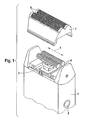
- the in Fig. 1 shown dry shaver consists of a housing 1, which serves, inter alia, the inclusion of a drawing not shown electric motor and, where appropriate, also not graphically illustrated accumulators for energy storage and is provided with an on / off switch 2.
- a housing 1 which serves, inter alia, the inclusion of a drawing not shown electric motor and, where appropriate, also not graphically illustrated accumulators for energy storage and is provided with an on / off switch 2.
- an oscillating driven drive element 3 is led out of the housing 1.
- the lower blade 4 are locked by appropriate / suitable per se known coupling means with the drive element 3.
- the two lower blades 4 arranged parallel to one another can then be driven in an oscillating manner along their longitudinal extent, that is to say in accordance with the double arrow 5.
- the lower blades 4 are at least partially surrounded in each case by one of the two outer blades, which are each formed as a perforated foil 6. They are mounted in a removable frame 7, which is latched to the housing 1.
- the perforated foils 6 are perforated flat with passage openings which can be embodied as holes and / or slots and through which the hair to be shaved enters the shaving head during the shaving process. Due to the cutting edges formed on both the film passage holes and the lower blades 4 and the movement of the lower blades 4 relative to the hole foils 6, the hairs entering the shaving head are sheared between the respective shearing edges.
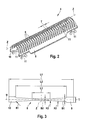
- FIG. 2 shown lower blade 4 has a plurality of U-shaped mutually parallel blades 8, which extend in the form of strips between the two edge regions 10 and 9.
- Each of the two edge regions 9 and 10 has at its front or rear end in each case a fastening portion 11 for connection to a carrier element not shown in detail, which ultimately serves to connect the lower blade 4 with the drive element 3 of the dry shaver.
- the longitudinal extent of each edge region 9 or 10 between its two attachment portions 11 corresponds to the direction of oscillation according to the double arrow 5.
- the blades 8 according to the embodiment shown here are perpendicular to the longitudinal extent of the edge regions 9, 10.
- the width of the blades 8 and the pitch T of Blades of the lower blade 4 are measured parallel to the longitudinal extent of the edge regions.
- the width of the strip-shaped blades 8 is not constant over the length L1, but tapers, starting from the edge portion 9 to the zenith Z of the bow to increase from there to the edge portion 10 out again. This becomes particularly apparent from the illustration Fig. 3 clear.
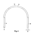
- Fig. 3 shows the development of a single blade 8, which is formed symmetrically both with respect to the center line M and with respect to the zenith Z.
- the edge regions 9, 10 are in Fig. 3 represented by the width of the pitch T, which is about 1 mm.
- the total length L1 of the blade 8 is approximately 11.5 mm.
- the entire tapered region of the blade 8 bounded on both sides by the approach of the inner radii R1 at the end regions 9, 10 extends over a length L2 of about 8.9 mm.
- the blade 8 tapers by means of a concave inner radius R1, which is about 0.2 mm, to the width B1, which is about 0.58 mm. This is followed by a convex outer radius R2 of about 33 mm. This gives the blade in this area a convex outer contour along its longitudinal extent. At the inside end of the radius R2, the blade merges with a concave inner radius R3 of about 3.5 mm into the parallel middle part. This part has a width B2 of 0.32 mm and a length L3 of about 3.1 mm.
- the notch effect is eliminated, which is due to the bending load due to the cutting forces occurring to blade fractures could occur in the connecting region between the edge regions 9, 10 and the blades 8 itself. Due to the outer radius R2, the stress distribution is evened out in the region of the greatest bending / torsional load and stress peaks are avoided. By the inner radius R3, the notch effect between R2 and the parallel middle part L3 is eliminated.
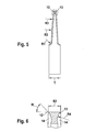
- Fig. 4 shows a view of a curved blade member 8, which was generated by corresponding U-shaped bending of an originally flat output lower blade 4.
- Der Blade 8 ist in der Figur 1 classroom.
- the flat starting lower blade 4 is produced in particular by an etching-technical process from a strip-shaped starting body made of metal, into which the slots lying between the individual blades 8 are etched. This starting body is then then bent in a U-shape, so that a lower blade, as it Fig. 2 shows, arises. Due to the etching technology production arises in the region of the two opposite cutting edges 12, 13 of each blade 8, an undercut, as in the FIGS. 5 and 6 is clearly shown. This undercut 14 is located after the U-shaped bending on the inside of the sheet. Again Fig. 4 can be removed, the material thickness of the starting sheet D is about 0.3 mm.
- Fig. 6 clearly shown undercut under each of the two cutting edges 12, 13 extends along a radius R4 of about 0.3 mm and generates at the cutting edges 12, 13 a cutting edge angle W of about 50 °.
Landscapes
- Engineering & Computer Science (AREA)
- Manufacturing & Machinery (AREA)
- Life Sciences & Earth Sciences (AREA)
- Forests & Forestry (AREA)
- Mechanical Engineering (AREA)
- Dry Shavers And Clippers (AREA)
Description
- Die Erfindung betrifft ein Untermesser für einen Trockenrasierapparat, gemäß dem Oberbegriff des Patentanspruches 1.
- Ein solches Untermesser ist beispielsweise aus der
DE-A 10 2005 009 264 A1 - Ein Untermesser ist auch aus der
US 7,022,195 B2 bekannt, wobei dieses Untermesser sich aus einer Vielzahl von streifenförmigen Klingenelementen zusammensetzt, die über eine konstante Breite oder über eine zur Mitte hin zunehmende Breite verfügen. - Derartige Untermesser befinden sich innerhalb des Scherkopfes eines Trockenrasierapparates oszillierend angetrieben und angepreßt an die Lochfolie und sind während des Rasiervorganges einer komplexen Belastung ausgesetzt.
- So werden sie einerseits durch den Anpreßdruck beaufschlagt, mit welchem der Benutzer den Rasierapparat gegen die Haut preßt, wodurch die streifenförmigen Klingen einer Biegebelastung um eine Achse ausgesetzt sind, die der Breitenerstreckung der Klingen entspricht. Während des Abscherens eines Haares tritt zusätzlich noch eine mechanische Belastung durch die Schnittkräfte auf, die sich im Zenit als Biegebelastung darstellt und nach außen hin zu einer komplexen Belastung aus zweiachsiger Biegung und Torsion wird. Eine weitere Belastung entsteht durch die Reibkraft zwischen der Lochfolie und dem Untermesser selbst.
- Die Untermesserkonstruktionen gemäß dem bekannten Typ weisen den Nachteil auf, daß sie sehr hohe Reibleistungen durch viskose Reibung zwischen Lochfolie und den beteiligten Reibflächen des Untermessers generieren. Dies führt zu einem hohen Energieverbrauch und darüber hinaus zu einer für den Benutzer unangenehmen Erhitzung der Scherteile sowie zu einem vorzeitigen Verschleiß. Aufgrund der ungleichförmigen mechanischen Spannungsverteilung über den Verlauf der einzelnen Klingen beulen sich diese bedingt durch die Kräfte, welche beim Anpressen des Scherkopfes an die Haut des Benutzers auftreten, ungleichmäßig über die Klingenlänge aus. Dies führt zu partiellem Verlust der direkten Anlage zwischen Untermesser und Lochfolie, wodurch in die Lochfolie bereits eingefädelte Haare nicht geschnitten, sondern lediglich eingezogen werden, was zu einem schmerzhaften Anreißen des Haares aus der Haut führen kann. Außerdem kann durch das ungleichmäßige Ausbeulen der Klingen die Lochfolie beschädigt werden.
- Es ist daher die Aufgabe der Erfindung, ein Untermesser der genannten Art auf kostengünstige Weise in Bezug auf seine Leistungsfähigkeit und Standfestigkeit zu verbessern. Diese Aufgabe wird erfindungsgemäß durch die kennzeichnenden Merkmale des Anspruches 1 gelöst.
- Durch die erfindungsgemäße Lösung wird eine gleichmäßige Materialbelastung über den gesamten Verlauf der einzelnen Klingen erzielt, wodurch die permanente gleichmäßige Anlage zwischen der Lochfolie und dem Untermesser auch unter starken Belastungen sichergestellt ist. Auch wird dadurch ermöglicht, daß im eigentlichen Schneidbereich die Klingen ohne Stabilitätsverlust schmal gehalten werden können, wodurch sich die viskose Reibung zwischen Lochfolie und Untermesser verringern läßt. Dadurch wird auch das eingesetzte Material besser ausgenutzt.
- Die Erfindung sieht dabei vor, daß die Verjüngung der Streifenbreite der Klingen stufenlos erfolgt, was eine gleichmäßige Belastungsverteilung entlang der Klinge fördert. Insbesondere ist die Verjüngung der Streifenbreite vorzugsweise bogenförmig ausgeführt.
- Erfolgt die Verjüngung der Streifenbreite der Klingen in Form mindestens zweier Übergangsradien, so läßt sich die Sicherheit gegen ein Brechen der Klingen im Bereich des Überganges zwischen den Randbereichen und der Klinge selbst verringern. Durch die entsprechende Ausgestaltung der Übergangsradien läßt sich nämlich die Wirkung der Kerbe in diesem Übergangsbereich nahezu eliminieren.
- Die Klingen werden bevorzugt symmetrisch zur Mittellinie der Streifen ausgebildet und weisen zur Reduzierung der beim Rasieren auftretenden Schneidkräfte vorzugsweise spitzwinkelige Schneidkanten auf.
- Weitere Ziele, Merkmale, Vorteile und Anwendungsmöglichkeiten der vorliegenden Erfindung ergeben sich aus der nachfolgenden Beschreibung eines Ausführungsbeispiels. Hierzu zeigt:
- Fig. 1
- den prinzipiellen Aufbau des Schersystems eines Trockenrasierapparates,
- Fig. 2
- die perspektivische Darstellung eines erfindungsgemäßen Untermessers,
- Fig. 3
- die Abwicklung einer einzigen Klinge gemäß des erfindungsgemäßen Untermessers,
- Fig. 4
- die Vorderansicht auf ein einzelnes Klingenelement,
- Fig. 5
- den Schnitt durch ein solches Klingenelement und
- Fig. 6
- eine vergrößerte Detailansicht aus
Fig. 5 . - Der in
Fig. 1 dargestellte Trockenrasierapparat besteht aus einem Gehäuse 1, das unter anderem der Aufnahme eines zeichnerisch nicht dargestellten Elektromotors und gegebenenfalls von ebenfalls zeichnerisch nicht dargestellten Akkumulatoren zur Energiespeicherung dient und mit einem Ein-/Aus-Schalter 2 versehen ist. An der oberen Stirnseite des Trockenrasierapparates ist ein oszillierend angetriebenes Antriebselement 3 aus dem Gehäuse 1 herausgeführt. Die Untermesser 4 sind über entsprechende/geeignete an sich bekannte Kupplungsmittel mit dem Antriebselement 3 verrastet. Hierdurch können dann die beiden parallel zueinander angeordneten Untermesser 4 in oszillierender Weise entlang deren Längserstreckung, also entsprechend dem Doppelpfeil 5 angetrieben werden. - Die Untermesser 4 sind zumindest teilweise jeweils von einem der beiden Obermesser umgeben, welche jeweils als Lochfolie 6 ausgebildet sind. Sie sind in einem Wechselrahmen 7 befestigt, welcher mit dem Gehäuse 1 verrastbar ist. Die Lochfolien 6 sind flächig mit Durchgangsöffnungen perforiert, die als Löcher und/oder Schlitze ausgeführt sein können und durch welche während des Rasiervorganges die zu rasierenden Haare in den Scherkopf eintreten. Aufgrund der Schneidkanten, die sowohl an den Foliendurchgangslöchern als auch an den Untermessern 4 ausgebildet sind und der Bewegung der Untermesser 4 relativ zu den Lochfolien 6 werden die in den Scherkopf eingetretenen Haare zwischen den entsprechenden Scherkanten abgeschert.
- Das in
Fig. 2 dargestellte erfindungsgemäße Untermesser 4 weist eine Vielzahl von U-förmigen parallel zueinander verlaufenden Klingen 8 auf, die in Form von Streifen zwischen den beiden Randbereichen 10 und 9 verlaufen. Jeder der beiden Randbereiche 9 und 10 weist an seinem vorderen bzw. hinteren Ende jeweils einen Befestigungsabschnitt 11 zur Verbindung mit einem zeichnerisch nicht näher dargestellten Trägerelement auf, welches letztendlich der Verbindung der Untermesser 4 mit dem Antriebselement 3 des Trockenrasierapparates dient. Die Längserstreckung eines jeden Randbereiches 9 bzw. 10 zwischen seinen beiden Befestigungsabschnitten 11 entspricht der Oszillationsrichtung gemäß dem Doppelpfeil 5. Die Klingen 8 verlaufen gemäß dem hier dargestellten Ausführungsbeispiel senkrecht zur Längserstreckung der Randbereiche 9, 10. Die Breite der Klingen 8 sowie die Teilung T der Klingen des Untermessers 4 werden parallel zur Längserstreckung der Randbereiche gemessen. - Wie bereits in
Fig. 2 zu erkennen und inFig. 3 noch näher dargestellt, ist die Breite der streifenförmigen Klingen 8 nicht konstant über deren Länge L1, sondern verjüngt sich, beginnend vom Randabschnitt 9 zum Zenit Z des Bogens hin, um von dort aus zum Randbereich 10 hin wieder zuzunehmen. Dies wird besonders aus der Darstellung gemäßFig. 3 deutlich. -
Fig. 3 zeigt die Abwicklung einer einzelnen Klinge 8, welche sowohl bezüglich der Mittellinie M als auch bezüglich des Zenits Z symmetrisch ausgebildet ist. Die Randbereiche 9, 10 sind inFig. 3 mit der Breite der Teilung T dargestellt, die etwa 1 mm beträgt. - Die Gesamtlänge L1 der Klinge 8 beträgt in etwa 11,5 mm. Der gesamte verjüngte Bereich der Klinge 8 beidseitig jeweils begrenzt durch den Ansatz der Innenradien R1 an den Endbereichen 9, 10 verläuft über eine Länge L2 von etwa 8,9 mm.
- Ausgehend von den Randbereichen 9, 10 verjüngt sich die Klinge 8 mittels eines konkaven Innenradius R1, der etwa 0,2 mm beträgt, auf die Breite B1, welche etwa 0,58 mm beträgt. Daran schließt sich ein konvexer Außenradius R2 von etwa 33 mm an. Dadurch erhält die Klinge in diesem Bereich eine konvexe Außenkontur entlang ihrer Längserstreckung. Am innenseitigen Ende des Radius R2 geht die Klinge mit einem konkaven Innenradius R3 von etwa 3,5 mm in den parallelen mittleren Teil über. Dieser Teil hat eine Breite B2 von 0,32 mm und eine Länge L3 von etwa 3,1 mm.
- Durch die Verjüngung der Klingenbreite mittels des Radius R1 wird die Kerbwirkung eliminiert, welche durch die Biegebelastung aufgrund der auftretenden Schnittkräfte zu Klingenbrüchen im Verbindungsbereich zwischen den Randbereichen 9, 10 und den Klingen 8 selbst auftreten könnten. Durch den Außenradius R2 wird im Bereich der größten Biege-Torsions-Belastung die Spannungsverteilung vergleichmäßigt und Spannungsspitzen vermieden. Durch den Innenradius R3 wird die Kerbwirkung zwischen R2 und dem parallelen mittleren Teil L3 eliminiert.
- Die Querschnittsreduktion der Klingen 8, beginnend von den Randbereichen 9, 10 bis hin zur Zenitachse Z verläuft in etwa gemäß der Abnahme der Biege- und Torsionsmomente, die aus den Schnittkräften und den Reibungskräften resultieren, so daß sich insgesamt eine sehr homogene Spannungsverteilung entlang der Klingenlänge (bzw. im U-förmig gebogenen Endzustand entlang der Klingenhöhe) ergibt. Dies begünstigt eine optimale Materialausnutzung und verhindert unregelmäßige Deformationen.
-
Fig. 4 zeigt eine Ansicht eines gebogenen Klingenelementes 8, welches durch entsprechendes U-förmiges Verbiegen eines ursprünglich ebenen Ausgangsuntermessers 4 erzeugt wurde. Das ebene Ausgangsuntermesser 4 wiederum wird insbesondere durch ein ätztechnisches Verfahren aus einem streifenförmigen Ausgangskörper aus Metall hergestellt, in den die zwischen den einzelnen Klingen 8 liegenden Schlitze eingeätzt werden. Dieser Ausgangskörper wird dann anschließend U-förmig gebogen, so daß ein Untermesser, wie esFig. 2 zeigt, entsteht. Bedingt durch die Ätztechnische Herstellung entsteht im Bereich der beiden gegenüberliegenden Schneidkanten 12, 13 einer jeden Klinge 8 ein Hinterschnitt, wie er in denFiguren 5 und 6 deutlich dargestellt ist. Dieser Hinterschnitt 14 liegt nach dem U-förmigen Verbiegen auf der Innenseite des Bogens. Wie derFig. 4 entnehmbar ist, beträgt die Materialstärke des Ausgangsbleches D etwa 0,3 mm. - Der in
Fig. 6 deutlich gezeigte Hinterschnitt unter jeder der beiden Schneidkanten 12, 13 verläuft entlang eines Radius R4 von etwa 0,3 mm und erzeugt an den Schneidkanten 12, 13 einen Schneidkantenwinkel W von etwa 50°.
Claims (3)
- Untermesser (4) für einen Trockenrasierapparat, wobei das Untermesser (4) mehrere voneinander beabstandete in Form von Streifen zwischen zwei Randbereichen (9, 10) Schneidkanten (12, 13) aufweisende Klingen (8) besitzt und im Querschnitt im wesentlichen U-förmig ausgebildet ist, und sich die Breite des Streifens von den beiden Randbereichen (9, 10) zur Mitte (Z) hin monoton verjüngt, wobei die Verjüngung der Streifenbreite stufenlos erfolgt, wobei die Klingen innerhalb des verjüngten Bereiches (22) einen parallelen mittleren Teil (23) aufweisen, dadurch gekennzeichnet, daß sich die Klingen von den Randbereichen (9, 10) zur Mitte (Z) hin jeweils durch zwei konkave Innenradien (R1, R3) verjüngen, zwischen welchen ein konvexer Außenradius (R2) vorgesehen ist.
- Untermesser nach Anspruch 1, dadurch gekennzeichnet, daß die Klingen (8) symmetrisch zur Mittellinie (M) ausgebildet sind.
- Untermesser nach Anspruch 1, dadurch gekennzeichnet, daß die Schneidkanten (12, 13) der Klingen (8) spitzwinklige Schneidkantenwinkel (W) aufweisen.
Applications Claiming Priority (2)
| Application Number | Priority Date | Filing Date | Title |
|---|---|---|---|
| DE102008027224A DE102008027224A1 (de) | 2008-06-06 | 2008-06-06 | Untermesser für den Scherkopf eines Trockenrasierapparates |
| PCT/EP2009/003600 WO2009146798A1 (de) | 2008-06-06 | 2009-05-20 | Untermesser für den scherkopf eines trockenrasierapparates |
Publications (2)
| Publication Number | Publication Date |
|---|---|
| EP2303524A1 EP2303524A1 (de) | 2011-04-06 |
| EP2303524B1 true EP2303524B1 (de) | 2013-09-11 |
Family
ID=40957941
Family Applications (1)
| Application Number | Title | Priority Date | Filing Date |
|---|---|---|---|
| EP09757181.4A Active EP2303524B1 (de) | 2008-06-06 | 2009-05-20 | Untermesser für den scherkopf eines trockenrasierapparates |
Country Status (6)
| Country | Link |
|---|---|
| US (1) | US8732961B2 (de) |
| EP (1) | EP2303524B1 (de) |
| JP (1) | JP5373068B2 (de) |
| CN (1) | CN102056716B (de) |
| DE (1) | DE102008027224A1 (de) |
| WO (1) | WO2009146798A1 (de) |
Families Citing this family (5)
| Publication number | Priority date | Publication date | Assignee | Title |
|---|---|---|---|---|
| DE102005036383A1 (de) * | 2005-07-29 | 2007-02-01 | Braun Gmbh | Scherkopf für einen elektrischen Rasierapparat |
| DE102008027224A1 (de) | 2008-06-06 | 2009-12-10 | Braun Gmbh | Untermesser für den Scherkopf eines Trockenrasierapparates |
| PL3131715T3 (pl) | 2014-04-18 | 2018-08-31 | Koninklijke Philips N.V. | Zestaw ostrzy, urządzenie do cięcia włosów, oraz związany z tym sposób wytwarzania |
| WO2016001019A1 (en) | 2014-07-04 | 2016-01-07 | Koninklijke Philips N.V. | Blade set, hair cutting appliance, and related manufacturing method |
| IT201900011250A1 (it) * | 2019-07-09 | 2021-01-09 | Gamma Piu S R L | Tagliacapelli elettrico |
Family Cites Families (17)
| Publication number | Priority date | Publication date | Assignee | Title |
|---|---|---|---|---|
| US2144525A (en) * | 1936-12-19 | 1939-01-17 | American Safety Razor Corp | Process of making dry shaver parts |
| US2223156A (en) * | 1937-12-07 | 1940-11-26 | Remington Rand Inc | Electric dry shaver |
| US2307471A (en) * | 1938-09-21 | 1943-01-05 | Remington Rand Inc | Shaving implement |
| US2325606A (en) * | 1940-07-26 | 1943-08-03 | Gillette Safety Rasor Company | Shaving implement |
| US2325605A (en) * | 1941-06-14 | 1943-08-03 | Nordberg Manufacturing Co | Impact member for impact crushers and securing means therefor |
| JP3237868B2 (ja) * | 1991-07-15 | 2001-12-10 | 松下電工株式会社 | 往復式電気かみそりの内刃の製法 |
| DE4423503C1 (de) * | 1994-07-05 | 1995-04-20 | Braun Ag | Untermesser für einen Trockenrasierapparat |
| KR100447912B1 (ko) * | 1996-04-26 | 2004-11-03 | 산요덴키가부시키가이샤 | 전기면도기와외부날의제조방법 |
| GB9614160D0 (en) * | 1996-07-05 | 1996-09-04 | Gillette Co | Dry shaving apparatus |
| WO2003022535A1 (fr) | 2001-09-10 | 2003-03-20 | Matsushita Electric Works, Ltd. | Prodede de fabrication de lame interieure de rasoir electrique |
| JP2005198795A (ja) | 2004-01-15 | 2005-07-28 | Izumi Products Co | 往復式電気かみそりの内刃製造方法および内刃 |
| JP2006042899A (ja) * | 2004-07-30 | 2006-02-16 | Matsushita Electric Works Ltd | 往復式電気かみそりの内刃 |
| KR200391316Y1 (ko) | 2005-01-28 | 2005-08-02 | 오태준 | 전기면도기의 절삭날 어셈블리 |
| DE102005036383A1 (de) * | 2005-07-29 | 2007-02-01 | Braun Gmbh | Scherkopf für einen elektrischen Rasierapparat |
| JP4963020B2 (ja) * | 2005-08-23 | 2012-06-27 | 株式会社泉精器製作所 | 往復式電気かみそりの内刃 |
| DE102006023774A1 (de) * | 2006-05-20 | 2007-11-22 | Braun Gmbh | Untermesser für einen Trockenrasiererscherkopf |
| DE102008027224A1 (de) | 2008-06-06 | 2009-12-10 | Braun Gmbh | Untermesser für den Scherkopf eines Trockenrasierapparates |
-
2008
- 2008-06-06 DE DE102008027224A patent/DE102008027224A1/de not_active Ceased
-
2009
- 2009-05-20 EP EP09757181.4A patent/EP2303524B1/de active Active
- 2009-05-20 JP JP2011511998A patent/JP5373068B2/ja active Active
- 2009-05-20 CN CN200980121069.7A patent/CN102056716B/zh active Active
- 2009-05-20 WO PCT/EP2009/003600 patent/WO2009146798A1/de active Application Filing
-
2010
- 2010-12-03 US US12/959,683 patent/US8732961B2/en active Active
Also Published As
| Publication number | Publication date |
|---|---|
| JP2011521750A (ja) | 2011-07-28 |
| DE102008027224A1 (de) | 2009-12-10 |
| EP2303524A1 (de) | 2011-04-06 |
| US8732961B2 (en) | 2014-05-27 |
| CN102056716B (zh) | 2016-10-19 |
| US20110067244A1 (en) | 2011-03-24 |
| WO2009146798A1 (de) | 2009-12-10 |
| CN102056716A (zh) | 2011-05-11 |
| JP5373068B2 (ja) | 2013-12-18 |
Similar Documents
| Publication | Publication Date | Title |
|---|---|---|
| EP2346651B1 (de) | Scherkopf für einen rasierapparat | |
| EP2303524B1 (de) | Untermesser für den scherkopf eines trockenrasierapparates | |
| DE3905788C2 (de) | Schneidwerkzeug zum Einschneiden von Rohren, um deren Biegung zu erleichtern | |
| EP1497082B1 (de) | Scherkopf für ein haarschneidegerät | |
| EP2146827A1 (de) | Schneideinrichtung zum schneiden von haaren | |
| EP2035194B1 (de) | Schereinheit für einen trockenrasierer | |
| EP1257391B1 (de) | Schneidmesser | |
| DE3036453A1 (de) | Scherkopf eines trockenrasiergeraetes | |
| DE102009035232B4 (de) | Schneidsatz für Haarschneidemaschinen | |
| EP2714313A1 (de) | Schermesser mit messereinsatz | |
| DE2836959C2 (de) | Langhaarscherteil, für Trockenrasierapparate | |
| WO2018077418A1 (de) | Schermesser und schneidgerät | |
| EP1910042B1 (de) | Scherkopf für einen elektrischen rasierapparat | |
| EP2110194A2 (de) | Sägeblatt und Handsäge | |
| EP1370397B1 (de) | Schersystem für einen trockenrasierer | |
| WO2018077419A1 (de) | Schermesser für ein schneidgerät | |
| EP2021153B1 (de) | Untermesser für einen trockenrasiererscherkopf | |
| EP1281359B1 (de) | Chirurgisches Messer | |
| DE2532725C2 (de) | Elektrisches Trockenrasiergerät | |
| CH273318A (de) | Mehrteiliges Spaltkeilgerät. | |
| EP3581349B1 (de) | Verbandsstoffschere | |
| EP0994212B1 (de) | Scherwendel | |
| DE3612717C1 (en) | Device for arranging transverse deformations on the insides of extruded light-metal hollow profiles | |
| EP0258675A2 (de) | Bandstahlstanzwerkzeug | |
| DE2254647B2 (de) | Saegezahnglied fuer eine saegekette |
Legal Events
| Date | Code | Title | Description |
|---|---|---|---|
| PUAI | Public reference made under article 153(3) epc to a published international application that has entered the european phase |
Free format text: ORIGINAL CODE: 0009012 |
|
| 17P | Request for examination filed |
Effective date: 20101118 |
|
| AK | Designated contracting states |
Kind code of ref document: A1 Designated state(s): AT BE BG CH CY CZ DE DK EE ES FI FR GB GR HR HU IE IS IT LI LT LU LV MC MK MT NL NO PL PT RO SE SI SK TR |
|
| AX | Request for extension of the european patent |
Extension state: AL BA RS |
|
| DAX | Request for extension of the european patent (deleted) | ||
| 17Q | First examination report despatched |
Effective date: 20120403 |
|
| GRAP | Despatch of communication of intention to grant a patent |
Free format text: ORIGINAL CODE: EPIDOSNIGR1 |
|
| INTG | Intention to grant announced |
Effective date: 20130415 |
|
| RIN1 | Information on inventor provided before grant (corrected) |
Inventor name: KRAUSS, JOACHIM Inventor name: JUNK, PETER Inventor name: ODEMER, MICHAEL Inventor name: POHL, THORSTEN Inventor name: ZEGULA, CHRISTOPH Inventor name: SCHWARZ, TOBIAS Inventor name: WOLF, JUERGEN Inventor name: HARTMANN, ANDREAS Inventor name: VERSTEGE, THOMAS Inventor name: SABISCH, MARKUS Inventor name: EICHHORN, REINHOLD Inventor name: PETER, ANDREAS |
|
| GRAS | Grant fee paid |
Free format text: ORIGINAL CODE: EPIDOSNIGR3 |
|
| GRAA | (expected) grant |
Free format text: ORIGINAL CODE: 0009210 |
|
| AK | Designated contracting states |
Kind code of ref document: B1 Designated state(s): AT BE BG CH CY CZ DE DK EE ES FI FR GB GR HR HU IE IS IT LI LT LU LV MC MK MT NL NO PL PT RO SE SI SK TR |
|
| REG | Reference to a national code |
Ref country code: GB Ref legal event code: FG4D Free format text: NOT ENGLISH |
|
| REG | Reference to a national code |
Ref country code: CH Ref legal event code: NV Representative=s name: BOHEST AG, CH Ref country code: CH Ref legal event code: EP |
|
| REG | Reference to a national code |
Ref country code: AT Ref legal event code: REF Ref document number: 631353 Country of ref document: AT Kind code of ref document: T Effective date: 20130915 |
|
| REG | Reference to a national code |
Ref country code: IE Ref legal event code: FG4D Free format text: LANGUAGE OF EP DOCUMENT: GERMAN |
|
| REG | Reference to a national code |
Ref country code: DE Ref legal event code: R096 Ref document number: 502009007992 Country of ref document: DE Effective date: 20131107 |
|
| REG | Reference to a national code |
Ref country code: NL Ref legal event code: T3 |
|
| PG25 | Lapsed in a contracting state [announced via postgrant information from national office to epo] |
Ref country code: LT Free format text: LAPSE BECAUSE OF FAILURE TO SUBMIT A TRANSLATION OF THE DESCRIPTION OR TO PAY THE FEE WITHIN THE PRESCRIBED TIME-LIMIT Effective date: 20130911 Ref country code: HR Free format text: LAPSE BECAUSE OF FAILURE TO SUBMIT A TRANSLATION OF THE DESCRIPTION OR TO PAY THE FEE WITHIN THE PRESCRIBED TIME-LIMIT Effective date: 20130911 Ref country code: CY Free format text: LAPSE BECAUSE OF FAILURE TO SUBMIT A TRANSLATION OF THE DESCRIPTION OR TO PAY THE FEE WITHIN THE PRESCRIBED TIME-LIMIT Effective date: 20130710 Ref country code: SE Free format text: LAPSE BECAUSE OF FAILURE TO SUBMIT A TRANSLATION OF THE DESCRIPTION OR TO PAY THE FEE WITHIN THE PRESCRIBED TIME-LIMIT Effective date: 20130911 Ref country code: NO Free format text: LAPSE BECAUSE OF FAILURE TO SUBMIT A TRANSLATION OF THE DESCRIPTION OR TO PAY THE FEE WITHIN THE PRESCRIBED TIME-LIMIT Effective date: 20131211 |
|
| REG | Reference to a national code |
Ref country code: LT Ref legal event code: MG4D |
|
| PG25 | Lapsed in a contracting state [announced via postgrant information from national office to epo] |
Ref country code: LV Free format text: LAPSE BECAUSE OF FAILURE TO SUBMIT A TRANSLATION OF THE DESCRIPTION OR TO PAY THE FEE WITHIN THE PRESCRIBED TIME-LIMIT Effective date: 20130911 Ref country code: SI Free format text: LAPSE BECAUSE OF FAILURE TO SUBMIT A TRANSLATION OF THE DESCRIPTION OR TO PAY THE FEE WITHIN THE PRESCRIBED TIME-LIMIT Effective date: 20130911 Ref country code: FI Free format text: LAPSE BECAUSE OF FAILURE TO SUBMIT A TRANSLATION OF THE DESCRIPTION OR TO PAY THE FEE WITHIN THE PRESCRIBED TIME-LIMIT Effective date: 20130911 Ref country code: GR Free format text: LAPSE BECAUSE OF FAILURE TO SUBMIT A TRANSLATION OF THE DESCRIPTION OR TO PAY THE FEE WITHIN THE PRESCRIBED TIME-LIMIT Effective date: 20131212 |
|
| PG25 | Lapsed in a contracting state [announced via postgrant information from national office to epo] |
Ref country code: CY Free format text: LAPSE BECAUSE OF FAILURE TO SUBMIT A TRANSLATION OF THE DESCRIPTION OR TO PAY THE FEE WITHIN THE PRESCRIBED TIME-LIMIT Effective date: 20130911 |
|
| PG25 | Lapsed in a contracting state [announced via postgrant information from national office to epo] |
Ref country code: RO Free format text: LAPSE BECAUSE OF FAILURE TO SUBMIT A TRANSLATION OF THE DESCRIPTION OR TO PAY THE FEE WITHIN THE PRESCRIBED TIME-LIMIT Effective date: 20130911 Ref country code: SK Free format text: LAPSE BECAUSE OF FAILURE TO SUBMIT A TRANSLATION OF THE DESCRIPTION OR TO PAY THE FEE WITHIN THE PRESCRIBED TIME-LIMIT Effective date: 20130911 Ref country code: CZ Free format text: LAPSE BECAUSE OF FAILURE TO SUBMIT A TRANSLATION OF THE DESCRIPTION OR TO PAY THE FEE WITHIN THE PRESCRIBED TIME-LIMIT Effective date: 20130911 Ref country code: EE Free format text: LAPSE BECAUSE OF FAILURE TO SUBMIT A TRANSLATION OF THE DESCRIPTION OR TO PAY THE FEE WITHIN THE PRESCRIBED TIME-LIMIT Effective date: 20130911 Ref country code: IS Free format text: LAPSE BECAUSE OF FAILURE TO SUBMIT A TRANSLATION OF THE DESCRIPTION OR TO PAY THE FEE WITHIN THE PRESCRIBED TIME-LIMIT Effective date: 20140111 |
|
| PG25 | Lapsed in a contracting state [announced via postgrant information from national office to epo] |
Ref country code: PL Free format text: LAPSE BECAUSE OF FAILURE TO SUBMIT A TRANSLATION OF THE DESCRIPTION OR TO PAY THE FEE WITHIN THE PRESCRIBED TIME-LIMIT Effective date: 20130911 Ref country code: ES Free format text: LAPSE BECAUSE OF FAILURE TO SUBMIT A TRANSLATION OF THE DESCRIPTION OR TO PAY THE FEE WITHIN THE PRESCRIBED TIME-LIMIT Effective date: 20130911 |
|
| REG | Reference to a national code |
Ref country code: DE Ref legal event code: R097 Ref document number: 502009007992 Country of ref document: DE |
|
| PG25 | Lapsed in a contracting state [announced via postgrant information from national office to epo] |
Ref country code: PT Free format text: LAPSE BECAUSE OF FAILURE TO SUBMIT A TRANSLATION OF THE DESCRIPTION OR TO PAY THE FEE WITHIN THE PRESCRIBED TIME-LIMIT Effective date: 20140113 |
|
| PLBE | No opposition filed within time limit |
Free format text: ORIGINAL CODE: 0009261 |
|
| STAA | Information on the status of an ep patent application or granted ep patent |
Free format text: STATUS: NO OPPOSITION FILED WITHIN TIME LIMIT |
|
| 26N | No opposition filed |
Effective date: 20140612 |
|
| PG25 | Lapsed in a contracting state [announced via postgrant information from national office to epo] |
Ref country code: IT Free format text: LAPSE BECAUSE OF FAILURE TO SUBMIT A TRANSLATION OF THE DESCRIPTION OR TO PAY THE FEE WITHIN THE PRESCRIBED TIME-LIMIT Effective date: 20130911 |
|
| REG | Reference to a national code |
Ref country code: DE Ref legal event code: R097 Ref document number: 502009007992 Country of ref document: DE Effective date: 20140612 |
|
| PG25 | Lapsed in a contracting state [announced via postgrant information from national office to epo] |
Ref country code: DK Free format text: LAPSE BECAUSE OF FAILURE TO SUBMIT A TRANSLATION OF THE DESCRIPTION OR TO PAY THE FEE WITHIN THE PRESCRIBED TIME-LIMIT Effective date: 20130911 |
|
| PG25 | Lapsed in a contracting state [announced via postgrant information from national office to epo] |
Ref country code: LU Free format text: LAPSE BECAUSE OF FAILURE TO SUBMIT A TRANSLATION OF THE DESCRIPTION OR TO PAY THE FEE WITHIN THE PRESCRIBED TIME-LIMIT Effective date: 20140520 |
|
| PG25 | Lapsed in a contracting state [announced via postgrant information from national office to epo] |
Ref country code: MC Free format text: LAPSE BECAUSE OF FAILURE TO SUBMIT A TRANSLATION OF THE DESCRIPTION OR TO PAY THE FEE WITHIN THE PRESCRIBED TIME-LIMIT Effective date: 20130911 |
|
| REG | Reference to a national code |
Ref country code: IE Ref legal event code: MM4A |
|
| PG25 | Lapsed in a contracting state [announced via postgrant information from national office to epo] |
Ref country code: IE Free format text: LAPSE BECAUSE OF NON-PAYMENT OF DUE FEES Effective date: 20140520 |
|
| PG25 | Lapsed in a contracting state [announced via postgrant information from national office to epo] |
Ref country code: MT Free format text: LAPSE BECAUSE OF FAILURE TO SUBMIT A TRANSLATION OF THE DESCRIPTION OR TO PAY THE FEE WITHIN THE PRESCRIBED TIME-LIMIT Effective date: 20130911 |
|
| REG | Reference to a national code |
Ref country code: FR Ref legal event code: PLFP Year of fee payment: 8 |
|
| PG25 | Lapsed in a contracting state [announced via postgrant information from national office to epo] |
Ref country code: BG Free format text: LAPSE BECAUSE OF FAILURE TO SUBMIT A TRANSLATION OF THE DESCRIPTION OR TO PAY THE FEE WITHIN THE PRESCRIBED TIME-LIMIT Effective date: 20130911 |
|
| PG25 | Lapsed in a contracting state [announced via postgrant information from national office to epo] |
Ref country code: BE Free format text: LAPSE BECAUSE OF FAILURE TO SUBMIT A TRANSLATION OF THE DESCRIPTION OR TO PAY THE FEE WITHIN THE PRESCRIBED TIME-LIMIT Effective date: 20140531 Ref country code: HU Free format text: LAPSE BECAUSE OF FAILURE TO SUBMIT A TRANSLATION OF THE DESCRIPTION OR TO PAY THE FEE WITHIN THE PRESCRIBED TIME-LIMIT; INVALID AB INITIO Effective date: 20090520 Ref country code: TR Free format text: LAPSE BECAUSE OF FAILURE TO SUBMIT A TRANSLATION OF THE DESCRIPTION OR TO PAY THE FEE WITHIN THE PRESCRIBED TIME-LIMIT Effective date: 20130911 |
|
| REG | Reference to a national code |
Ref country code: FR Ref legal event code: PLFP Year of fee payment: 9 |
|
| REG | Reference to a national code |
Ref country code: FR Ref legal event code: PLFP Year of fee payment: 10 |
|
| PG25 | Lapsed in a contracting state [announced via postgrant information from national office to epo] |
Ref country code: MK Free format text: LAPSE BECAUSE OF FAILURE TO SUBMIT A TRANSLATION OF THE DESCRIPTION OR TO PAY THE FEE WITHIN THE PRESCRIBED TIME-LIMIT Effective date: 20130911 |
|
| PGFP | Annual fee paid to national office [announced via postgrant information from national office to epo] |
Ref country code: CH Payment date: 20180516 Year of fee payment: 10 |
|
| PGFP | Annual fee paid to national office [announced via postgrant information from national office to epo] |
Ref country code: AT Payment date: 20180426 Year of fee payment: 10 |
|
| REG | Reference to a national code |
Ref country code: CH Ref legal event code: PL |
|
| REG | Reference to a national code |
Ref country code: AT Ref legal event code: MM01 Ref document number: 631353 Country of ref document: AT Kind code of ref document: T Effective date: 20190520 |
|
| PG25 | Lapsed in a contracting state [announced via postgrant information from national office to epo] |
Ref country code: CH Free format text: LAPSE BECAUSE OF NON-PAYMENT OF DUE FEES Effective date: 20190531 Ref country code: AT Free format text: LAPSE BECAUSE OF NON-PAYMENT OF DUE FEES Effective date: 20190520 Ref country code: LI Free format text: LAPSE BECAUSE OF NON-PAYMENT OF DUE FEES Effective date: 20190531 |
|
| REG | Reference to a national code |
Ref country code: FR Ref legal event code: PLFP Year of fee payment: 15 |
|
| PGFP | Annual fee paid to national office [announced via postgrant information from national office to epo] |
Ref country code: GB Payment date: 20230330 Year of fee payment: 15 |
|
| P01 | Opt-out of the competence of the unified patent court (upc) registered |
Effective date: 20230430 |
|
| PGFP | Annual fee paid to national office [announced via postgrant information from national office to epo] |
Ref country code: FR Payment date: 20230411 Year of fee payment: 15 Ref country code: DE Payment date: 20230331 Year of fee payment: 15 |
|
| PGFP | Annual fee paid to national office [announced via postgrant information from national office to epo] |
Ref country code: NL Payment date: 20240415 Year of fee payment: 16 |