EP2296520B2 - Dosiersystem für eine geschirrspülmaschine - Google Patents
Dosiersystem für eine geschirrspülmaschine Download PDFInfo
- Publication number
- EP2296520B2 EP2296520B2 EP09777177.8A EP09777177A EP2296520B2 EP 2296520 B2 EP2296520 B2 EP 2296520B2 EP 09777177 A EP09777177 A EP 09777177A EP 2296520 B2 EP2296520 B2 EP 2296520B2
- Authority
- EP
- European Patent Office
- Prior art keywords
- cartridge
- dosing
- dosing device
- chamber
- dishwasher
- Prior art date
- Legal status (The legal status is an assumption and is not a legal conclusion. Google has not performed a legal analysis and makes no representation as to the accuracy of the status listed.)
- Active
Links
Images


Classifications
-
- A—HUMAN NECESSITIES
- A47—FURNITURE; DOMESTIC ARTICLES OR APPLIANCES; COFFEE MILLS; SPICE MILLS; SUCTION CLEANERS IN GENERAL
- A47L—DOMESTIC WASHING OR CLEANING; SUCTION CLEANERS IN GENERAL
- A47L15/00—Washing or rinsing machines for crockery or tableware
- A47L15/42—Details
- A47L15/44—Devices for adding cleaning agents; Devices for dispensing cleaning agents, rinsing aids or deodorants
- A47L15/4463—Multi-dose dispensing arrangements
-
- A—HUMAN NECESSITIES
- A47—FURNITURE; DOMESTIC ARTICLES OR APPLIANCES; COFFEE MILLS; SPICE MILLS; SUCTION CLEANERS IN GENERAL
- A47L—DOMESTIC WASHING OR CLEANING; SUCTION CLEANERS IN GENERAL
- A47L15/00—Washing or rinsing machines for crockery or tableware
- A47L15/42—Details
- A47L15/44—Devices for adding cleaning agents; Devices for dispensing cleaning agents, rinsing aids or deodorants
-
- A—HUMAN NECESSITIES
- A47—FURNITURE; DOMESTIC ARTICLES OR APPLIANCES; COFFEE MILLS; SPICE MILLS; SUCTION CLEANERS IN GENERAL
- A47L—DOMESTIC WASHING OR CLEANING; SUCTION CLEANERS IN GENERAL
- A47L15/00—Washing or rinsing machines for crockery or tableware
- A47L15/0018—Controlling processes, i.e. processes to control the operation of the machine characterised by the purpose or target of the control
- A47L15/006—Controlling processes, i.e. processes to control the operation of the machine characterised by the purpose or target of the control using wireless communication between internal components of the machine
-
- A—HUMAN NECESSITIES
- A47—FURNITURE; DOMESTIC ARTICLES OR APPLIANCES; COFFEE MILLS; SPICE MILLS; SUCTION CLEANERS IN GENERAL
- A47L—DOMESTIC WASHING OR CLEANING; SUCTION CLEANERS IN GENERAL
- A47L15/00—Washing or rinsing machines for crockery or tableware
- A47L15/42—Details
- A47L15/44—Devices for adding cleaning agents; Devices for dispensing cleaning agents, rinsing aids or deodorants
- A47L15/4445—Detachable devices
- A47L15/4454—Detachable devices with automatic identification means, e.g. barcodes, RFID tags or magnetic strips
Definitions
- the invention relates to a dosing system, a combination dosing device for dispensing a plurality of preparations for use in dishwashers, and a dishwasher.
- Dishwashing detergents are available to the consumer in a large number of supply forms.
- automatic dishwashing detergents in particular are of great importance with the spread of household dishwashers.
- These machine dishwashing detergents are typically offered to the consumer in solid form, for example as a powder or as tablets, but increasingly also in liquid form.
- the main focus has been on the convenient dosing of cleaning agents and the simplification of the work steps required to carry out a cleaning process.
- one of the main goals of the manufacturers of mechanical cleaning agents is to improve the cleaning performance of these agents, with increased attention being paid recently to the cleaning performance in low-temperature cleaning cycles or in cleaning cycles with reduced water consumption.
- new ingredients such as more effective surfactants, polymers, enzymes or bleaches, were preferably added to the cleaning agents.
- new ingredients are only available to a limited extent and the amount of ingredients used per cleaning cycle cannot be increased to any desired extent for ecological and economic reasons, there are natural limits to this approach.
- WO 02/29150 A1 discloses a self-sufficient dosing device for a dishwasher that can be coupled to a cartridge.
- the metering device includes a sensor unit and a control unit.
- DE 10 2006 043916 A1 describes an actuator, a closure element, and a dosing chamber with an inlet opening and an outlet opening for a water-bearing household appliance.
- the object of the invention is to provide an improved dosing system according to claim 1, 2 or 3, a combination dosing device according to claim 4, and a dishwasher according to claim 5.
- the dosing system consists of the basic components of a cartridge and a dosing device that can be coupled to the cartridge, which in turn is formed from other assemblies such as component carriers, actuators, closure elements, sensors, energy sources and/or control units.
- the dosing system according to the invention is movable. Movable within the meaning of this application means that the dosing system is not permanently connected to a dishwasher, but can be removed from a dishwasher by the user or positioned in a dishwasher, ie can be handled independently
- the dosing device is not detachably connected to a dishwasher for the user and only the cartridge is movable.
- the dosing system can be formed from materials that are dimensionally stable up to a temperature of 120°C.
- the preparations to be dosed can have a pH of between 2 and 12, depending on the intended use, all components of the dosing system that come into contact with the preparations should have an appropriate acid and/or alkali resistance. Furthermore, these components should be largely chemically inert, for example to nonionic surfactants, enzymes and/or fragrances, by selecting a suitable material.
- a cartridge in the context of this application is understood to mean a packaging means which is suitable for enclosing or holding together at least one free-flowing, pourable or spreadable preparation and which can be coupled to a dosing device for dispensing at least one preparation.
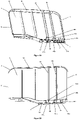
- the cartridge has a preferably dimensionally stable chamber for storing a preparation.
- a cartridge can also comprise a plurality of chambers which can be filled with compositions that differ from one another.
- the cartridge prefferably has at least one outlet opening which is arranged in such a way that the preparation can be released from the cartridge by gravity when the dosing device is in the position of use.
- no further means of conveyance are required for releasing preparation from the cartridge, as a result of which the structure of the dosing device can be kept simple and the production costs can be kept low.
- the use of funding, such as pumps, can be omitted, which can increase the service life of a battery or accumulators of the dosing device.
- At least one second chamber is provided for receiving at least one second free-flowing or spreadable preparation, the second chamber having at least one outlet opening which is arranged in such a way that the product is released from the second chamber by gravity when the dosing device is in the position of use can be effected.
- the arrangement of a second chamber is particularly advantageous when preparations are stored in the mutually separate chambers of the cartridge which are usually not storable together, such as bleaches and enzymes.
- one of the chambers can be designed to release volatile preparations, such as a fragrance, to the environment.
- the cartridge is designed in one piece.
- the cartridges can be formed cost-effectively in one production step, in particular by means of suitable blow molding processes.
- the chambers of a cartridge can be separated from one another, for example, by webs or material bridges that are formed during or after the blow molding process.
- the cartridge can also be formed in several pieces by components that are produced by injection molding and then joined together.
- the cartridge is formed in several pieces in such a way that at least one chamber, preferably all chambers, can be individually removed from the dosing device or inserted into the dosing device.
- at least one chamber preferably all chambers
- the cartridge is formed in several pieces in such a way that at least one chamber, preferably all chambers, can be individually removed from the dosing device or inserted into the dosing device.
- the individual chambers in such a way that the chambers can only be coupled to one another or to the dosing device in a specific location or position, thereby preventing a user from using a chamber in a position that is not intended for this purpose connects to the dosing device.
- the chamber walls can in particular be shaped in such a way that they can be connected to one another in a form-fitting manner. It is particularly advantageous, in the case of a cartridge formed from at least three chambers, to shape the cartridges in such a way that the chambers can only be positively connected to one another in a certain defined position.
- the chambers of a cartridge can be fixed to one another by suitable connection methods, so that a container unit is formed.
- the chambers can be fixed to one another in a detachable or non-detachable manner by means of a suitable positive, non-positive or material connection.
- the fixation can be done by one or more of the connection types from the group of snap-in connections, Velcro connections, press connections, fusion connections, adhesive connections, welded connections, soldered connections, screw connections, wedge connections, clamp connections or snap connections.
- the fixation can also be formed by a shrink tube (so-called sleeve), which is pulled over the whole or sections of the cartridge in a heated state and firmly encloses the chambers or the cartridge in the cooled state.
- the bottom of the chambers can be inclined in a funnel shape towards the discharge opening.
- the inner wall of a chamber can be designed by selecting a suitable material and/or surface design in such a way that a low level of material adhesion of the preparation to the inner chamber wall is achieved. This measure also allows the remaining emptying of a chamber to be further optimized.
- the cartridge can also be designed asymmetrically. It is particularly preferred to shape the asymmetry of the cartridge in such a way that the cartridge can only be coupled to the dosing device in a predefined position, which prevents incorrect operation by the user that would otherwise be possible.
- a dosing chamber can be in or on one chamber, in the flow direction of the preparation caused by gravity the outlet opening of a chamber.
- the amount of preparation that is to be released into the environment when the preparation is released from the chamber is determined by the dosing chamber. This is particularly advantageous when the closure element of the dosing device, which causes the preparation to be released from a chamber to the environment, can only be put into a release and a closed state without measuring or checking the amount released.
- the dosing chamber then ensures that a predefined amount of preparation is released without immediate feedback of the currently dispensed, outflowing amount of preparation.
- the dosing chambers can be formed in one piece or in several pieces. Furthermore, it is possible to design the dosing chambers to be permanently connected to the cartridge or to be detachable. With a dosing chamber that is detachably connected to the cartridge, it is possible in a simple manner to connect dosing chambers with dosing volumes that differ from one another to a cartridge or to exchange them, which means that the dosing volumes can be easily adapted to the preparation stored in a chamber and thus simple packaging of the cartridge for different preparations and their dosage is possible.
- one or more chambers have a liquid-tight sealable, preferably head-side, second chamber opening in addition to a preferably bottom-side outlet opening.
- This chamber opening makes it possible, for example, to refill the preparation stored in this chamber.
- ventilation options can be provided in particular in the head area of the cartridge in order to ensure pressure equalization between the inside of the cartridge chambers and the environment when the filling level of the chambers falls.
- These ventilation options can be designed, for example, as a valve, in particular a silicone valve, micro-openings in a chamber or cartridge wall, or the like.
- the cartridge chambers are not ventilated directly, but rather via the dosing device or no ventilation, e.g. when using flexible containers such as bags, this has the advantage that at elevated temperatures during a washing cycle of a dishwasher by heating the contents of the chamber, a pressure is built up, which presses the preparations to be dosed in the direction of the outlet openings, so that the cartridge can be easily emptied of residues. Furthermore, with such air-free packaging there is no risk of substances in the preparation oxidizing, which makes pouch packaging or bag-in-bottle packaging appear expedient, particularly for preparations which are sensitive to oxidation.
- the volume ratio formed from the construction volume of the dosing device and the filling volume of the cartridge is preferably ⁇ 1, particularly preferably ⁇ 0.1, particularly preferably ⁇ 0.05. In this way it is achieved that with a given overall construction volume of dosing device and cartridge, the majority of the construction volume is occupied by the cartridge and the preparation contained therein.
- the cartridge can assume any shape. It can, for example, be cube-like, spherical or plate-like.
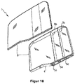
- the cartridge and the dosing device can in particular be designed with regard to their three-dimensional shape in such a way that they ensure the lowest possible loss of useful volume, in particular in a dishwasher.
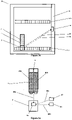
- the dosing device In order to use the dosing device in dishwashers, it is particularly advantageous to shape the device based on dishes to be cleaned in dishwashers. For example, this can be plate-shaped, approximately the dimensions of a plate. This allows the dosing device to be positioned in a space-saving manner, e.g. in the lower basket of the dishwasher. Furthermore, the correct positioning of the dosing unit is immediately intuitive to the user due to the plate-like shape.
- the dosing device and the cartridge When coupled to one another, the dosing device and the cartridge preferably have a height:width:depth ratio of between 5:5:1 and 50:50:1, particularly preferably approximately 10:10:1.
- the "slim" design of the dosing device and the cartridge makes it possible in particular to position the device in the lower cutlery basket of a dishwasher in the receptacles provided for plates. This has the advantage that the preparations dispensed from the dosing device get directly into the wash liquor and cannot adhere to other items to be washed.
- the dosing system is dimensioned such that the dosing system can only be positioned in the receptacles provided for this purpose of the lower basket is allowed.
- the width and the height of the dosing system can be selected in particular between 150 mm and 300 mm, particularly preferably between 175 mm and 250 mm.
- the dosing unit in the form of a cup or pot with a substantially circular or square base.
- the outlet openings of a cartridge are preferably arranged in a line, as a result of which a slim, plate-shaped design of the dosing device is made possible.
- the cartridge In order to provide an immediate visual fill level check, it is advantageous to form the cartridge, at least in sections, from a transparent material.
- a further possibility for reducing the influence of heat on a preparation in a chamber of the cartridge is to isolate the chamber by suitable measures, e.g. by using thermal insulation materials such as Styrofoam, which completely or partially enclose the chamber or the cartridge in a suitable manner.
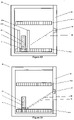
- a further measure for protecting heat-sensitive substances in a cartridge is, in the case of a plurality of chambers, their mutual arrangement.
- the chamber containing a heat-sensitive product is partially or completely enclosed by at least one other chamber filled with a product, with this product and this chamber acting as thermal insulation for the enclosed chamber in this configuration.
- a first chamber, which contains a heat-sensitive product is partially or completely surrounded by at least one other chamber filled with a product, so that the heat-sensitive product in the first chamber has a slower temperature rise when the environment heats up than the products in the surrounding chambers.
- the chambers can be arranged one around the other according to the Matryoshka principle, so that a multi-layer insulation layer is formed.
- At least one preparation which is stored in an enclosing chamber, has a thermal conductivity of between 0.01 and 5 W/m*K, preferably between 0.02 and 2 W/m*k, particularly preferably between 0.024 and 1 W/m*K.
- the cartridge is in particular designed to be dimensionally stable.
- the cartridge is also conceivable to design the cartridge as a flexible packaging material such as a tube.
- flexible containers such as bags, in particular if they are used in accordance with the "bag-in-bottle" principle in a substantially dimensionally stable receiving container.
- the use of flexible packaging eliminates the need to provide a ventilation system for pressure equalization--unlike in the case of the dimensionally stable cartridge configurations described at the outset.
- the cartridge has an RFID label that contains at least information about the content of the cartridge and that can be read by a sensor unit that can be provided in particular in the dosing device or dishwasher.
- This information can be used, for example, to select a dosing program stored in the control unit of the dosing device. This can ensure that a dosing program that is optimal for a specific preparation is always used. It can also be provided that in the absence of an RFID label or in the case of an RFID label with an incorrect or faulty identifier, no dosing takes place through the dosing device and instead an optical or acoustic signal is generated that alerts the user to the present error indicates.
- the cartridges can also have structural elements which interact with corresponding elements of the dispensing device according to the lock and key principle, so that, for example, only cartridges of a specific type can be coupled to the dispensing device. Furthermore, this configuration makes it possible for information about the cartridge coupled to the dosing device to be transmitted to the control unit of the dosing device, as a result of which the dosing device can be controlled in a way that is tailored to the content of the corresponding container.
- the cartridge is designed in particular to hold free-flowing cleaning agents.
- a cartridge particularly preferably has a plurality of chambers for the spatially separated reception of different preparations of a cleaning agent.
- Some possible combinations of filling the chambers with different preparations are listed below as an example - but not exhaustively: chamber 1 chamber 2 chamber 3 chamber 4 A Alkaline cleaning preparation Enzymatic cleaning preparation - - B Alkaline cleaning preparation Enzymatic cleaning preparation rinse aid - C Alkaline cleaning preparation Enzymatic cleaning preparation rinse aid perfume D Alkaline cleaning preparation Enzymatic cleaning preparation rinse aid disinfectant preparation E Alkaline cleaning preparation Enzymatic cleaning preparation rinse aid pre-treatment preparation
- all preparations are flowable, as this ensures that the preparations dissolve quickly in the washing liquor of the dishwasher, giving these preparations a rapid to immediate cleaning or rinsing effect, especially on the walls of the washing cabinet and / or a achieve light guide of the cartridge and/or the dosing device.
- the cartridge usually has a total filling volume of ⁇ 5000 ml, in particular ⁇ 1000 ml, preferably ⁇ 500 ml, particularly preferably ⁇ 250 ml, very particularly preferably ⁇ 50 ml.
- the chambers of a cartridge can have the same or different filling volumes.
- the ratio of the chamber volumes is preferably 5:1, in a configuration with three chambers it is preferably 4:1:1, these configurations being particularly suitable for use in dishwashers.
- the cartridge preferably has three chambers.
- one chamber contains an alkaline cleaning preparation
- another chamber contains an enzymatic preparation
- a third chamber contains a rinse aid, with the volume ratio of the chambers being approximately 4:1:1.
- the chamber containing the alkaline cleaning preparation preferably has the largest filling volume of the existing chambers.
- the chambers that store an enzymatic preparation or a rinse aid preferably have approximately the same filling volumes.
- the cartridge With a two- and/or three-chamber design of the cartridge, it is possible in particular to store a fragrance, disinfection and/or pretreatment preparation in a further chamber that is detachably arranged on the cartridge or on the dosing device.
- the cartridge comprises a cartridge base which, in the position of use, is directed downwards in the direction of gravity and on which at least one outlet opening arranged on the base in the direction of gravity is preferably provided for each chamber.
- the outlet openings arranged on the bottom are designed in particular in such a way that at least one, preferably all outlet openings can be connected in a communicating manner with the inlet openings of the dosing device, i.e. preparation can flow from the cartridge into the dosing device via the outlet openings, preferably under the effect of gravity.
- one or more chambers have an outlet opening that is not arranged on the bottom side in the direction of gravity. This is particularly advantageous if, for example, a fragrance is to be released into the surroundings of the cartridge.
- the cartridge is preferably formed from at least two elements which are materially connected to one another, with the connecting edge of the elements running on the cartridge base outside the outlet openings, ie the connecting edge does not intersect the outlet openings. This is particularly advantageous since this avoids problems with sealing when coupling to the dosing device in the area of the outlet openings, which occur in particular with the high thermal cycling stresses that usually occur in a dishwasher.
- the material connection can be produced, for example, by gluing, welding, soldering, pressing or vulcanizing.
- a metallic heating mirror which contains the contour of the interfaces to be connected, heats the interfaces and briefly puts them in the plastic state, so that after removing the heating mirror and assembling the parts, these plastic areas solidify again as a melt and form a solid one connect.
- individually injection-moulded parts for example, be connected to each other by means of laser welding.
- laser welding one of the two materials that is to be melted at the interface must carry an absorbent in order to absorb the energy content of the laser beam and convert it into heat, which then causes the corresponding material area to melt. This is typically achieved with color pigments that thermally interact with the laser beam directed into the material.
- boundary surfaces to be joined can also be covered if the material in front of them in the direction of incidence of the laser beam is transparent to the laser beam and has no absorption properties.
- the joining edge runs along the top, bottom and side faces of the cartridge.
- two cartridge elements can be produced, in particular by injection molding, with either both elements being trough-shaped or one element being trough-shaped and the second element being cover-like.
- At least one of the two cartridge elements can comprise at least one separating web which separates two adjacent chambers of the cartridge from one another when the elements are in the assembled state.
- one cartridge element is a cup-like container with at least one chamber and the second element is the cartridge base or head, which is connected to the cup-like container in a liquid-tight manner along the connecting edge.
- such a further chamber for receiving a preparation can be arranged on the cartridge and configured in such a way that volatile substances such as fragrances are released from the preparation into the environment of the chamber.
- the outlet openings of the cartridge are closed by closure means at least when the cartridge is in the filled, unopened state.
- the closure means can be designed in such a way that they allow the outlet opening to be opened once by destroying the closure means.
- closure means are, for example, sealing foils or closure caps.
- the outlet openings are each provided with a closure which allows preparation to flow out of the respective chambers when coupled to a dosing device and essentially prevents preparation from flowing out when the cartridge is uncoupled.
- a closure is designed as a slotted silicone valve.
- the ventilation openings of the cartridge are closed with a closure element before a first coupling with the dosing device.
- the closure element can in particular be a stopper or a cap which is opened, for example pierced, by the coupling process when it is first coupled to the dosing device.
- the cartridge elements forming the cartridge are preferably made of a plastic and can be molded in a common injection molding process, it being advantageous to mold a connecting web acting as a hinge between the two elements, so that after molding the two elements rest against one another by folding over and are connected in a materially bonded manner along the connecting edge.
- an energy source in particular a battery or accumulator, is arranged on or in the cartridge, preferably on or in the bottom of the cartridge. Furthermore, means for electrically coupling the energy source to the dosing device can be provided on the cartridge.
- the cartridge has at least one chamber for storing at least one free-flowing or pourable cleaning agent preparation for coupling to a dosing device that can be positioned inside a household appliance for dispensing at least one cleaning agent preparation, the cartridge being coupled to the dosing device state is protected against the entry of rinsing water into the chamber(s) and the cartridge comprises at least one discharge opening on the bottom in the direction of gravity for - in particular under the effect of gravity - dispensing of preparation from at least one chamber and at least one ventilation opening on the bottom in the direction of gravity for ventilation of at least one chamber, wherein the Ventilation opening is separated from the discharge opening and the ventilation opening communicating with at least one chamber of cartridge is connected.
- the cartridge comprises at least two chambers, very particularly preferably at least three chambers. It is advantageous here that a ventilation opening and a discharge opening are provided for each chamber.
- the bottom ventilation opening communicates with a ventilation channel whose end facing away from the ventilation opening opens out above the maximum fill level of the cartridge in the dispensing position of the cartridge coupled to the dosing device.
- the ventilation channel it is advantageous for the ventilation channel to be formed entirely or partially in or on the walls and/or webs of the cartridge.
- the ventilation channel can be formed integrally in or on the walls and/or webs of the cartridge.
- the ventilation duct can advantageously be formed by joining at least two elements forming the cartridge.
- a ventilation channel can be formed by joining a separating web of the cartridge, formed in the shell-shaped element, to two webs enclosing the separating web and arranged on the cartridge element.
- the ventilation duct is formed by cohesive joining, in particular by welding, of a separating web of the cartridge formed in the shell-shaped element with two webs enclosing the separating web and arranged on the cartridge element.
- the ventilation channel can also be used as a so-called Be trained dip tube.
- the filling level (F) of the cartridge in the unopened, filled state of the cartridge is at an inclination of up to 45 ° not present at the ventilation duct mouth (83).
- the ventilation channel mouth approximately in the middle on or in the chamber wall of the cartridge head.
- the viscosity of a free-flowing preparation and the ventilation channel are configured in such a way that the preparation is not drawn into the ventilation channel by capillary forces when the preparation is on the Ventilation duct mouth pending.
- the coupling of the cartridge to the dosing device should advantageously be designed in such a way that a mandrel is arranged on the dosing device, which is connected to the inlet opening of the dosing device and communicates with the connectable cartridge or cartridge chamber in such a way that when the ventilation opening of the cartridge or In the cartridge chamber with the dosing device, the mandrel displaces a volume ⁇ v in the ventilation duct, as a result of which a pressure ⁇ p is generated in the ventilation duct which is suitable for conveying the flowable preparation located in the ventilation duct into the chamber connected to the ventilation duct and storing the preparation.
- the ventilation opening of a chamber is connected in communication with the dosing device-side mandrel before the closed outlet opening of the corresponding chamber is opened, for example by communicating with the inlet opening of the dosing device.
- a ventilation chamber is arranged between the ventilation opening and the ventilation channel.
- the cartridge can be designed in such a way that it can be arranged detachably or permanently in or on the dosing device and/or a dishwasher.
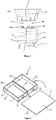
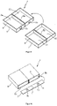
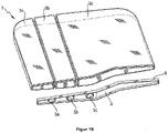
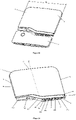
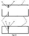
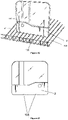
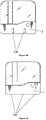
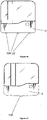
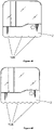
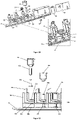
- the dosing device for dispensing at least one free-flowing cleaning agent preparation into the interior of a household appliance comprises a cartridge that can be coupled to the dosing device, the cartridge storing at least one free-flowing cleaning agent preparation and the cartridge having at least one outlet opening on the bottom in the direction of gravity, which coupled to the dosing device, is connected in a communicating manner to an inlet opening of the dosing device, with the dosing device and the cartridge having means which interact in such a way that a releasable latching between the dosing device and the cartridge can be produced, with the dosing device and the cartridge being rotated relative to one another in the latched state pivot at a pivot point (SP), and that the outlet port of the cartridge and the inlet port of the dosing console are configured such that, after the cartridge and D dispensing device are connected in a communicating manner by pivoting the cartridge into the coupling state between dispensing console and cartridge.
- SP pivot point
- outlet openings of the chambers and the inlet openings of the dosing device are arranged and configured in such a way that they are sequentially connected to one another by pivoting in the latched state into the coupling state of dosing device and cartridge.
- the dosing device and/or the cartridge can have means which cause the cartridge to be detachably fixed to the dosing device when the dosing device and cartridge are coupled.
- This can be realized, for example, by a collar running on the bottom side of the cartridge, which is set back slightly compared to a corresponding collar on the dosing device side, so that it is guided on the cartridge-side collar inside the collar on the dosing device side.
- the outlet openings of the chambers are arranged one behind the other in the pivoting direction. It is particularly preferred that the outlet openings of the chambers are arranged on a line (L) in the pivoting direction.
- outlet openings of the chambers have approximately the same distance from one another.
- the greatest distance between an outlet opening of a chamber and the pivot point (SP) of the cartridge corresponds to approximately 0.5 times the distance of the cartridge width (B).
- At least two chambers of the cartridge can have different volumes from one another.
- the chamber of the cartridge with the greatest volume is at the greatest distance from the pivot point (SP) of the cartridge 1.
- the ventilation opening of a chamber lies in front of an outlet opening of the chamber in the pivoting direction when the cartridge is coupled to the dosing device.
- the ratio of the depth (T) of the cartridge to the width (B) of the cartridge is preferably approximately 1:20.
- the ratio of the height (H) of the cartridge to the width (B) of the cartridge is preferably approximately 1:1.2.
- the ventilation opening of a chamber lies in front of an outlet opening of the chamber in the pivoting direction when the cartridge is coupled to the dosing device. This ensures that the ventilation opening of the cartridge is opened first before the outlet opening of the cartridge is opened when the cartridge is coupled to the dosing device.
- the cartridge for coupling to a dosing device for dispensing at least one cleaning agent preparation from the cartridge into the interior of a household appliance comprises a light guide arranged in or on the cartridge, into which a light signal from outside the cartridge can be coupled. It is particularly preferred to couple a light signal, which is emitted from the dosing device, into the cartridge.
- the light guide can be formed entirely or partially in or on the walls and/or webs of the cartridge.
- the light guide integrally in or on the walls and/or webs of the cartridge.
- the light guide preferably consists of a transparent plastic material. However, it is also possible to form the entire cartridge from a transparent material.
- the light guide is capable of guiding light in the visible range (380-780 nm). It is particularly preferable that the light guide is capable of conducting light in the near infrared range (780nm-3000nm). In particular, it is preferred that the light guide is capable of conducting light in the mid-infrared range (3.0 ⁇ m-50 ⁇ m).
- the light guide consists of a transparent plastic material with a high refractive index.
- the light guide is advantageously completely or partially enclosed, at least in sections, by a material with a lower optical refractive index.
- the material with the lower optical refractive index can be a preparation stored in a chamber of the cartridge.
- the refractive index of the light guide can be determined according to DIN EN ISO 489, for example.
- the refractive index of the preparation can be determined using an Abbe refractometer according to DIN 53491.
- the preparation that completely or partially encloses the light guide has a transmittance of 45%-95%, particularly preferably 60%-90%, very particularly preferably 75%-85%.
- the light guide preferably has a transmittance of >75%, very particularly preferably >85%.
- the transmittance can be determined according to DIN5036.
- the wavelength of the light that is sent through the light guide corresponds approximately to the wavelength of at least one preparation that encloses the light guide at least in sections, which is not absorbed by the preparation from the visible spectrum.
- the wavelength of the light that is transmitted through the light guide and the wavelength that is not absorbed by the preparation is between 600-800 nm.
- the light signal that can be coupled into the light guide is, in particular, a carrier of information, in particular, for example, with regard to the operating state of the dosing device and/or the filling level of the cartridge.
- the light guide is designed in such a way that the light signal that can be coupled into the light guide can also be coupled out of the light guide again.
- the light guide can be designed in such a way that the light signal can be coupled out at a point on the cartridge which is different from the point at which the light signal can be coupled into the cartridge.
- the coupling and decoupling of the light signal can be realized in particular on a prismatic edge of the cartridge.
- the distance between the light source arranged in the dosing device, in particular an LED, and the point at which the light is coupled into the cartridge when the cartridge and dosing device are coupled should be kept as small as possible.
- the light signal and the light guide are configured in such a way that a light signal visible to a user can be generated on and/or in the cartridge.
- the light guide can be severed at at least one point in the cartridge in such a way that the preparation can fill the point of separation.
- a fill level and/or inclination sensor can be implemented in a simple manner, with a light signal that passes through the separation point without preparation being different from the light signal that passes through the separation point that is completely or partially filled with preparation.
- control unit required for operation and at least one actuator are integrated in the dosing device.
- a sensor unit and/or an energy source is also preferably arranged on or in the dosing device.
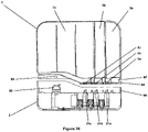
- the dosing device consists of a splash-proof housing that prevents the ingress of splashing water, such as can occur when used in a dishwasher, into the interior of the dosing device, in which at least the control unit, sensor unit and/or actuator are arranged.
- the dosing device is essentially watertight, ie the dosing device is functional even when it is completely surrounded by liquid.
- multi-component epoxy and acrylate casting compounds such as methacrylate esters, urethane-metha and cyanoacrylates or two-component materials with polyurethanes, silicones, epoxy resins can be used as casting materials.
- the material from which the dosing device is formed prevents or at least reduces the growth of a biofilm.
- additives such as biocides, for example, can be used for this purpose.
- areas of the dosing device that are at risk of microbial growth, in particular areas where rinsing water can accumulate to be partially equipped with a material that prevents or at least reduces the growth of a biofilm.
- correspondingly acting foils can also be used.
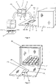
- the dosing device comprises at least one first interface, which interacts in or on a household appliance, in particular a corresponding interface configured in a dishwasher, in such a way that electrical energy and/or signals are transmitted from the household appliance to the dosing device and/or from the Dosing device is realized for household appliance.
- the interfaces are formed by plug connectors.
- the interfaces can be designed in such a way that wireless transmission of electrical energy and/or electrical and/or optical signals is effected.
- the interfaces provided for the transmission of electrical energy are inductive transmitters or receivers of electromagnetic waves.
- the interface of a dishwasher can be designed as a transmitter coil with an iron core operated with alternating current, and the interface of the dosing device can be designed as a receiver coil with an iron core.
- the transmission of electrical energy can also be provided by means of an interface which comprises an electrically operated light source on the household appliance side and a light sensor, for example a photodiode or a solar cell, on the dosing device side.
- a light sensor for example a photodiode or a solar cell
- the light emitted by the light source is converted by the light sensor into electrical energy, which in turn feeds, for example, an accumulator on the dosing device.
- an interface on the dosing device and the water-carrying device, such as a dishwasher for the transmission (i.e. sending and receiving) of electromagnetic and/or optical signals, which in particular contain operating status, measurement and/or control information of the dosing device and/or represent the water-carrying device such as a dishwasher.
- such an interface can be designed in such a way that wireless transmission of electrical energy and/or electromagnetic and/or optical signals is effected.
- At least one interface is configured to transmit and/or receive optical signals in the wavelength range between 600-800 nm. Since darkness usually prevails inside the washing compartment when a dishwasher is in operation, signals in the visible, optical range, for example in the form of signal pulses or flashes of light, can be emitted and/or detected by the dosing device. It has proven particularly advantageous to use wavelengths between 600-800 nm in the visible spectrum.
- the interface includes at least one LED.
- the interface particularly preferably comprises at least two LEDs. It is also possible according to a further preferred embodiment of the invention to provide at least two LEDs which emit light at different wavelengths. This makes it possible, for example, to define different signal bands on which information can be sent or received.
- At least one LED is an RGB LED whose wavelength can be adjusted.
- one LED can be used to define different signal bands that emit signals on different wavelengths. It is also conceivable, for example, for light to be emitted at a different wavelength during the drying process, during which there is high humidity (mist) in the washing area, than during a washing step, for example.
- the interface of the dosing device can be configured so that the LED is provided both for emitting signals inside the dishwasher, especially when the dishwasher door is closed, and for optically displaying an operating state of the dosing device, especially when the dishwasher door is open.
- the interface of the dosing device is configured such that it emits an optical signal when the dishwasher is closed and unloaded, that an average illuminance E between 0.01 and 100 lux, preferably between 0.1 and 50 lux measured at the walls delimiting the washing chamber.
- This illuminance is then sufficient to bring about multiple reflections with or on the other washing chamber walls and thus to reduce or prevent possible signal shadows in the washing chamber, in particular when the dishwasher is loaded.
- the signal transmitted and/or received by the interface is in particular a carrier of information, in particular a control signal or a signal that represents an operating state of the dosing device and/or the dishwasher.
- the dosing device for dispensing at least one detergent and/or cleaning agent preparation from a cartridge into the interior of a household appliance has a light source, by means of which a light signal can be coupled into a light guide of the cartridge.
- the light source can be an LED.
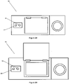
- the dosing device can be optically hidden between other items to be washed in the position of use in the plate holder of a dish drawer in a dishwasher.
- the corresponding light signals can also be guided into the head area of the cartridge, for example, so that the light signals can be seen by the user even if the dosing device is positioned in the plate holder between other items to be washed, since when the dish drawer is properly loaded, the area at the top of the items to be washed and the cartridge usually remains uncovered.
- the light signal coupled into the light guide of the cartridge and passing through the light guide is also possible for the light signal coupled into the light guide of the cartridge and passing through the light guide to be detectable by a sensor located on the dosing device. This is explained in more detail in a subsequent section.
- the dosing device for dispensing at least one detergent and/or cleaning agent preparation into the interior of a household appliance comprises at least one optical transmitter unit, the optical transmitter unit being configured in such a way that signals from the transmitter unit are converted into a system that can be coupled to the dosing device Cartridge can be coupled and signals from the transmitter unit can be radiated into the environment of the dosing device.
- both a signal transmission between the dosing device and, for example, a household appliance such as a dishwasher and the signal entry into a cartridge can be realized by means of an optical transmission unit.
- the optical transmission unit can be an LED, which preferably emits light in the visible and/or IR range. It is also conceivable to use another suitable optical transmission unit, such as a laser diode. An optical transmission unit is to be used that emits light in the wavelength range between 600-800nm.
- the dosing device can include at least one optical receiving unit.
- This makes it possible, for example, for the dosing device to be able to receive signals from an optical transmission unit arranged in the household appliance.
- This can be implemented by any suitable optical receiving unit, such as photocells, photomultipliers, semiconductor detectors, photodiodes, photoresistors, solar cells, phototransistors, CCD and/or CMOS image sensors.
- the optical receiving unit is suitable for receiving light in the wavelength range of 600-800nm.
- the optical receiving unit on the dosing device can also be designed such that the signals that can be coupled from the transmitting unit into a cartridge coupled to the dosing device can be decoupled from the cartridge and can be detected by the optical receiving unit of the dosing device.
- the signals transmitted by the transmitter unit into the surroundings of the dosing device can preferably represent information regarding operating states or control commands.
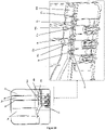
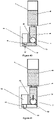
- the dosing device for dispensing at least one free-flowing detergent and/or cleaning agent preparation into the interior of a household appliance can, in particular, have a dosing chamber, the cartridge that can be coupled to the dosing device is connected in a communicating manner to a dosing chamber inlet located in the dosing device, so that when the dosing device is in the position of use, the preparation is released by the force of gravity of the cartridge flows into the dosing chamber, with a dosing chamber outlet following the dosing chamber inlet in the direction of gravity being arranged, which can be closed by a valve, with a floating body being arranged in the dosing chamber, the density of which is lower than the density of the preparation, the floating body being designed in this way that preparation can flow around and/or through the floating body and the floating body and the metering chamber inlet are configured in such a way that the metering chamber inlet can be closed by the floating body.
- the floating body can close the dosing chamber inlet in a sealing or non-sealing manner.
- the floating body rests against the dosing chamber inlet, but does not seal it against the inflow of preparation from the cartridge, so that an exchange of preparation between the cartridge and the dosing chamber is possible.
- the float body acts as a targeted throttle, which minimizes the slippage between the dosing chamber inlet and dosing chamber outlet when the valve opens and thus also determines the dosing accuracy.
- the floating body and the dosing chamber can be designed as a self-closing valve, on the one hand in order to achieve the lowest possible energy consumption in an energy self-sufficient dosing device; on the other hand, a defined amount of preparation, which roughly corresponds to the filling volume of the dosing chamber, is released.
- the floating body has a rate of rise of 1.5 mm/sec to 25 mm/sec, preferably 2 mm/sec to 20 mm/sec. sec, particularly preferably 2.5 mm/sec to 17.5 mm/sec in the detergent and/or cleaning agent preparation. This ensures that the dosing chamber inlet is closed sufficiently quickly by the rising floating body and thus that the interval between two doses of preparation is sufficiently short.
- the rising speed of the floating body can advantageously also be stored in the control unit of the dosing device that actuates the valve. This makes it possible to also switch the valve in such a way that a delivery of preparation greater than the volume of the dosing chamber is realized.
- the valve is then opened again before the float reaches its upper closed position at the metering chamber inlet and closes the metering chamber inlet.
- the float and the dosing chamber are configured in such a way that, in the delivery position of the valve assigned to the dosing chamber outlet, the rising speed of the float in the washing and/or cleaning agent preparation is smaller than the flow rate of the preparation surrounding the floating body from the dosing chamber.
- the floating body prefferably be essentially spherical.
- the floating body can also be essentially cylindrical.
- the metering chamber is substantially cylindrical. Furthermore, it is advantageous that the diameter of the dosing chamber is slightly larger than the diameter of the cylindrical or spherical floating body, so that there is a slippage between the dosing chamber and the floating body with regard to the preparation.
- the floating body is made of a foamed, polymeric material, in particular foamed PP.
- the dosing chamber is L-shaped.
- an orifice can be arranged in the dosing chamber between the dosing chamber inlet and dosing chamber outlet, with the orifice opening being designed in such a way that it can be closed by the floating body in a sealing or non-sealing manner, with the floating body preferably being arranged between the orifice and the dosing chamber inlet.
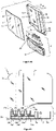
- the dosing device comprises a component carrier on which at least the actuator and the closure element as well as the energy source and/or the control unit and/or the sensor unit and/or the dosing chamber are arranged.
- the component carrier has receptacles for the components mentioned and/or the components are formed in one piece with the component carrier.
- the receptacles for the components in the component carrier can be provided for a non-positive, positive and/or material connection between a corresponding component and the corresponding receptacle.
- the dosing chamber, the actuator, the closure element, the energy source, the control unit and/or the sensor unit are each detachably arranged on the component carrier.
- the energy source, the control unit and the sensor unit are combined in one assembly and arranged on or in the component carrier.
- the energy source, the control unit and the sensor unit are combined in one assembly. This can be implemented, for example, by arranging the energy source, the control unit and the sensor unit on a common electrical printed circuit board.
- the component carrier is designed like a trough and is manufactured as an injection molded part. It is particularly preferred that the dosing chamber is formed in one piece with the component carrier.
- the component carrier Due to the component carrier, a largely simple automatic assembly with the necessary components of the dosing device is possible.
- the component carrier can thus preferably be automatically prefabricated as a whole and assembled to form a dosing device.
- the trough-like component carrier can be sealed in a liquid-tight manner by a cover-like closure element, for example, after assembly.
- the closure element can be designed, for example, as a film that is connected to the component carrier in a liquid-tight, materially bonded manner and forms one or more liquid-tight chambers with the trough-like component carrier.
- the closure element can also be a console into which the component carrier can be inserted, the console and the component carrier forming the dosing device when assembled.
- the component carrier and the console work together in such a way that a liquid-tight connection is formed between the component carrier and the console, so that no flushing water can get into the interior of the dispensing device or the component carrier.
- the receptacle for the actuator on the component carrier is arranged above the dispensing chamber in the direction of gravity, as a result of which a compact design of the dispensing device can be implemented.
- the compact design can be further optimized by arranging the dosing chamber inlet on the component carrier above the receptacle of the actuator when the dosing device is in the position of use is. It is also preferable for the components to be arranged on the component carrier essentially in a row with one another, in particular along the longitudinal axis of the component carrier.
- the receptacle for the actuator has an opening which is in line with the dosing chamber outlet, so that a closure element can be moved back and forth by the actuator through the opening and the dosing chamber outlet.
- the component carrier is formed from a transparent material.
- the component carrier comprises at least one optical fiber, via which light from the vicinity of the dispensing device can be guided to an optical transmitter and/or receiver unit into and/or out of the interior(s) of the dispensing device or the component carrier, with the optical fiber in particular is formed in one piece with the transparent component carrier.
- At least one opening is provided in the dosing device, through which light from the surroundings of the dosing device can be coupled into and/or out of the light guide.
- an actuator is a device that converts an input variable into a different type of output variable and with which an object is moved or its movement is generated, the actuator being coupled to at least one closure element in such a way that the preparation is released directly or indirectly at least one cartridge chamber can be effected.
- the actuator can be driven by means of drives selected from the group of gravity drives, ion drives, electric drives, motor drives, hydraulic drives, pneumatic drives, gear drives, threaded spindle drives, ball screws, linear drives, roller screws, toothed worm drives, piezoelectric drives, chain drives, and/or recoil drives.
- drives selected from the group of gravity drives, ion drives, electric drives, motor drives, hydraulic drives, pneumatic drives, gear drives, threaded spindle drives, ball screws, linear drives, roller screws, toothed worm drives, piezoelectric drives, chain drives, and/or recoil drives.
- the actuator can be formed from an electric motor that is coupled to a gear that converts the rotary movement of the motor into a linear movement of a carriage that is coupled to the gear. This is particularly advantageous in the case of a slim, plate-shaped design of the dosing unit.
- At least one magnetic element can be arranged on the actuator, which causes product to be dispensed from the container with a magnetic element of the same polarity on a dispenser as soon as the two magnetic elements are positioned against one another in such a way that magnetic repulsion of the magnetic elements of the same polarity is achieved and a non-contact release mechanism is implemented.
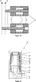
- the actuator is a bistable solenoid which, together with a closure element which engages in the bistable solenoid and is designed as a plunger, forms a pulse-controlled, bistable valve.
- Bistable lifting magnets are electromechanical magnets with a linear direction of movement, whereby the plunger locks in any end position without current.
- Bistable solenoids or valves are known in the prior art.
- a bistable valve requires an impulse to change the valve position (open/closed) and then remains in this position until a counter impulse is sent to the valve. Therefore one also speaks of a pulse-controlled valve.
- a major advantage of such impulse-controlled valves is that they do not consume any energy to remain in the valve end positions, the closed position and release position, but only require an energy impulse to change the valve positions, so the valve end positions can be considered stable.
- a bistable valve remains in the switching position which last received a control signal.
- the closure element (plunger core) is moved to an end position by a current pulse.
- the current is switched off, the locking element holds the position.
- the locking element is moved to the other end position by a current pulse.
- the current is switched off, the locking element holds the position.
- a bistable property of lifting magnets can be realized in different ways.
- a division of the coil is known. The coil is divided more or less in the middle so that a gap is created. A permanent magnet is inserted into this gap. The plunger itself is turned both at the front and at the back so that in the respective end position it has a flat surface to the frame of the magnet. The magnetic field of the permanent magnet flows over this surface. The diving core sticks here.
- the use of two separate coils is also possible.
- the principle is similar to that of the split-coil bistable solenoid. The difference is that they are actually electrically two different coils. These are controlled separately, depending on the direction in which the plunger is to be moved.
- the closure element is coupled to the actuator in such a way that the closure element can be moved by the actuator into a closed position and into an open position (dispensing position), the closure element being designed as an open/close valve element, that the actuator is designed in such a way that it assumes one of two end positions, controlled by a suitable pulse, and stably maintains the end position reached without control, and that the combination thus forms a pulse-controlled, bistable open/close valve.
- the actuator can be designed for this purpose as a bistable solenoid with a space accommodating an armature and an outer receiving space surrounding it.
- the armature of the bistable solenoid may be configured to form or be coupled to the closure member.
- the space of the actuator accommodating the armature can be separated in a liquid-tight and preferably also gas-tight manner from the outer receiving space of the actuator.
- At least the outer surface of the anchor from a material that cannot be attacked by the washing or cleaning agent to be dosed, in particular from a plastic material.
- the armature preferably comprises a core made of a magnetizable, in particular a ferromagnetic material and a permanent magnet positioned in the outer receiving space, with a coil being arranged at each of its two axial ends.
- permanent magnets are arranged axially antipole in the armature at its axial ends and that yoke rings made of a ferromagnetic material, in particular iron, and between these a coil winding are arranged in the outer receiving space at both axial ends.
- the axial spacing of the yoke rings is greater than the axial spacing of the permanent magnets.
- yoke rings can be arranged in the armature at its axial ends, with permanent magnets being arranged axially anti-pole in the outer receiving space at both axial ends and a coil winding being arranged between them.
- the axial spacing of the permanent magnets is preferably greater than the axial spacing of the yoke rings.
- the one actuator/closure element combination is provided in a dosing device of a dosing system with a cartridge for free-flowing detergents or cleaning agents with a plurality of chambers for spatially separated accommodation of different preparations of a detergent or cleaning agent and with a cartridge that can be coupled
- the dosing device has: an energy source, a control unit, a sensor unit, an actuator which is connected to the energy source and the control unit in such a way that a control signal from the control unit causes the actuator to be actuated, a closure element which is connected to the actuator in the Art is coupled in that it can be moved by the actuator into a closed position and into an open position (dispensing position), at least one dosing chamber which is connected in a communicating manner to at least one of the cartridge chambers of the cartridge when the dosing device is assembled with a cartridge, wherein the dosing chamber has an inlet for washing or cleaning agent to flow in from a cartridge chamber and an outlet for washing or cleaning agent to flow out of
- the actuator is arranged in a component carrier in such a way that, when the dispensing device is in the operating position, a receptacle for the actuator is arranged on the component carrier in the direction of gravity above the dispensing chamber. It is particularly advantageous here that, when the dosing device is in the position of use, the inlet of the dosing chamber is arranged on the component carrier above the receptacle of the actuator.
- the dosing device has a component carrier in which, in the operating position of the dosing device, a receptacle for the actuator is arranged on the component carrier laterally next to the dosing chamber.
- the receptacle for the actuator preferably has an opening which is in line with the outlet of the metering chamber, the closure element being movable back and forth by the actuator through the opening to the outlet.
- a closure element within the meaning of this application is a component on which the actuator acts and which, as a result of this action, causes the opening or closing of an outlet opening.
- the closure element can be, for example, valves that can be brought into a product delivery position or closed position by the actuator.
- the embodiment of the closure element and the actuator in the form of a magnetic valve is particularly preferred, in which the dispenser is configured by the valve and the actuator by the electromagnetic or piezoelectric drive of the magnetic valve.
- the use of solenoid valves allows the quantity and timing of the dosing to be regulated very precisely.
- a sensor within the meaning of this application is a measured variable recorder or sensor that can qualitatively or quantitatively record specific physical or chemical properties and/or the material composition of its environment as a measured variable.
- the dosing unit preferably has at least one sensor that is suitable for detecting a temperature.
- the temperature sensor is designed in particular to detect a water temperature.
- the dosing unit includes a sensor for detecting the conductivity, whereby in particular the presence of water or the spraying of water, in particular in a dishwasher, is detected.
- the dosing unit has a sensor which can determine physical, chemical and/or mechanical parameters from the surroundings of the dosing unit.
- the sensor unit can include one or more active and/or passive sensors for the qualitative and/or quantitative detection of mechanical, electrical, physical and/or chemical variables, which are sent to the control unit as control signals.
- the sensors of the sensor unit from the group of timers, temperature sensors, infrared sensors, brightness sensors, temperature sensors, movement sensors, strain sensors, speed sensors, proximity sensors, flow sensors, color sensors, gas sensors, vibration sensors, pressure sensors, conductivity sensors, turbidity sensors, sound pressure sensors, "Lab-on-a -Chip” sensors, force sensors, acceleration sensors, inclination sensors, pH sensors, humidity sensors, magnetic field sensors, RFID sensors, magnetic field sensors, Hall sensors, biochips, odor sensors, hydrogen sulfide sensors and/or MEMS sensors.
- Suitable flow sensors can be selected from the group of orifice flow sensors, magnetic-inductive flow meters, mass flow measurement using the Coriolis method, vortex meter flow measurement methods, ultrasonic flow measurement methods, variable area flow measurement, annular piston flow measurement, thermal mass flow measurement or differential pressure flow measurement.
- At least two sensor units are provided for measuring mutually different parameters, one sensor unit being a conductivity sensor and another sensor unit being a temperature sensor. Furthermore, it is preferred that at least one sensor unit is a brightness sensor.
- the sensors are designed to detect the start, course and end of a washing program.
- the sensor combinations listed in the following table can be used - by way of example and not exhaustively sensor 1 sensor 2 sensor 3 sensor 4 conductivity sensor temperature sensor conductivity sensor temperature sensor brightness sensor conductivity sensor temperature sensor brightness sensor turbidity sensor sound sensor temperature sensor
- the conductivity sensor can be used, for example, to detect whether the conductivity sensor is wet with water, so that it can be used to determine, for example, whether there is water in the dishwasher.
- Washing programs usually have a characteristic temperature curve, which is determined, among other things, by the heating of the washing water and the drying of the washware, which can be detected by a temperature sensor.
- a brightness sensor can be used, for example, to detect the incidence of light inside a dishwasher when the dishwasher door is opened, which can be used to indicate the end of the washing program, for example.
- a turbidity sensor can also be provided. From this, for example, a dosing program in the dosing device that applies to the determined contamination situation can also be selected.
- a temperature-dependent viscosity curve of at least one preparation is stored in the control unit, with the dosage being adjusted by the control unit according to the temperature and thus the viscosity of the preparation.
- a device for directly determining the viscosity of the preparation is provided.
- the data line between the sensor and the control unit can be realized via an electrically conductive cable or wirelessly.
- at least one sensor is or can be positioned outside of the dosing device inside a dishwasher and a data line—in particular wirelessly—is designed to transmit the measurement data from the sensor to the dosing device.
- a wireless data line is formed in particular by the transmission of electromagnetic waves or light. It is preferred to design a wireless data line according to standardized standards such as Bluetooth, IrDA, IEEE 802, GSM, UMTS, etc.
- At least one sensor unit is arranged on or in the control unit.
- the sensor unit is arranged on the bottom of the dosing device, with the bottom of the dosing device being directed downwards in the direction of gravity in the position of use. It is particularly preferred that the sensor unit includes a temperature and/or a conductivity sensor. Such a configuration ensures that the dishwasher's spray arms will bring water onto the underside of the dispenser and thus into contact with the sensor. Due to the fact that the distance between the spray arms and the sensor is as small as possible due to the bottom arrangement of the sensor, the water experiences only a slight cooling between the outlet at the spray arms and the contact with the sensor, so that the most accurate possible temperature measurement can be carried out .
- the energy consumers of the dosing device in particular the control unit, can be connected to the energy source, including an on/off switch, and the energy source can only be switched on after the The on-state of the on/off switch is charged, with a sensor unit forming the on/off switch or being connected to it and switching it on.
- the sensor unit has two contacts in contact with the environment at the bottom on the bottom of the dosing device, in particular designed as contact pins protruding downwards from the bottom, that one contact as an anode contact and the other contact as a cathode contact the energy source is switched on and that without an electrically conductive connection between the contacts, the on/off switch in the off state remains in the off state and when an electrically conductive connection is created between the contacts, the on/off switch in the off state remains switch turns to the on state.
- the on/off switch is provided or combined with a self-locking circuit which ensures or ensures that the power supply to the energy consumers is self-retaining after the on/off switch has reached the on state until a switch-off signal from the control unit is received .
- the on/off switch can be designed in particular as a transistor circuit. It is preferable for the transistor of the on/off switch to be designed as a pnp transistor and to be connected to the supply voltage with the emitter, if necessary via a control circuit, to the supply voltage with the collector, if necessary via a control circuit, to ground and to the cathode contact and is connected to the base on the one hand, possibly via a control circuit, to the supply voltage, on the other hand, possibly via a control circuit, to the anode contact.
- the control circuit preferably has at least one control resistor, which is designed in particular as a resistance-voltage divider.
- a sensor unit designed as a conductivity sensor which has two contacts in contact with the environment at the bottom of the dosing device and that the anode contact of the on/off -Sensor unit is also the anode contact of the sensor unit forming the conductivity sensor.
- the sensor unit forming the temperature sensor can be integrated into a contact, in particular the cathode contact, of the sensor unit forming the conductivity sensor.
- the contact receiving the temperature sensor of the sensor unit forming the conductivity sensor preferably be designed as a hollow contact pin, in which the temperature sensor of the sensor unit forming the temperature sensor is arranged.
- the energy source, the control unit and the sensor unit are combined in one assembly and arranged on or in the component carrier.
- the contacts of a conductivity sensor arranged on the bottom are surrounded by an electrically conductive silicone.
- the conductivity sensor can be designed in particular in the form of a resistance measurement between two spaced-apart contacts which are in contact with the surroundings of the dosing device.
- the silicone is embedded flush in the bottom of the dosing device.
- the silicone has an approximately circular base. The silicone shows good wettability with water and thus delivers good measurement results with regard to the detection of water in the dishwasher.
- a control unit within the meaning of this application is a device that is suitable for influencing the transport of material, energy and/or information. To this end, the control unit influences actuators with the aid of information, in particular measurement signals from the sensor unit, which it processes in accordance with the control objective.
- control unit can be a programmable microprocessor.
- a plurality of dosing programs are stored on the microprocessor, which in a particularly preferred embodiment can be selected and executed according to the container coupled to the dosing device.
- control unit has no connection to the possibly existing control of the household appliance. Accordingly, no information, in particular electrical, optical or electromagnetic signals, is exchanged directly between the control unit and the control of the household appliance.
- control unit is coupled to the existing control of the household appliance.
- This coupling is preferably implemented wirelessly.
- a transmitter on or in a dishwasher preferably on or in the dosing chamber let into the door of the dishwasher, which wirelessly transmits a signal to the dosing unit when the control of the household appliance removes the dosing, for example of a cleaning agent from the Dosing chamber or caused by rinse aid.
- control unit Several programs for releasing different preparations or for releasing products in different applications can be stored in the control unit.
- the corresponding program can be called up by corresponding RFID labels or geometric information carriers formed on the container.
- the same control unit for a number of applications, for example for dosing detergents in dishwashers, for dispensing perfumes in room scenting, for applying cleaning substances to a toilet bowl, etc.
- control unit can be configured in such a way that on the one hand the dosing takes place in a sufficiently short time to ensure a good cleaning result and on the other hand the preparation is not dosed so quickly that gelling of the preparation surge occurs.
- This can be realized, for example, by an interval-like release, with the individual dosing intervals being set in such a way that the correspondingly dosed amount dissolves completely during a cleaning cycle.
- the dosing intervals for dispensing a preparation are between 30-90 seconds, particularly preferably 45-75 seconds.
- Preparations can be dispensed from the dosing device sequentially or simultaneously.
- the dishwasher and the dosing device work together in such a way that 1 mg to 1 g of surfactant are released in the final rinse program of the dishwasher per m 2 of washing compartment wall surface. This ensures that the walls of the wash chamber retain their gloss level even after a large number of wash cycles and that the dosing system retains its optical transmission capability.
- the dishwasher and the dosing device interact in such a way that at least one enzyme-containing preparation and/or alkaline preparation is released in the prewash and/or main wash program of the dishwasher, with the release of the enzyme-containing preparation preferably occurring before the release the alkaline preparation takes place.
- the dishwasher and the dosing device work together in such a way that 0.1 mg - 250 mg of enzyme protein are released in the pre-wash and/or main wash program of the dishwasher per m 2 of the wall surface of the wash compartment, which further improves or reduces the gloss level of the wash compartment walls .is retained even after a large number of rinsing cycles.
- data such as control and/or dosing programs of the control unit or operating parameters or protocols stored by the control unit can be read from the control unit or loaded into the control unit.
- This can be implemented, for example, by means of the optical interface, with the optical interface being correspondingly connected to the control unit.
- the data to be transmitted is then encoded and sent or received as light signals in the wavelength range between 600-800 nm.
- a sensor present in the dosing device to transmit data from and/or to the control unit.
- the contacts of a conductivity sensor which are connected to the control unit and which provides a conductivity determination by means of a resistance measurement at the contacts of the conductivity sensor, can be used for data transmission.
- control unit can be used to implement a method for operating a dosing device that is not permanently connected to a household appliance for dispensing at least one detergent and/or cleaning agent preparation into the interior of the household appliance, with at least one dosing program being stored in the control unit, and the control unit having at least an actuator located in the dosing device interacts in such a way that washing and/or cleaning agent preparation can be released from the dosing device into the interior of the household appliance
- the dosing device comprises at least one receiving unit for signals which are transmitted by at least one transmitting unit arranged in the household appliance and at least one part the signals in the dosing device-side control unit are converted into control commands for the actuators of the dosing device, with the receipt of the signals being monitored by the dosing device side by means of the control unit and when the signals are not received at the dosing device t a dosing program from the control unit of the dosing device is activated.
- the signal on the household appliance side is transmitted into the interior of the household appliance at predefined, periodic time intervals by the transmitter unit on the household appliance side.
- the transmitter unit is deposited in the control unit of the dosing device and in the household appliance. If the contact between the transmitter unit of the household appliance breaks after a signal has been received at the dosing device, this break can be detected by comparing the time that has elapsed since the last signal received and the time in which the receipt of a subsequent signal is expected after the defined, periodic time interval , can be determined on the dosing device side.
- the periodic signal intervals are selected to be between 1 second and 10 minutes, preferably between 5 seconds and 7 minutes, particularly preferably between 10 seconds and 5 minutes. It is particularly preferred that the periodic signal intervals are chosen to be between 3 minutes and 5 minutes.
- control unit of the dosing device activates a dosing program from the control unit of the dosing device after a predefined time interval t 1-2 beginning with t 1 in which no further domestic appliance-side signal has been received from the dosing device.
- the control unit evaluates the number and/or time sequence of the signals received from the dosing device in such a way that a dosing program is activated in the control unit in accordance with the result of the evaluation.
- This makes it possible, for example, to determine the duration of a washing program in a dishwasher from its start by comparing the point in time when the first signal was received to the point in time when the signal was lost, so that a suitable dosing program corresponding to the progress of the washing program can be selected in accordance with the progress of the washing program the control unit of the dosing device is activated.
- a dosing program stored in the control unit of the dosing device is activated in the control unit, starting from a defined program step corresponding to the progress of the washing program. It is thus possible, for example, in the event of a signal interruption in the main wash cycle of a wash program, to activate a dosing program in the dosing device that is provided for a main wash cycle and subsequent wash program sections.
- the signals transmitted by the transmitter unit on the household appliance side include at least one control signal.
- the signals transmitted by the household appliance transmission unit include at least one monitoring signal.
- At least one dosing program stored in the control unit includes a dosing program of the household appliance. This makes it possible for the dosing device to continue a dosing program started by the household appliance if the signal between the household appliance and the dosing device breaks.
- the dosing programs stored in the control unit of the dosing device include the dosing programs of the household appliance.
- an acoustic and/or visual signal that can be perceived by a user can advantageously be generated that indicates the loss of the signal.
- a monitoring signal and/or control signal to the household appliance can be effected manually by a user.
- This allows a user to check, for example, whether there is signal reception between the transmitter unit of the household appliance and the dispenser in a position of the dispenser within the household appliance that he has selected.
- This can be implemented, for example, by an operating element configured on the household appliance, such as a button or switch, which emits a monitoring and/or control signal when actuated.
- an energy source is understood to mean a component of the dosing system which is expedient to provide energy suitable for operating the dosing system or the dosing device.
- the energy source is preferably designed in such a way that the dosing system is self-sufficient.
- the energy source preferably provides electrical energy.
- the energy source can be, for example, a battery, an accumulator, a power supply unit, solar cells or the like.
- the energy source prefferably be exchangeable, for example in the form of an exchangeable battery.
- a battery can be selected, for example, from the group of alkaline-manganese batteries, zinc-carbon batteries, nickel-oxyhydroxide batteries, lithium batteries, lithium-iron sulfide batteries, zinc-air batteries, zinc-chloride batteries, mercuric oxide-zinc batteries and/or silver oxide-zinc batteries.
- Suitable accumulators are lead accumulators (lead dioxide/lead), nickel-cadmium accumulators, nickel-metal hydride accumulators, Lithium-ion batteries, lithium-polymer batteries, alkaline-manganese batteries, silver-zinc batteries, nickel-hydrogen batteries, zinc-bromine batteries, sodium-nickel chloride batteries and/or nickel-iron batteries.
- the accumulator can in particular be designed in such a way that it can be recharged by induction.
- mechanical energy sources consisting of one or more helical springs, torsion springs or torsion bar springs, spiral springs, air springs/gas pressure springs and/or elastomer springs.
- the energy source is dimensioned in such a way that the dosing device can run through about 300 dosing cycles before the energy source is exhausted. It is particularly preferred that the energy source can go through between 1 and 300 dosing cycles, most preferably between 10 and 300, further preferably between 100 and 300, before the energy source is exhausted.
- means for energy conversion can be provided in or on the dosing unit, which generate a voltage by means of which the accumulator is charged.
- these means can be designed as a dynamo, which is driven by the water currents during a wash cycle in a dishwasher and delivers the voltage generated in this way to the accumulator.
- An optical transmitter and/or receiver unit is preferably arranged within the dosing device, in particular in or on the component carrier, in order to protect the electrical and/or optical components of the transmitter and/or receiver unit from the effects of splashing and rinsing water.
- an optical fiber is arranged between the optical transmitter and/or receiver unit and the surroundings of the dosing device, which has at least a light transmittance of 75%.
- the light guide is preferably made of a transparent plastic with a light transmittance of at least 75%.
- the transmittance of the light guide is defined as the transmittance between the surface of the light guide on which the light from the area around the dosing device is coupled into the light guide and the surface on which the light is coupled out of the light guide to the optical transmitter and/or receiver unit.
- the transmittance can be determined according to DIN5036.
- the light guide comprises at least one in-coupling and/or out-coupling point at which light is coupled in and out from an optical transmitting and/or receiving unit and/or from the surroundings of the dosing device.
- the light guide is formed in one piece with the component carrier.
- the component carrier is therefore advantageously formed from a transparent material.
- An opening is provided in the dosing device to accommodate the coupling-in and/or coupling-out point of the light guide and to establish an optical connection between the light guide and the environment.
- the coupling-in and/or coupling-out point can be arranged in the lateral surface in the bottom or top of the dosing device.
- the light guide can also be constructed in multiple layers and/or in multiple pieces from the same or different materials. It is also possible to provide an air gap between a light guide formed in multiple layers and/or in multiple pieces.
- the transmittance of the light guide is understood to be between the surface of the light guide on which the light from the area around the dosing device is coupled into the light guide and the surface on which the light from the light guide is transmitted to the optical transmission and/or or receiving unit is decoupled.
- At least two coupling and decoupling points of the light guide with the environment are provided. It is particularly advantageous that the coupling and decoupling points on the dosing device are essentially opposite one another.
- the dosing system has at least one oscillating atomizer, via which it is possible to convert a preparation into the gas phase or to keep it in the gas phase.
- the oscillating atomizer via which it is possible to convert a preparation into the gas phase or to keep it in the gas phase.
- This embodiment is particularly advantageous when used in a dishwasher, where a corresponding release of preparation into the gas phase takes place in a closable washing compartment.
- the preparation introduced into the gas phase can be distributed evenly in the washing compartment and condense on the items to be washed in the dishwasher.
- the preparation released by the oscillating atomizer can be selected from the group of preparations containing surfactants, preparations containing enzymes, odor-neutralizing preparations, biocidal preparations, antibacterial preparations.
- a uniform layer of the corresponding cleaning preparation is applied to the surface of the items to be washed. It is particularly preferred that the entire surface of the items to be washed is wetted by the cleaning preparation.
- a suitable cleaning preparation can suppress bad odors caused by biological decomposition processes of food residues adhering to the items to be washed.
- a corresponding cleaning preparation can cause the food residues possibly adhering to the items to be washed to "soak" so that they can be easily and completely removed in the dishwasher's cleaning program, particularly in the case of low-temperature programs.
- a preparation to the items to be washed by means of the oscillating atomizer after the end of a cleaning program of a dishwasher.
- This can be, for example, an antibacterial preparation or a preparation for modifying surfaces.
- the dosing system according to the invention comprises at least one first aqueous preparation containing surfactants, which in particular has a pH of less than 5.5, preferably less than 4, particularly preferably less than 3.5 (10% solution, 20° C.).
- the acidic setting of the surfactant phase makes it possible in particular to prevent limescale deposits on the walls of the washing compartment, which can reduce the degree of gloss and the reflectivity of the walls.
- such a surfactant preparation can be used to keep the degree of transmission of the light guide between the optical transmitter and/or receiver unit of the dosing device and the surroundings of the dosing device constant, even over a large number of rinsing cycles.
- wireless signal transmission for controlling the dosing systems positioned in the washing compartment is guaranteed and improved according to the invention by means of a specific surfactant-containing preparation to be released in the rinse cycle.
- this preparation is also characterized in particular by its pH below 5.5 (10% solution, 20° C.).
- the preparations according to the invention contain acidifying agents to adjust the pH.
- the proportion by weight of the acid(s) in the total weight of the preparation according to the invention, based on the total weight of the preparation, is preferably between 0.05 and 10% by weight, preferably between 0.1 and 8% by weight and in particular between 0.2 and 5% by weight.
- organic acids are suitable as acidifying agents, organic acids being particularly preferred in the context of the present application for reasons of consumer protection and handling safety.
- Particularly preferred organic acids are the mono-, oligo- and polycarboxylic acids, in particular citric acid, acetic acid, tartaric acid, succinic acid, glutaric acid, malonic acid, adipic acid, maleic acid, fumaric acid, oxalic acid and the homo- or copolymeric polycarboxylic acids.
- Organic sulfonic acids such as amidosulfonic acids can also be used.
- Particularly preferred preparations according to the invention contain, based on their total weight, between 0.05 and 10% by weight, preferably between 0.1 and 8% by weight and in particular between 0.2 and 5% by weight, of acetic acid and/or citric acid.
- preparations according to the invention can also contain salts of the abovementioned acids as buffer substances.
- the alkali metal salts are preferred here, and among these in turn the sodium or potassium salts.
- the surfactants form a second essential component of preparations according to the invention.
- the group of surfactants also includes, in particular, the nonionic surfactants used with particular preference.
- nonionic surfactants known to those skilled in the art can be used as nonionic surfactants.
- suitable nonionic surfactants are alkyl glycosides of the general formula RO(G) x , where R is a primary straight-chain or methyl-branched aliphatic radical, especially methyl-branched in the 2-position, having 8 to 22, preferably 12 to 18, carbon atoms and G is the symbol is, which is a glucose unit with 5 or 6 carbon atoms, preferably glucose.
- the degree of oligomerization x which indicates the distribution of monoglycosides and oligoglycosides, is any number between 1 and 10; preferably x is from 1.2 to 1.4.
- Nonionic surfactants of the amine oxide type for example N-cocoalkyl-N,N-dimethylamine oxide and N-tallowalkyl-N,N-dihydroxyethylamine oxide, and the fatty acid alkanolamide type can also be suitable.
- the amount of these nonionic surfactants is preferably not more than that of the ethoxylated fatty alcohols, in particular not more than half of it.
- nonionic surfactants which are used either as the sole nonionic surfactant or in combination with other nonionic surfactants, are alkoxylated, preferably ethoxylated or ethoxylated and propoxylated fatty acid alkyl esters, preferably having 1 to 4 carbon atoms in the alkyl chain.
- Low-foaming nonionic surfactants are used as preferred surfactants.
- Detergents or cleaning agents, in particular cleaning agents for machine dishwashing particularly preferably contain nonionic surfactants from the group of alkoxylated alcohols.
- the nonionic surfactants used are preferably alkoxylated, advantageously ethoxylated, in particular primary alcohols preferably having 8 to 18 carbon atoms and an average of 1 to 12 moles of ethylene oxide (EO) per mole of alcohol, in which the alcohol radical can be linear or preferably methyl-branched in the 2-position or may contain linear and methyl-branched radicals in the mixture, such as are usually present in oxo alcohol radicals.
- EO ethylene oxide
- alcohol ethoxylates with linear radicals from alcohols of natural origin with 12 to 18 carbon atoms for example from coconut, palm, tallow or oleyl alcohol, and an average of 2 to 8 moles of EO per mole of alcohol are preferred.
- Preferred ethoxylated alcohols include, for example, C 12-14 alcohols with 3 EO or 4 EO, C 9-11 alcohol with 7 EO, C 13-15 alcohols with 3 EO, 5 EO, 7 EO or 8 EO, C C 12-18 alcohols with 3 EO, 5 EO or 7 EO and mixtures of these, such as mixtures of C 12-14 alcohol with 3 EO and C 12-18 alcohol with 5 EO.
- the degrees of ethoxylation given represent statistical mean values which can correspond to a whole or a fractional number for a specific product.
- Preferred alcohol ethoxylates have a narrow homolog distribution (narrow range ethoxylates, NRE).
- fatty alcohols with more than 12 EO can also be used. Examples of this are tallow fatty alcohol with 14 EO, 25 EO, 30 EO or 40 EO.
- ethoxylated nonionic surfactants consisting of C6-20 monohydroxyalkanols or C6-20 alkylphenols or C16-20 fatty alcohols and more than 12 moles, preferably more than 15 moles and in particular more than 20 moles of ethylene oxide per mole Alcohol were obtained used.
- a particularly preferred nonionic surfactant is obtained from a straight-chain fatty alcohol having 16 to 20 carbon atoms (C 16-20 alcohol), preferably a C 18 alcohol and at least 12 moles, preferably at least 15 moles and in particular at least 20 moles of ethylene oxide.
- C 16-20 alcohol straight-chain fatty alcohol having 16 to 20 carbon atoms
- C 18 alcohol preferably a C 18 alcohol and at least 12 moles, preferably at least 15 moles and in particular at least 20 moles of ethylene oxide.
- the so-called “narrow range ethoxylates” are particularly preferred.
- Nonionic surfactants which have a melting point above room temperature are particularly preferred.
- Nonionic surfactants from the group of alkoxylated alcohols particularly preferably from the group of mixed alkoxylated alcohols and in particular from the group of EO-AO-EO nonionic surfactants, are also used with particular preference.
- the nonionic surfactant which is solid at room temperature preferably has propylene oxide units in the molecule.
- Such PO units preferably make up up to 25% by weight, particularly preferably up to 20% by weight and in particular up to 15% by weight, of the total molar mass of the nonionic surfactant.
- Particularly preferred nonionic surfactants are ethoxylated monohydroxy alkanols or alkyl phenols which additionally have polyoxyethylene-polyoxypropylene block copolymer units.
- the alcohol or alkylphenol content of such nonionic surfactant molecules makes up preferably more than 30% by weight, particularly preferably more than 50% by weight and in particular more than 70% by weight of the total molar mass of such nonionic surfactants.
- Preferred agents are characterized in that they contain ethoxylated and propoxylated nonionic surfactants in which the propylene oxide units in the molecule make up up to 25% by weight, preferably up to 20% by weight and in particular up to 15% by weight of the total molar mass of the nonionic identify surfactants.
- Surfactants to be used with preference come from the groups of alkoxylated nonionic surfactants, in particular ethoxylated primary alcohols and mixtures of these surfactants with structurally complex surfactants such as polyoxypropylene/polyoxyethylene/polyoxypropylene ((PO/EO/PO) surfactants).
- Such (PO/EO/PO) nonionic surfactants are also distinguished by good foam control.
- nonionic surfactants to be used with particular preference, having melting points above room temperature contain 40 to 70% of one Polyoxypropylene/polyoxyethylene/polyoxypropylene block polymer blend comprising 75% by weight of a reverse block copolymer of polyoxyethylene and polyoxypropylene with 17 moles of ethylene oxide and 44 moles of propylene oxide and 25% by weight of a block copolymer of polyoxyethylene and polyoxypropylene initiated with trimethylolpropane and containing 24 moles of ethylene oxide and 99 moles of propylene oxide per mole of trimethylolpropane.
- low-foaming nonionic surfactants which have alternating ethylene oxide and alkylene oxide units have proven to be particularly preferred nonionic surfactants.
- nonionic surfactants of the general formula preferably in which R 1 is a straight-chain or branched, saturated or mono- or polyunsaturated C 6-24 -alkyl or -alkenyl radical; each group R 2 or R 3 is independently selected from -CH 3 , -CH 2 CH 3 , -CH 2 CH 2 -CH 3 , CH(CH 3 ) 2 and the indices w, x, y, z are independent of one another are integers from 1 to 6.
- the preferred nonionic surfactants of the above formula can be prepared from the corresponding alcohols R 1 —OH and ethylene or alkylene oxide by known methods.
- the radical R 1 in the above formula can vary depending on the origin of the alcohol. If native sources are used, the radical R 1 has an even number of carbon atoms and is usually unbranched, the linear radicals from alcohols of natural origin having 12 to 18 carbon atoms, for example from coconut, palm, tallow or oleyl alcohol, are preferred.
- Alcohols which can be obtained from synthetic sources are, for example, the Guerbet alcohols or a mixture of methyl-branched or linear and methyl-branched radicals in the 2-position, such as are usually present in oxo alcohol radicals.
- nonionic surfactants are preferred in which R 1 in the above formula is an alkyl radical with 6 to 24, preferably 8 to 20, particularly preferably 9 to 15 and in particular 9 to 11 carbon atoms.
- a suitable alkylene oxide unit which is present in the preferred nonionic surfactants alternating with the ethylene oxide unit, is, in addition to propylene oxide, in particular butylene oxide.
- R 2 or R 3 are independently selected from --CH 2 CH 2 --CH 3 or --CH(CH 3 ) 2 are also suitable.
- nonionic surfactants having a C 9-15 alkyl radical containing 1 to 4 ethylene oxide units followed by 1 to 4 propylene oxide units followed by 1 to 4 ethylene oxide units followed by 1 to 4 propylene oxide units.
- these surfactants have the required low viscosity and can be used with particular preference in accordance with the invention.
- R 1 -CH(OH)CH 2 O-(AO) w -(A'O) x -(A"O) y -(A"'O) z -R 2 in which R 1 and R 2 is independently a straight-chain or branched, saturated or mono- or polyunsaturated C 2-40 alkyl or alkenyl radical;
- A, A', A" and A'" independently represent a radical from the group -CH 2 CH 2 , -CH 2 CH 2 -CH 2 , -CH 2 -CH(CH 3 ), -CH 2 -CH 2 -CH 2 -CH 2 , -CH 2 -CH(CH 3 )-CH 2 -, -CH 2 -CH(CH 2 -CH 3 ); and
- w, x, y and z stand for values between 0.5 and 90, where x, y and/or z can also be 0 are preferred according to the invention.
- end-capped poly(oxyalkylated) nonionic surfactants which, according to the formula R 1 O[CH 2 CH 2 O] x CH 2 CH(OH)R 2 , in addition to a radical R 1 which represents linear or branched, saturated or unsaturated, aliphatic or aromatic hydrocarbon radicals having 2 to 30 carbon atoms, preferably having 4 to 22 carbon atoms, furthermore have a linear or branched, saturated or unsaturated, aliphatic or aromatic hydrocarbon radical R 2 having 1 to 30 carbon atoms, where x is a value between 1 and 90, preferably values between 30 and 80 and in particular values between 30 and 60.
- R 1 O[CH 2 CH(CH 3 )O] x [CH 2 CH 2 O] y CH 2 CH(OH)R 2 , in which R 1 is a linear or branched aliphatic hydrocarbon radical having 4 to 18 carbon atoms or mixtures thereof stands, R 2 denotes a linear or branched hydrocarbon radical having 2 to 26 carbon atoms or mixtures thereof and x has values between 0.5 and 1.5 and y has a value of at least 15.
- nonionic surfactants with a free hydroxyl group on one of the two terminal alkyl radicals can significantly improve the formation of deposits in machine dishwashing compared to conventional polyalkoxylated fatty alcohols without a free hydroxyl group.
- nonionic surfactants are the end-capped poly(oxyalkylated) nonionic surfactants of the formula R 1 O[CH 2 CH(R 3 )O] x [CH 2 ] k CH(OH)[CH 2 ] j OR 2 in which R 1 and R 2 represents linear or branched, saturated or unsaturated, aliphatic or aromatic hydrocarbon radicals having 1 to 30 carbon atoms, R 3 represents H or a methyl, ethyl, n-propyl, isopropyl, n-butyl, 2- butyl or 2-methyl-2-butyl radical, x for values between 1 and 30, k and j are between 1 and 12, preferably between 1 and 5.
- each R 3 in the above formula R 1 O[CH 2 CH(R 3 )O] x [CH 2 ] k CH(OH)[CH 2 ] j OR 2 can be different.
- R 1 and R 2 are preferably linear or branched, saturated or unsaturated, aliphatic or aromatic hydrocarbon radicals having 6 to 22 carbon atoms, radicals having 8 to 18 carbon atoms being particularly preferred.
- H, -CH 3 or -CH 2 CH 3 are particularly preferred for the radical R 3 .
- Particularly preferred values for x are in the range from 1 to 20, in particular from 6 to 15.
- each R 3 in the above formula may be different.
- the value 3 for x was selected here as an example and can certainly be larger, with the range of variation increasing with increasing x values and including, for example, a large number of (EO) groups combined with a small number of (PO) groups, or vice versa .
- R 1 , R 2 and R 3 are as defined above and x is a number from 1 to 30, preferably from 1 to 20 and in particular from 6 to 18.
- the specified carbon chain lengths and degrees of ethoxylation or alkoxylation of the aforementioned nonionic surfactants represent statistical averages, which can be a whole or a fractional number for a specific product. Due to the manufacturing process, commercial products of the formulas mentioned usually do not consist of an individual representative, but of mixtures, which means that average values and fractional numbers can result both for the C chain lengths and for the degrees of ethoxylation or degrees of alkoxylation.
- nonionic surfactants can be used not only as individual substances but also as surfactant mixtures of two, three, four or more surfactants.
- Surfactant mixtures are not mixtures of nonionic surfactants that fall under one of the above general formulas, but rather those mixtures that contain two, three, four or more nonionic surfactants that can be described by different of the aforementioned general formulas .
- the proportion by weight of the nonionic surfactants in the total weight of the preparation according to the invention is between 1.0 and 25% by weight, preferably between 2.0 and 20% by weight, preferably between 3.0 and 17% by weight in particular between 5.0 and 15% by weight.
- the preparations according to the invention for release in the rinse cycle contain water, the proportion by weight of water in the total weight of the composition preferably being between 1.0 and 90% by weight, preferably between 2.0 and 80% by weight and in particular between 5.0 and 70 % by weight. Very particularly preferred preparations have a water content of between 30 and 90% by weight, preferably between 40 and 80% by weight and in particular between 50 and 70% by weight.
- the preparations according to the invention can contain non-aqueous solvents. It has been found that by adding organic solvents, the surface properties of the walls of the washing compartment can be influenced in a way that is favorable for the desired signal transmission.
- the proportion by weight of the organic solvents in the total weight of the preparation according to the invention is preferably between 1.0 and 30% by weight, preferably between 2.0 and 25% by weight and in particular between 4.0 and 20% by weight.
- Non-aqueous solvents that can be used in the preparations according to the invention come, for example, from the group of monohydric or polyhydric alcohols, alkanolamines or glycol ethers.
- the solvents are preferably selected from ethanol, n- or i-propanol, butanols, glycol, propane or butanediol, glycerol, diglycol, propyl or butyl diglycol, hexylene glycol, ethylene glycol methyl ether, ethylene glycol ethyl ether, ethylene glycol propyl ether, ethylene glycol mono-n-butyl ether, diethylene glycol methyl ether , diethylene glycol ethyl ether, propylene glycol methyl, ethyl or propyl ether, dipropylene glycol methyl or ethyl ether, methoxy, ethoxy or butoxy triglycol, 1-butoxyethoxy-2-prop
- Organic solvents from the group of organic amines and/or alkanolamines have proven to be particularly effective with regard to the beneficial effect on signal transmission in the washing compartment.
- the primary and secondary alkylamines, the alkyleneamines and mixtures of these organic amines are particularly preferred as organic amines.
- the group of preferred primary alkylamines includes monomethylamine, monoethylamine, monopropylamine, monobutylamine, monopentylamine and cyclohexylamine.
- the group of preferred secondary alkylamines includes, in particular, dimethylamine.
- Preferred alkanolamines are in particular the primary, secondary and tertiary alkanolamines and mixtures thereof.
- Particularly preferred primary alkanolamines are monoethanolamine (2-aminoethanol, MEA), monoisopropanolamine, diethylethanolamine (2-(diethylamino)ethanol).
- Particularly preferred secondary alkanolamines are diethanolamine (2,2'-iminodiethanol, DEA, bis(2-hydroxyethyl)amine), N-methyl-diethanolamine, N-ethyl-diethanolamine. diisopropanolamine and morpholine.
- Particularly preferred tertiary alkanolamines are triethanolamine and triisopropanolamine.
- the preparations according to the invention can also contain hydrotropes.
- Preferred hydrotropes are xylene and cumene sulfonate, as well as urea and N-methylacetamide.
- Preparations preferred in the context of the present invention contain toluene, cumene or xylene sulfonate in amounts of 0.5 to 15% by weight, preferably 1.0 to 12% by weight, particularly preferably 2.0 to 10% by weight. -% and in particular from 2.5 to 8% by weight, based in each case on the total weight of the preparation.
- the preparations according to the invention can contain glass corrosion inhibitors.
- Preferred glass corrosion inhibitors come from the group of zinc salts and zinc complexes.
- the spectrum of the zinc salts preferred according to the invention ranges from salts that are sparingly soluble or insoluble in water, i.e. a solubility below 100 mg/l, preferably below 10 mg/l, in particular below 0.01 mg/l, up to those salts which have a solubility in water above 100 mg/l, preferably above 500 mg/l, particularly preferably above 1 g/l and in particular above 5 g/l (all solubilities at 20°C water temperature).
- the first group of zinc salts includes, for example, zinc citrate, zinc oleate and zinc stearate
- the group of soluble zinc salts includes, for example, zinc formate, zinc acetate, zinc lactate and zinc gluconate.
- At least one zinc salt of an organic carboxylic acid is particularly preferably used as the glass corrosion inhibitor.
- Zinc ricinoleate, zinc abietate and zinc oxalate are also preferred.
- At least one surfactant, at least one polymer and at least one phosphonate to be released from one or more preparations into the wash liquor, with these components being selected in such a way that at least the tenside and the polymer adhere to the surface of the light guide directed into the washing compartment.
- This achieves improved drainage and drying of washing liquid on the walls, which reduces deposits on the walls, e.g. in the form of water stains.
- the surfactants and/or polymers adhering to the walls represent a kind of sealing of the wall surfaces, so that new adhesions of foreign substances can be reduced.
- a dishwasher suitable for the dosing system according to the invention has, in particular, a closable washing compartment.
- the washing compartment of a dishwasher is usually opened or closed by a door or drawer.
- the washing area is usually protected from ambient light in this way.
- the walls of the washing compartment have in particular a degree of gloss of at least 10 gloss units, preferably at least 20 gloss units, particularly preferably at least 45 gloss units, measured according to DIN 67530 with a 60° geometry. This enables multiple reflections of the emitted optical signals on the walls of the washing compartment, thereby reducing the risk of possible signal shadows, in particular for optical signals in the visible and/or IR range inside the washing compartment of the dishwasher.
- Average gloss level means the gloss level averaged over the entire surface of a wall.
- the average degree of gloss of the walls of the washing compartment is at least 10 gloss units, preferably at least 20 gloss units, particularly preferably at least 45 gloss units, measured according to DIN 67530 with a 60° geometry.
- Average washroom gloss level means the gloss level averaged over the entire surface of all washroom walls.
- the mean wash cabinet gloss level is at least 10 gloss units, preferably at least 20 gloss units, particularly preferably at least 45 gloss units, measured according to DIN 67530 with a 60° geometry.
- the walls of the washing compartment In order to reduce the risk of signal shadows in the washing compartment, it is particularly advantageous for the walls of the washing compartment to have a degree of reflection of at least 50%.
- Average reflectance means the reflectance averaged over the entire surface of a wall.
- the average degree of reflection of the washing chamber walls is at least 50%.
- Mean washroom reflectance means the reflectance averaged over the entire surface of all washroom walls. In a further preferred further development of the invention, the average wash chamber reflectance is at least 50%.
- the walls of the washing compartment have optical reflection elements.
- the reflection elements serve to distribute the optical signals as homogeneously as possible, particularly in the visible and/or IR range, within the washing compartment, so that zones of optical signal shadows within the washing compartment are reduced or completely avoided by the corresponding reflections.
- the reflection elements are formed integrally with the washing chamber walls. According to an advantageous embodiment, the optical reflection elements protrude from the plane of the washing chamber walls and into the washing chamber. However, it is also conceivable for the optical reflection elements to be in the form of depressions in the walls of the washing compartment.
- optical reflection elements can assume any suitable three-dimensional shape, in particular the optical reflection elements are, for example, dome-shaped, bowl-shaped, truncated-cone-shaped, cuboid-shaped, cube-shaped, with rounded or pointed edges and/or combinations thereof.
- the reflection elements can be arranged approximately centrally on a washing compartment wall.
- the dosing device can receive signals from a dispensing device fixed in a dishwasher.
- the dispensing device for dispensing at least one preparation inside a dishwasher can be, in particular, a detergent dispenser, a dispenser for rinse aid or salt, or a combi-dosing device.
- the dispensing device advantageously comprises at least one transmitting unit and/or at least one receiving unit for the wireless transmission of signals into the interior of the dishwasher or for the wireless reception of signals from the interior of the dishwasher.
- the transmitting unit and/or receiving unit is configured to transmit or receive optical signals. It is particularly preferred that the transmitter unit and/or receiver unit is configured to emit or receive light in the visible range. Since darkness usually prevails inside the washing chamber when a dishwasher is in operation, signals in the visible, optical range, for example in the form of signal pulses or flashes of light, can be emitted and detected.
- the transmission unit includes at least one LED.
- the transmission unit particularly preferably comprises at least two LEDs. It is particularly advantageous here that at least two LEDs are arranged at a beam angle that is offset by 90° relative to one another. As a result, the risk of signal shadows, in which a freely positionable receiver of the signals, in particular a dosing device, could be located, can be reduced as a result of the multiple reflections generated within the dishwasher.
- At least one LED is an RGB LED whose wavelength can be adjusted.
- one LED can be used to define different signal bands that emit signals on different wavelengths. It is also conceivable, for example, for light to be emitted at a different wavelength during the drying process, during which there is high humidity (mist) in the washing area, than during a washing step, for example.
- the transmitter unit of the dispensing device can be configured in such a way that the LED is used both to emit signals inside the dishwasher, in particular when the dishwasher door is closed, and to visually display an operating status, for example the filling level of the salt or rinse aid storage container of a dishwasher, in particular when the dishwasher door is open is provided.
- the optical signal is in the form of a sequence of signal pulses with a pulse duration between 1 ms and 100 ms.
- the transmitter unit is configured in such a way that it emits an optical signal when the dishwasher is closed that an average illuminance E between 0.01 and 100 lux, preferably between 0.1 and 50 lux, measured on the walls delimiting the washing compartment causes. This illuminance is then sufficient to bring about multiple reflections with or on the other washing chamber walls and thus to reduce or prevent possible signal shadows in the washing chamber, in particular when the dishwasher is loaded.
- the receiving unit of the dispensing device can in particular comprise a photodiode.
- the dispensing device can additionally or alternatively also be configured for the transmission or reception of radio signals.
- the signal sent out by the transmitter unit and/or received by the receiver unit is in particular a carrier of information, in particular a control signal.
- the dispensing device is arranged in the door of a dishwasher.
- a receptacle for detachably fixing a dosing device to the dispensing device can be provided on the dispensing device. This makes it possible, for example, not only to position the dosing device in the dish drawer of a dishwasher, but also to fix it directly on a dispensing device of the dishwasher, in particular a combination dosing device. On the one hand, no loading space in the crockery drawer is thereby occupied by the dosing device, on the other hand there is a defined positioning of the dosing device relative to the dispensing device.
- Dispensing devices such as a combi-dosing device often have a pivotable flap which is opened during a washing program in order to dispense the cleaning preparation located in the dosing chamber of the combi-dispensing device into the interior of the dishwasher.
- the receptacle for the dosing device can now be designed on the dispensing device in such a way that the flap is prevented from opening when the dosing device is fixed in the receptacle. This prevents the risk of double dosing from the dosing device and the dispensing device.
- fixation of the dispensing device and the transmitter and/or receiver unit in such a way that at least the transmitter unit radiates directly onto the receiver of the dosing device arranged in the fixation.
- the dispensing device that is not permanently connected to the dishwasher has at least one receiving and/or at least one transmitting unit for wireless transmission of signals from inside the dishwasher to the dispensing device or for wireless reception of signals for use in a dispensing system that includes the dispensing device from the dispenser.
- An adapter can be used to easily couple the dosing system to a water-bearing household appliance.
- the adapter is used to mechanically and/or electrically connect the dosing system to the water-bearing household appliance.
- the adapter is preferably permanently connected to a water-carrying line of the household appliance.
- the adapter it is also conceivable to provide the adapter for positioning in or on the household appliance, in which the adapter is caught by the water flow and/or spray jet of the household appliance.
- the adapter is shaped in such a way that a release of preparation from the dosing device when coupled to the adapter does not take place directly into the washing liquor, but into the water conducted through the water-carrying line into the adapter, with the so water loaded with preparation is subsequently passed out of the adapter into the interior of the dishwasher.
- the adapter is preferably designed in such a way that water is prevented from escaping from the adapter when it is not coupled to the dosing device. This can be prevented, for example, by the water-carrying line with which the adapter is fluidly connected, does not pump water into or to the adapter, or the adapter is flowed through by water from the water-carrying line, but the adapter has sealing means that allow leakage of Prevent water from the adapter, for example slotted silicone elements that close the adapter substantially liquid-tight when removing the dosing device from the adapter.
- the adapter makes it possible to implement a dosing system for both a self-sufficient and "buildin" version by coupling the self-sufficient dosing device to the adapter. It is also possible to design the adapter as a kind of charging station for the dosing system, in which, for example, the energy source of the dosing device is charged or data is exchanged between the dosing device and the adapter or the dishwasher.
- the adapter can be arranged on one of the inner walls of the washing chamber, in particular on the inner side of the dishwasher door.
- the adapter as such is not positioned in the water-bearing household appliance so that it is not accessible to the user, so that the dosing device is inserted into the adapter, for example during assembly with the household appliance, with the adapter, the dosing device and the household appliance being connected in such a way are designed so that a cartridge can be coupled by the user with the dosing device.
- the dosing system of the type described above is suitable for use in or in connection with water-carrying devices of any kind.
- the dosing system according to the invention is particularly suitable for use in water-bearing household appliances such as dishwashers, but is not limited to such a use.
- the dosing system according to the invention wherever dosing of at least one, preferably several preparations into a liquid medium is required according to an external physical or chemical parameter that triggers or controls a dosing program.
- the dosing system in household robots, such as floor cleaning machines, for dosing cleaning substances into a toilet bowl or toilet cistern, in water-carrying cleaning devices such as high-pressure cleaners, in windshield washer systems for vehicles, in plant watering systems, steam ironing devices, fittings and the like.
- figure 1 shows a self-sufficient dosing device 2 with a two-chamber cartridge 1 in the separated and assembled state.
- the dosing device 2 has two dosing chamber inlets 21a, 21b for repeatedly releasably receiving the corresponding outlet openings 5a, 5b of the chambers 3a, 3b of the cartridge 1.
- Display and control elements 37 are located on the front, which indicate the operating state of the dosing device 2 or act on it.
- the metering chamber inlets 21a, 21b also have means which cause the opening of the outlet openings 5a, 5b of the chambers 3a, 3b when the cartridge 1 is attached to the metering device 2, so that when the metering device 2 and cartridge 1 are coupled, the interior of the chambers 3a , 3b is communicatively connected to the dosing chamber inlets 21a, 21b.
- the cartridge 1 can consist of one or more chambers 3a, 3b.
- the cartridge 1 can be designed in one piece with a plurality of chambers 3a, 3b or in several pieces, in which case the individual chambers 3a, 3b are joined together to form a cartridge 1, in particular by means of materially bonded, form-fitting or force-fitting connection methods.
- the fixation can take place by one or more of the connection types from the group of snap-in connections, press connections, fusion connections, adhesive connections, welded connections, soldered connections, screw connections, wedge connections, clamp connections or snap connections.
- the fixation can also be formed by a shrink tube (so-called sleeve), which is pulled at least in sections over the cartridge in a heated state and firmly encloses the cartridge in the cooled state.
- the bottom of the cartridge 1 can be inclined in a funnel shape toward the dispensing opening 5a, 5b.
- the inner wall of the cartridge 1 can be designed by a suitable choice of material and/or surface design in such a way that a low level of material adhesion of the product to the inner cartridge wall is achieved. This measure also allows the residual emptying of the cartridge 1 to be further optimized.
- the chambers 3a, 3b of the cartridge 1 can have the same or different filling volumes.
- the ratio of the chamber volumes is preferably 5:1, in a configuration with three chambers it is preferably 4:1:1, these configurations being particularly suitable for use in dishwashers.
- a connection method can also consist in inserting the chambers 3a, 3b into one of the corresponding metering chamber inlets 21a, 21b of the metering device 2 and thus fixing them to one another.
- connection between the chambers 3a, 3b can in particular be detachable in order to allow a separate replacement of a chamber.
- the chambers 3a, 3b each contain a preparation 40a, 40b.
- the preparation 40a, 40b can have the same or different composition.
- the chambers 3a, 3b are made of a transparent material, so that the filling level of the preparations 40a, 40b can be seen by the user from the outside.
- the outlet openings 5a, 5b are designed in such a way that they form a positive and/or non-positive, in particular liquid-tight, connection with the corresponding dosing chamber inlets 21a, 21b.
- each of the outlet openings 5a, 5b is designed in such a way that it only fits onto one of the metering chamber inlets 21a, 21b, which prevents a chamber from being inadvertently placed on an incorrect metering chamber inlet.
- This can be realized, for example, by means of outlet openings 5a, 5b and/or dosing chamber inlets 21a, 21b that are different in size or have different basic shapes.
- the cartridge 1 usually has a filling volume of ⁇ 5000 ml, in particular ⁇ 1000 ml, preferably ⁇ 500 ml, particularly preferably ⁇ 250 ml, very particularly preferably ⁇ 50 ml.
- the dosing unit 2 and the cartridge 1 When assembled, the dosing unit 2 and the cartridge 1 can be adapted in particular to the geometries of the devices on or in which they are used in order to ensure the lowest possible loss of useful volume.
- the dosing unit 2 and the cartridge 1 can be plate-shaped, with approximately the dimensions a plate, be trained. This allows the dosing unit to be positioned in the lower basket to save space.
- the outlet openings 5a, 5b of the cartridge 1 are preferably arranged in a line or in alignment, as a result of which a slim, plate-shaped design of the dosing dispenser is made possible.
- FIG 2 shows a self-sufficient dispensing device with a two-chamber cartridge 1 in the dish drawer 11 with the dishwasher door 39 of a dishwasher 38 open. It can be seen that the dispensing device 2 with the cartridge 1 can in principle be positioned anywhere within the dish drawer 11, with it being It is advantageous to provide a dosing system 1 , 2 shaped like a plate or cup in a corresponding holder for a plate or cup in the crockery drawer 11 .
- a dosing chamber 53 into which a dishwasher detergent preparation can be added, for example in the form of a tablet.
- the dosing system 1.2 is in the ready-to-operate state inside the dishwasher 38, it is not necessary to add cleaning preparation for each wash cycle via the dosing chamber 53, since a detergent delivery for a plurality of wash cycles is realized via the dosing system 1.2, which will be explained below is explained in more detail.
- the advantage of this embodiment of the invention is that when the self-sufficient dosing system 1, 2 is arranged in the lower dish drawer 11, the preparations 40a, 40b are dispensed from the cartridge 1 directly via the outlet openings arranged on the bottom of the dosing device into the washing water liquor, so that a quick Solution and even distribution of the rinsing preparations in the rinsing program is guaranteed.
- FIG 3 shows a two-chamber cartridge 1 separated into a self-sufficient dosing device 2 and an internal, machine-integrated dosing device.
- the cartridge 1 is designed in such a way that it can be coupled both with the autonomous dosing device 2 and with the machine-integrated dosing device (not shown, can be located in the dishwasher door 39, for example), which is achieved by the in figure 3 shown arrows is indicated.
- a depression 43 is formed on the side of the dishwasher door 39 facing inside the dishwasher 38, into which the cartridge 1 can be inserted, the outlet openings 5a, 5b of the cartridge 1 being connected in a communicating manner to the adapter pieces 42a, 42b as a result of the insertion.
- the adapter pieces 42a, 42b are in turn coupled to the machine-integrated dosing device.
- holding elements 44a, 44b can be provided on the recess 43, which ensure a non-positive and/or positive fixation of the cartridge in the recess 43.
- corresponding holding elements are provided on the cartridge 1 .
- the holding elements 44a, 44b can preferably be selected from the group of snap connections, locking connections, snap-lock connections, clamp connections or plug-in connections.
- the machine-integrated dosing device prepares 40a, 40b from the cartridge 1 through the adapter elements 42a, 42b and adds it to the corresponding rinsing cycle.
- figure 4 shows them off figure 3 known cartridge 1 installed in the door 39 of a dishwasher 38. It can be seen that by integrating the dosing unit 2 and the cartridge 1 in the door 39 of the dishwasher, no space is lost in the dish drawer 11 for items to be washed, which is a significant advantage of this embodiment.
- Error! Reference source not found shows them off figure 3 known cartridge 1 with a chamber 45 arranged at the head of the cartridge 1 and having a plurality of openings 46 in its lateral surface.
- the chamber 45 is preferably filled with an air freshening preparation which is released through the openings 46 to the environment.
- the air freshening preparation can in particular comprise at least one fragrance and/or an odor-fighting substance.
- a further embodiment of the invention is in figure 5 and figure 8 shown.
- the dosing device 2 can be coupled with the cartridge 1, which is indicated by the first left arrow in the drawing.
- the cartridge 1 and dispensing device 2 are then coupled to the dishwasher as an assembly via the interface 47, 48, which is indicated by the arrow on the right.
- the dosing device 2 has an interface 47 via which data and/or energy are transmitted to and/or from the dosing device 2 .
- a second interface 48 is provided in the recess 43 and transmits data and/or energy to and/or from the dosing device 2 .
- Data and/or energy are preferably exchanged wirelessly between the first interface 47 on the dosing device 2 and the second interface 48 on the dishwasher 38 . It is particularly preferred that energy is transmitted wirelessly from the interface 48 of the dishwasher 38 to the dosing device 2 via the interface 47 . This can be done inductively and/or capacitively, for example.
- figure 8 shows the dosing system 1, 2 coupled to the dishwasher 38 in the recess 43 of the dishwasher door 39.
- FIG 7 shows a cartridge 1 whose chambers 3a, 3b can be filled via the head-side openings 49a, 49b, for example by means of a refill cartridge 51.
- the openings 49a, 49b of the cartridge 1 can be designed, for example, as silicone valves which open when the adapter 50a, 50b is pierced and when it is removed of the adapter 50a, 50b close again, so that an unintentional escape of preparation from the cartridge is prevented.
- the adapters 50a, 50b are designed in such a way that they can pierce the openings 49a, 49b of the cartridge 1.
- the openings 49a, 49b of the cartridge 1 and the adapter 50a, 50b are advantageously configured in terms of their position and size in such a way that the adapter can only engage in the openings 49a, 49b in a predefined position. This can in particular prevent incorrect filling of the cartridge chambers 3a, 3b and it is ensured that the same or compatible preparation reaches the corresponding chamber 3a, 3b of the cartridge 1 from a chamber 52a, 52b of the refill cartridge 51.
- the cartridge 1 consists of a first trough-shaped element 6 and a second plate-like or cover-like element 7, wherein in the figure 10 the two elements 6.7 are shown in the unassembled state.
- the second, plate-like or cover-like element 7 is dimensioned such that it completely covers the first trough-shaped element 6 along the connecting edge 8 when the cartridge 1 is in the assembled state.
- the first, trough-shaped element 6 is formed by the cartridge head 10, the cartridge side surfaces 11 and 12 and the cartridge base 4.
- the two chambers 3a, 3b of the cartridge 1 are defined by the separating web 9 .
- An outlet opening 5a, 5b is provided on the cartridge base 4 for each of the chambers 3a, 3b.
- the cartridge 1 is formed by cohesively joining the first, trough-shaped element 6 to the second, plate-like or cover-like element 7, with the connecting edge 8 not intersecting the outlet openings 5a, 5b of the cartridge 1 in the assembled state.
- FIG. 9 Another possible embodiment of the cartridge shows the figure 9 , In which two cartridge elements 6.7 can also be seen in the not yet assembled state.
- the two cartridge elements 6.7 are mirror-symmetrical, so that in the assembled state the connecting edges 8 of the two elements 6.7 rest completely on one another.
- the outlet openings 5a and 5b are only formed on the bottom 4 of the first cartridge element 6, so that the connecting edge 8 of the elements 6,7 on the cartridge bottom 4 runs outside the outlet openings 5a,5b and the connecting edge 8 does not intersect the outlet openings 5a,5b.
- FIG 10 shows a modification of the figure 8 and figure 9 known cartridge.
- the first cartridge element 6 is designed as a one-piece cup-shaped, bottomless plastic container.
- the cartridge 1 is formed by fitting the bottom 4 to the container 6 along the joint edge 8 indicated by the arrow in the figure.
- the base 4 has a first opening 5a and a second opening 5b which, when the cartridge 1 is in the assembled state, allow preparation to flow out of the respective chambers 3a, 3b.
- the connecting edge 8 runs outside the outlet openings 5a, 5b when the cartridge 1 is in the assembled state.
- a cartridge element 6 is designed as a cup-like container open at the top with the chambers 3a, 3b and the second element as a cartridge cover 10, which is connected to the cup-like container open at the top along the connecting edge 8 in a liquid-tight manner, whereby in turn the connecting edge 8 in the assembled state of the cartridge 1 runs outside the outlet openings 5a, 5b, as can be seen from FIG figure 11 emerges.
- the cartridge 1 can also be formed from two chambers 3a, 3b formed separately from one another is shown in figure 12 shown.
- the chambers 3a, 3b can be formed by a blow molding process.
- the two chambers 3a, 3b are connected to one another in a detachable or non-detachable manner in a material, positive and/or non-positive manner and thus form the cartridge 1.
- FIG 13 shows them off figure 11 known cartridge 1 as a receiving container for a bag 64 filled with preparation 40, so that by inserting the bag into the cartridge chambers, which is indicated by the arrows in the figure, a so-called "bag-in-bottle" container is formed.
- the openings 65a, 65b of the bags 64a, 64b are shaped in such a way that they can be inserted into the openings 5a, 5b of the cartridge 1.
- the openings 65a, 65b are preferably formed as dimensionally stable plastic cylinders.
- one bag 64a, 64b is positioned in a corresponding chamber of the cartridge 1, but it is also possible to form a multi-chamber bag connected by a web 66, which is inserted into the cartridge as a whole. After the bag 64 has been inserted into the cartridge 1, the latter is releasably closed by the cartridge head 10. It is particularly advantageous, in order to prevent an unwanted loss of the cartridge head 10, to fix it pivotably on the cartridge 1, for example by means of a material bridge.
- FIG 14 is a further development of the Figure 8 to Figure 12 known cartridges, in which a further chamber 45 for receiving a preparation is arranged on the cartridge and is configured in such a way that volatile substances are released from the preparation into the environment of the chamber 45 .
- the chamber 45 there can be, for example, volatile fragrances or air freshening substances, which are released to the environment through the openings 46 of the chamber 45 .
- openings 5a, 5b are closed by silicone valves which have an x-shaped slit. This prevents the preparation 40 from escaping from the decoupled cartridge 1 when the cartridge 1 is detached from the dosing device 1 .
- FIG 17 shows a cartridge 1 with individually replaceable chambers 3a, 3b, 3c in plan.
- the chambers 3a, 3b, 3c are formed by mutually corresponding contours of their lateral surfaces in such a way that they can only be assembled into a cartridge 1 in a specific, defined arrangement relative to one another. This makes it possible, in particular, to provide individually exchangeable chambers without the chambers and their corresponding preparations being arranged in an undesirable manner in relation to one another.
- FIG 16 shows another possible embodiment of the cartridge 1 with three chambers 3a, 3b, 3c.
- the first chamber 3a and the second chamber 3b have approximately the same filling volume.
- the third chamber 3c has a filling volume that is about 5 times that of one of the chambers 3a or 3b.
- the cartridge base 4 has a ramp-like shoulder in the area of the third chamber 3c.
- the cartridge 1 is formed from a first trough-like cartridge element 7 and a second cover-like or plate-like cartridge element 6 .
- the separating webs 9a and 9b are formed, through which the three chambers of the cartridge 1 are formed.
- the outlet openings 5a, 5b, 5c are each arranged below the chambers of the cartridge 1.
- the bottom 4 of the cartridge has a ramp-like shoulder in the area of the third chamber 3c, which forms a slope towards the third outlet opening 5c on the chamber bottom. This ensures that the preparation located in this chamber 3c is always guided in the direction of the outlet opening 5c and that the chamber 3c can thus be easily emptied of residues.
- the trough-shaped cartridge element 7 and the cover-like cartridge element 6 are materially connected to one another along the common connecting edge 8 .
- This can be realized, for example, by welding or gluing.
- the webs 9a, 9b are also integrally connected to the cartridge element 6.
- the connecting edge 8 does not run through the outlet openings 5a-c, which avoids problems with tightness in the area of the openings 5a-c, in particular when it is coupled to the dosing device.
- the first cartridge element 6 is cup-shaped and has an open bottom.
- the separately shaped base 4 can be inserted as the second cartridge element 7 into the base-side opening of the cup-like cartridge element 6 and can be cohesively connected along the common connecting edge 8 .
- the advantage of this variant is that the cup-like element 6 can be produced inexpensively using a plastic blow molding process.
- FIG 22 shows a further embodiment of the cartridge 1 and the dosing device 2 in the non-coupled state.
- the cartridge 1 off figure 21 is based on the figure 22 explained in more detail.
- FIG 22 shows them off figure 21 known cartridge 1 a perspective view.
- Outlet openings 5 and ventilation openings 81 are arranged alternately on the cartridge base 4 .
- An outlet opening 5 and a ventilation opening 81 are provided for each of the chambers in the cartridge 1 .
- the width (B) is substantially greater than the depth (T) of the cartridge 1.
- the ratio of the depth (T) to the width (B) of the cartridge 1 is approximately 1:20.
- the area of the cartridge base 4 on which the outlet and ventilation openings are arranged is surrounded by a peripheral collar 99 (see also figure 23 ).
- this collar 99 causes a structural reinforcement of the cartridge 1 in the base area, which prevents a deformation in the base area 4, particularly when inserting the cartridge 1, when corresponding pressure forces for coupling the cartridge 1 to the dosing device 2 act on the base area 4, so that a controlled and safe insertion of the cartridge 1 into the dosing device 2 is made possible.
- the collar 99 offers protection against undesired mechanical effects on the closures of the outlet and ventilation openings. How out Figure 22 and Figure 23 can be seen, the outlet and ventilation openings 5, 81 are set back from the collar 99, so that the openings 5.81, for example, in front of direct impact of objects larger than the openings.
- the outlet and ventilation openings 5.81 each have a collar 100 .
- This collar 100 enclosing the outlet and ventilation openings 5.81 also serves to structurally reinforce the outlet and ventilation openings 5.81 in the bottom area 4 of the cartridge 1.
- the collar 100 can also serve as a fastening for closing means for the outlet and ventilation openings 5.81 , for example for plugs or caps.
- the collar 100 of one of the outlet and ventilation openings 5.81 is set back in relation to the collar 99, so that the collar 100 does not protrude beyond the edge of the collar 99.
- the cartridge 1 is formed asymmetrically with respect to its axis ZZ. This asymmetry means that the cartridge 1 can only be coupled in a defined manner to the dosing device 2--in particular to the inlet openings 21 of the dosing device 2. As a result, a mechanical lock-and-key principle is formed between the cartridge 1 and the dispenser 2 , which prevents incorrect operation when coupling the cartridge 1 to the dispenser 2 .
- the asymmetry of the cartridge 1 is caused, among other things, by the fact that the base 4 has two levels, the first level being formed by the collar 99 enclosing the outlet and ventilation openings 5,81 and the second level being a base section which has a ramp 104 is offset towards the cartridge head 10, which is good for example in Figure 22 and Figure 23 can be seen.
- a further collar 105 which has an opening 106, extends from the bottom section of the second level.
- the opening 106 forms, with a corresponding engagement of the dosing device 2, a releasable locking connection for securing the coupling state of the cartridge 1 with the dosing device 2.
- a peripheral edge 101 in the lower, bottom area of the cartridge 1 can also be seen. Extending from this edge 101 in the bottom direction is a peripheral wall section 102 of the cartridge 1, which is set back towards the interior of the cartridge 1, so that between the edge 101 and wall section 102 a shoulder running towards the interior of the cartridge is formed.
- the dosing device 2 is designed in such a way that the circumferential wall section 102 can be inserted into the collar 103 of the dosing device 2 (see also Figure 28-29 ), wherein in the coupling position of cartridge 1 and dosing device 2, the edge 101 of the cartridge rests on the collar 103 of the dosing device, so that the space enclosed by the collar 103 of the dosing device 2 is at least protected against the ingress of splashing water.
- the collar 103 of the dosing device 2 and the edge 101 of the cartridge can also be configured in particular in such a way that when the cartridge 1 and dosing device 2 are in the coupled state, water cannot enter the space of the dosing device enclosed by the collar 103 because the edge 101 on the collar 103 is prevented.
- the inwardly offset wall section 102 of the cartridge in conjunction with the collar 103 on the dosing device side, guides the cartridge 1 when it is inserted into the dosing device 2.
- the cartridge 1 is formed from two elements which are welded to one another in a form-fitting manner at the peripheral connecting edge 8 .
- figure 24 shows them off figure 23 known cartridge 1 with a remote along the connecting edge 8, cover-like element, so that one figure 24 an insight into the interior of the cartridge 1 can be found.
- the cartridge 1 is divided into three chambers by the two separating webs 9a, 9b, each of the chambers having an outlet opening 5 on the bottom side in the direction of gravity.
- Ventilation chambers 86 are arranged at the bottom end of the separating webs 9 and border the ventilation openings 81 on the inside of the cartridge.
- the ventilation chambers 86 are used on the one hand for structural reinforcement of the cartridge base 4 in the area of the ventilation openings 81, so that deformation when coupling the cartridge 1 to the dosing device 2 is prevented, and on the other for the connection between the ventilation openings 81 and the ventilation channels 82.
- the aeration chambers 86 are cuboid.
- the ventilation chambers 86 are communicatively connected to the ventilation channel 82 (not the 24-26 removable).
- FIG 26 shows the cartridge 1 and the dosing device in the coupled state in a cross-sectional view. It can be seen that the spike-like inlets 21 protrude into the interior of the cartridge chambers 3 or the aeration chambers 86 when the dosing device 2 and cartridge 1 are coupled, with the spike-like inlets 21 of the dosing device 2 forming a liquid-tight connection with the outlet openings 5 of the cartridge , so that the preparation from the chambers 3 can only get into the dosing device 2 through the interior of the inlets 21 shaped like a thorn.
- the outlet openings 5a-c and the ventilation openings 81ac lie on a line, with each outlet opening 5a-c being assigned a corresponding ventilation opening 81a-c.
- FIG 27 the formation of a ventilation channel by joining two cartridge elements 6.7 is shown schematically.
- the cartridge element 7 is plate-like, with two spaced-apart webs 84 , 85 extending perpendicularly from the cartridge element 7 .
- the webs 84.85 are configured so that they have an am Cartridge element 6 can include molded web 9, which is in the lower part of figure 27 can be seen. The fit is chosen so that the insides of the webs 84.85 touch the web 9 slightly.
- the two webs 84, 85 and the web 9 form the ventilation channel 81 in the assembled state of the cartridge elements 6,7. It is particularly advantageous to connect the ends of the webs 84, 85 to the web 9 in a cohesive manner, in particular by welding. Mirror and/or laser welding has proven to be particularly advantageous.
- FIG 28 the dosing device 2 and the cartridge 1 are shown in the uncoupled state.
- the indentation 97 is approximately semicircular and has a shoulder 94 at its bottom end.
- the indentation 97 and the shoulder 94 are configured in such a way that the shoulder 94 can be inserted into a depression 98 of the dosing device 2 by a pivoting movement of the cartridge 1 when the cartridge 1 is coupled to the dosing device 2 .
- the cartridge 1 Due to the detachable connection between the depression 98 on the dosing device side and the shoulder 94 on the cartridge side, the cartridge 1 is pivotably fixed by the indicated pivoting movement (arrow) when the cartridge 1 is coupled to the dosing device 2 . It can be seen that during the coupling, due to the pivoting movement around the connection of the recess 98 and the shoulder 94, a sequential opening or coupling of the outlet openings 5a, 5b, 5c and ventilation openings 81 takes place. First, when cartridge 1 and dosing device 2 are coupled for the first time, a ventilation opening 81ac is opened by pivoting, before the associated outlet opening 5a-c is pierced.
- the snap-in elements 95 and 96 on the cartridge 1 and the dosing device 2 secure the cartridge 1 in the coupling position.
- the snap-in elements 95, 96 are designed in such a way that the latching can be released by the user, for example by squeezing the clip-like snap-in element 96 and by a pivoting movement around the connection between the recess 98 and the shoulder 94 of the cartridge 1 and dosing device 2 can be separated again.
- figure 30 shows a dosing chamber 53 in which a transmitting unit 87 and a receiving unit 91 are integrated.
- a dosing chamber 53 is also referred to as a combination dosing device.
- the dosing chamber 53 has a receptacle for a dishwashing detergent that can be closed by a hinged closure lid.
- figure 31 shows the cap in its open position.
- the dosing chamber 53 can also have a receptacle for a rinse aid, which is due to the circular closure to the right of the closure lid in the Figures 30 and 31 is indicated.
- the transmitter unit 87 includes a light source that is arranged in the transmitter unit 87 in such a way that the light source radiates into the interior of the dishwasher.
- the lighting means can in particular be an LED or a laser diode.
- the LED is arranged in such a way that it protrudes from the plane of the transmission unit 87 so that the LED generates the largest possible radiation angle.
- the transmitter unit 87 can be configured in such a way that the LED is used both to emit signals inside the dishwasher 38, in particular when the dishwasher door 39 is closed, and to visually display an operating status, for example the filling level of the salt or rinse aid storage container of a dishwasher, in particular when the dishwasher is open Dishwasher door 39 is provided.
- the receiving unit 91 preferably consists of a photodiode that is suitable for detecting light signals from inside the dishwasher. Like the transmitting unit 87, the photodiode of the receiving unit 91 can also protrude from the plane of the receiving unit in order to achieve the best possible irradiation characteristics on the photodiode.
- the dosing chamber 53 it is also possible for the dosing chamber 53 to have a receptacle 107 by means of which a movable dosing system consisting of the dosing device 2 and the cartridge 1 can be detachably or permanently coupled to the dosing chamber 53 .
- a movable dosing system consisting of the dosing device 2 and the cartridge 1 can be detachably or permanently coupled to the dosing chamber 53 .
- the dosing chamber 53 is permanently integrated in a dishwasher door 39 .
- the dosing device 2 has a receiving unit 91 which is suitable for receiving signals from the transmitting unit 87 of the dosing chamber 53 .
- the receiving unit 91 on the dosing device side and the transmitting unit 87 on the dosing chamber side are directly opposite one another, which means that the smallest possible distance between the transmitting unit 87 and the receiving unit 91 is realized.
- the receptacle 107 can, for example, form a positive and/or non-positive, detachable or fixed connection with the dosing system, for example a snap-lock connection.
- a dishwasher 38 can be seen in a schematic cross-sectional view. Inside the dishwasher 38 are arranged one above the other, two dish drawers 41a, 41b for accommodating items to be washed, such as plates, cups, etc..
- the dishwasher 38 has a pivoting door 39, which in Figure 33 is shown in the closed state.
- a transmission unit 87 is integrated in the dishwasher door 39 and is coupled to the controller of the dishwasher 38 .
- the transmitter unit 87 is in a combination metering device 53 according to Figures 30-31 integrated.
- the transmission unit 87 includes an LED, an optical signal 88, which is a carrier of control information is, into the interior of the dishwasher 38 emits. This signal and its direction are indicated by the arrow in Figure 33 implied. The broken line of the arrow indicates that the optical signals 88 emitted by the transmission unit 87 are light flashes or light pulses.
- the dosing device 2 with a cartridge 1 is positioned in the lower crockery drawer 41b.
- the dosing device 2 with the cartridge 1 it is possible to arrange the dosing device 2 with the cartridge 1 at any desired, suitable location of the lower or upper crockery drawer 41, plate holders provided in or on the crockery drawer 41 being preferred for arranging the dosing device 2.
- the dosing device 2 has a receiving unit 91, which is not in Figure 33 is shown.
- the optical signals 88 emitted by the transmitting unit 87 are received by the receiving unit 91 of the dosing device 2 and evaluated or converted by the control unit of the dosing device 2 .
- an optical signal 88 can be transmitted by the transmitter unit 87, which, after reception by the dosing device 2, causes the control of the dosing device 2, in particular the control of dosing times and quantities, to the control of the dishwasher 38.
- This is particularly advantageous when the control of the dosing device 2 has its own dosing programs for operation that is independent of the dishwasher 38 but these are not to be executed when a corresponding signal 88 is detected by a transmitting unit 87 that is present.
- FIG 34 a situation is shown in which the dosing device 2 cannot receive any signals from the transmitter unit 87 because, for example, the dosing device 2 in the crockery drawer 41b is surrounded by items to be washed (objects) 89a, 89b such that signals 88 can be received from and to of the transmission unit 87 is prevented. This can also happen, for example, if items to be washed fall over during the course of a dishwashing program.
- a dosing program from the control unit of the dosing device 2 is activated, so that the dosing device 2 is dosed independently of the controller of the dishwasher 38 at least one preparation 40 during a washing program. This prevents no preparation 40 being dispensed into the interior of the dishwasher 38 during a washing program due to a signal drop-out, and thus a poor cleaning performance being achieved. This applies to situations at the start of a washing program as well as during a washing program.
- An additional monitoring signal 90 can be provided to detect a loss of signal between the dosing device 2 and the transmitter unit 87, which is transmitted by the transmitter unit 87 at predefined, fixed time intervals, while the control signal 88 is transmitted at fixed time intervals or only when a control signal is transmitted directly. This is exemplary in figure 35 sketched. Since the transmission unit 87 is usually operated via the mains connection of the dishwasher 38, the transmission of a periodic monitoring signal 90 does not represent an unacceptable load on the energy source of the dosing device 2, since the monitoring signals 90 only have to be received and evaluated during a washing program.
- both monitoring signals 90 and control signal 88 are sent from the dosing device 2 to a corresponding receiving unit 91 in the dishwasher 38.
- control and monitoring signals 88.90 according to figure 35 and figure 36 overlap and/or run parallel. This means that a monitoring signal 90 is sent out by the transmission unit 87 and received by the dosing unit 2 and a control signal 88 is sent from the dosing unit to a receiving unit 91 .
- FIG 37 shows the dosing device 2 that has an optical transmitting and receiving unit 111.
- control signals 88b can be sent to a receiver unit 91 on the dishwasher side and control signals 88c can be received by a transmitter unit 87 on the dishwasher side.
- Dishwasher-side receiving unit 91 and dishwasher-side transmitting unit 87 are preferably in a combi-dosing device, as shown in FIG Figures 30-31 is shown arranged.
- optical signals 88a can be coupled from the optical transmitter and receiver unit 111 into the cartridge 1, in particular into the web 9 designed as a light guide, and/or can be coupled out of the cartridge 1 and received by the optical transmitter and receiver unit 111.
- Figure 36 and Figure 37 show an actuator/closure element combination for a dosing device 2 of a previously described dosing system for free-flowing detergents or cleaning agents.
- An actuator 18 and a locking element 19 are shown the end position reached remains stable without being actuated, and that the combination thus forms a pulse-controlled, bistable open/close valve.
- the actuator 18 is designed as a bistable solenoid with a space 19'' receiving an armature 19' and an outer receiving space 18' surrounding it.
- FIG. 37 reveals a particularly useful embodiment such that the Armature 19' of the bistable solenoid forms the closure element 19 or is coupled to it.
- the closure element 19 can be seen here as a valve cone at the lower end of the armature 19'.
- the valve cone of the closure element 19 includes a cone-shaped valve seat 18'' at the bottom of the actuator 18.
- Figure 37 one can see on the right the outlet 22 of the dosing chamber 20, which is located laterally next to the actuator 18 and is not shown here.
- the space 19" of the actuator 18 accommodating the armature 19' is separated in a liquid-tight and preferably also gas-tight manner from the outer receiving space 18' of the actuator 18. This ensures that the essential, sensitive components of the Actuator 18 is located in the dry area, so simply because of this sealing of the spaces with the free-flowing detergent or cleaning agent, they cannot come into contact.
- At least the outer surface of the anchor 19' consists of a material that cannot be attacked by the detergent or cleaning agent to be dosed, in particular a plastic material.
- Figure 36 shows a schematic representation of a cross-sectional view through an actuator 18 designed as a bistable lifting magnet.
- a first coil 58 and a second coil 59 with a permanent magnet 57 arranged between the coils 58, 59.
- the closure element 19 is added as a plunger.
- a magnetic return between the magnetic field of the permanent magnet 57 and the magnetizable closure element 19 generates a holding force, as a result of which the closure element 19 can be fixed in a position which is defined by the holding points 60, 61 in each case.
- the closure element 19 can be moved to the holding points 60 and 61 by energizing the coils 58, 59 in a pulsed manner by superimposing an electrically generated magnetic field of one of the coils 58, 59 with a corresponding polarization on the magnetic field of the permanent magnet 57. For example, if coil 58 is energized, the magnetic yoke between permanent magnet 57 and closure element 19 is broken, so that closure element 19 is subsequently moved into the magnetic field of coil 58 from holding point 60 to holding point 61, as can be seen in the figure below the Figure 36 emerges. If a corresponding pulse-like energization of the coil 59 is effected, the closure element 19 moves from the stopping point 61 back into the starting position of stopping point 60.
- FIG. 37 The illustrated and preferred embodiment shows a somewhat different construction, in which provision is made for permanent magnets 57', 57" to be arranged axially antipole at its axial ends in the armature 19' and for yoke rings 57"" to be arranged at both axial ends in the outer receiving space 18' a ferromagnetic material, in particular made of iron, and between these a coil winding 58 are arranged.
- the permanent magnets 57', 57” are arranged axially anti-pole.
- the north pole is positioned axially on the outside and the south pole on the inside.
- the arrangement can also be exactly the reverse. If the armature 19' has one of its end positions, for example that in Fig. 31a shown open position is reached, this position of the actuator 18 is inherently stable without current being supplied to the coil winding 58. In order to protect the battery, the coil winding 58 is only supplied with current when a switching process is to take place.
- the armature 19' which is made entirely of plastic and in which the permanent magnets 57', 57'' are embedded, is permanently resistant to the usual washing and cleaning agents.
- the coil winding 58 and the yoke rings 57''' are located in the outer receiving space 18' and are therefore arranged in the dry area.
- the actuator 18 switches over, namely a pulse-like displacement of the armature 19' into its other end position (breakpoint 60 at the top, breakpoint 61 at the bottom in Figure 37 ).
- figure 40 1 shows the dosing device 2 in the coupled state with the cartridge 40.
- the preparation 40 can flow from the cartridge 1 into the dosing chamber 20 via the dosing chamber inlet 21.
- the dosing chamber 20 is L-shaped in cross section, with the actuator 18 designed as a bistable solenoid valve being positioned above the short leg of the L-shaped dosing chamber 20 .
- the closure element 19 closes the dosing chamber outlet 22 when the dosing device 2 is in the closed position
- Figures 40-43 clearly visible - the lower section has an essentially horizontal course, and the upper section has an essentially vertical course.
- the floating body 92 is arranged within the upper, vertical section of the dosing chamber 20, i.e. above the diaphragm 93 in the direction of gravity, whose density is lower than the density of the preparation 40 with which the dosing chamber 20 is filled, whereby the floating body 92 experiences a buoyancy force against the direction of gravity, which is indicated by the arrow in FIG Figure 40 is indicated.
- the float body 92 is not designed as a closure member, but as a targeted throttle that minimizes the slippage between the metering chamber inlet 21 and metering chamber outlet 22 when the closure element 19 is opened and thus determines the metering accuracy.
- the floating body is configured in such a way that in its end positions it does not lie tightly on or in contact with the dosing chamber inlet 21 and screen 93, but that flow around and/or through the floating body 92 is also made possible in the end positions.
- the floating body 92 and the dosing chamber 20 are designed in such a way that the preparation 40 can flow around and/or through the floating body 92 in the dosing chamber 20 .
- figure 44 1 shows the dosing device 2 coupled to a cartridge 1 in the plate holder 110 of a crockery drawer 41.
- the crockery drawer 41 which is usually designed like a grid, has struts 109 into which the fixing means 108 of the dosing device 2 engage. This prevents the dosing device 2 from slipping sideways, for example when the crockery drawer 41 is pulled out or pushed in into the dishwasher 38 .
- figure 45 shows a possible embodiment of the dosing device 2, in which the fixing means 108 are formed as arcuate depressions on the bottom of the dosing device 2. It is also conceivable that the fixing means 108 engage in the struts of the plate holder 110 or at least partially enclose them in order to prevent lateral slipping. This is in Figure 46 shown, where the fixing means 108 are formed as channel-like depressions on the front and/or rear wall of the dosing device 2.
- the fixing means 108 it is possible to form the fixing means 108 as webs protruding from the bottom plane of the dosing device 2, which is figure 47 is shown. It is also conceivable to let the dosing chamber outlets 22 of the dosing device protrude from the bottom plane of the dosing device 2 in order to form the fixing means 108 .
- the bottom contour of the dosing device 2 can according to figure 49 also be V-shaped, so that the tip of the V-shaped dosing device 2 can engage between two adjacent crockery drawer struts 109 and thus forms the fixing means 108 to prevent lateral slipping.
- FIG. 50 Another embodiment of a fixative shows figure 50 .
- the bottom contour of the dosing device 2 has sawtooth-like indentations into which the struts 109 of a crockery drawer 41 can engage, thus forming a fixing means 108 to prevent the dosing device 2 from slipping sideways in the crockery drawer 41 .
- Figure 52 shows the essential components of the dosing system consisting of cartridge 1 and dosing device 2 in an exploded view.
- the cartridge 1 is composed of two cartridge elements 6.7, which already consist of figure 20 are known.
- the dosing device 2 essentially consists of a component carrier 23 and a console 54 into which the component carrier 23 can be inserted.
- the bracket 54 encloses the component carrier 23, preferably in such a way that water is prevented from penetrating into the component carrier 23.
- Figure 53 shows a side view of an embodiment of the component carrier 23 of the dosing device 2, which is explained in more detail below.
- the dosing chamber 20 , the actuator 18 and the closure element 19 as well as the energy source 15 , the control unit 16 and the sensor unit 17 are arranged on the component carrier 23 .
- the dosing chamber 20 , the pre-dosing chamber 26 , the dosing chamber inlet 21 and the receptacle 29 are formed in one piece with the component carrier 23 .
- the pre-metering chamber 26 and the actuator 18 are on the component carrier 23 in the Substantially arranged side by side.
- the pre-metering chamber 26 has an L-shaped basic shape with a shoulder in the lower area, in which the receptacle 29 for the actuator 18 is embedded.
- the outlet chamber 27 is arranged below the pre-metering chamber 26 and the actuator 18 .
- the pre-dosing chamber 26 and the outlet chamber 27 together form the dosing chamber 20 .
- the pre-metering chamber 26 and the outlet chamber 27 are connected to one another through the opening 34 .
- the receptacle 29 , the opening 34 and the metering chamber outlet 22 lie on a plane perpendicular to the longitudinal axis of the component carrier 23 , so that the rod-shaped closure element 19 can be passed through the openings 22 , 29 , 34 .
- the rear walls of the pre-metering chamber 26 and the outlet chamber 27 are formed integrally with the component carrier 23.
- the front wall can then be materially connected to the dosing chamber 20, for example by a cover element or a film (not shown).
- the configuration of the dosing chamber 20 is explained in more detail below with reference to the detailed view of FIG.
- the outlet chamber 27, which has a floor 62, can be seen.
- the base 62 is inclined in a funnel-like manner toward the dosing chamber outlet 22 arranged centrally in the outlet chamber 27 .
- the dosing chamber outlet 22 is located in a channel 63 which runs at right angles to the longitudinal axis of the component carrier 23 in the outlet chamber 27 .
- the funnel-shaped bottom 62 as well as the channel 63 and the outlet opening 22 arranged therein ensure that the dosing device can be dosed and almost completely emptied of residues from the dosing chamber 20 when the position of the dosing device deviates from the horizontal.
- the preparation flows faster due to the corresponding funnel-shaped bottom design , especially in the case of higher-viscosity preparations, from the dosing chamber, so that the dosing interval in which the preparation is released can be kept short.
- FIG. 54 only the central dosing chamber 20 is provided with a funnel-shaped base configuration of the type described above. It goes without saying that, deviating from this illustration, other, further or all dosing chambers can also have such a shape. This also applies to the pre-metering chambers 26 and outlet chambers 27, insofar as these are provided.
- FIG. 1 The arrangement of the actuator 18, the closure element 19 and the seal 36 on the component carrier 23 is explained in more detail on the basis of the exploded view in FIG.
- the figure shows a component carrier 23 with three metering chambers 20 arranged next to one another.
- the actuator 18c, the closure element 19c and the seal 36c are shown in the assembled state on the component carrier 23.
- the seal 36b and the closure element 19b are shown in the assembled state in the metering chamber, while the actuator 18b is detached from the closure element 19b.
- the seal 36a, the closure element 19a and the actuator 18a are shown in an exploded view above the left metering chamber 20a.
- the metering chamber 20 , the pre-metering chamber 26 , the metering chamber inlet 21 and the receptacle 29 for the actuator 18 are formed integrally with the component carrier 23 .
- the pre-dosing chamber 26 is arranged in an L-shape above the dosing chamber 20, the receptacle for the actuator 18 being arranged on the leg of the pre-dosing chamber running parallel to the base of the component carrier 23.
- the dosing chamber 20 and the pre-dosing chamber 26 are connected to one another through the opening 34 .
- the receptacle 29 , the opening 34 and the metering chamber outlet 22 lie on an axis which runs perpendicular to the longitudinal axis of the component carrier 23 .
- the seal 36 has an essentially hollow-cylindrical three-dimensional shape with a head closed by a plate-like end piece.
- the elastic seal 36 can be arranged in the metering chamber 20 in such a way that the plate-like end piece presses against the metering chamber outlet 22 on the inside and with the side of the seal 36 facing away from the plate-like end piece against the opening 34 .
- the first end of the cylindrical closure element 19 is designed in such a way that it engages in the hollow-cylindrical seal 36 and can be fixed there in a material, non-positive and/or positive manner.
- the closure element 19 is dimensioned in such a way that it can be passed through the opening 34 and the opening of the receptacle 29 but abuts the dosing chamber outlet 22 so that the closure element 19 cannot slip out of the component carrier 23 downwards.
- closure element 19 protrudes from the receptacle 29 . This end is inserted into the actuator 18 designed as a bistable electromagnet and acts as an armature.
Landscapes
- Engineering & Computer Science (AREA)
- Computer Networks & Wireless Communication (AREA)
- Washing And Drying Of Tableware (AREA)
- Packages (AREA)
Applications Claiming Priority (9)
| Application Number | Priority Date | Filing Date | Title |
|---|---|---|---|
| DE102008033102 | 2008-07-15 | ||
| DE102008033107A DE102008033107A1 (de) | 2008-07-15 | 2008-07-15 | Dosiersystem mit kontrollierter Produktfreisetzung in Schrägstellung |
| DE102008033239A DE102008033239A1 (de) | 2008-07-15 | 2008-07-15 | Sensoranordnung für ein Dosiersystem |
| DE102008033108A DE102008033108A1 (de) | 2008-07-15 | 2008-07-15 | Koppelbares Dosiergerät |
| DE102008033100A DE102008033100A1 (de) | 2008-07-15 | 2008-07-15 | Dosiersystem mit Zubereitungsabgabe in die Gasphase |
| DE102008033109 | 2008-07-15 | ||
| DE102008033238A DE102008033238A1 (de) | 2008-07-15 | 2008-07-15 | Kartusche für ein Dosiersystem |
| DE200810033237 DE102008033237A1 (de) | 2008-07-15 | 2008-07-15 | Adapter zur Kopplung eines Dosiersystems mit einer wasserführenden Leitung |
| PCT/EP2009/005107 WO2010006761A2 (de) | 2008-07-15 | 2009-07-14 | Dosiersystem für eine geschirrspülmaschine |
Publications (3)
| Publication Number | Publication Date |
|---|---|
| EP2296520A2 EP2296520A2 (de) | 2011-03-23 |
| EP2296520B1 EP2296520B1 (de) | 2016-03-16 |
| EP2296520B2 true EP2296520B2 (de) | 2022-10-12 |
Family
ID=41066412
Family Applications (1)
| Application Number | Title | Priority Date | Filing Date |
|---|---|---|---|
| EP09777177.8A Active EP2296520B2 (de) | 2008-07-15 | 2009-07-14 | Dosiersystem für eine geschirrspülmaschine |
Country Status (8)
| Country | Link |
|---|---|
| US (1) | US20110174346A1 (pl) |
| EP (1) | EP2296520B2 (pl) |
| JP (1) | JP2011527918A (pl) |
| KR (1) | KR20110052578A (pl) |
| CN (1) | CN102088893A (pl) |
| ES (1) | ES2573296T3 (pl) |
| PL (1) | PL2296520T3 (pl) |
| WO (1) | WO2010006761A2 (pl) |
Families Citing this family (64)
| Publication number | Priority date | Publication date | Assignee | Title |
|---|---|---|---|---|
| PL2395899T3 (pl) * | 2009-02-16 | 2020-11-02 | Henkel Ag & Co. Kgaa | Układ dozowania z wkładem |
| WO2010091782A1 (de) * | 2009-02-16 | 2010-08-19 | Henkel Ag & Co. Kgaa | Kartusche |
| EP2398371A1 (de) * | 2009-02-17 | 2011-12-28 | Henkel AG & Co. KGaA | Abgabevorrichtung mit sende- und/oder empfangseinheit zur drahtlosen übermittlung von signalen |
| EP2398373B1 (de) * | 2009-02-18 | 2019-12-11 | Henkel AG & Co. KGaA | Dosiergerät mit dosierkammer |
| DE102010002196A1 (de) * | 2010-02-22 | 2011-11-17 | Henkel Ag & Co. Kgaa | Kartusche für ein wasserführendes Haushaltsgerät |
| DE102010002674A1 (de) | 2010-03-09 | 2011-09-15 | Henkel Ag & Co. Kgaa | Verfahren zum Betrieb eines Dosiersystems im Inneren eines wasserführenden Haushaltsgeräts |
| DE102010002715A1 (de) * | 2010-03-10 | 2011-09-15 | Henkel Ag & Co. Kgaa | Dosiergerät mit optischem Sensor |
| DE102010027992A1 (de) | 2010-04-20 | 2011-10-20 | Henkel Ag & Co. Kgaa | Dosiersystem zur Freisetzung von wenigstens drei unterschiedlichen Zubereitungen während eines Waschprogramms einer Waschmaschine |
| DE102010062138A1 (de) | 2010-11-29 | 2012-05-31 | Henkel Ag & Co. Kgaa | Verfahren zur Steuerung eines Dosiergerätes für fließfähige Wasch- oder Reinigungsmittel |
| DE102010062679A1 (de) | 2010-12-09 | 2012-06-14 | Henkel Ag & Co. Kgaa | Dosiersystem für eine Geschirrspülmaschine |
| DE102011005979A1 (de) | 2011-03-23 | 2012-09-27 | Henkel Ag & Co. Kgaa | Dosiersystem für eine Geschirrspülmaschine |
| GB2496857A (en) * | 2011-11-22 | 2013-05-29 | Reckitt & Colman Overseas | A method and device for dispensing detergent in a washing machine |
| US9848754B2 (en) | 2012-11-19 | 2017-12-26 | Whirlpool Corporation | Dish rack with dispenser unit |
| US9788703B2 (en) | 2013-03-08 | 2017-10-17 | Whirlpool Corporation | Dishwasher with rechargeable components |
| US9861258B2 (en) | 2013-03-15 | 2018-01-09 | Whirlpool Corporation | Dishwasher |
| DE102013207359B4 (de) * | 2013-04-23 | 2017-04-27 | BSH Hausgeräte GmbH | Geschirrspülmaschine mit wenigstens einer Funktionskomponente zugeordneten optischen Anzeige |
| US9464375B2 (en) * | 2014-01-24 | 2016-10-11 | The Procter & Gamble Company | Kit for treating a substrate |
| US10111574B2 (en) * | 2014-01-24 | 2018-10-30 | The Procter & Gamble Company | Method for treating dishware |
| DE102014002560A1 (de) | 2014-02-26 | 2015-08-27 | Beatrice Saier | System zur Erfassung des Verbrauchs eines Mediums in einer Wasch- oder Reinigungsanlage u.a. |
| JP2016047083A (ja) * | 2014-08-27 | 2016-04-07 | リンナイ株式会社 | 食器洗浄機 |
| JP6117750B2 (ja) * | 2014-08-27 | 2017-04-19 | リンナイ株式会社 | 食器洗浄機 |
| CN105624985B (zh) * | 2014-11-05 | 2020-06-02 | 青岛海尔智能技术研发有限公司 | 用于洗衣机的洗衣用剂自动投放装置及洗衣机 |
| DE102015209824A1 (de) | 2015-05-28 | 2016-12-01 | BSH Hausgeräte GmbH | Vorrichtung und Verfahren zur Bestimmung der Schmutzfracht in einer Spül- oder Waschflotte |
| CN106854814A (zh) * | 2015-12-09 | 2017-06-16 | 无锡小天鹅股份有限公司 | 自动投放衣物处理剂的洗衣机 |
| CN106854813A (zh) * | 2015-12-09 | 2017-06-16 | 无锡小天鹅股份有限公司 | 洗衣机 |
| CN106854815A (zh) * | 2015-12-09 | 2017-06-16 | 无锡小天鹅股份有限公司 | 自动投放衣物处理剂的洗衣机 |
| DE102016208760A1 (de) * | 2016-05-20 | 2017-11-23 | BSH Hausgeräte GmbH | Dosiervorrichtung und Verfahren zum Betreiben einer Geschirrspülmaschine |
| DE102016208740A1 (de) * | 2016-05-20 | 2017-11-23 | BSH Hausgeräte GmbH | Verfahren zum Dosieren eines Geschirrspülmittels in eine Geschirrspülmaschine, Dosiervorrichtung für eine Geschirrspülmaschine und Geschirrspülmittel mit mehreren Komponenten |
| CN109312523B (zh) | 2016-06-09 | 2021-03-16 | 荷兰联合利华有限公司 | 洗衣液混合设备 |
| CN106644910A (zh) * | 2016-12-15 | 2017-05-10 | 莱茵技术(上海)有限公司 | 一种用于餐厨具表面性能测试的装置 |
| DE102016225854A1 (de) * | 2016-12-21 | 2018-06-21 | Henkel Ag & Co. Kgaa | Nachrüstbare Sensoreinheit zur Steuerung einer Dosiervorrichtung |
| DE102016225810A1 (de) * | 2016-12-21 | 2018-06-21 | Henkel Ag & Co. Kgaa | Dosiergerät für Reinigungsmaschine |
| US20200043274A1 (en) * | 2017-01-20 | 2020-02-06 | Conopco, Inc., D/B/A Unilever | Apparatus for providing laundry detergent and rinse cycle benefit agent compositions |
| IT201700025267A1 (it) * | 2017-03-07 | 2018-09-07 | Elbi Int Spa | Gruppo per l'erogazione di agenti di lavaggio per una macchina lavatrice, in particolare una macchina lavastoviglie. |
| DE102017210546B4 (de) * | 2017-06-22 | 2025-05-28 | BSH Hausgeräte GmbH | Geschirrspülmaschine mit zumindest einer Belüftungsöffnung |
| TR202004710U5 (tr) | 2017-10-05 | 2021-01-21 | Unilever Nv | Özelleştirilmiş çamaşır yıkama için usuller ve aygıtlar. |
| CN107960965B (zh) * | 2017-12-13 | 2020-11-24 | 佛山市顺德区美的洗涤电器制造有限公司 | 抽屉式洗碗机 |
| ES2960110T3 (es) * | 2018-01-30 | 2024-02-29 | Hans Georg Hagleitner | Dispensador para la entrega de un agente químico desde un recipiente acoplado con el dispensador |
| GB2571336A (en) | 2018-02-26 | 2019-08-28 | Unilever Plc | Methods and system for monitoring and replenishing one or more laundry components |
| WO2019170313A1 (en) * | 2018-03-09 | 2019-09-12 | Henkel Ag & Co. Kgaa | Method for setting a time of a release of a cleaning agent during a cleaning cycle in a household appliance |
| CN108324217B (zh) * | 2018-04-16 | 2023-06-02 | 佛山市顺德区美的洗涤电器制造有限公司 | 洗碗物料添加盒及洗碗机 |
| CN110403554B (zh) * | 2018-04-27 | 2022-09-27 | 三花亚威科电器设备(芜湖)有限公司 | 分配器和洗碗机 |
| DE102018214652A1 (de) * | 2018-08-29 | 2020-03-05 | BSH Hausgeräte GmbH | Geschirrspülmaschine, Verfahren zum Betreiben einer Geschirrspülmaschine und Computerprogrammprodukt |
| CN113242707A (zh) | 2018-12-21 | 2021-08-10 | 伊莱克斯电器股份公司 | 具有洗涤剂分配器的洗碗机 |
| BR112021013003A2 (pt) * | 2019-01-03 | 2021-09-14 | Heatworks Technologies, Inc. | Máquina de lavar louça, e, máquina de lavar louça portátil |
| US12137860B2 (en) | 2019-05-23 | 2024-11-12 | Electrolux Appliances Aktiebolag | Dishwasher with improved detergent dispenser |
| US11497380B2 (en) * | 2019-06-19 | 2022-11-15 | Midea Group Co., Ltd. | Detergent cartridge for a dishwasher incorporating detergent dispensing verification |
| US11103120B2 (en) | 2019-06-19 | 2021-08-31 | Midea Group Co., Ltd. | Detergent cartridge for a dishwasher |
| WO2020263771A1 (en) * | 2019-06-24 | 2020-12-30 | Delaware Capital Formation, Inc. | Modular chemical dispenser and pump for same |
| CN114630934A (zh) | 2019-11-01 | 2022-06-14 | 联合利华知识产权控股有限公司 | 可回收自动定量配给容器 |
| JP7457967B2 (ja) * | 2020-02-28 | 2024-03-29 | パナソニックIpマネジメント株式会社 | 食器洗い機 |
| KR102353998B1 (ko) * | 2020-06-05 | 2022-01-24 | 김도근 | 식기 세척기용 세제 공급장치 |
| DE102020212093A1 (de) * | 2020-09-25 | 2022-03-31 | Henkel Ag & Co. Kgaa | Konzentrierte fließfähige Waschmittelzubereitung mit verbesserten Eigenschaften |
| CN112438675B (zh) * | 2020-11-04 | 2022-09-13 | 华帝股份有限公司 | 一种亮碟剂智能投放控制方法及系统 |
| US11866915B2 (en) | 2020-12-07 | 2024-01-09 | Rheem Manufacturing Company | Liquid concentrate dosing systems |
| US12139429B2 (en) * | 2020-12-07 | 2024-11-12 | Rheem Manufacturing Company | Scaling treatment systems for water heaters |
| US20240032771A1 (en) * | 2022-08-01 | 2024-02-01 | Whirlpool Corporation | Dishwasher |
| DE102022128563A1 (de) | 2022-10-27 | 2024-05-02 | Henkel Ag & Co. Kgaa | Behälter mit einem eine Belüftungsfunktion aufweisenden Anschlussstück sowie Dosiersystem |
| DE102022128565A1 (de) | 2022-10-27 | 2024-05-02 | Henkel Ag & Co. Kgaa | Behälter mit einem eine Membran aufweisenden Anschlussstück |
| DE102022128568A1 (de) | 2022-10-27 | 2024-05-02 | Henkel Ag & Co. Kgaa | Behälter mit einem ein Fingerring aufweisenden Anschlussstück |
| DE102022128558A1 (de) | 2022-10-27 | 2024-05-02 | Henkel Ag & Co. Kgaa | Dosiersystem mit Hallsensor |
| DE102022128561A1 (de) | 2022-10-27 | 2024-05-02 | Henkel Ag & Co. Kgaa | Dosiersystem für eine Geschirrspülmaschine |
| KR20240064457A (ko) * | 2022-11-04 | 2024-05-13 | 삼성전자주식회사 | 식기세척기 |
| DE102023130891A1 (de) | 2023-11-08 | 2025-05-08 | Henkel Ag & Co. Kgaa | Behälter mit mehreren Anschlussstücken und Materialaussparung |
Citations (1)
| Publication number | Priority date | Publication date | Assignee | Title |
|---|---|---|---|---|
| EP0678275A1 (de) † | 1994-04-21 | 1995-10-25 | AEG Hausgeräte GmbH | Geschirrspülmaschine mit einer Dosiervorrichtung |
Family Cites Families (14)
| Publication number | Priority date | Publication date | Assignee | Title |
|---|---|---|---|---|
| US5261432A (en) * | 1990-10-03 | 1993-11-16 | Ro-Sa Micromeccanica S.N.C. | Dishwashing machine with multidose dispenser of powder detergent |
| GB2312419B (en) * | 1996-03-22 | 1998-02-11 | Chem Controls Ltd | Dosing control apparatus |
| DE19812230A1 (de) * | 1998-03-20 | 1999-09-23 | Aeg Hausgeraete Gmbh | Geschirrspülmaschine und Verfahren zum Betreiben derselben |
| WO2002020893A1 (en) * | 2000-09-04 | 2002-03-14 | Arçelik A.S. | A washing machine with a removable detergent cartridge |
| CA2419772A1 (en) * | 2000-10-04 | 2002-04-11 | Tanya Cecile Corneel Van Rompuy | A smart dosing device |
| US6530400B2 (en) * | 2001-02-20 | 2003-03-11 | Dispensing Systems International, Inc. | Intermediate pressure dispensing method for a carbonated beverage |
| ITPN20020001U1 (it) * | 2002-01-16 | 2003-07-16 | Electrolux Home Products Corpo | Distributore multidose di additivi liquidi per macchine lavatrici. |
| US7047663B2 (en) * | 2002-04-22 | 2006-05-23 | The Procter & Gamble Company | Fabric article treating system and method |
| DE10260144A1 (de) * | 2002-12-20 | 2004-07-01 | BSH Bosch und Siemens Hausgeräte GmbH | Verfahren und Anordnung zur Behandlung von Gegenständen mit wenigstens einem Behandlungsmittel in einem Haushaltgerät sowie Haushaltgerät sowie Verpackung sowie Dosiergerät |
| DE10358969A1 (de) * | 2003-12-16 | 2005-07-21 | BSH Bosch und Siemens Hausgeräte GmbH | Geschirrspülmaschine mit einer Dosiervorrichtung für Zuschlagmittel und zugehöriges Verfahren |
| JP2008510552A (ja) * | 2004-08-23 | 2008-04-10 | レキット ベンキサー ナムローゼ フェンノートシャップ | 洗剤小出し装置 |
| US7654421B2 (en) * | 2005-08-30 | 2010-02-02 | Johnsondiversey, Inc. | Automatically configurable chemical dosing apparatus for cleaning equipment |
| DE102006038341A1 (de) * | 2006-08-15 | 2008-02-21 | Henkel Kgaa | Dosiersystem zur gesteuerten Freisetzung von Aktivsubstanzen |
| DE102006043916A1 (de) | 2006-09-19 | 2008-03-27 | BSH Bosch und Siemens Hausgeräte GmbH | Wasserführendes Haushaltsgerät mit einem Reinigungsmitteldosiersystem sowie Kartusche hierfür |
-
2009
- 2009-07-14 CN CN2009801272566A patent/CN102088893A/zh active Pending
- 2009-07-14 JP JP2011517801A patent/JP2011527918A/ja active Pending
- 2009-07-14 KR KR1020117001107A patent/KR20110052578A/ko not_active Withdrawn
- 2009-07-14 ES ES09777177.8T patent/ES2573296T3/es active Active
- 2009-07-14 EP EP09777177.8A patent/EP2296520B2/de active Active
- 2009-07-14 WO PCT/EP2009/005107 patent/WO2010006761A2/de not_active Ceased
- 2009-07-14 PL PL09777177.8T patent/PL2296520T3/pl unknown
-
2011
- 2011-01-07 US US12/986,275 patent/US20110174346A1/en not_active Abandoned
Patent Citations (1)
| Publication number | Priority date | Publication date | Assignee | Title |
|---|---|---|---|---|
| EP0678275A1 (de) † | 1994-04-21 | 1995-10-25 | AEG Hausgeräte GmbH | Geschirrspülmaschine mit einer Dosiervorrichtung |
Also Published As
| Publication number | Publication date |
|---|---|
| EP2296520A2 (de) | 2011-03-23 |
| ES2573296T3 (es) | 2016-06-07 |
| US20110174346A1 (en) | 2011-07-21 |
| KR20110052578A (ko) | 2011-05-18 |
| WO2010006761A3 (de) | 2010-03-18 |
| WO2010006761A2 (de) | 2010-01-21 |
| EP2296520B1 (de) | 2016-03-16 |
| PL2296520T3 (pl) | 2016-09-30 |
| JP2011527918A (ja) | 2011-11-10 |
| CN102088893A (zh) | 2011-06-08 |
Similar Documents
| Publication | Publication Date | Title |
|---|---|---|
| EP2296520B2 (de) | Dosiersystem für eine geschirrspülmaschine | |
| EP2309911A2 (de) | Kartusche für ein dosiersystem | |
| EP2296522B1 (de) | Dosiersystem mit bauelementträger | |
| EP2306881B1 (de) | Haushaltsmaschine | |
| EP2299892B1 (de) | Koppelbares dosiergerät | |
| EP2297500B1 (de) | Aktuator für ein dosiersystem | |
| DE102009002693A1 (de) | Dosiersystem | |
| WO2010091782A1 (de) | Kartusche | |
| EP2303091B1 (de) | Anordnung zur Kopplung eines Dosiersystems mit einer wasserführenden Leitung einer Geschirrspülmaschine | |
| EP2452007A1 (de) | Tür zum flüssigkeitsdichten verschluss einer wäscheaufgabe- bzw. entnahmeöffnung eines wäschebehandlungsgeräts insbesondere einer waschmaschine und/oder eines wäschetrockners | |
| WO2010094387A1 (de) | Verfahren zum betrieb eines in einem haushaltsgerät angeordneten dosiergeräts, dosiergerät und haushaltsgerät hierzu | |
| EP2395900B1 (de) | Kartusche mit lichtleiter | |
| DE102011005979A1 (de) | Dosiersystem für eine Geschirrspülmaschine | |
| WO2010094393A1 (de) | Abgabevorrichtung mit sende- und/oder empfangseinheit zur drahtlosen übermittlung von signalen | |
| EP2303092A2 (de) | Sensoranordnung für ein dosiersystem | |
| WO2011110244A1 (de) | Dosiersystem mit dosierkontrolle für ein wasserführendes haushaltsgerät | |
| WO2010007049A1 (de) | Dosiersystem mit abgabe einer zubereitung in die gasphase | |
| EP2398373B1 (de) | Dosiergerät mit dosierkammer | |
| WO2010094386A1 (de) | Dosiergerät zur abgabe von wenigstens einer wasch- und/oder reinigungsmittelzubereitung ins innere eines haushaltsgeräts | |
| EP2395899B1 (de) | Dosiersystem mit kartusche |
Legal Events
| Date | Code | Title | Description |
|---|---|---|---|
| PUAI | Public reference made under article 153(3) epc to a published international application that has entered the european phase |
Free format text: ORIGINAL CODE: 0009012 |
|
| 17P | Request for examination filed |
Effective date: 20101111 |
|
| AK | Designated contracting states |
Kind code of ref document: A2 Designated state(s): AT BE BG CH CY CZ DE DK EE ES FI FR GB GR HR HU IE IS IT LI LT LU LV MC MK MT NL NO PL PT RO SE SI SK SM TR |
|
| AX | Request for extension of the european patent |
Extension state: AL BA RS |
|
| DAX | Request for extension of the european patent (deleted) | ||
| 17Q | First examination report despatched |
Effective date: 20140721 |
|
| GRAP | Despatch of communication of intention to grant a patent |
Free format text: ORIGINAL CODE: EPIDOSNIGR1 |
|
| INTG | Intention to grant announced |
Effective date: 20151007 |
|
| GRAS | Grant fee paid |
Free format text: ORIGINAL CODE: EPIDOSNIGR3 |
|
| GRAA | (expected) grant |
Free format text: ORIGINAL CODE: 0009210 |
|
| AK | Designated contracting states |
Kind code of ref document: B1 Designated state(s): AT BE BG CH CY CZ DE DK EE ES FI FR GB GR HR HU IE IS IT LI LT LU LV MC MK MT NL NO PL PT RO SE SI SK SM TR |
|
| REG | Reference to a national code |
Ref country code: GB Ref legal event code: FG4D Free format text: NOT ENGLISH |
|
| REG | Reference to a national code |
Ref country code: CH Ref legal event code: EP |
|
| REG | Reference to a national code |
Ref country code: IE Ref legal event code: FG4D Free format text: LANGUAGE OF EP DOCUMENT: GERMAN |
|
| REG | Reference to a national code |
Ref country code: AT Ref legal event code: REF Ref document number: 780434 Country of ref document: AT Kind code of ref document: T Effective date: 20160415 |
|
| REG | Reference to a national code |
Ref country code: DE Ref legal event code: R096 Ref document number: 502009012258 Country of ref document: DE |
|
| REG | Reference to a national code |
Ref country code: ES Ref legal event code: FG2A Ref document number: 2573296 Country of ref document: ES Kind code of ref document: T3 Effective date: 20160607 |
|
| REG | Reference to a national code |
Ref country code: NL Ref legal event code: MP Effective date: 20160316 |
|
| REG | Reference to a national code |
Ref country code: FR Ref legal event code: PLFP Year of fee payment: 8 |
|
| REG | Reference to a national code |
Ref country code: LT Ref legal event code: MG4D |
|
| PG25 | Lapsed in a contracting state [announced via postgrant information from national office to epo] |
Ref country code: NO Free format text: LAPSE BECAUSE OF FAILURE TO SUBMIT A TRANSLATION OF THE DESCRIPTION OR TO PAY THE FEE WITHIN THE PRESCRIBED TIME-LIMIT Effective date: 20160616 Ref country code: HR Free format text: LAPSE BECAUSE OF FAILURE TO SUBMIT A TRANSLATION OF THE DESCRIPTION OR TO PAY THE FEE WITHIN THE PRESCRIBED TIME-LIMIT Effective date: 20160316 Ref country code: FI Free format text: LAPSE BECAUSE OF FAILURE TO SUBMIT A TRANSLATION OF THE DESCRIPTION OR TO PAY THE FEE WITHIN THE PRESCRIBED TIME-LIMIT Effective date: 20160316 Ref country code: GR Free format text: LAPSE BECAUSE OF FAILURE TO SUBMIT A TRANSLATION OF THE DESCRIPTION OR TO PAY THE FEE WITHIN THE PRESCRIBED TIME-LIMIT Effective date: 20160617 |
|
| PG25 | Lapsed in a contracting state [announced via postgrant information from national office to epo] |
Ref country code: LV Free format text: LAPSE BECAUSE OF FAILURE TO SUBMIT A TRANSLATION OF THE DESCRIPTION OR TO PAY THE FEE WITHIN THE PRESCRIBED TIME-LIMIT Effective date: 20160316 Ref country code: SE Free format text: LAPSE BECAUSE OF FAILURE TO SUBMIT A TRANSLATION OF THE DESCRIPTION OR TO PAY THE FEE WITHIN THE PRESCRIBED TIME-LIMIT Effective date: 20160316 Ref country code: NL Free format text: LAPSE BECAUSE OF FAILURE TO SUBMIT A TRANSLATION OF THE DESCRIPTION OR TO PAY THE FEE WITHIN THE PRESCRIBED TIME-LIMIT Effective date: 20160316 Ref country code: LT Free format text: LAPSE BECAUSE OF FAILURE TO SUBMIT A TRANSLATION OF THE DESCRIPTION OR TO PAY THE FEE WITHIN THE PRESCRIBED TIME-LIMIT Effective date: 20160316 |
|
| PG25 | Lapsed in a contracting state [announced via postgrant information from national office to epo] |
Ref country code: IS Free format text: LAPSE BECAUSE OF FAILURE TO SUBMIT A TRANSLATION OF THE DESCRIPTION OR TO PAY THE FEE WITHIN THE PRESCRIBED TIME-LIMIT Effective date: 20160716 Ref country code: EE Free format text: LAPSE BECAUSE OF FAILURE TO SUBMIT A TRANSLATION OF THE DESCRIPTION OR TO PAY THE FEE WITHIN THE PRESCRIBED TIME-LIMIT Effective date: 20160316 |
|
| PG25 | Lapsed in a contracting state [announced via postgrant information from national office to epo] |
Ref country code: SM Free format text: LAPSE BECAUSE OF FAILURE TO SUBMIT A TRANSLATION OF THE DESCRIPTION OR TO PAY THE FEE WITHIN THE PRESCRIBED TIME-LIMIT Effective date: 20160316 Ref country code: RO Free format text: LAPSE BECAUSE OF FAILURE TO SUBMIT A TRANSLATION OF THE DESCRIPTION OR TO PAY THE FEE WITHIN THE PRESCRIBED TIME-LIMIT Effective date: 20160316 Ref country code: PT Free format text: LAPSE BECAUSE OF FAILURE TO SUBMIT A TRANSLATION OF THE DESCRIPTION OR TO PAY THE FEE WITHIN THE PRESCRIBED TIME-LIMIT Effective date: 20160718 Ref country code: CZ Free format text: LAPSE BECAUSE OF FAILURE TO SUBMIT A TRANSLATION OF THE DESCRIPTION OR TO PAY THE FEE WITHIN THE PRESCRIBED TIME-LIMIT Effective date: 20160316 Ref country code: SK Free format text: LAPSE BECAUSE OF FAILURE TO SUBMIT A TRANSLATION OF THE DESCRIPTION OR TO PAY THE FEE WITHIN THE PRESCRIBED TIME-LIMIT Effective date: 20160316 |
|
| REG | Reference to a national code |
Ref country code: DE Ref legal event code: R026 Ref document number: 502009012258 Country of ref document: DE |
|
| PLBI | Opposition filed |
Free format text: ORIGINAL CODE: 0009260 |
|
| PG25 | Lapsed in a contracting state [announced via postgrant information from national office to epo] |
Ref country code: BE Free format text: LAPSE BECAUSE OF NON-PAYMENT OF DUE FEES Effective date: 20160731 |
|
| PLAX | Notice of opposition and request to file observation + time limit sent |
Free format text: ORIGINAL CODE: EPIDOSNOBS2 |
|
| 26 | Opposition filed |
Opponent name: RECKITT BENCKISER FINISH B.V. Effective date: 20161216 |
|
| PG25 | Lapsed in a contracting state [announced via postgrant information from national office to epo] |
Ref country code: DK Free format text: LAPSE BECAUSE OF FAILURE TO SUBMIT A TRANSLATION OF THE DESCRIPTION OR TO PAY THE FEE WITHIN THE PRESCRIBED TIME-LIMIT Effective date: 20160316 |
|
| PG25 | Lapsed in a contracting state [announced via postgrant information from national office to epo] |
Ref country code: BG Free format text: LAPSE BECAUSE OF FAILURE TO SUBMIT A TRANSLATION OF THE DESCRIPTION OR TO PAY THE FEE WITHIN THE PRESCRIBED TIME-LIMIT Effective date: 20160616 |
|
| REG | Reference to a national code |
Ref country code: CH Ref legal event code: PL |
|
| PG25 | Lapsed in a contracting state [announced via postgrant information from national office to epo] |
Ref country code: MC Free format text: LAPSE BECAUSE OF FAILURE TO SUBMIT A TRANSLATION OF THE DESCRIPTION OR TO PAY THE FEE WITHIN THE PRESCRIBED TIME-LIMIT Effective date: 20160316 |
|
| PG25 | Lapsed in a contracting state [announced via postgrant information from national office to epo] |
Ref country code: LI Free format text: LAPSE BECAUSE OF NON-PAYMENT OF DUE FEES Effective date: 20160731 Ref country code: CH Free format text: LAPSE BECAUSE OF NON-PAYMENT OF DUE FEES Effective date: 20160731 |
|
| REG | Reference to a national code |
Ref country code: IE Ref legal event code: MM4A |
|
| PLBB | Reply of patent proprietor to notice(s) of opposition received |
Free format text: ORIGINAL CODE: EPIDOSNOBS3 |
|
| PG25 | Lapsed in a contracting state [announced via postgrant information from national office to epo] |
Ref country code: SI Free format text: LAPSE BECAUSE OF FAILURE TO SUBMIT A TRANSLATION OF THE DESCRIPTION OR TO PAY THE FEE WITHIN THE PRESCRIBED TIME-LIMIT Effective date: 20160316 |
|
| REG | Reference to a national code |
Ref country code: FR Ref legal event code: PLFP Year of fee payment: 9 |
|
| PG25 | Lapsed in a contracting state [announced via postgrant information from national office to epo] |
Ref country code: IE Free format text: LAPSE BECAUSE OF NON-PAYMENT OF DUE FEES Effective date: 20160714 |
|
| PG25 | Lapsed in a contracting state [announced via postgrant information from national office to epo] |
Ref country code: LU Free format text: LAPSE BECAUSE OF NON-PAYMENT OF DUE FEES Effective date: 20160714 |
|
| REG | Reference to a national code |
Ref country code: AT Ref legal event code: MM01 Ref document number: 780434 Country of ref document: AT Kind code of ref document: T Effective date: 20160714 |
|
| PG25 | Lapsed in a contracting state [announced via postgrant information from national office to epo] |
Ref country code: AT Free format text: LAPSE BECAUSE OF NON-PAYMENT OF DUE FEES Effective date: 20160714 |
|
| PG25 | Lapsed in a contracting state [announced via postgrant information from national office to epo] |
Ref country code: HU Free format text: LAPSE BECAUSE OF FAILURE TO SUBMIT A TRANSLATION OF THE DESCRIPTION OR TO PAY THE FEE WITHIN THE PRESCRIBED TIME-LIMIT; INVALID AB INITIO Effective date: 20090714 Ref country code: CY Free format text: LAPSE BECAUSE OF FAILURE TO SUBMIT A TRANSLATION OF THE DESCRIPTION OR TO PAY THE FEE WITHIN THE PRESCRIBED TIME-LIMIT Effective date: 20160316 |
|
| PG25 | Lapsed in a contracting state [announced via postgrant information from national office to epo] |
Ref country code: MK Free format text: LAPSE BECAUSE OF FAILURE TO SUBMIT A TRANSLATION OF THE DESCRIPTION OR TO PAY THE FEE WITHIN THE PRESCRIBED TIME-LIMIT Effective date: 20160316 Ref country code: MT Free format text: LAPSE BECAUSE OF FAILURE TO SUBMIT A TRANSLATION OF THE DESCRIPTION OR TO PAY THE FEE WITHIN THE PRESCRIBED TIME-LIMIT Effective date: 20160316 |
|
| REG | Reference to a national code |
Ref country code: FR Ref legal event code: PLFP Year of fee payment: 10 |
|
| PGFP | Annual fee paid to national office [announced via postgrant information from national office to epo] |
Ref country code: PL Payment date: 20180625 Year of fee payment: 10 |
|
| PGFP | Annual fee paid to national office [announced via postgrant information from national office to epo] |
Ref country code: ES Payment date: 20181218 Year of fee payment: 13 |
|
| PGFP | Annual fee paid to national office [announced via postgrant information from national office to epo] |
Ref country code: TR Payment date: 20180712 Year of fee payment: 10 |
|
| APAH | Appeal reference modified |
Free format text: ORIGINAL CODE: EPIDOSCREFNO |
|
| APBM | Appeal reference recorded |
Free format text: ORIGINAL CODE: EPIDOSNREFNO |
|
| APBP | Date of receipt of notice of appeal recorded |
Free format text: ORIGINAL CODE: EPIDOSNNOA2O |
|
| APBQ | Date of receipt of statement of grounds of appeal recorded |
Free format text: ORIGINAL CODE: EPIDOSNNOA3O |
|
| PG25 | Lapsed in a contracting state [announced via postgrant information from national office to epo] |
Ref country code: IT Free format text: LAPSE BECAUSE OF NON-PAYMENT OF DUE FEES Effective date: 20190714 |
|
| REG | Reference to a national code |
Ref country code: ES Ref legal event code: FD2A Effective date: 20201130 |
|
| PG25 | Lapsed in a contracting state [announced via postgrant information from national office to epo] |
Ref country code: ES Free format text: LAPSE BECAUSE OF NON-PAYMENT OF DUE FEES Effective date: 20190715 |
|
| PG25 | Lapsed in a contracting state [announced via postgrant information from national office to epo] |
Ref country code: PL Free format text: LAPSE BECAUSE OF NON-PAYMENT OF DUE FEES Effective date: 20190714 |
|
| APBU | Appeal procedure closed |
Free format text: ORIGINAL CODE: EPIDOSNNOA9O |
|
| PG25 | Lapsed in a contracting state [announced via postgrant information from national office to epo] |
Ref country code: TR Free format text: LAPSE BECAUSE OF NON-PAYMENT OF DUE FEES Effective date: 20190714 |
|
| PUAH | Patent maintained in amended form |
Free format text: ORIGINAL CODE: 0009272 |
|
| STAA | Information on the status of an ep patent application or granted ep patent |
Free format text: STATUS: PATENT MAINTAINED AS AMENDED |
|
| 27A | Patent maintained in amended form |
Effective date: 20221012 |
|
| AK | Designated contracting states |
Kind code of ref document: B2 Designated state(s): AT BE BG CH CY CZ DE DK EE ES FI FR GB GR HR HU IE IS IT LI LT LU LV MC MK MT NL NO PL PT RO SE SI SK SM TR |
|
| REG | Reference to a national code |
Ref country code: DE Ref legal event code: R102 Ref document number: 502009012258 Country of ref document: DE |
|
| P01 | Opt-out of the competence of the unified patent court (upc) registered |
Effective date: 20230531 |
|
| PGFP | Annual fee paid to national office [announced via postgrant information from national office to epo] |
Ref country code: GB Payment date: 20230720 Year of fee payment: 15 |
|
| PGFP | Annual fee paid to national office [announced via postgrant information from national office to epo] |
Ref country code: FR Payment date: 20230725 Year of fee payment: 15 |
|
| PG25 | Lapsed in a contracting state [announced via postgrant information from national office to epo] |
Ref country code: PL Free format text: THE PATENT HAS BEEN ANNULLED BY A DECISION OF A NATIONAL AUTHORITY Effective date: 20230112 |
|
| PG25 | Lapsed in a contracting state [announced via postgrant information from national office to epo] |
Ref country code: PL Free format text: THE PATENT HAS BEEN ANNULLED BY A DECISION OF A NATIONAL AUTHORITY Effective date: 20230112 |
|
| GBPC | Gb: european patent ceased through non-payment of renewal fee |
Effective date: 20240714 |
|
| PG25 | Lapsed in a contracting state [announced via postgrant information from national office to epo] |
Ref country code: FR Free format text: LAPSE BECAUSE OF NON-PAYMENT OF DUE FEES Effective date: 20240731 |
|
| PG25 | Lapsed in a contracting state [announced via postgrant information from national office to epo] |
Ref country code: GB Free format text: LAPSE BECAUSE OF NON-PAYMENT OF DUE FEES Effective date: 20240714 |
|
| PGFP | Annual fee paid to national office [announced via postgrant information from national office to epo] |
Ref country code: DE Payment date: 20250722 Year of fee payment: 17 |