EP2294702B1 - Data supplying apparatus, data processing apparatus and data communication system - Google Patents
Data supplying apparatus, data processing apparatus and data communication system Download PDFInfo
- Publication number
- EP2294702B1 EP2294702B1 EP09773266.3A EP09773266A EP2294702B1 EP 2294702 B1 EP2294702 B1 EP 2294702B1 EP 09773266 A EP09773266 A EP 09773266A EP 2294702 B1 EP2294702 B1 EP 2294702B1
- Authority
- EP
- European Patent Office
- Prior art keywords
- image data
- data
- range wireless
- short range
- processing apparatus
- Prior art date
- Legal status (The legal status is an assumption and is not a legal conclusion. Google has not performed a legal analysis and makes no representation as to the accuracy of the status listed.)
- Not-in-force
Links
Images


Classifications
-
- H—ELECTRICITY
- H04—ELECTRIC COMMUNICATION TECHNIQUE
- H04N—PICTORIAL COMMUNICATION, e.g. TELEVISION
- H04N1/00—Scanning, transmission or reproduction of documents or the like, e.g. facsimile transmission; Details thereof
- H04N1/00127—Connection or combination of a still picture apparatus with another apparatus, e.g. for storage, processing or transmission of still picture signals or of information associated with a still picture
- H04N1/00129—Connection or combination of a still picture apparatus with another apparatus, e.g. for storage, processing or transmission of still picture signals or of information associated with a still picture with a display device, e.g. CRT or LCD monitor
-
- H—ELECTRICITY
- H04—ELECTRIC COMMUNICATION TECHNIQUE
- H04B—TRANSMISSION
- H04B5/00—Near-field transmission systems, e.g. inductive or capacitive transmission systems
- H04B5/20—Near-field transmission systems, e.g. inductive or capacitive transmission systems characterised by the transmission technique; characterised by the transmission medium
- H04B5/22—Capacitive coupling
-
- H—ELECTRICITY
- H04—ELECTRIC COMMUNICATION TECHNIQUE
- H04L—TRANSMISSION OF DIGITAL INFORMATION, e.g. TELEGRAPHIC COMMUNICATION
- H04L43/00—Arrangements for monitoring or testing data switching networks
- H04L43/08—Monitoring or testing based on specific metrics, e.g. QoS, energy consumption or environmental parameters
- H04L43/0805—Monitoring or testing based on specific metrics, e.g. QoS, energy consumption or environmental parameters by checking availability
- H04L43/0811—Monitoring or testing based on specific metrics, e.g. QoS, energy consumption or environmental parameters by checking availability by checking connectivity
-
- H—ELECTRICITY
- H04—ELECTRIC COMMUNICATION TECHNIQUE
- H04N—PICTORIAL COMMUNICATION, e.g. TELEVISION
- H04N1/00—Scanning, transmission or reproduction of documents or the like, e.g. facsimile transmission; Details thereof
- H04N1/00127—Connection or combination of a still picture apparatus with another apparatus, e.g. for storage, processing or transmission of still picture signals or of information associated with a still picture
- H04N1/00347—Connection or combination of a still picture apparatus with another apparatus, e.g. for storage, processing or transmission of still picture signals or of information associated with a still picture with another still picture apparatus, e.g. hybrid still picture apparatus
-
- H—ELECTRICITY
- H04—ELECTRIC COMMUNICATION TECHNIQUE
- H04N—PICTORIAL COMMUNICATION, e.g. TELEVISION
- H04N1/00—Scanning, transmission or reproduction of documents or the like, e.g. facsimile transmission; Details thereof
- H04N1/32—Circuits or arrangements for control or supervision between transmitter and receiver or between image input and image output device, e.g. between a still-image camera and its memory or between a still-image camera and a printer device
- H04N1/327—Initiating, continuing or ending a single-mode communication; Handshaking therefor
- H04N1/32765—Initiating a communication
-
- H—ELECTRICITY
- H04—ELECTRIC COMMUNICATION TECHNIQUE
- H04N—PICTORIAL COMMUNICATION, e.g. TELEVISION
- H04N1/00—Scanning, transmission or reproduction of documents or the like, e.g. facsimile transmission; Details thereof
- H04N1/32—Circuits or arrangements for control or supervision between transmitter and receiver or between image input and image output device, e.g. between a still-image camera and its memory or between a still-image camera and a printer device
- H04N1/327—Initiating, continuing or ending a single-mode communication; Handshaking therefor
- H04N1/32786—Ending a communication
-
- H—ELECTRICITY
- H04—ELECTRIC COMMUNICATION TECHNIQUE
- H04N—PICTORIAL COMMUNICATION, e.g. TELEVISION
- H04N21/00—Selective content distribution, e.g. interactive television or video on demand [VOD]
- H04N21/40—Client devices specifically adapted for the reception of or interaction with content, e.g. set-top-box [STB]; Operations thereof
- H04N21/43—Processing of content or additional data, e.g. demultiplexing additional data from a digital video stream; Elementary client operations, e.g. monitoring of home network or synchronising decoder's clock; Client middleware
- H04N21/436—Interfacing a local distribution network, e.g. communicating with another STB or one or more peripheral devices inside the home
- H04N21/4363—Adapting the video stream to a specific local network, e.g. a Bluetooth® network
- H04N21/43637—Adapting the video stream to a specific local network, e.g. a Bluetooth® network involving a wireless protocol, e.g. Bluetooth®, RF or wireless LAN [IEEE 802.11]
-
- H—ELECTRICITY
- H04—ELECTRIC COMMUNICATION TECHNIQUE
- H04N—PICTORIAL COMMUNICATION, e.g. TELEVISION
- H04N5/00—Details of television systems
- H04N5/76—Television signal recording
- H04N5/765—Interface circuits between an apparatus for recording and another apparatus
- H04N5/775—Interface circuits between an apparatus for recording and another apparatus between a recording apparatus and a television receiver
-
- H—ELECTRICITY
- H04—ELECTRIC COMMUNICATION TECHNIQUE
- H04W—WIRELESS COMMUNICATION NETWORKS
- H04W4/00—Services specially adapted for wireless communication networks; Facilities therefor
- H04W4/80—Services using short range communication, e.g. near-field communication [NFC], radio-frequency identification [RFID] or low energy communication
-
- H—ELECTRICITY
- H04—ELECTRIC COMMUNICATION TECHNIQUE
- H04W—WIRELESS COMMUNICATION NETWORKS
- H04W76/00—Connection management
- H04W76/10—Connection setup
- H04W76/19—Connection re-establishment
-
- H—ELECTRICITY
- H04—ELECTRIC COMMUNICATION TECHNIQUE
- H04W—WIRELESS COMMUNICATION NETWORKS
- H04W76/00—Connection management
- H04W76/20—Manipulation of established connections
-
- H—ELECTRICITY
- H04—ELECTRIC COMMUNICATION TECHNIQUE
- H04N—PICTORIAL COMMUNICATION, e.g. TELEVISION
- H04N2101/00—Still video cameras
-
- H—ELECTRICITY
- H04—ELECTRIC COMMUNICATION TECHNIQUE
- H04N—PICTORIAL COMMUNICATION, e.g. TELEVISION
- H04N2201/00—Indexing scheme relating to scanning, transmission or reproduction of documents or the like, and to details thereof
- H04N2201/0008—Connection or combination of a still picture apparatus with another apparatus
- H04N2201/0034—Details of the connection, e.g. connector, interface
- H04N2201/0036—Detecting or checking connection
-
- H—ELECTRICITY
- H04—ELECTRIC COMMUNICATION TECHNIQUE
- H04N—PICTORIAL COMMUNICATION, e.g. TELEVISION
- H04N2201/00—Indexing scheme relating to scanning, transmission or reproduction of documents or the like, and to details thereof
- H04N2201/0008—Connection or combination of a still picture apparatus with another apparatus
- H04N2201/0034—Details of the connection, e.g. connector, interface
- H04N2201/0037—Topological details of the connection
- H04N2201/0041—Point to point
-
- H—ELECTRICITY
- H04—ELECTRIC COMMUNICATION TECHNIQUE
- H04N—PICTORIAL COMMUNICATION, e.g. TELEVISION
- H04N2201/00—Indexing scheme relating to scanning, transmission or reproduction of documents or the like, and to details thereof
- H04N2201/0008—Connection or combination of a still picture apparatus with another apparatus
- H04N2201/0034—Details of the connection, e.g. connector, interface
- H04N2201/0048—Type of connection
- H04N2201/0055—By radio
-
- H—ELECTRICITY
- H04—ELECTRIC COMMUNICATION TECHNIQUE
- H04N—PICTORIAL COMMUNICATION, e.g. TELEVISION
- H04N2201/00—Indexing scheme relating to scanning, transmission or reproduction of documents or the like, and to details thereof
- H04N2201/0008—Connection or combination of a still picture apparatus with another apparatus
- H04N2201/0034—Details of the connection, e.g. connector, interface
- H04N2201/0048—Type of connection
- H04N2201/0058—Docking-station, cradle or the like
-
- H—ELECTRICITY
- H04—ELECTRIC COMMUNICATION TECHNIQUE
- H04N—PICTORIAL COMMUNICATION, e.g. TELEVISION
- H04N2201/00—Indexing scheme relating to scanning, transmission or reproduction of documents or the like, and to details thereof
- H04N2201/0077—Types of the still picture apparatus
- H04N2201/0084—Digital still camera
-
- H—ELECTRICITY
- H04—ELECTRIC COMMUNICATION TECHNIQUE
- H04N—PICTORIAL COMMUNICATION, e.g. TELEVISION
- H04N5/00—Details of television systems
- H04N5/76—Television signal recording
- H04N5/765—Interface circuits between an apparatus for recording and another apparatus
- H04N5/77—Interface circuits between an apparatus for recording and another apparatus between a recording apparatus and a television camera
- H04N5/772—Interface circuits between an apparatus for recording and another apparatus between a recording apparatus and a television camera the recording apparatus and the television camera being placed in the same enclosure
-
- H—ELECTRICITY
- H04—ELECTRIC COMMUNICATION TECHNIQUE
- H04W—WIRELESS COMMUNICATION NETWORKS
- H04W76/00—Connection management
- H04W76/30—Connection release
- H04W76/38—Connection release triggered by timers
Definitions
- the present invention relates to a data supplying apparatus for transmitting/receiving data files between apparatuses by wireless communication, a data processing apparatus, a data communication system, and a program.
- RFID Radio Frequency Identification
- NFC Near Field Communication
- Japanese Patent Laid-Open No. 2005-223518 discloses a technique for improving usability for the user by automatically transferring a plurality of image data files between an image supplying apparatus storing the plurality of image data files and an image storage apparatus in response to establishment of wireless communication.
- the document KR 2004 0109977 relates to a method for consecutively downloading a WI-TOP application and contents operated on the application interrupted during download on the wireless Internet is provided to perform the consecutive download according to user's selection at the time that a WI-TOP downloader embedded into a mobile terminal is operated afterwards by storing the data downloaded until interruption.
- the download is interrupted, the data until the interruption is stored in the mobile terminal as a file.
- a download state of the stored data is restored and the next data is consecutively downloaded to the mobile terminal.
- the document EP 1 450 264 A2 relates to a method for controlling transmission of image data.
- a wireless utility program of a first PDA transmits image data to a wireless projector by wireless communication.
- the wireless projector sends an interrupt request to the first PDA by wireless communication.
- the wireless utility program instructs the wireless projector whether or not to allow shifting a transmission source that transmits the image data from the first PDA to the second PDA in response to the interrupt request.
- the document EP 1 429 234 A2 relates to a control apparatus and method.
- a DV control program judges whether a transport time-out acquired from a wTransportTimeout field has elapsed or not. If a status change notification is received before the lapse of the transport time-out or if the status change notification cannot be received before the lapse of the transport time-out, the DV control program transmits a status request (a request for requesting status information representative of the current status of DVC) to DVC via a control pipe.
- a status request a request for requesting status information representative of the current status of DVC
- the document EP 1 538 819 A1 relates to an information communication system which has first proximity communication means activated by a first telephone used by a first user brought closer to a first device to connect the both, and second proximity communication means activated by a second telephone used by a second user brought closer to a second device to connect the both.
- the first telephone reads an IP address of the first device therefrom through the first proximity communication means, transmits it to the second telephone through a telephone network, and notifies the second device through the second proximity communication means.
- Information sharing and information exchange can be performed with a person with whom a conversation is being held by telephone through an associated operation of the telephone and the electronic device in proximity thereto.
- the document US 7,236,755 B2 relates to a broadcast wave receiving apparatus comprising: first and second tuning circuits each having a resonance frequency; first controlling means for controlling one of the first and second tuning circuits to ensure that the resonance frequency of one of the first and second tuning circuits is tuned to a specific frequency before allowing one of the first and second tuning circuits to detect a broadcast wave at the specific frequency; judging means for judging whether or not to receive the broadcast wave detected by one of the first and second tuning circuits on the basis of predetermined threshold information on the broadcast waves; and second controlling means for controlling the other of the first and second tuning circuits to ensure that the resonance frequency of the other of the first and second tuning circuits is tuned to the specific frequency before allowing the other of the first and second tuning circuits to produce a broadcast signal indicative of the broadcast wave detected by one of the first and second tuning circuits in response to the judgment of the judging means.
- the present invention has been conceived in view of the above problems, and according to an embodiment of the present invention, a data supplying apparatus, a data processing apparatus and a data communication system are provided in which, when transferring a data file using wireless communication established between devices, user's intention can be reflected in selecting a data file to be transferred with a simple operation by the user.
- a data supplying apparatus as defined in claims 1 to 5, a data processing apparatus as defined in claims 6 to 10, a system as defined in claims 11 to 16, a control method of a data supplying apparatus as defined in claim 17, a control method of a data processing apparatus as defined in claim 18, and a program as defined in claim 19.
- Embodiment 1 in a data communication system that employs a short range wireless transfer technique, a different data file from the previous one is transferred according to the connection/disconnection of the short range wireless communication.
- the present embodiment describes an example in which image data files are used as data files to be transferred.
- FIG. 1 is a block diagram showing an exemplary configuration of a digital camera 101 (hereinafter, DSC 101) as a data supplying apparatus according to Embodiment 1.
- DSC 101 digital camera 101
- FIG. 1 an example is shown in which the DSC 101 is used as a data supplying apparatus that holds data files and supplies the data files by wireless communication, but the apparatus that can be used as a data supplying apparatus is not limited thereto.
- transmitter/receiver 102 establishes a wireless connection with an external apparatus to perform short range wireless transfer and notifies an application unit 107 of establishment of a wireless connection, disconnection of a wireless connection, or the like.
- An imaging unit 103 includes a lens optical system, an imaging element and an A/D converter, and outputs an image obtained by capturing an object in the form of a data file.
- a status determination unit 104 determines the operating status of various operating components of the DSC 101. In the present embodiment, the status determination unit 104 detects the disconnection of a wireless connection and notifies the application unit 107 of the disconnection.
- a display unit 105 includes a liquid crystal panel, and provides a display for an electronic viewfinder (EVF), displays an image data file held by a storage.unit 106 and the like.
- the storage unit 106 stores image data files output by the imaging unit 103.
- the application unit 107 executes various controls on the DSC 101. For example, the application unit 107 selects an image data file to be transmitted from the radio data transmitter/receiver 102 based on a notification from the radio data transmitter/receiver 102 such as a notification of connection establishment or a notification of a disconnection.
- FIG. 2 is a block diagram showing an exemplary configuration of a projector 201 (hereinafter, PJ 201) as a data processing apparatus according to Embodiment 1 that receives image data files from the above-described data supplying apparatus.
- PJ 201 a projector 201
- FIG. 2 an example is shown in which the PJ 201 is used as a data processing apparatus that receives data files from the data supplying apparatus, but the apparatus that can be used as a data processing apparatus is not limited thereto.
- a wireless port 202 includes a radio data transmitter/receiver 203, and establishes a wireless connection with an external apparatus to perform short range wireless transfer.
- An image output unit 204 includes a projection light source and an optical system, and projects an image based on the image data files stored in a storage unit 206 onto an external screen.
- a status determination unit 205 determines the operating status of various operating components of the PJ 201.
- the storage unit 206 stores image data files received from the external apparatus via the radio data transmitter/receiver 203.
- An application unit 207 executes various controls on the PJ 201.
- FIG. 3 is a diagram showing a configuration of a data communication system according to Embodiment 1.
- the DSC 101, the PJ 201 and the wireless port 202 have already been described above.
- the PJ 201 is connected to the wireless port 202, but it is also possible to adopt a configuration in which the wireless port 202 is incorporated in the PJ 201.
- the wireless port 202 and the DSC 101 are capable of transferring image data files stored in the storage unit 106 of the DSC 101 using a short range wireless transfer technique between the radio data transmitter/receiver 102 and the radio data transmitter/receiver 203.
- the image data files transferred to the PJ 201 are projected onto a screen 301 by the action of the image output unit 204.
- DSC-App represents the application unit 107 of the DSC 101
- DSC-Network represents the radio data transmitter/receiver 102 of the DSC 101
- PJ-Network represents the radio data transmitter/receiver 203 of the wireless port 202
- PJ-App represents the application unit 207 of the PJ 201.
- the flowchart of FIG. 12 shows an operation performed by the application unit 107 of the DSC 101.
- the following operation is performed by a user and the apparatuses when the user projects image data being displayed on the display unit 105 of the DSC 101 with the PJ 201.
- the DSC 101 is brought to within a specified distance from the wireless port 202 (S401). Then, the DSC 101 and the PJ 201 enter a connected status by the short range wireless transfer technique (S402).
- the radio data transmitter/receivers 102 and 203 notify the application units 107 and 207 of the connected status (S403, S404). Upon receiving such a notification, each of the application units 107 and 207 performs an upper level connection (S405) and enters an image transferring status.
- "upper level connection” means that an upper level protocol is logically brought into a connected status.
- the image data file being displayed on the display unit 105 of the DSC 101 is transferred from the storage unit 106 to the radio data transmitter/receiver 102 (S406).
- the image data file transferred via the radio data transmitter/receiver 203 of the wireless port 202 (S407) to the application unit 207 of the PJ 201 (S408) by the short range wireless transfer technique is projected onto the screen 301 by the image output unit 204 (S409).
- step S1202 the application unit 107 performs an upper level connection with the application unit 207, and sets an image to be transmitted.
- the application unit 107 transmits the nth image data file to the external apparatus via the radio data transmitter/receiver 102.
- next image refers to an image that comes after the previously transmitted image in sorted order when the image data files are sorted by a predetermined criteria (e.g., captured date), and the corresponding image data file is referred to as the "next image data file”.
- the DSC 101 which was close to the wireless port 202, is moved away from the wireless port 202 (S701).
- the DSC 101 and the PJ 201 enter a disconnected status by the short range wireless transfer technique (S702).
- the radio data transmitter/receivers 102 and 203 detect the disconnected status, and notify the application units 107 and 207 of the disconnected status (S703, S704).
- each of the application units 107 and 207 activates an upper level disconnection timer.
- the value of the timer may be set in the apparatus, or may be set by the user.
- the application unit 207 stops the projection of the image in response to the notification of the disconnected status.
- the DSC 101 and the PJ 201 again enter a connected status (S706). Then, the radio data transmitter/receivers 102 and 203 notify the application units 107 and 207 of the connected status (S707, 708). Each of the application units 107 and 207 detects that the connected status has been restored with the notification, and halts their respective upper level disconnection timer. The application unit 107 of the DSC 101 that has received the notification transfers the next image data file from the storage unit 106 to the application unit 207 of the PJ 201 (S709 to S712).
- the next image data file transferred to the application unit 207 of the PJ 201 is projected onto the screen 301 by the image output unit 204 (S713).
- the image data file that has been transmitted to the PJ 201 is displayed on the display unit 105 of the DSC 101 (S714).
- a configuration can also be adopted in which the projected image is continuously projected in the disconnected status.
- previous image refers to an image that comes before the previously transmitted image in sorted order when the image data files are sorted by a predetermined criteria, and the corresponding image data file is referred to as the "previous image data file”.
- the DSC 101 which was close to the wireless port 202, is moved away from the wireless port 202 (S715). Then, the DSC 101 and the PJ 201 enter a disconnected status by the short range wireless transfer technique (S716). Within the respective apparatuses, a notification indicating that the connection has been disconnected is sent to the application units 107 and 207 (S717, S718). Upon receiving the notification, each of the application units 107 and 207 activates an upper level disconnection timer, and the PJ 201 stops the projection of the image.
- the operations up to here are the same as those of S701 to S704.
- the radio data transmitter/receivers 102 and 203 notify the application units 107 and 207, respectively, of the connected status (S721, S722). In response to the notification, each of the application units 107 and 207 detects that the connected status has been restored, and halts their respective upper level disconnection timer.
- the application unit 107 of the DSC 101 When the status determination unit 104 detects that a particular button has been depressed (S723), the application unit 107 of the DSC 101 that has received the notification designates the previous image data file as an image to be transmitted (S724).
- the previous image data file is transferred from the storage unit 106 to the application unit 207 of the PJ 201 (S725 to S727).
- the previous image data file that has been transferred to the application unit 207 of the PJ 201 is projected onto the screen 301 by the image output unit 204 (S728).
- the DSC 101 side it is possible to adopt a configuration in which the image data file that has been transmitted to the PJ 201 is displayed on the display unit 105 of the DSC 101 (S729).
- the previous image is transferred from the DSC 101 to the PJ 201, so the projected image can be updated.
- the projected image can be returned to a previous image one after another with a simple operation. Therefore, a next or previous image can be displayed with a simple operation by simply moving the DSC 101 close to or away from the wireless port 202 with or without depressing a particular button.
- step S1205 the application unit 107 activates its upper level disconnection timer.
- the application unit 107 receives a notification indicating that the wireless connection has been connected from the radio data transmitter/receiver 102 before the upper level disconnection timer times out, the application unit 107 determines that the wireless connection has been restored, and advances the procedure from step S1206 to step S1208. Then, in step S1208, the application unit 107 halts the upper level disconnection timer.
- step S1209 the application unit 107 determines whether or not a particular button has been depressed based on the reception or non-reception of a notification from the status determination unit 104.
- n is incremented by one by the application unit 107 in step S1210 so that the next image data file is selected.
- n is decremented by one in step S1211 so that the previous image data file is selected.
- step S1203 the application unit 107 transmits the nth image data file to the PJ 201 via the radio data transmitter/receiver 102.
- the procedure advances from step S1207 to step S1212, where the application unit 107 releases the upper level connection and ends the process.
- the operation of transferring a different image data file from the previous image data file under control of the DSC according to the connection/disconnection by the short range wireless transfer technique in the wireless image output system of the present invention was described, but the wireless communication that can be used is not limited thereto, and for example, it is possible to use the connection/disconnection by a wireless technique such as Bluetooth® or NFC.
- the timing at which the next image/previous image is designated as an image to be transferred is after the DSC 101 and the wireless port 202 are again brought close to each other, but it can be when the connection is disconnected before they are again brought close to each other.
- a configuration may be adopted in which the image to be transmitted when the DSC 101 and the wireless port 202 are again brought close to each other can be set to either the next image or the previous image according to the time during which the DSC 101 is placed on the wireless port 202.
- the next image is transferred when the connection is reconnected, and if the connection is disconnected after the DSC 101 is placed on the wireless port 202 for one second or more, the previous image is transferred. It is of course possible to adopt a configuration in which the previous image is transferred when the connection is reconnected after the DSC 101 is placed on the wireless port 202 for less than a specified time, and the next image is transferred when the connection is reconnected after the DSC 101 is placed on the wireless port 202 for the specified time or more.
- the button operation can be replaced by a configuration capable of recognizing a change in the status using a sensor or the like such as, for example, bringing the DSC 101 close to the wireless port 202 with the DSC 101 being overturned, or brining the DSC 101 close to the wireless port 202 with increased acceleration. It is also possible to adopt a configuration in which the next image is transmitted when a connection is established with a button being depressed, and the previous image is transferred when a connection is established with the button not depressed.
- Embodiment 1 whether or not the status of wireless connection has been restored is determined within a predetermined time after a notification indicating that a change has been detected in the status of wireless connection is received from the radio data transmitter/receiver 102 (before the upper level disconnection timers time out).
- transmission control is performed such that a different data file from the data file transmitted by the previous wireless connection before restoration of the connection is transmitted. Accordingly, the image data outputted by the image output apparatus can be changed by the user moving the image supplying apparatus close to or away from the image output apparatus. In other words, it becomes possible to output a selected image merely with a simple operation by the user.
- Embodiment 1 on the DSC 101 side, the next image data file or the previous image data file is determined as a data file to be transmitted.
- Embodiment 2 in a system that employs a short range wireless transfer technique, on the PJ 201 side, the next image data file or the previous image data file is determined as a data file to be transmitted from the DSC 101.
- the configurations of a DSC 101, a PJ 201 and a data communication system according to Embodiment 2 are the same as those of Embodiment 1 described above ( FIGS. 1 to 3 ).
- the DSC 101 is brought to within a specified distance from the wireless port 202 (S501). Then, the DSC 101 and the PJ 201 enter a connected status by the short range wireless transfer technique (S502). Within the respective apparatuses, the connected status is notified to the application units 107 and 207 (S503, S504). Each of the application units 107 and 207 that has received the notification performs an upper level connection (S505) and enters an image transferring status. When the PJ 201 ascertains that it has entered the image transferring status, the PJ 201 issues a request to transfer the image data file being displayed on the display unit 105 of the DSC 101 (S506 to S508).
- the application unit 107 of the DSC 101 that has received the request to transfer the image data file transfers the image data file being displayed to the radio data transmitter/receiver 102 from the storage unit 106 (S509).
- the image data file transferred via the radio data transmitter/receiver 203 of the wireless port 202 (S510) to the application unit 207 of the PJ 201 (S511) by the short range wireless transfer technique is projected onto the screen 301 by the image output unit 204 (S512).
- step S1302 the application unit 207 performs an upper level connection with the application unit 107.
- step S1303 the application unit 207 transmits, to the external apparatus (DSC 101), an image transmission request that requests the transmission of an image data file via the radio data transmitter/receiver 203.
- the DSC 101 transmits the image data file currently displayed on the display unit 105 to the PJ 201.
- step S1304 the PJ 201 receives the image data file transmitted by the DSC 101.
- the DSC 101 which was close to the wireless port 202, is moved away from the wireless port 202 (S801).
- the DSC 101 and the PJ 201 enter a disconnected status by the short range wireless transfer technique (S802).
- the disconnected status is notified to the application units 107 and 207 (S803, S804).
- Each of the application units 107 and 207 that has received the notification activates their respective upper level disconnection timer.
- the value of the timer may be configured to be preset in the apparatus, or set by the user.
- the PJ 201 stops the projection of the image.
- the DSC 101 and the PJ 201 When the DSC 101 is brought close to the wireless port 202 by the user before the upper level disconnection timers time out (S805), the DSC 101 and the PJ 201 again enter a connected status (S806). Then, the radio data transmitter/receivers 102 and 203 notify the application units 107 and 207, respectively, of the connected status (S807, S808). The application unit 207 of the PJ 201 that has received the notification issues a request to transfer the next image data file (S809 to S811). Each of the application units 107 and 207 halts their respective upper level disconnection timer.
- the application unit 107 of the DSC 101 that has received the request to transfer the next image data file transfers the image data file to the radio data transmitter/receiver 102 from the storage unit 106 (S812).
- the image data file is transferred to the application unit 207 of the PJ 201 (S814) via the radio data transmitter/receiver 203 of the wireless port 202 (S813) by the short range wireless transfer technique.
- the image data file thus transferred is projected onto the screen 301 by the image output unit 204 (S815).
- the DSC 101 which was close to the wireless port 202, is moved away from the wireless port 202 (S817). Then, the DSC 101 and the PJ 201 enter a disconnected status by the short range wireless transfer technique (S818). Within the respective apparatuses, the disconnected status is notified to the application units 107 and 207 (S819, S820). Each of the application units 107 and 207 that has received the notification activates their respective upper level disconnection timer, and the PJ 201 stops the projection of the image.
- the DSC 101 When the DSC 101 is brought close to the wireless port 202 by the user while depressing a particular button of the PJ 201 before the upper level disconnection timers time out (S821), the DSC 101 and the PJ 201 again enter a connected status (S822). Then, the radio data transmitter/receivers 102 and 203 notify the application units 107 and 207, respectively, of the connected status (S823, S824). Each of the application units 107 and 207 halts their respective upper level disconnection timer. When the status determination unit 205 detects that the button has been depressed (S825), the application unit 207 of the PJ 201 that has received the notification issues a request to transfer the previous image data file (S826 to S828).
- the application unit 107 of the DSC 101 that has received the request to transfer the previous image data file transfers the image data file from the storage unit 106 to the radio data transmitter/receiver 102 (S829).
- the image data file is transferred to the application unit 207 of the PJ 201 (S831) via the radio data transmitter/receiver 203 of the wireless port 202 (S830) by the short range wireless transfer technique.
- the image data file thus transferred is projected onto the screen 301 by the image output unit 204 (S832).
- the image data file that has been transmitted to the PJ 201 is displayed on the display unit 105 of the DSC 101 (S833).
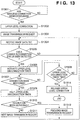
- the application unit 207 Upon receiving a notification indicating that the wireless connection has been disconnected from the radio data transmitter/receiver 203, the application unit 207 determines that the status of wireless connection has been changed, and advances the procedure from step S1305 to step S1306. In step S1306, the application unit 207 activates the upper level disconnection timer. When the application unit 207 receives a notification indicating that the wireless connection has been connected from the radio data transmitter/receiver 203 before the upper level disconnection timer times out, the application unit 207 determines that the wireless connection has been restored, and advances the procedure from step S1307 to step S1309, where the application unit 207 halts the upper level disconnection timer.
- step S1310 the application unit 207 determines whether or not a particular button of the PJ 201 has been depressed based on the reception or non-reception of a notification from the status determination unit 205.
- the application unit 207 transmits a next image transmission request that requests the transmission of the next image data file to the DSC 101 via the radio data transmitter/receiver 203.
- the application unit 207 transmits a previous image transmission request that requests the transmission of the previous image data file to the DSC 101 via the radio data transmitter/receiver 203.
- step S1304 the application unit 207 receives the image data file from the DSC 101 via the radio data transmitter/receiver 203.
- the procedure advances from step S1308 to step S1314, where the application unit 207 releases the upper level connection and ends the process.
- the application unit 107 of the DSC 101 transmits an image data file in response to an image transmission request, a previous image transmission request or a next image transmission request from the PJ 201.
- the operation performed by the application unit 107 of the DSC 101 is not shown in a flowchart because it is clear from the sequence diagrams of FIGS. 5 , 6 and 8 .
- connection/disconnection by the short range wireless transfer technique in the wireless image output system of the present invention was described, but the wireless communication that can be used is not limited thereto, and for example, it is possible to use the connection/disconnection by a wireless technique such as Bluetooth® or NFC.
- the timing at which the next image/previous image is designated as an image to be transferred is after the DSC 101 and the wireless port 202 are again brought close to each other, but it can be when the connection is disconnected before they are again brought close to each other.
- a configuration may be adopted in which the image to be requested when the DSC 101 and the wireless port 202 are again brought close to each other can be set to either the next image or the previous image according to the time during which the DSC 101 is placed on the wireless port 202.
- an instruction to select the previous image data file or the next image data file is made by performing a connection process while a button is depressed, but the present invention is not limited thereto, and the button operation can be replaced by a configuration capable of recognizing a change in the status using a sensor or the like such as, for example, bringing the DSC 101 close to the wireless port 202 with the DSC 101 being overturned, or brining the DSC 101 close to the wireless port 202 with increased acceleration.
- Embodiments 1 and 2 in order to select a data file to be transferred, disconnection and restoration of wireless connection are utilized as changes in the status of wireless connection, but the present invention is not limited thereto.
- Embodiment 3 a configuration will be described in which an image data file to be transferred is changed according to the electric field intensity of a short range wireless transfer technique as a change in the status of wireless connection.
- the configurations of a DSC 101, a PJ 201 and a data communication system according to Embodiment 3 are the same as those of Embodiment 1 described above ( FIGS. 1 to 3 ).
- an operation according to Embodiment 3 will be described with reference to FIGS. 5 , 6 and 9 .
- Embodiment 2 The operation performed by the user to project the image data being displayed on the display unit 105 of the DSC 101 with the PJ 201 was described in Embodiment 2 ( FIG. 5 ), so a description thereof is omitted here. It is assumed in Embodiment 3 that the distance between the DSC 101 and the wireless port 202 is changed within the range in which the wireless connection is not disconnected, and an electric field intensity threshold value used to determine whether the DSC 101 is close to or far from the wireless port 202 is set in advance in the PJ 201.
- an electric field intensity value is notified by the wireless port 202, and is received by the application unit 207 of the PJ 201 (S902).
- the timing at which the electric field intensity value is notified can be set to any timing such as a specified interval or when there is a change in the status.
- the status determination unit 205 of the PJ 201 compares the notified electric field intensity value with the preset threshold value.
- a status ("weak") change message is transmitted from the application unit 207 of the PJ 201 to the radio data transmitter/receiver 203 of the wireless port 202 (S904).
- the message is transmitted from the PJ 201 via the radio data transmitter/receivers 203 and 102 (S905) to the application unit 107 of the DSC 101 (S906) by the short range wireless transfer technique.
- the application unit 107 of the DSC 101 that has received the status ("weak") change message transmits a response message to the application unit 207 of the PJ 201 (S907 to S909).
- Each of the application units 107 and 207 changes their respective status, and activates their respective upper level disconnection timer.
- the value of the timer may be a fixed value set by the apparatus, or may be a value set by the user.
- the PJ 201 stops the projection of the image.
- the status determination unit 205 of the PJ 201 again compares the electric field intensity value with the threshold value.
- the electric field intensity value is higher than the threshold value (S912), in order to change the status of the image output system, a status ("strong") change message is transmitted from the application unit 207 of the PJ 201 to the radio data transmitter/receiver 203 of the wireless port 202 (S913).
- the message is transmitted via the radio data transmitter/receiver 102 of the DSC 101 (S914) to the application unit 107 of the DSC 101 (S915) by the short range wireless transfer technique.
- the application unit 107 of the DSC 101 that has received the status ("strong") change message transmits a response message to the application unit 207 of the PJ 201 (S916 to S918). Thereby, each of the application units 107 and 207 changes their respective status, and halts the upper level disconnection timer.
- the application unit 207 of the PJ 201 that has received the status ("strong") change message issues a request to transfer the next image data file (S919 to S921).
- the application unit 107 of the DSC 101 that has received the request to transfer the next image data file transfers the image data file from the storage unit 106 to the radio data transmitter/receiver 102 (S922).
- the image data file transferred via the radio data transmitter/receiver 203 of the wireless port 202 (S923) to the application unit 207 of the PJ 201 (S924) by the short range wireless transfer technique is projected onto the screen 301 by the image output unit 204 (S925).
- the image data file that has been transmitted to the PJ 201 is displayed on the display unit 105 of the DSC 101 (S926). It is also possible to adopt a configuration in which the projected image is continuously projected when the status of the PJ 201 is changed to "weak" status.
- step S1305 a change in the connected status is detected when the reception electric field intensity of the wireless connection falls below a preset threshold value.
- step S1307 the restoration of the wireless connection is detected when the reception electric field intensity of the wireless connection reaches or exceeds the preset threshold value.
- the operation of the DSC 101 is clear from the sequence diagrams of FIGS. 5 , 6 and 9 as in Embodiment 2.
- the wireless communication that can be used is not limited thereto, and for example, it is possible to use a wireless technique such as Bluetooth® or NFC.
- the button operation can be replaced by a configuration capable of recognizing a change in the status using a sensor or the like such as, for example, bringing the DSC 101 close to the wireless port 202 with the DSC 101 being overturned, or bringing the DSC 101 close to the wireless port 202 with increased acceleration.
- Embodiments 1 to 3 the selection of an image data file is changed by an operation such as depressing a button.
- the period during which the connected status of wireless connection is maintained is measured, and the selection of an image data file is changed based on the measured period.
- control is performed such that the image data file stored in the PJ 201 is displayed, and an image data file is not transferred from the DSC 101.
- the configurations of a DSC 101, a PJ 201 and a data communication system according to Embodiment 4 are the same as those of Embodiment 1 ( FIGS. 1 to 3 ).
- an operation according to Embodiment 4 will be described with reference to FIGS. 4 , 6 , 10 and 11 .
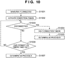
- each apparatus needs to determine whether the connection method is a contact method A or contact method B.
- a process for determining such a contact method will be described with reference to the flowchart of FIG. 10 .
- the application units 107 and 207 detect that the wireless connection has been established by a notification from the radio data transmitter/receivers 102 and 203, respectively (S1001). Upon detecting the establishment of the wireless connection, the application units 107 and 207 of the apparatuses each activate a connection timer that monitors the time during which the connection is maintained (S1002). It is assumed that the apparatuses have a common time out value. When the connection is disconnected before the connection timers time out (S1003), the application units 107 and 207 of the apparatuses halt the connection timers (S1004) and determine that the wireless connection was a contact process B (S1005).
- the application units 107 and 207 of the apparatuses determine that the wireless connection was a contact process A (S1007). At this time, it is also possible to adopt a configuration in which the time out value can be set by the user in advance.
- Embodiment 1 The operation performed by the user to project the image data being displayed on the display unit 105 of the DSC 101 with the PJ 201 was described in Embodiment 1 ( FIG. 4 ), so a description thereof is omitted here.
- the wireless connection is set to a contact process A by the user maintaining the connected status of the wireless connection until the connection timers time out (S1007 of FIG. 10 ).
- the user moves the DSC 101, which was close to the wireless port 202, away from the wireless port 202 (S1101).
- the DSC 101 and the PJ 201 enter a disconnected status by the short range wireless transfer technique (S1102).
- the disconnected status is notified to each of the application units 107 and 207 (S1103, S1104).
- Each of the application units 107 and 207 that has received the notification activates their respective upper level disconnection timer.
- the value of the timer may be configured to be preset in the apparatus, or set by the user.
- the PJ 201 stops the projection of the image.
- the DSC 101 and the PJ 201 again enter a connected status (S1106).
- the radio data transmitter/receivers 102 and 203 notify the application units 107 and 207, respectively, of the wireless connection (S1106a, S1106b).
- Each of the application units 107 and 207 determines the contact process (S1107, S1108), and halts their respective upper level disconnection timer.
- the application unit 107 of the DSC 101 that has determined that the connection was the contact process A transfers the next image data file from the storage unit 106 to the application unit 207 of the PJ 201 (S1109 to S1112).
- the next image data file transferred to the application unit 207 of the PJ 201 is projected onto the screen 301 by the image output unit 204 (S1113), and stored in the storage unit (206) of the PJ 201 (S1114).
- the image data file that has been transmitted to the PJ 201 is displayed on the display unit 105 of the DSC 101 (S1115). It is also possible to adopt a configuration in which the projected image is continuously projected in the disconnected status.
- the DSC 101 which was close to the wireless port 202, is moved away from the wireless port 202 (S1116). Then, the DSC 101 and the PJ 201 enter a disconnected status by the short range wireless transfer technique (S1117). Within the respective apparatuses, the disconnected status is notified to the application units 107 and 207 (S1118, S1119). Each of the application units 107 and 207 that has received the notification activates an upper level disconnection timer, and the PJ 201 stops the projection of the image.
- the DSC 101 and the PJ 201 again enter a connected status (S1121).
- the radio data transmitter/receivers 102 and 203 notify the application units 107 and 207, respectively, of the wireless connection (S1121a, S1121b).
- Each of the application units 107 and 207 determines the contact process (S1123, S1124), and halts their respective upper level disconnection timer.
- a wireless connection notification and a wireless disconnection notification are not shown, but it is also possible to adopt a configuration in which such notifications are issued.
- the application unit 207 of the PJ 201 that has determined that the connection was the contact process B reads the previous image data file from the storage unit 206 (S1125), and the previous image data file is projected onto the screen 301 by the image output unit 204 (S1126).
- Embodiment 4 when the PJ 201 displays a previous image data file that has already been transmitted, the image data file stored in the PJ 201 is displayed, and the transfer of an image data file from the DSC 101 is prohibited. Accordingly, unnecessary transfer of an image data file between the DSC 101 and the PJ 201 can be eliminated.
- the operation of transferring a different image data file from the previous image data file under control of the DSC according to the connection/disconnection by the short range wireless transfer technique in the wireless image output system of the present invention was described, but the wireless communication that can be used is not limited thereto, and for example, it is possible to use the connection/disconnection by a wireless technique such as Bluetooth® or NFC.
- Embodiment 4 a configuration is adopted in which a connection timer is provided to each of the DSC 101 and the PJ 201, each apparatus determines a contact process (wireless connection status) type, and when displaying a previous image data file, the PJ 201 obtains the data from the storage unit 206 of the PJ 201.
- the use of the wireless connection status type is not limited thereto, and it is possible to, for example, use the wireless connection status type instead of depressing a button when the connection is restored according to Embodiments 1 and 2.
- the branches in the process of step S1209 of FIG. 12 may be performed with the wireless connection status type determined in the process of FIG. 10 .
- the branches in the process of step S1306 of FIG. 13 may be performed with the wireless connection status type.
- the wireless connection status type is not limited to those shown in the above embodiment.
- the present invention is also achievable in embodiments such as a system, an apparatus, a method, a program, or a storage medium. Specifically, it may also be applied to a system constituted by multiple devices and may also be applied to an apparatus constituted by a single device.
- the supplied program is a computer program that corresponds to the flowchart indicated in the drawings in the embodiment.
- the program code itself installed in a computer so as to realize the functional processing of the present invention through a computer, also realizes the present invention.
- the computer program itself for realizing the functional processing of the present invention, is also included within the scope of the present invention.
- object code a program executed through an interpreter, script data supplied to an OS, or the like may be used, as long as it has the functions of the program.
- Examples of the a computer readable storage medium that can be used to supply the computer program include Floppy® disks, hard disks, optical disks, magneto-optical disks, MOs, CD-ROMs, CD-Rs, CD-RWs, magnetic tape, non-volatile memory cards, ROMs, and DVDs (DVD-ROMs, DVD-Rs).
- a browser of a client computer to connect to an Internet homepage and downloading the computer program of the present invention to a storage medium such as a hard disk can be given as another method for supplying the program.
- the downloaded program may be a compressed file including a function for automatic installation.
- this method may be realized by dividing the program code that makes up the program of the present invention into a plurality of files and downloading each file from different homepages.
- a WWW server that allows a plurality of users to download the program files for realizing the functional processing of the present invention through a computer also falls within the scope of the present invention.
- the program of the present invention may be encrypted, stored in a storage medium such as a CD-ROM, and distributed to users.
- a user that has cleared a predetermined condition is allowed to download key information for removing the cryptography from a homepage via the Internet, use the key information to decrypt the program, and install the program on a computer.
- the functions of the present embodiment may be realized, in addition to through the execution of a loaded program using a computer, through cooperation with an OS or the like running on the computer based on instructions of the program.
- the OS or the like performs part or all of the actual processing, and the functions of the above-described embodiment are realized by that processing.
- part or all of the functionality of the aforementioned embodiment may be written into a memory provided in a function expansion board installed in the computer, a function expansion unit connected to the computer, or the like, into which the program read out from the storage medium is written.
- a CPU or the like included in the function expansion board or the function expansion unit performs part or all of the actual processing based on the instructions of the program.
Landscapes
- Engineering & Computer Science (AREA)
- Signal Processing (AREA)
- Multimedia (AREA)
- Computer Networks & Wireless Communication (AREA)
- Environmental & Geological Engineering (AREA)
- Facsimiles In General (AREA)
- Mobile Radio Communication Systems (AREA)
- Studio Devices (AREA)
- Controls And Circuits For Display Device (AREA)
- Closed-Circuit Television Systems (AREA)
Priority Applications (1)
| Application Number | Priority Date | Filing Date | Title |
|---|---|---|---|
| EP16195008.4A EP3151443A1 (en) | 2008-06-30 | 2009-06-02 | Data supplying apparatus, data processing apparatus and data communication system |
Applications Claiming Priority (2)
| Application Number | Priority Date | Filing Date | Title |
|---|---|---|---|
| JP2008171243A JP5171436B2 (ja) | 2008-06-30 | 2008-06-30 | 通信装置、データ通信システム、通信装置の制御方法及びプログラム |
| PCT/JP2009/060409 WO2010001688A1 (en) | 2008-06-30 | 2009-06-02 | Data supplying apparatus, data processing apparatus and data communication system |
Related Child Applications (2)
| Application Number | Title | Priority Date | Filing Date |
|---|---|---|---|
| EP16195008.4A Division-Into EP3151443A1 (en) | 2008-06-30 | 2009-06-02 | Data supplying apparatus, data processing apparatus and data communication system |
| EP16195008.4A Division EP3151443A1 (en) | 2008-06-30 | 2009-06-02 | Data supplying apparatus, data processing apparatus and data communication system |
Publications (3)
| Publication Number | Publication Date |
|---|---|
| EP2294702A1 EP2294702A1 (en) | 2011-03-16 |
| EP2294702A4 EP2294702A4 (en) | 2012-01-04 |
| EP2294702B1 true EP2294702B1 (en) | 2016-12-21 |
Family
ID=41465791
Family Applications (2)
| Application Number | Title | Priority Date | Filing Date |
|---|---|---|---|
| EP09773266.3A Not-in-force EP2294702B1 (en) | 2008-06-30 | 2009-06-02 | Data supplying apparatus, data processing apparatus and data communication system |
| EP16195008.4A Withdrawn EP3151443A1 (en) | 2008-06-30 | 2009-06-02 | Data supplying apparatus, data processing apparatus and data communication system |
Family Applications After (1)
| Application Number | Title | Priority Date | Filing Date |
|---|---|---|---|
| EP16195008.4A Withdrawn EP3151443A1 (en) | 2008-06-30 | 2009-06-02 | Data supplying apparatus, data processing apparatus and data communication system |
Country Status (5)
| Country | Link |
|---|---|
| US (2) | US8792829B2 (https=) |
| EP (2) | EP2294702B1 (https=) |
| JP (1) | JP5171436B2 (https=) |
| CN (2) | CN102077478B (https=) |
| WO (1) | WO2010001688A1 (https=) |
Families Citing this family (10)
| Publication number | Priority date | Publication date | Assignee | Title |
|---|---|---|---|---|
| JP5069722B2 (ja) | 2009-06-19 | 2012-11-07 | 株式会社エヌ・ティ・ティ・ドコモ | 移動通信端末、及びデータダウンロード方法 |
| JP5743675B2 (ja) * | 2010-05-13 | 2015-07-01 | キヤノン株式会社 | 通信装置、通信装置の制御方法およびプログラム。 |
| US9189511B2 (en) * | 2011-09-07 | 2015-11-17 | Unisys Corporation | Free resources parameter for improving performance of database alterations |
| JP5968108B2 (ja) * | 2012-06-20 | 2016-08-10 | キヤノン株式会社 | 通信装置 |
| WO2014046424A1 (en) * | 2012-09-18 | 2014-03-27 | Samsung Electronics Co., Ltd. | Information transmission method and system, and device |
| TW201501519A (zh) * | 2013-06-21 | 2015-01-01 | Ability Entpr Co Ltd | 攝像裝置與影像串流輸出方法 |
| CN104253932A (zh) * | 2013-06-26 | 2014-12-31 | 佳能企业股份有限公司 | 摄像装置与影像流媒体输出方法 |
| CN103747242B (zh) * | 2013-12-23 | 2016-05-11 | 乐视致新电子科技(天津)有限公司 | 一种自动检测摄像设备的方法和检测设备 |
| US10602046B2 (en) * | 2017-07-11 | 2020-03-24 | Htc Corporation | Mobile device and control method |
| JP7033978B2 (ja) * | 2018-03-28 | 2022-03-11 | 株式会社トプコン | 測量機の遠隔操作システム |
Citations (2)
| Publication number | Priority date | Publication date | Assignee | Title |
|---|---|---|---|---|
| EP1538819A1 (en) * | 2002-09-12 | 2005-06-08 | Sony Corporation | Information communication system, information communication device, information communication method, and computer program |
| US7236755B2 (en) * | 2003-04-02 | 2007-06-26 | Matsushita Electric Industrial Co., Ltd. | Broadcast wave receiving apparatus |
Family Cites Families (22)
| Publication number | Priority date | Publication date | Assignee | Title |
|---|---|---|---|---|
| JP3384636B2 (ja) * | 1995-01-19 | 2003-03-10 | 三洋電機株式会社 | 画像通信装置 |
| JP2000209653A (ja) * | 1999-01-18 | 2000-07-28 | Kobe Steel Ltd | 無線電話装置 |
| JP2001325182A (ja) * | 2000-03-10 | 2001-11-22 | Ricoh Co Ltd | 印刷システム、印刷方法及びプログラムを記録したコンピュータ読取可能な記録媒体並びに該印刷システムにおける携帯通信機器、プリンタ、プリントサーバー及びクライアント |
| JP2001282424A (ja) | 2000-03-29 | 2001-10-12 | Seiko Epson Corp | プレゼンテーションシステム及びワイヤレスリモコン |
| DE60210499T2 (de) * | 2001-11-01 | 2006-11-16 | Sony Corp. | Informationsverarbeitungsendgerät und -verfahren für ein drahtlossystem |
| US6957232B2 (en) * | 2002-04-05 | 2005-10-18 | Infocus Corporation | Projector control markup language |
| KR20040016058A (ko) | 2002-08-14 | 2004-02-21 | 엘지전자 주식회사 | 마우스 기능을 구비한 포인팅 시스템 |
| JP2004128673A (ja) * | 2002-09-30 | 2004-04-22 | Toshiba Corp | 電子機器およびコンテンツ再生方法 |
| JP4343524B2 (ja) | 2002-12-13 | 2009-10-14 | キヤノン株式会社 | 制御装置およびデジタルビデオ装置 |
| JP2004240825A (ja) * | 2003-02-07 | 2004-08-26 | Toshiba Corp | 情報処理装置および画像データ送信制御方法 |
| CN101095127B (zh) * | 2003-06-02 | 2014-04-09 | 精工爱普生株式会社 | 通过网络通告图像显示设备的存在的方法 |
| KR100524588B1 (ko) * | 2003-06-19 | 2005-10-31 | 에스케이 텔레콤주식회사 | 무선인터넷에서 다운로드 중단된 데이터를 이어받는 방법 |
| JP2005223518A (ja) | 2004-02-04 | 2005-08-18 | Seiko Epson Corp | 画像供給装置、画像保存装置、自動保存システムおよび画像保存方法 |
| TWI289389B (en) * | 2004-12-15 | 2007-11-01 | Univ Tsinghua | Roaming system and method for heterogeneous wireless network environment |
| US7616594B2 (en) * | 2005-04-22 | 2009-11-10 | Microsoft Corporation | Wireless device discovery and configuration |
| CN2850076Y (zh) * | 2005-09-06 | 2006-12-20 | 万家盛 | 一种电气盒 |
| JP2007184858A (ja) * | 2006-01-10 | 2007-07-19 | Seiko Epson Corp | 画像表示システム |
| US9489109B2 (en) * | 2006-03-30 | 2016-11-08 | Sony Ericsson Mobile Communication Ab | Data communication in an electronic device |
| JP2008041225A (ja) * | 2006-08-10 | 2008-02-21 | Alpine Electronics Inc | オーディオ/ビデオ再生装置、オーディオ/ビデオシステム及び更新情報通知方法 |
| JP2008171243A (ja) | 2007-01-12 | 2008-07-24 | Fujifilm Corp | コンテンツ検索装置および方法並びにプログラム |
| JP4513029B2 (ja) * | 2007-03-09 | 2010-07-28 | 株式会社東芝 | 情報処理装置 |
| JP5075032B2 (ja) | 2008-06-30 | 2012-11-14 | キヤノン株式会社 | 通信装置及び通信方法 |
-
2008
- 2008-06-30 JP JP2008171243A patent/JP5171436B2/ja not_active Expired - Fee Related
-
2009
- 2009-06-02 WO PCT/JP2009/060409 patent/WO2010001688A1/en not_active Ceased
- 2009-06-02 EP EP09773266.3A patent/EP2294702B1/en not_active Not-in-force
- 2009-06-02 CN CN200980125323.0A patent/CN102077478B/zh active Active
- 2009-06-02 EP EP16195008.4A patent/EP3151443A1/en not_active Withdrawn
- 2009-06-02 CN CN201610529801.6A patent/CN106100933B/zh active Active
- 2009-06-02 US US12/988,629 patent/US8792829B2/en active Active
-
2014
- 2014-07-28 US US14/444,815 patent/US9237413B2/en active Active
Patent Citations (2)
| Publication number | Priority date | Publication date | Assignee | Title |
|---|---|---|---|---|
| EP1538819A1 (en) * | 2002-09-12 | 2005-06-08 | Sony Corporation | Information communication system, information communication device, information communication method, and computer program |
| US7236755B2 (en) * | 2003-04-02 | 2007-06-26 | Matsushita Electric Industrial Co., Ltd. | Broadcast wave receiving apparatus |
Also Published As
| Publication number | Publication date |
|---|---|
| WO2010001688A1 (en) | 2010-01-07 |
| EP2294702A4 (en) | 2012-01-04 |
| JP2010011365A (ja) | 2010-01-14 |
| EP2294702A1 (en) | 2011-03-16 |
| CN106100933A (zh) | 2016-11-09 |
| US8792829B2 (en) | 2014-07-29 |
| US20110053508A1 (en) | 2011-03-03 |
| CN102077478A (zh) | 2011-05-25 |
| EP3151443A1 (en) | 2017-04-05 |
| US20140335786A1 (en) | 2014-11-13 |
| US9237413B2 (en) | 2016-01-12 |
| JP5171436B2 (ja) | 2013-03-27 |
| CN106100933B (zh) | 2020-02-28 |
| CN102077478B (zh) | 2016-08-03 |
Similar Documents
| Publication | Publication Date | Title |
|---|---|---|
| EP2294702B1 (en) | Data supplying apparatus, data processing apparatus and data communication system | |
| CN107800955B (zh) | 通信装置、通信装置的控制方法和存储介质 | |
| EP2833653B1 (en) | Method and apparatus for establishing communication between an image photographing apparatus and a user device | |
| EP2308223B1 (en) | Data output apparatus, method of controlling same and output system | |
| JP6914746B2 (ja) | 送電装置、送電装置の制御方法、プログラム | |
| JP6858069B2 (ja) | 画像供給装置及び情報処理装置及びそれらの制御方法とプログラム | |
| JP6882055B2 (ja) | 通信装置及びその制御方法及びプログラム及び通信システム | |
| CN110278589B (zh) | 通信装置、数据传输装置及其控制方法和存储介质 | |
| JP6385078B2 (ja) | 通信装置、通信装置の制御方法、プログラム | |
| JP6319234B2 (ja) | 遠隔制御システム、画像処理装置、遠隔制御方法、および遠隔制御プログラム | |
| JP4834348B2 (ja) | 無線通信装置及び無線通信方法 | |
| JP5568120B2 (ja) | 通信装置およびその制御方法、プログラム | |
| US10084952B2 (en) | Communication apparatus wirelessly communicating with external apparatus, control method of communication apparatus, and storage medium | |
| JP2017092645A (ja) | 無線通信システム、情報処理方法及びプログラム | |
| JP2019062260A (ja) | 被制御装置、通信制御方法、及びプログラム | |
| JP6869656B2 (ja) | 送信装置、受信装置、及び、通信システム | |
| JP6632328B2 (ja) | 制御装置、電力伝送装置、制御方法及びプログラム | |
| JP2016081450A (ja) | 通信装置、通信装置の制御方法及びコンピュータプログラム | |
| JP2015146522A (ja) | 撮像装置、その制御方法及びプログラム | |
| JP5546309B2 (ja) | 通信装置、通信装置の制御方法およびプログラム | |
| JP2020057899A (ja) | 無線通信システム、無線通信端末の制御方法 | |
| JP2018082488A (ja) | 撮像装置、外部機器、それらの制御方法 | |
| JP2019033345A (ja) | 通信装置、その制御方法及びプログラム | |
| JP2017204039A (ja) | 印刷システム、印刷装置、画像取得装置、印刷方法、及びプログラム | |
| JP6559022B2 (ja) | 通信装置、通信装置の制御方法、コンピュータプログラム |
Legal Events
| Date | Code | Title | Description |
|---|---|---|---|
| PUAI | Public reference made under article 153(3) epc to a published international application that has entered the european phase |
Free format text: ORIGINAL CODE: 0009012 |
|
| 17P | Request for examination filed |
Effective date: 20110131 |
|
| AK | Designated contracting states |
Kind code of ref document: A1 Designated state(s): AT BE BG CH CY CZ DE DK EE ES FI FR GB GR HR HU IE IS IT LI LT LU LV MC MK MT NL NO PL PT RO SE SI SK TR |
|
| AX | Request for extension of the european patent |
Extension state: AL BA RS |
|
| DAX | Request for extension of the european patent (deleted) | ||
| A4 | Supplementary search report drawn up and despatched |
Effective date: 20111205 |
|
| RIC1 | Information provided on ipc code assigned before grant |
Ipc: H04L 12/24 20060101ALI20111129BHEP Ipc: H04N 1/00 20060101ALI20111129BHEP Ipc: H04N 5/765 20060101ALI20111129BHEP Ipc: H04W 84/10 20090101ALI20111129BHEP Ipc: H04B 5/02 20060101ALI20111129BHEP Ipc: H04B 1/59 20060101AFI20111129BHEP Ipc: H04W 76/02 20090101ALI20111129BHEP Ipc: H04N 5/775 20060101ALN20111129BHEP Ipc: H04L 12/26 20060101ALN20111129BHEP |
|
| 17Q | First examination report despatched |
Effective date: 20130304 |
|
| GRAP | Despatch of communication of intention to grant a patent |
Free format text: ORIGINAL CODE: EPIDOSNIGR1 |
|
| INTG | Intention to grant announced |
Effective date: 20160629 |
|
| GRAS | Grant fee paid |
Free format text: ORIGINAL CODE: EPIDOSNIGR3 |
|
| GRAA | (expected) grant |
Free format text: ORIGINAL CODE: 0009210 |
|
| AK | Designated contracting states |
Kind code of ref document: B1 Designated state(s): AT BE BG CH CY CZ DE DK EE ES FI FR GB GR HR HU IE IS IT LI LT LU LV MC MK MT NL NO PL PT RO SE SI SK TR |
|
| REG | Reference to a national code |
Ref country code: GB Ref legal event code: FG4D |
|
| REG | Reference to a national code |
Ref country code: CH Ref legal event code: EP |
|
| REG | Reference to a national code |
Ref country code: IE Ref legal event code: FG4D |
|
| REG | Reference to a national code |
Ref country code: FR Ref legal event code: PLFP Year of fee payment: 9 |
|
| REG | Reference to a national code |
Ref country code: AT Ref legal event code: REF Ref document number: 856272 Country of ref document: AT Kind code of ref document: T Effective date: 20170115 |
|
| REG | Reference to a national code |
Ref country code: DE Ref legal event code: R096 Ref document number: 602009043256 Country of ref document: DE |
|
| PG25 | Lapsed in a contracting state [announced via postgrant information from national office to epo] |
Ref country code: LV Free format text: LAPSE BECAUSE OF FAILURE TO SUBMIT A TRANSLATION OF THE DESCRIPTION OR TO PAY THE FEE WITHIN THE PRESCRIBED TIME-LIMIT Effective date: 20161221 |
|
| REG | Reference to a national code |
Ref country code: LT Ref legal event code: MG4D |
|
| REG | Reference to a national code |
Ref country code: NL Ref legal event code: MP Effective date: 20161221 |
|
| PG25 | Lapsed in a contracting state [announced via postgrant information from national office to epo] |
Ref country code: LT Free format text: LAPSE BECAUSE OF FAILURE TO SUBMIT A TRANSLATION OF THE DESCRIPTION OR TO PAY THE FEE WITHIN THE PRESCRIBED TIME-LIMIT Effective date: 20161221 Ref country code: GR Free format text: LAPSE BECAUSE OF FAILURE TO SUBMIT A TRANSLATION OF THE DESCRIPTION OR TO PAY THE FEE WITHIN THE PRESCRIBED TIME-LIMIT Effective date: 20170322 Ref country code: NO Free format text: LAPSE BECAUSE OF FAILURE TO SUBMIT A TRANSLATION OF THE DESCRIPTION OR TO PAY THE FEE WITHIN THE PRESCRIBED TIME-LIMIT Effective date: 20170321 Ref country code: SE Free format text: LAPSE BECAUSE OF FAILURE TO SUBMIT A TRANSLATION OF THE DESCRIPTION OR TO PAY THE FEE WITHIN THE PRESCRIBED TIME-LIMIT Effective date: 20161221 |
|
| REG | Reference to a national code |
Ref country code: AT Ref legal event code: MK05 Ref document number: 856272 Country of ref document: AT Kind code of ref document: T Effective date: 20161221 |
|
| PG25 | Lapsed in a contracting state [announced via postgrant information from national office to epo] |
Ref country code: HR Free format text: LAPSE BECAUSE OF FAILURE TO SUBMIT A TRANSLATION OF THE DESCRIPTION OR TO PAY THE FEE WITHIN THE PRESCRIBED TIME-LIMIT Effective date: 20161221 Ref country code: FI Free format text: LAPSE BECAUSE OF FAILURE TO SUBMIT A TRANSLATION OF THE DESCRIPTION OR TO PAY THE FEE WITHIN THE PRESCRIBED TIME-LIMIT Effective date: 20161221 |
|
| PG25 | Lapsed in a contracting state [announced via postgrant information from national office to epo] |
Ref country code: NL Free format text: LAPSE BECAUSE OF FAILURE TO SUBMIT A TRANSLATION OF THE DESCRIPTION OR TO PAY THE FEE WITHIN THE PRESCRIBED TIME-LIMIT Effective date: 20161221 |
|
| PG25 | Lapsed in a contracting state [announced via postgrant information from national office to epo] |
Ref country code: SK Free format text: LAPSE BECAUSE OF FAILURE TO SUBMIT A TRANSLATION OF THE DESCRIPTION OR TO PAY THE FEE WITHIN THE PRESCRIBED TIME-LIMIT Effective date: 20161221 Ref country code: RO Free format text: LAPSE BECAUSE OF FAILURE TO SUBMIT A TRANSLATION OF THE DESCRIPTION OR TO PAY THE FEE WITHIN THE PRESCRIBED TIME-LIMIT Effective date: 20161221 Ref country code: EE Free format text: LAPSE BECAUSE OF FAILURE TO SUBMIT A TRANSLATION OF THE DESCRIPTION OR TO PAY THE FEE WITHIN THE PRESCRIBED TIME-LIMIT Effective date: 20161221 Ref country code: CZ Free format text: LAPSE BECAUSE OF FAILURE TO SUBMIT A TRANSLATION OF THE DESCRIPTION OR TO PAY THE FEE WITHIN THE PRESCRIBED TIME-LIMIT Effective date: 20161221 Ref country code: IS Free format text: LAPSE BECAUSE OF FAILURE TO SUBMIT A TRANSLATION OF THE DESCRIPTION OR TO PAY THE FEE WITHIN THE PRESCRIBED TIME-LIMIT Effective date: 20170421 |
|
| PG25 | Lapsed in a contracting state [announced via postgrant information from national office to epo] |
Ref country code: AT Free format text: LAPSE BECAUSE OF FAILURE TO SUBMIT A TRANSLATION OF THE DESCRIPTION OR TO PAY THE FEE WITHIN THE PRESCRIBED TIME-LIMIT Effective date: 20161221 Ref country code: PL Free format text: LAPSE BECAUSE OF FAILURE TO SUBMIT A TRANSLATION OF THE DESCRIPTION OR TO PAY THE FEE WITHIN THE PRESCRIBED TIME-LIMIT Effective date: 20161221 Ref country code: BG Free format text: LAPSE BECAUSE OF FAILURE TO SUBMIT A TRANSLATION OF THE DESCRIPTION OR TO PAY THE FEE WITHIN THE PRESCRIBED TIME-LIMIT Effective date: 20170321 Ref country code: IT Free format text: LAPSE BECAUSE OF FAILURE TO SUBMIT A TRANSLATION OF THE DESCRIPTION OR TO PAY THE FEE WITHIN THE PRESCRIBED TIME-LIMIT Effective date: 20161221 Ref country code: PT Free format text: LAPSE BECAUSE OF FAILURE TO SUBMIT A TRANSLATION OF THE DESCRIPTION OR TO PAY THE FEE WITHIN THE PRESCRIBED TIME-LIMIT Effective date: 20170421 Ref country code: ES Free format text: LAPSE BECAUSE OF FAILURE TO SUBMIT A TRANSLATION OF THE DESCRIPTION OR TO PAY THE FEE WITHIN THE PRESCRIBED TIME-LIMIT Effective date: 20161221 Ref country code: BE Free format text: LAPSE BECAUSE OF FAILURE TO SUBMIT A TRANSLATION OF THE DESCRIPTION OR TO PAY THE FEE WITHIN THE PRESCRIBED TIME-LIMIT Effective date: 20161221 |
|
| REG | Reference to a national code |
Ref country code: DE Ref legal event code: R097 Ref document number: 602009043256 Country of ref document: DE |
|
| PLBE | No opposition filed within time limit |
Free format text: ORIGINAL CODE: 0009261 |
|
| STAA | Information on the status of an ep patent application or granted ep patent |
Free format text: STATUS: NO OPPOSITION FILED WITHIN TIME LIMIT |
|
| 26N | No opposition filed |
Effective date: 20170922 |
|
| PG25 | Lapsed in a contracting state [announced via postgrant information from national office to epo] |
Ref country code: DK Free format text: LAPSE BECAUSE OF FAILURE TO SUBMIT A TRANSLATION OF THE DESCRIPTION OR TO PAY THE FEE WITHIN THE PRESCRIBED TIME-LIMIT Effective date: 20161221 |
|
| PG25 | Lapsed in a contracting state [announced via postgrant information from national office to epo] |
Ref country code: MC Free format text: LAPSE BECAUSE OF FAILURE TO SUBMIT A TRANSLATION OF THE DESCRIPTION OR TO PAY THE FEE WITHIN THE PRESCRIBED TIME-LIMIT Effective date: 20161221 |
|
| REG | Reference to a national code |
Ref country code: CH Ref legal event code: PL |
|
| PG25 | Lapsed in a contracting state [announced via postgrant information from national office to epo] |
Ref country code: SI Free format text: LAPSE BECAUSE OF FAILURE TO SUBMIT A TRANSLATION OF THE DESCRIPTION OR TO PAY THE FEE WITHIN THE PRESCRIBED TIME-LIMIT Effective date: 20161221 |
|
| REG | Reference to a national code |
Ref country code: IE Ref legal event code: MM4A |
|
| PG25 | Lapsed in a contracting state [announced via postgrant information from national office to epo] |
Ref country code: LU Free format text: LAPSE BECAUSE OF NON-PAYMENT OF DUE FEES Effective date: 20170602 Ref country code: IE Free format text: LAPSE BECAUSE OF NON-PAYMENT OF DUE FEES Effective date: 20170602 Ref country code: LI Free format text: LAPSE BECAUSE OF NON-PAYMENT OF DUE FEES Effective date: 20170630 Ref country code: CH Free format text: LAPSE BECAUSE OF NON-PAYMENT OF DUE FEES Effective date: 20170630 |
|
| REG | Reference to a national code |
Ref country code: FR Ref legal event code: PLFP Year of fee payment: 10 |
|
| PG25 | Lapsed in a contracting state [announced via postgrant information from national office to epo] |
Ref country code: MT Free format text: LAPSE BECAUSE OF NON-PAYMENT OF DUE FEES Effective date: 20170602 |
|
| PG25 | Lapsed in a contracting state [announced via postgrant information from national office to epo] |
Ref country code: HU Free format text: LAPSE BECAUSE OF FAILURE TO SUBMIT A TRANSLATION OF THE DESCRIPTION OR TO PAY THE FEE WITHIN THE PRESCRIBED TIME-LIMIT; INVALID AB INITIO Effective date: 20090602 |
|
| PG25 | Lapsed in a contracting state [announced via postgrant information from national office to epo] |
Ref country code: CY Free format text: LAPSE BECAUSE OF NON-PAYMENT OF DUE FEES Effective date: 20161221 |
|
| PG25 | Lapsed in a contracting state [announced via postgrant information from national office to epo] |
Ref country code: MK Free format text: LAPSE BECAUSE OF FAILURE TO SUBMIT A TRANSLATION OF THE DESCRIPTION OR TO PAY THE FEE WITHIN THE PRESCRIBED TIME-LIMIT Effective date: 20161221 |
|
| PG25 | Lapsed in a contracting state [announced via postgrant information from national office to epo] |
Ref country code: TR Free format text: LAPSE BECAUSE OF FAILURE TO SUBMIT A TRANSLATION OF THE DESCRIPTION OR TO PAY THE FEE WITHIN THE PRESCRIBED TIME-LIMIT Effective date: 20161221 |
|
| PGFP | Annual fee paid to national office [announced via postgrant information from national office to epo] |
Ref country code: GB Payment date: 20240521 Year of fee payment: 16 |
|
| PGFP | Annual fee paid to national office [announced via postgrant information from national office to epo] |
Ref country code: DE Payment date: 20240521 Year of fee payment: 16 |
|
| PGFP | Annual fee paid to national office [announced via postgrant information from national office to epo] |
Ref country code: FR Payment date: 20240522 Year of fee payment: 16 |
|
| REG | Reference to a national code |
Ref country code: DE Ref legal event code: R119 Ref document number: 602009043256 Country of ref document: DE |
|
| GBPC | Gb: european patent ceased through non-payment of renewal fee |
Effective date: 20250602 |
|
| PG25 | Lapsed in a contracting state [announced via postgrant information from national office to epo] |
Ref country code: GB Free format text: LAPSE BECAUSE OF NON-PAYMENT OF DUE FEES Effective date: 20250602 |
|
| PG25 | Lapsed in a contracting state [announced via postgrant information from national office to epo] |
Ref country code: DE Free format text: LAPSE BECAUSE OF NON-PAYMENT OF DUE FEES Effective date: 20260101 |
|
| PG25 | Lapsed in a contracting state [announced via postgrant information from national office to epo] |
Ref country code: FR Free format text: LAPSE BECAUSE OF NON-PAYMENT OF DUE FEES Effective date: 20250630 |