EP2294497B1 - Wärmemanagementtechniken in einer elektronischen anordnung - Google Patents
Wärmemanagementtechniken in einer elektronischen anordnung Download PDFInfo
- Publication number
- EP2294497B1 EP2294497B1 EP09758873.5A EP09758873A EP2294497B1 EP 2294497 B1 EP2294497 B1 EP 2294497B1 EP 09758873 A EP09758873 A EP 09758873A EP 2294497 B1 EP2294497 B1 EP 2294497B1
- Authority
- EP
- European Patent Office
- Prior art keywords
- temperature
- power consumption
- battery
- component
- sensor
- Prior art date
- Legal status (The legal status is an assumption and is not a legal conclusion. Google has not performed a legal analysis and makes no representation as to the accuracy of the status listed.)
- Active
Links
Images




Classifications
-
- G—PHYSICS
- G06—COMPUTING OR CALCULATING; COUNTING
- G06F—ELECTRIC DIGITAL DATA PROCESSING
- G06F1/00—Details not covered by groups G06F3/00 - G06F13/00 and G06F21/00
- G06F1/16—Constructional details or arrangements
- G06F1/20—Cooling means
- G06F1/203—Cooling means for portable computers, e.g. for laptops
-
- G—PHYSICS
- G06—COMPUTING OR CALCULATING; COUNTING
- G06F—ELECTRIC DIGITAL DATA PROCESSING
- G06F1/00—Details not covered by groups G06F3/00 - G06F13/00 and G06F21/00
- G06F1/16—Constructional details or arrangements
- G06F1/20—Cooling means
- G06F1/206—Cooling means comprising thermal management
-
- G—PHYSICS
- G06—COMPUTING OR CALCULATING; COUNTING
- G06F—ELECTRIC DIGITAL DATA PROCESSING
- G06F1/00—Details not covered by groups G06F3/00 - G06F13/00 and G06F21/00
- G06F1/26—Power supply means, e.g. regulation thereof
- G06F1/32—Means for saving power
- G06F1/3203—Power management, i.e. event-based initiation of a power-saving mode
-
- H—ELECTRICITY
- H04—ELECTRIC COMMUNICATION TECHNIQUE
- H04W—WIRELESS COMMUNICATION NETWORKS
- H04W52/00—Power management, e.g. Transmission Power Control [TPC] or power classes
- H04W52/02—Power saving arrangements
- H04W52/0209—Power saving arrangements in terminal devices
- H04W52/0261—Power saving arrangements in terminal devices managing power supply demand, e.g. depending on battery level
- H04W52/0267—Power saving arrangements in terminal devices managing power supply demand, e.g. depending on battery level by controlling user interface components
- H04W52/027—Power saving arrangements in terminal devices managing power supply demand, e.g. depending on battery level by controlling user interface components by controlling a display operation or backlight unit
-
- Y—GENERAL TAGGING OF NEW TECHNOLOGICAL DEVELOPMENTS; GENERAL TAGGING OF CROSS-SECTIONAL TECHNOLOGIES SPANNING OVER SEVERAL SECTIONS OF THE IPC; TECHNICAL SUBJECTS COVERED BY FORMER USPC CROSS-REFERENCE ART COLLECTIONS [XRACs] AND DIGESTS
- Y02—TECHNOLOGIES OR APPLICATIONS FOR MITIGATION OR ADAPTATION AGAINST CLIMATE CHANGE
- Y02D—CLIMATE CHANGE MITIGATION TECHNOLOGIES IN INFORMATION AND COMMUNICATION TECHNOLOGIES [ICT], I.E. INFORMATION AND COMMUNICATION TECHNOLOGIES AIMING AT THE REDUCTION OF THEIR OWN ENERGY USE
- Y02D10/00—Energy efficient computing, e.g. low power processors, power management or thermal management
-
- Y—GENERAL TAGGING OF NEW TECHNOLOGICAL DEVELOPMENTS; GENERAL TAGGING OF CROSS-SECTIONAL TECHNOLOGIES SPANNING OVER SEVERAL SECTIONS OF THE IPC; TECHNICAL SUBJECTS COVERED BY FORMER USPC CROSS-REFERENCE ART COLLECTIONS [XRACs] AND DIGESTS
- Y02—TECHNOLOGIES OR APPLICATIONS FOR MITIGATION OR ADAPTATION AGAINST CLIMATE CHANGE
- Y02D—CLIMATE CHANGE MITIGATION TECHNOLOGIES IN INFORMATION AND COMMUNICATION TECHNOLOGIES [ICT], I.E. INFORMATION AND COMMUNICATION TECHNOLOGIES AIMING AT THE REDUCTION OF THEIR OWN ENERGY USE
- Y02D30/00—Reducing energy consumption in communication networks
- Y02D30/70—Reducing energy consumption in communication networks in wireless communication networks
Definitions
- US 2007/255972 describes a system in which a temperature sensor in a microprocessor monitors its operating temperature
- Operating point data includes a first temperature being the maximum temperature at which the microprocessor will reliably operate at a first frequency and first voltage, the first frequency being the maximum frequency at which the microprocessor will reliably operate at the first temperature and the first voltage.
- Operating point data also includes a second temperature at which the microprocessor will reliably operate at a second frequency and a second voltage, the second frequency being greater than the first frequency and the second temperature less than the first temperature.;
- a control circuit causes the microprocessor to operate at the second voltage and frequency rather than the first voltage and frequency in response to detecting that while operating at the first voltage and the first frequency the operating temperature dropped below the second temperature.
- An embodiment of the invention is directed to an improved thermal management process running in a portable handheld wireless communications device that has relatively confined internal space, to manage the device's own thermal behavior but without significantly impacting the user experience.
- the behavior of the device is managed so that the temperature of the device's battery (or other rechargeable main power source) stays within a given predefined range. See, e.g . Certification Requirements for Battery System Compliance to IEEE 1725, October 2007 , Revision 1.4 (CTIA Certification Program). This is because battery temperature may quickly rise to undesirable levels during even normal operation of the device, e.g. when using a device that has been left inside a parked automobile in the sun, to make a cellular phone call.
- this may be due to the operation of certain power hungry integrated circuit components of the device, such as the RF power amplifier (PA) that drives the device's cellular network RF communications antenna.
- the RF PA often responds to requests from a base station, with which the device is registered, to increase its RF output power if the base station determines that signal from the device is weakening for any reason.
- This together with the normal current drawn by the remaining electrical components, may significantly increase the heat that must be dissipated, due to the electrical power consumption by the RF PA, thereby causing the battery to quickly heat up due to its relative proximity to the RF PA.
- a second thermal arena to monitor and manage in the device is the device's external case temperature.
- This should also be kept in a predefined range, e.g. as specified by Underwriters Laboratories (UL) for consumer grade cellular telephone handsets.
- UL Underwriters Laboratories
- the external case of the device should not become so warm as to become uncomfortable for the user, e.g. while it is being held in the users hand or against the user's ear.
- the external case may be heated by any power consumed within the device, and the hottest points on the external case will most likely be in proximity to the circuitry with the highest concentration of power dissipation. In one embodiment, this may be the RF PA, as in the example above, or it may be another component or group of components, such as the application processor in a mobile telephone or smart phone.
- a given mobile device may include more than one source of heat that individually, or in concert with others, causes either one or both of the battery and the external case temperature to rise above the desired maximum temperature. Also, the inventions described in this document are not limited to managing the temperature of batteries and external cases, but are applicable to any undesirable thermal behavior in the mobile device.
- the process of thermal management needs accurate information about the temperature in various places of the device.
- multiple temperature sensors can be built into the device, and then calibrated before use. These may be in contact with or located near their respective components to be monitored. Temperature readings are "sensed" by such sensors, e.g . by passing a known current through a thermistor during normal operation of the device, measuring its voltage and calculating its resistance.
- a mathematical and/or lookup table relationship is then derived, which is then stored in the device for later use "in the field", i.e. normal operation of the device by the end user or consumer. While in the field, thermal management decisions can be automatically made in the device, e.g. by executing software, based on "effective" temperature readings that have been computed or looked up using the stored relationship, as a function of sensed power consumption measurements.
- heat-generating components of the device that may be automatically controlled, to efficiently improve the thermal behavior of the different arenas (for example, the battery and the external case) of the device.
- One is the cellular network RF transceiver PA whose output RF power can be limited so as to override a contrary request from the cellular base station.
- Another is a central processing unit (CPU), e.g. its microprocessor clock can be throttled down or its power supply voltage may be reduced at the expense of reduced performance.
- CPU central processing unit
- the backlight of the device's main display screen which can be dimmed at the expense of reduced display clarity.
- a "thermal time constant" or thermal decay parameter may be defined for a given component or area of the device. This parameter or function may describe the relationship over time between (1) the temperature of a given component or target area of the device and (2) the temperature of a remote location.
- the thermal time constant takes into account the realization that while the output of a temp sensor could jump to a high value, indicating a fast rise in temperature at that location, the temperature of a remote, target location (that may also be affected by the same increased heat) will rise more slowly ( e.g ., along a substantially different curve). This is illustrated in the example, simulated temperature response graph of Fig. 1 .
- This graph shows the simulated behavior of actual battery temperature (degrees) over time (minutes), responding to a sudden increase in heat that is producing essentially a step response in the raw temperature data output by a sensor that is remote from the battery.
- the graph shows the result of processing the raw temp sensor data using the appropriate thermal time constant, to yield a somewhat exponential-looking curve.
- the processing includes a low pass filtering function that translates an essentially instantaneous change (from some other temperature to 70 degrees) into a much slower change.
- Fig. 1 also illustrates another aspect of thermal behavior in the device, namely that the "steady state" temperatures of the sensor and the target location may be different.
- the processed temp sensor curve is similar in shape to the battery temp curve, but not in absolute value - 70 degrees at the sensor means only 50 degrees at the battery (after about fifteen minutes).
- a further mathematical function derived from the processed temp sensor data and the actual temperature of the target location can be applied to the processed data. Examples of such functions can be seen in equations 1 and 2 described below.
- FIG. 1 depicts a simulated step response
- Fig. 2 shows simulated random heating occurring in the device. Note how the relatively sharp edges of the raw temp sensor curve have been smoothed out by the thermal time constant-based processing.
- Different components of the device may have different-valued thermal time constants or thermal decay parameters, which is a function of how quickly the heat produced by the component can be dissipated by the device.
- the CPU may normally be subjected to its peak power consumption level for a relatively long period of time before its temperature reaches an upper threshold (e.g., several minutes).
- peak RF output power by the cellular network RF transceiver PA can only be sustained for a much shorter period of time (before an upper thermal threshold is reached).
- the thermal time constant of a component may also incorporate the following characteristics: several, relatively frequently occurring and long periods of low power consumption by a component can lead to the same elevated temperature that would result if the component were subjected to fewer and shorter periods of high power consumption. Below are some example time constant parameters for the device 100 described below. TABLE 0 Remote Temperature Sensor Location Time Constant Correlation Temperature (target location) RF Power Amplifier 15 seconds Battery Hot Spot Battery 220 seconds Back Case Center
- the table above gives an example for two remote temperature sensors, one located near the RF PA and another located at the battery (though perhaps not necessarily at the battery's hot spot). There may however be more than two sensors in the device, e.g . another located on-chip with a cellular baseband processor and another located in a different area than all of the others so as to give a better estimate of the ambient temperature inside the device, e.g. near a subscriber identity module, SIM, card circuit.
- SIM subscriber identity module
- a generic thermal management process or system that uses a thermal time constant to compute or estimate the real temperature behavior (over a given time interval) of a target location (the "correlation temperature” in Table 0 above) is now described.
- a temperature of interest e.g. , that of the battery hot spot or the back case center
- output from an associated temperature sensor 201 is processed using the associated thermal time constant.
- the temperature sensor 201 may be a thermistor, or it may be a suitable alternative.
- a digital filter 203 such as a single-pole Infinite Impulse Response (IIR) filter, has a response characterized by a thermal time constant given in Table 0.
- IIR Infinite Impulse Response
- the digital filter transforms a time sequence of immediate or raw sensor readings or values, for example from the RF temperature sensor, into effective or estimated temperatures (processed sensor values) relating to the target location, for example, the battery hot spot.
- effective or estimated temperatures processed sensor values
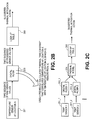
- the thermal time constant if the thermal time constant has been correctly determined, the time sequence of computed effective temperatures or processed sensor values (at the output of the digital filter 203) will have time response characteristics that are similar in profile to the real temperatures of interest (namely those of location B), though they may be different in terms of absolute value. It is these effective temperatures or processed sensor values, computed by the signal processing operation defined by the thermal time constant, that are then used to monitor the real thermal behavior of the target location in any subsequent thermal management operation. For example, in Fig.
- a sample taken from the time sequence of processed sensor values is applied to a previously calculated look-up table 205, to find a matching, suggested thermal mitigation action (if any).
- Tables 1 and 2 below are examples of such look-up tables.
- the look-up table may be implemented as a data structure stored in memory.
- more sophisticated signal processing techniques may be applied within the digital filter 203, to compute the effective temperatures or processed sensor values, including but not limited to multiple-pole filters or Finite Impulse Response (FIR) filters, in order to improve the correlation between the available sensors and the real temperature of the target location.
- FIR Finite Impulse Response
- Fig. 2C more sophisticated statistical analysis techniques may be applied to predict the real thermal behavior of the target location - see Fig. 2C .
- the digital filter output of multiple sensors 201_1, 201_2, ... are transformed through a mathematical "thermal model" implemented by a temperature calculator 204, into a final prediction of the temperature at the target location.
- Techniques to build this thermal model include, but are not limited to, Principal Component Analysis and Multiple Linear Regression. See also US patent application serial no. 12/250,498 filed Oct 13, 2008 that has been assigned to the same assignee as that of the present application, for additional details concerning the particular approach taken in Fig. 2C for estimating the temperature of the remote, target location.
- a light emitting diode (LED) backlight has the following characteristic: its light output decreases about in direct proportion to a decrease in its power consumption.
- the response of the human visual perception system to light intensity is approximately logarithmic, in the sense that a large increase in light intensity (e.g ., a doubling of backlight power) is needed to achieve a relatively small improvement in perceived brightness.
- the default backlight power is set to, for example, about 50% of its maximum specified power. Thereafter, when there is a threshold thermal event, the backlight power is reduced to an amount that yields about one half the perceived brightness by a human. This has been experimentally determined to be about 20% of the maximum specified power of a typical LED backlight used in handheld device applications such as cellular phones. Lowering the backlight power further has been found to not result in an appreciable decrease in the heat produced by the backlight, and in fact is likely to make the display screen very difficult to see. This process helps achieve a significant reduction in heat produced by the backlight, without significantly impacting the user's experience with the device.
- the transmit rate of the cellular network transceiver is the transmit rate of the cellular network transceiver.
- the device may have third generation, 3G, cellular network communications hardware and software that enable its user to surf the Web, check email, and download video at greater speeds. In that case, the device may reduce its 3G, High Speed Downlink Packet Access, HSDPA, transmit rate or limit its RF output power in response to a thermal event.
- 3G Third Generation
- HSDPA High Speed Downlink Packet Access
- FIG. 5 A thermal management process in accordance with an embodiment of the invention is now described in some detail, with reference to the flow diagram of Fig. 5 .
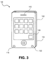
- the process can be used to control temperature in the example multifunction portable communications device 100 that is depicted in Fig. 3 and Fig. 4 .
- Fig. 3 is an external view of the device, while Fig. 4 shows a few components of interest by revealing several layers that make up the device.
- This device 100 may be an iPhoneTM device by Apple Inc.
- the device 100 has within its external case or housing 102 the following components that operate together to provide cellular phone, web surfing and digital media playback functions to its user: a CPU 404, a touch sensitive display screen 108 with a built-in backlight, a cellular baseband processor 408, cellular network RF transceiver PAs 409, 410, microphone 114, receiver (ear speaker) 112, speaker 122, and battery 404.
- the display screen 108 need not be touch sensitive; instead, user input may be had through a separate, built-in, physical keyboard or keypad (not shown).
- Additional temp sensors may be included, such as one that is associated with a Subscriber Identity Module, SIM card (not shown) or is on-chip with the baseband processor 408 in the device 100.
- the battery 404 is located at the rear of the device 100, in front of a back case or panel 104 which is part of the external case 102, while the display screen 108 is at its front.
- the battery 404 faces the back face of a printed wiring board (pwb) 419 on which the CPU 404, baseband processor 408, and PA 410 are installed.
- a separator panel 415 may be included for greater structural integrity and/or heat insulation, between the battery 404 and the board 419.
- the PAs 409, 410 in this example are soldered to the front face of the board 419.
- thermo management program stored in memory 417, may be executed by the CPU or by another processor within the device, to perform some of the operations recited in Fig. 5 .
- Fig. 5 beginning in the laboratory setting, statistical techniques and direct, instrumentation-type temperature measurements of a target location of interest in the device are taken, versus simultaneously taken readings given by one or more temp sensors that are built-into in the device but that may be "remote" from the target location (block 504).
- a range of temperatures of interest are covered, e.g. 40-70 degrees, by heating the device 100 from an external source and/or allowing the device 100 to heat up by virtue of its own operation.
- a suitable time interval is defined over which the measurements are taken (e.g ., several minutes).
- a number of specimens of the same device 100 can be connected to the instrumentation circuitry to take such measurements, and the resulting laboratory data is recorded for statistical analysis.
- a mathematical relationship may then be derived from the recorded lab data, which relates one variable that indicates the hot spot temperature, to another variable, namely the temperature sensed by one or more temp sensors (block 508).
- This relationship may have two aspects. First, there is the contribution by the thermal time constant introduced above in connection with Fig. 1 and Fig. 2A , to obtain the "processed" curve. This aspect is reflected in operation 509 in which digital filter coefficients are generated that shape the time response of a digital filter so that the filter's output matches the envelope of the temperature vs. time behavior of the target location, when its input is a sequence of temperature readings from one or more remote sensors. The computed filter coefficients are then stored or encoded in the manufactured specimens of the device 100. Second, a further relationship that makes an adjustment to the processed curve to obtain an estimate of the real temperature of the target location, is determined.
- the hot spot of the battery 404 may be the part of the battery that is closest to the PAs 409, 410.
- Instrumentation-based measurements of such a battery hot spot reveal that whenever it is near or in its maximum temperature range (as specified by, for example, the battery's manufacturer), this is generally due to the heat produced by the PAs 409, 410, which are located nearby.
- a better indicator of the battery hot spot temperature in the absence of a temp sensor that just happens to be located at the battery hot spot
- An even better indicator of the battery temperature is the processed version of the output of RF temp sensor 416, i.e. a sequence of temperature measurements made by the RF temp sensor 416 that has undergone digital signal processing designed to track the actual rise and fall in battery temperature.
- a digital filter may be defined in operation 509.
- a further mathematical relationship may be needed (e.g., to convert the "processed" curves of Figs. 1-2A into estimates of the real target location temperature.
- K1 and K2 are constants that are selected to best fit a curve (here, a straight line) to the experimental data representing the actual battery hot spot temperature.
- the temperature relationship (equation 1) between battery hot spot and processed RF temp sensor may be reflected in a predefined lookup table stored in the memory 417 of the device 100 (block 512).
- the table associates or maps a list of battery hot spot temperatures of interest, e.g . those that are in a band at or near the maximum temperature specified by the battery's manufacturer, to processed RF temp sensor thresholds (in accordance with the predefined relationship).
- the table lists a respective power consumption change command or function limit, to be issued in the device in response to the threshold being reached, to mitigate a thermal situation.
- a corresponding blank entry in the Special Action column refers to a "no change" command, i.e. no change to the power consumption of the components in the device is needed. See for instance Table 1 below. Note each threshold value in the table may actually represent a respective, band or range of temperature values that define the thermal event.
- the relevant column here is the "Processed RF PA Sensor Threshold” column, which reflects the thermal time constant of a target location, e.g. the battery hot spot, relative to a temperature sensor located at the RF power amplifiers.
- Table 1 may be used in-the-field, as follows - see blocks 516-524 of the flow diagram in Fig. 5 . Note that unless otherwise specified, the order in which the operations or steps of a process can occur is not limited to that which is shown in an associated flow diagram. Referring now to the flow diagram in Fig. 5 , consider a reading taken from the RF temp sensor in the field and that has been processed in accordance with a thermal time constant associated with a target location (block 516). This single reading may be sufficient to index into the look up table, to determine what power consumption action to take; alternatively, it may be combined with a reading from one or more other temp sensors.
- Table 1 above indicates that once the processed RF temp has risen to a certain level, a particular action should be taken with respect to a certain component of the device.
- the table shows how to respond to progressively rising RF temp sensor readings.
- the backlight is dimmed to 70% of its maximum power level.
- the backlight is further dimmed to 50%.
- the table indicates when most if not all applications executing in the device will be killed, as the temperature continues to rise.
- the table indicates that it is time to put the device into a low power sleep state.
- the temperature reading from a given temp sensor is used to index into the table, to thereby identify a power consumption action associated with a component of the device 100 (block 520).
- the identified power consumption action is applied to the component (block 524), to achieve the expected change in thermal behavior of the device 100.
- the look-up table which may be stored as part of thermal management software in the device 100, need not list all of the columns of Table 1.
- the table may only list the (previously computed) temp sensor values and their respective power consumption actions, as correlated to real target location temperatures.
- the process in that case works by indexing directly into the look-up table, using a processed temp sensor reading. This may be viewed as the temp sensor domain embodiment.
- the estimated target location temperature can be obtained by plugging the processed temp sensor value into equation 1.
- the look-up table stored in the device 100 need only list the target location temperatures (and their respective power consumption actions). The process would then work by first plugging the processed temp sensor reading into equation 1, and then directly indexing into the look-up table with the computed or estimated target location temperature.
- a thermal management process controls the device's external case temperature.
- the target location in the flow diagram of Fig. 5 becomes for example the center of the back case or panel 104 of the device 100.
- the in-the-field device portion of this process (namely blocks 516-524) may be executed in parallel with the battery hot spot process described above.
- the battery temp sensor output may be a reasonably reliable predictor for the external case temperature, particularly in the example device 100 depicted in Fig. 4 .
- thermal management processes (in connection with Table 1) gave as examples several power consumption change commands for thermal mitigation, including backlight dimming, killing applications, and forcing the entire device 100 into a low power sleep state.
- Table 2 below gives an example of another thermal mitigation action, namely that of limiting RF transmit power. That table shows a list of battery hot spot temperatures of interest, mapped to corresponding processed RF PA temp sensor readings (using the predefined relationship obtained from experimental data), and the corresponding RF output or transmit power limits that are to be placed on the RF PA 409, 410 (see Fig. 4 ).
- Table 2 may be used by another thermal management process that is running in the device, in parallel with those described above in connection with Table 1.
- Table 2 describes how to limit the transmit power as a function of battery hot spot temperature, the latter having been correlated to the RF PA temp sensor which is being monitored.
- Table 1 suggests dimming the backlight to 50% while Table 2 suggests limiting the RF transmit power to 22.5 dBm.
- One or both of these thermal mitigation actions are then taken ( Fig. 5 , operation 524).
- the power consumption mitigation action taken at a given temperature threshold includes limiting the RF transmit power to the specified level.
- the RF transmit power of the device 200 shall not be allowed to increase above 21 dBm when the processed battery temp sensor data (as correlated to the center of the back case) is indicating about 56.79 degrees.
- the RF transmit power might have to be limited to such a low level (based on Table 3), that the cellular base station tower with which the device 100 is communicating may decide to drop the ongoing phone call or, if possible, initiate a smooth hand over of the call from, for example, a 3G cellular network to one that uses lower (overall) RF power, e.g. a 2G network.
- Slowly reducing the available transmit power in the manner shown in Table 3 may be a better option than the device 100 itself deciding to drop the call altogether ( e.g., by killing a cellular phone application that is running). Reducing the available transmit power gradually as indicated in Table 3, while allowing an ongoing call to continue even as the device gets hotter, will give the cellular network a chance to hand over the call to another wireless cellular network communications protocol that calls for lower power consumption in the device 100.
- the cell tower may be continuously or repeatedly commanding each of the phones with which it is communicating to adjust their respective RF transmit power levels during phone calls (e.g., as a particular phone moves closer to or farther from the cell tower, or as the number of active phone calls being handled by the cell tower changes).
- the command from the cell tower and the command in Table 3 e.g. the cell tower may demand more power, while Table 3 requests a reduction (due to increasing, processed battery temp sensor readings). In that case, Table 3 may override the cell tower's request for greater power.
- the cell tower may signal the device 100 to reduce its transmit power level, even while Table 3 allows a higher limit. In those situations, the device may prefer to operate at the lower level.
- Hysteresis may be incorporated into the thermal management processes described above. For example, with hysteresis, as the device cools off and the temp sensor readings drop, a higher power consumption command or limit (indicated in one of the tables above and that is associated with the new lower temperature level), is not resumed immediately. Rather, the process delays resumption of the higher power consumption level, to for example ensure that the device is in fact cooling off at a sufficiently high rate. For instance, hysteresis may require that the processed temp sensor reading further drop by about 1 ⁇ 2 degree, relative to one of the threshold levels indicated in the table, before the higher power consumption associated with that threshold level is resumed or permitted.
- the device 100 may also have a fail-safe process or mode in which several components of the device (e.g., cellular network PA, backlight, music player functionality) are essentially shut down due to excessive temperature.
- the fail-safe mode may be entered when there is a thermal event that risks violating the predefined maximum battery temperature range, e.g. beyond 63 degrees.
- the device 100 may have a process that first alerts the user, by showing a graphic on the display screen 108, when a temperature limit that is near a hot limit (or other maximum specified operating temperature of the device) has been reached.
- a temperature limit that is near a hot limit or other maximum specified operating temperature of the device
- the battery hot spot may be at its manufacturer specified maximum, or the back case center may be at a UL specified maximum or other maximum user comfort temperature. This allows the user himself to then immediately end the call for example, or shut down a particularly power-hungry application that may be running.
- the process could automatically invoke a reset and/or reboot of the entire device and its operating system.
- the look up table is thus said to correlate temp sensor readings with the expected, actual temperature of a remote, target location.
- the look up table need not actually contain a list of either of those values.
- Table 1 above lists only processed RF PA temp sensor values, not raw sensor readings (and one or more associated power consumption actions, "Special Actions" column, that are suggested to mitigate, e.g., reduce, the actual temperature of the target location at selected temperature thresholds).
- the list of processed readings could be mapped to (and replaced with) their corresponding, computed target location values. See for example equation 1 which gives the computed temperature values of the battery hot spot, based on processed RF PA temp sensor readings.
- thermal management processes can run in parallel, to control the power consumption of various components of the device simultaneously, based on information obtained from the same temp sensors.
- these processes need not have any memory of for example how long (time wise) a particular processed temp sensor variable has been indicating above a given threshold. See Fig. 2B , showing the "open loop" nature of the process.
- they do not actually regulate the temperature of a given part of the device, to ensure that it stays in a narrow, target range. Rather, they respond to temperature changes (according to the tables) across a relatively broad range. For instance, Table 1 covers the ranges 57-64 degrees and 51-61 degrees, the range for Table 2 is 59-63 degrees, and the range for Table 3 is 53-60 degrees.
- a regulating closed loop thermal management process (that runs in the device) regulates the temperature of a target location within a relatively narrow temperature range, based on taking readings from one or more remotely located temp sensors in the device 100.
- a suitable, relatively narrow, battery hot spot temperature range may be 62-64 degrees.
- this battery temperature band should be not too high as to significantly reduce the life of the battery (or render the external case too hot), and not too low to render inefficient operation given the battery chemistry.
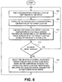
- a process that can maintain this narrow temperature is depicted in Fig. 6 .
- a sample, processed reading is taken, from a sequence of such readings taken from a remotely located temp sensor in the device 100 (block 604).
- the sequence of readings had been processed, so that they correlate better with the temperature behavior of a target location.
- the sample, processed reading is further correlated with the temperature of the target location (block 608).
- the latter may be performed in part by inserting the processed temp sensor value into a previously defined equation (e.g., one of the linear equations described above), that actually computes an accurate estimate of the corresponding target location temperature.
- the computed target location temperature is then compared to the suitable, battery hot spot range (block 612) to determine an error. If the error is not small enough (block 613), then one or more of several predefined, power consumption actions that would reduce the error are selected and applied (block 616). The expectation is that this application of power consumption actions will correct the target location's temperature, back into the suitable range.
- a temp sensor's behavior history, and/or a thermal time constant associated with the sensor has been stored in memory of the device, either by itself or correlated to that of a target location. This information can be consulted, e.g . as part of block 616, to further determine for example the strength of the power consumption action that will be taken. For instance, if the back case center has been steadily cooling for the past 30 seconds (as indicated by monitoring the battery temp sensor for example), even though the back case center is still above its suitable temperature range, the limit on RF transmit power of the device 100 should be reduced only slightly, as compared to the situation where the back case center has been fluctuating (rather than steadily cooling) above its suitable range.
- An embodiment of the invention may be a machine-readable medium having stored or encoded thereon instructions which program a processor to perform some of the operations described above. In other embodiments, some of these operations might be performed by specific hardware components that contain hardwired logic.
- the digital filter 203 in Fig. 2B may be implemented entirely as a programmable logic array circuit, or entirely as a programmed data processor. Those operations might alternatively be performed by any combination of programmed computer components and custom hardware components.
- a machine-readable medium may include any mechanism for storing or transmitting information in a form readable by a machine (e.g ., a computer), not limited to Compact Disc Read-Only Memory (CD-ROMs), Read-Only Memory (ROMs), Random Access Memory (RAM), and Erasable Programmable Read-Only Memory (EPROM).
- a machine e.g ., a computer
- CD-ROMs Compact Disc Read-Only Memory
- ROMs Read-Only Memory
- RAM Random Access Memory
- EPROM Erasable Programmable Read-Only Memory
- the invention is not limited to the specific embodiments described above.
- the temperature threshold numbers in the tables here are only one instance of how each table can be populated.
- the threshold value is approximate in that that there is a tolerance band around each value.
- the more general concepts described here are of course not limited to the specific numbers in any given table. Accordingly, other embodiments are within the scope of the claims.
Landscapes
- Engineering & Computer Science (AREA)
- Theoretical Computer Science (AREA)
- Physics & Mathematics (AREA)
- General Engineering & Computer Science (AREA)
- General Physics & Mathematics (AREA)
- Human Computer Interaction (AREA)
- Computer Hardware Design (AREA)
- Telephone Function (AREA)
- Power Sources (AREA)
- Radiation Pyrometers (AREA)
Claims (23)
- Verfahren zur thermischen Verwaltung einer elektronischen Vorrichtung, das Verfahren umfassend:Schätzen der Temperatur eines Zielortes, wie beispielsweise eines Batteriehotspots oder einer Gehäuserückseitenmitte der Vorrichtung unter Verwendung eines Temperatursensors, der an einem fernen Ort fern von dem Zielort ist, durchwobei die Nachschlagetabelle eine Temperatur an dem Temperatursensor mit einer Temperatur an dem Zielort korreliert und wobei die entsprechenden Leistungsverbrauchbefehle für eine Vielzahl von Keine-Änderung-Befehle und zumindest einen Änderung-Befehl beinhalten, der den Leistungsverbrauch der Komponente beschränkt oder reduziert, um eine thermische Situation abzuschwächen und um eine erwartete Änderung in dem thermischen Verhalten der Vorrichtung zu erreichen.(a) Filtern einer Sequenz von Temperaturmesswerten von dem Temperatursensor, der an einem fernen Ort in der Vorrichtung (516) ist, und(b) Verwenden eines aus den gefilterten Temperaturmesswerten, um auf eine Nachschlagetabelle zuzugreifen, welche Temperaturschwellen und entsprechende Leistungsverbrauchbefehle auflistet und dabei einen Leistungsverbrauchbefehl, der mit einer Komponente der Vorrichtung (520) assoziiert ist, identifiziert, wobei der Zielort ferner von der Komponente gelegen ist,
- Verfahren nach Anspruch 1 ferner umfassend:Wiederholen von (b), um so einen anderen einen aus den gefilterten Temperaturmesswerten zu verwenden, um auf die Nachschlagetabelle zuzugreifen, bis der zumindest eine Änderung-Befehl identifiziert ist; undAnwenden des identifizierten Änderung-Befehls, um den Leistungsverbrauch einer Komponente der Vorrichtung (524) zu beschränken oder zu reduzieren.
- Verfahren nach Anspruch 1, wobei die Liste der Temperaturschwellen in der Nachschlagetabelle sich auf Temperatur an dem Zielort der Vorrichtung bezieht, und
wobei das Verwenden des gefilterten Temperaturmesswerts, um auf die Nachschlagetabelle zuzugreifen, ein Umwandeln, unter Verwendung einer vordefinierten mathematischen Beziehung, des gefilterten Temperaturmesswertes in einen Wert, welcher sich auf die Temperatur an dem Zielort (519) bezieht, umfasst. - Verfahren nach Anspruch 1, wobei die Liste von Temperaturschwellen in der Nachschlagetabelle sich auf gefilterte Temperaturmesswerte bezieht, wobei die Verwendung der gefilterten Temperaturmesswerte umfasst:direktes Indizieren in die Nachschlagetabelle mit dem gefilterten Temperaturmesswert (520).
- Verfahren nach Anspruch 2, wobei Anwenden des identifizierten Änderung-Befehls auf die Komponente der Vorrichtung umfasst:Beschränken der HF-Übertragungsleistung eines Sendeempfängers für ein zelluläres Netzwerk in der Vorrichtung auf eine Stufe, die durch den identifizierten Änderung-Befehl angegeben ist.
- Verfahren nach Anspruch 2, wobei Anwenden des identifizierten Änderung-Befehls auf die Komponente der Vorrichtung umfasst:Reduzieren einer Lichtausgabe einer Anzeigebildschirmhintergrundbeleuchtung in der Vorrichtung auf eine Stufe, die durch den identifizierten Änderung-Befehl angegeben ist.
- Verfahren nach Anspruch 1, wobei Anwenden des identifizierten Änderung-Befehls auf die Komponente der Vorrichtung umfasst:Reduzieren einer Taktfrequenz oder einer Versorgungsspannung einer Datenverarbeitungseinheit in der Vorrichtung auf eine Stufe, die durch den identifizierten Änderung-Befehl angegeben ist.
- Verfahren nach Anspruch 1, wobei zumindest ein Änderung-Befehl dazu dient das Verhalten der Vorrichtung zu verwalten, so dass die Temperatur der Batterie innerhalb eines gegebenen vordefinierten Batteriebereichs verbleibt und so dass die Temperatur der Gehäuserückseite innerhalb eines gegebenen vordefinierten Bereichs des externen Gehäuses bleibt.
- Verfahren nach Anspruch 1, wobei der zumindest eine Änderung-Befehl dazu dient, einen gegebenen Temperaturbereich der Batterie oder der Gehäuserückseite beizubehalten durch Verwenden des Leistungsverbrauchbefehls zum Reduzieren der Menge an Hitze, die durch die Komponente an der Batterie oder dem externen Gehäuse verursacht wird.
- Verfahren nach Anspruch 1, wobei der Temperatursensor an einer hitzeerzeugenden Komponente gelegen ist, welche eine der folgenden umfasst:einen HF-Leistungsverstärker, die Batterie, jedoch nicht den Batteriehotspot, On-Chip mit einem zellulären Basisbandprozessor, nahe einer Subscriber-Identity-Module-Card-Schaltung.
- Verfahren nach Anspruch 1, wobei die Nachschlagetabelle eine Temperatur basierend auf laborinstrumentenartigen Temperaturmessungen von Zielorten von Interesse mit simultanaufgenommenen Temperaturmesswerten durch Temperatursensoren, welche in ein Exemplar der Vorrichtung an Orten fern von den Zielorten eingebaut sind, für einen Bereich von Temperaturen, über eine geeignete Zeitdauer, für eine Anzahl von Exemplaren der Vorrichtung, korreliert.
- Verfahren nach Anspruch 11, wobei die Temperaturmessungen und Temperaturmesswerte eine mathematische Beziehung bereitstellen, welche eine thermische Zeitkonstante und eine Anpassung einer verarbeiteten Temperatursensorkurve der Temperaturmesswerte beinhalten.
- Verfahren nach Anspruch 12, wobei die mathematische Beziehung eine Schätzung der realen Temperatur der Zielorte bestimmt und eine lineare Beziehung zwischen den Temperaturmessungen und den Temperaturmesswerten basierend auf der Gleichung: Zielorttemperatur = K1 + K2 x Temperaturmesswert, bereitstellt.
- Verfahren nach Anspruch 1, wobei Schätzen der Temperatur eines Zielortes ein Schätzen der Temperatur von zwei Zielorten umfasst, welche der Batteriehotspot und die Gehäuserückseitenmitte der Vorrichtung sind, unter Verwendung von zwei Temperatursensoren, die an fernen Orten fern von den Zielorten sind; wobei Filtern ein Filtern der Sequenz von den zwei Temperatursensoren umfasst; und wobei Verwenden ein Verwenden von einem aus den gefilterten Temperaturmesswerten von jedem der Temperatursensoren umfasst, um auf die Nachschlagetabelle zuzugreifen, und dabei einen einzelnen Leistungsverbrauchbefehl basierend auf beiden aus den gefilterten Temperaturmesswerten zu identifizieren.
- Elektronische Vorrichtung umfassend:einen Temperatursensor (201); undeinen thermischen Verwalter, der ein digitales Filter (203) aufweist, dessen Eingabe es ist, rohe Temperaturwerte von dem Sensor (201) zu empfangen und dessen Ausgabe es ist, verarbeitete Temperaturwerte entsprechend einer Filterfunktion bereitzustellen, welche Temperatur an dem Sensor mit Temperatur an einem fernen Zielort, wie beispielsweise eines Batteriehotspots oder einer Gehäuserückseitenmitte der Vorrichtung, korreliert, wobei der Temperatursensor (201) an einem fernen Ort fern des Zielortes ist,der thermische Verwalter eine Nachschlagetabelle (205) aufweist, welche ferner Temperatur an dem Sensor (201) mit Temperatur an dem Zielort korreliert, wobei die Nachschlagetabelle eine Liste von Temperaturwerten, welche einen Temperaturbereich an dem Sensor oder an dem Zielort repräsentiert und eine Vielzahl von Leistungsverbrauch-Änderung-Befehlen, die jeweils mit der Liste von Temperaturwerten assoziiert sind, aufweist,den thermischen Verwalter, um auf die Nachschlagetabelle (205) eine Vielzahl von Malen zuzugreifen, jedes Mal einen unterschiedlichen einen aus den verarbeiteten Temperaturwerten verwendet, um eine Vielzahl von Leistungsverbrauch-Änderung-Befehlen zu identifizieren und die identifizierte Vielzahl von Leistungsverbrauch-Änderung-Befehlen zu bewerten, um zu bestimmen, welche Änderung, falls eine vorhanden ist, an den Leistungsverbrauch einer Komponente in der Vorrichtung befohlen werden soll, um eine thermische Situation abzuschwächen und um eine erwartete Änderung in einem thermischen Verhalten der Vorrichtung zu erreichen, wobei der Zielort fern von der Komponente gelegen ist.
- Elektronische Vorrichtung nach Anspruch 15 ferner umfassend:einen drahtlosen Kommunikations-Sendeempfänger-HF-Leistungsverstärker (409, 410), wobei ein aus den identifizierten Leistungsverbrauch-Änderung-Befehlen eine HF-Ausgabeleistungsbeschränkung des Leistungsverstärkers ist.
- Elektronische Vorrichtung nach Anspruch 15 ferner umfassend:einen Anzeigebildschirm (108), der eine Hintergrundbeleuchtung aufweist, wobei ein aus den identifizierten Leistungsverbrauch-Änderung-Befehlen eine Helligkeitsbeschränkung der Hintergrundbeleuchtung ist.
- Elektronische Vorrichtung nach Anspruch 15 ferner umfassend:eine zentrale Verarbeitungseinheit, CPU (404), wobei ein aus den identifizierten Leistungsverbrauch-Änderung-Befehlen eine Prozessortaktbeschränkung oder eine Versorgungsspannungsbeschränkung der CPU ist.
- Elektronische Vorrichtung nach Anspruch 15, wobei der thermische Verwalter Speicher (417) umfasst, in welchem eine Historie von Temperaturmesswerten des Sensors gespeichert ist, welche mit der Temperatur an dem anderen Ort korreliert worden sind,
der thermische Verwalter die gespeicherte Historie konsultiert, und auf dieser Basis die Stärke der Änderung, welche an den Leistungsverbrauch der Komponente in der Vorrichtung befohlen wird, anpasst. - Elektronische Vorrichtung nach Anspruch 15, wobei der thermische Verwalter dazu dient eine Hysterese zu implementieren, so dass, wenn die Vorrichtung abkühlt, ein identifizierter Leistungsverbrauchbefehl aus der Nachschlagetabelle, der den Leistungsverbrauch einer Komponente in der Vorrichtung erhöht, nicht sofort wieder aufgenommen wird, sondern verzögert wird bis die Vorrichtung weiter abgekühlt ist.
- Elektronische Vorrichtung nach Anspruch 15, wobei die Vielzahl von Temperaturwerten, die in der Nachschlagetabelle aufgelistet sind, in dem Bereich von 50-65°C liegen.
- Elektronische Vorrichtung nach Anspruch 15, wobei die Änderung, falls eine vorhanden ist, die dem Leistungsverbrauch einer Komponente in der Vorrichtung befohlen werden soll, dazu dient, das Verhalten der Vorrichtung zu verwalten, so dass die Temperatur der Batterie innerhalb eines gegebenen vordefinierten Batteriebereichs bleibt und so dass die Temperatur des externen Gehäuses innerhalb eines gegebenen vordefinierten Bereichs des externen Gehäuses bleibt.
- Elektronische Vorrichtung nach Anspruch 15, wobei die Änderung, falls eine vorhanden ist, die dem Leistungsverbrauch einer Komponente in der Vorrichtung befohlen werden soll, dazu dient, einen gegebenen Temperaturbereich an der Batterie oder dem externen Gehäuse beizubehalten durch Verwenden des Leistungsverbrauchbefehls, um die Menge an Hitze zu reduzieren, welche durch die Komponente an der Batterie oder dem externen Gehäuse verursacht wird.
Applications Claiming Priority (3)
| Application Number | Priority Date | Filing Date | Title |
|---|---|---|---|
| US5776708P | 2008-05-30 | 2008-05-30 | |
| US12/370,946 US8315746B2 (en) | 2008-05-30 | 2009-02-13 | Thermal management techniques in an electronic device |
| PCT/US2009/041036 WO2009148710A1 (en) | 2008-05-30 | 2009-04-17 | Thermal management techniques in an electronic device |
Publications (2)
| Publication Number | Publication Date |
|---|---|
| EP2294497A1 EP2294497A1 (de) | 2011-03-16 |
| EP2294497B1 true EP2294497B1 (de) | 2016-05-25 |
Family
ID=41380777
Family Applications (1)
| Application Number | Title | Priority Date | Filing Date |
|---|---|---|---|
| EP09758873.5A Active EP2294497B1 (de) | 2008-05-30 | 2009-04-17 | Wärmemanagementtechniken in einer elektronischen anordnung |
Country Status (4)
| Country | Link |
|---|---|
| US (2) | US8315746B2 (de) |
| EP (1) | EP2294497B1 (de) |
| CN (1) | CN102099761B (de) |
| WO (1) | WO2009148710A1 (de) |
Families Citing this family (151)
| Publication number | Priority date | Publication date | Assignee | Title |
|---|---|---|---|---|
| DE102006040408A1 (de) * | 2006-08-29 | 2008-03-13 | Abb Patent Gmbh | Verfahren zum Betrieb einer Fühleranordnung |
| US8315746B2 (en) | 2008-05-30 | 2012-11-20 | Apple Inc. | Thermal management techniques in an electronic device |
| CN102246384B (zh) | 2008-10-02 | 2015-09-23 | 埃科亚特姆公司 | 针对设备的二手市场和自动售货系统 |
| US7881965B2 (en) | 2008-10-02 | 2011-02-01 | ecoATM, Inc. | Secondary market and vending system for devices |
| US20130124426A1 (en) * | 2008-10-02 | 2013-05-16 | ecoATM, Inc. | Method And Apparatus For Recycling Electronic Devices |
| US11010841B2 (en) | 2008-10-02 | 2021-05-18 | Ecoatm, Llc | Kiosk for recycling electronic devices |
| US9881284B2 (en) | 2008-10-02 | 2018-01-30 | ecoATM, Inc. | Mini-kiosk for recycling electronic devices |
| US10853873B2 (en) | 2008-10-02 | 2020-12-01 | Ecoatm, Llc | Kiosks for evaluating and purchasing used electronic devices and related technology |
| US8306772B2 (en) | 2008-10-13 | 2012-11-06 | Apple Inc. | Method for estimating temperature at a critical point |
| US9495272B2 (en) * | 2009-06-11 | 2016-11-15 | Oracle America, Inc. | Method and system for generating a power consumption model of at least one server |
| US8487759B2 (en) | 2009-09-30 | 2013-07-16 | Apple Inc. | Self adapting haptic device |
| US8504855B2 (en) | 2010-01-11 | 2013-08-06 | Qualcomm Incorporated | Domain specific language, compiler and JIT for dynamic power management |
| US9235251B2 (en) * | 2010-01-11 | 2016-01-12 | Qualcomm Incorporated | Dynamic low power mode implementation for computing devices |
| US8965716B2 (en) * | 2010-04-05 | 2015-02-24 | Lear Corporation | Method and apparatus for testing at least one temperature sensor in a vehicle |
| US8843736B2 (en) | 2010-05-04 | 2014-09-23 | Sony Corporation | Authentication and authorization for internet video client |
| US8458741B2 (en) * | 2010-05-27 | 2013-06-04 | Sony Corporation | Provision of TV ID to non-TV device to enable access to TV services |
| US8407755B2 (en) | 2010-07-27 | 2013-03-26 | Sony Corporation | Control of IPTV using second device |
| US10013058B2 (en) | 2010-09-21 | 2018-07-03 | Apple Inc. | Touch-based user interface with haptic feedback |
| US10120446B2 (en) | 2010-11-19 | 2018-11-06 | Apple Inc. | Haptic input device |
| US8996330B2 (en) | 2011-01-06 | 2015-03-31 | Qualcomm Incorporated | Method and system for managing thermal policies of a portable computing device |
| US8712598B2 (en) * | 2011-01-14 | 2014-04-29 | Microsoft Corporation | Adaptive flow for thermal cooling of devices |
| CA3087551C (en) | 2011-04-06 | 2023-11-07 | Ecoatm, Llc | Method and kiosk for recycling electronic devices |
| US8924752B1 (en) | 2011-04-20 | 2014-12-30 | Apple Inc. | Power management for a graphics processing unit or other circuit |
| US9207730B2 (en) | 2011-06-02 | 2015-12-08 | Apple Inc. | Multi-level thermal management in an electronic device |
| KR101840852B1 (ko) * | 2011-10-10 | 2018-03-22 | 삼성전자주식회사 | 모바일 장치의 표면 온도 관리 방법 및 멀티칩 패키지의 메모리 열관리 방법 |
| US8595520B2 (en) * | 2011-10-12 | 2013-11-26 | Qualcomm Incorporated | System and method for determining thermal management policy from leakage current measurement |
| US8856566B1 (en) | 2011-12-15 | 2014-10-07 | Apple Inc. | Power management scheme that accumulates additional off time for device when no work is available and permits additional power consumption by device when awakened |
| US9086862B2 (en) * | 2012-02-03 | 2015-07-21 | Getac Technology Corporation | Apparatus and method of protecting electronic apparatus using a temperature-power table for an electronic component under different system and environmental temperatures |
| CN104205110B (zh) | 2012-03-28 | 2018-10-26 | 英特尔公司 | 保护固件中的热管理参数免受计算机攻击 |
| CN102809591B (zh) * | 2012-04-11 | 2014-07-23 | 郑攀 | 用于胰岛素泵系统的温度自补偿血糖检测模块及补偿方法 |
| US9390461B1 (en) | 2012-05-08 | 2016-07-12 | Apple Inc. | Graphics hardware mode controls |
| US9035956B1 (en) | 2012-05-08 | 2015-05-19 | Apple Inc. | Graphics power control with efficient power usage during stop |
| US9250665B2 (en) | 2012-06-07 | 2016-02-02 | Apple Inc. | GPU with dynamic performance adjustment |
| WO2014006450A1 (en) * | 2012-07-03 | 2014-01-09 | Freescale Semiconductor, Inc. | Method and apparatus for managing a thermal budget of at least a part of a processing system |
| US9178509B2 (en) | 2012-09-28 | 2015-11-03 | Apple Inc. | Ultra low travel keyboard |
| KR20140047459A (ko) * | 2012-10-12 | 2014-04-22 | 삼성전자주식회사 | 전자 장치, 그 제어 방법 및 컴퓨터 판독가능 기록매체 |
| CN109937387B (zh) * | 2012-11-08 | 2022-08-23 | Ddm系统有限责任公司 | 金属部件的增材制造及维修 |
| US9431848B2 (en) | 2012-12-06 | 2016-08-30 | Samsung Electronics Co., Ltd | Method and apparatus for protecting wireless power receiver from excessive charging temperature |
| DE112012007229T5 (de) * | 2012-12-17 | 2015-09-24 | Hewlett-Packard Development Company, L.P. | Temperatur basierend auf Berührung einer tragbaren Rechenvorrichtung |
| US20140188302A1 (en) * | 2012-12-28 | 2014-07-03 | Vasudevan Srinivasan | Priority based intelligent platform passive thermal management |
| US9152473B2 (en) * | 2012-12-29 | 2015-10-06 | Intel Corporation | Table driven multiple passive trip platform passive thermal management |
| US20140244191A1 (en) * | 2013-02-28 | 2014-08-28 | Research In Motion Limited | Current usage estimation for electronic devices |
| US9286568B2 (en) | 2013-05-03 | 2016-03-15 | Asurion, Llc | Battery drain analysis and prediction for wireless devices |
| EP2802128B1 (de) * | 2013-05-06 | 2018-07-11 | Sensirion AG | Selbstkalibrierender Temperatursensor in einem mobilen Endgerät |
| EP2801804B1 (de) * | 2013-05-06 | 2018-07-11 | Sensirion AG | Selbstkalibrierender Temperatursensor in einem mobilen Endgerät |
| CN104182015B (zh) * | 2013-05-23 | 2018-04-27 | 联想(北京)有限公司 | 一种信息处理的方法及一种电子设备 |
| US9341520B2 (en) * | 2013-06-16 | 2016-05-17 | Qualcomm Incorporated | System and method for estimating ambient temperature of a portable computing device using a voice coil |
| WO2015020663A1 (en) | 2013-08-08 | 2015-02-12 | Honessa Development Laboratories Llc | Sculpted waveforms with no or reduced unforced response |
| US9720467B2 (en) | 2013-08-09 | 2017-08-01 | Qualcomm Incorporated | Thermal mitigation adaptation for a mobile electronic device |
| US9551599B2 (en) * | 2013-09-23 | 2017-01-24 | Rosemount Inc. | Normalized process dynamics |
| US9779592B1 (en) | 2013-09-26 | 2017-10-03 | Apple Inc. | Geared haptic feedback element |
| WO2015047343A1 (en) | 2013-09-27 | 2015-04-02 | Honessa Development Laboratories Llc | Polarized magnetic actuators for haptic response |
| US9886093B2 (en) | 2013-09-27 | 2018-02-06 | Apple Inc. | Band with haptic actuators |
| US10126817B2 (en) | 2013-09-29 | 2018-11-13 | Apple Inc. | Devices and methods for creating haptic effects |
| CN105683865B (zh) | 2013-09-30 | 2018-11-09 | 苹果公司 | 用于触觉响应的磁性致动器 |
| US20150108903A1 (en) * | 2013-10-18 | 2015-04-23 | Zippy Technology Corp. | Light sensing keyboard and a light emission control method thereof |
| US9317118B2 (en) * | 2013-10-22 | 2016-04-19 | Apple Inc. | Touch surface for simulating materials |
| US20150148981A1 (en) * | 2013-11-24 | 2015-05-28 | Qualcomm Incorporated | System and method for multi-correlative learning thermal management of a system on a chip in a portable computing device |
| US10276001B2 (en) | 2013-12-10 | 2019-04-30 | Apple Inc. | Band attachment mechanism with haptic response |
| US9959936B1 (en) * | 2014-03-12 | 2018-05-01 | Marvell International Ltd. | Temperature-based memory access |
| US10082847B2 (en) * | 2014-04-01 | 2018-09-25 | Qualcomm Incorporated | Method and system for optimizing performance of a PCD while mitigating thermal generation |
| US10545604B2 (en) | 2014-04-21 | 2020-01-28 | Apple Inc. | Apportionment of forces for multi-touch input devices of electronic devices |
| US9565081B2 (en) | 2014-05-19 | 2017-02-07 | Ebay Inc. | Phone thermal context |
| DE102015209639A1 (de) | 2014-06-03 | 2015-12-03 | Apple Inc. | Linearer Aktuator |
| KR20160026329A (ko) * | 2014-08-29 | 2016-03-09 | 삼성전자주식회사 | 내부 온도의 변화에 기초하여 성능을 제어하는 전자 장치 및 방법 |
| US9585100B2 (en) * | 2014-09-02 | 2017-02-28 | Apple Inc. | Cold temperature power throttling at a mobile computing device |
| US10555436B1 (en) * | 2014-09-02 | 2020-02-04 | Apple Inc. | Electronic device with thermal management system |
| KR102019505B1 (ko) | 2014-09-02 | 2019-09-06 | 애플 인크. | 햅틱 통지 |
| US10401411B2 (en) | 2014-09-29 | 2019-09-03 | Ecoatm, Llc | Maintaining sets of cable components used for wired analysis, charging, or other interaction with portable electronic devices |
| CA3074916A1 (en) | 2014-10-02 | 2016-04-07 | Ecoatm, Llc | Application for device evaluation and other processes associated with device recycling |
| CA2964214C (en) | 2014-10-02 | 2020-08-04 | ecoATM, Inc. | Wireless-enabled kiosk for recycling consumer devices |
| US10445708B2 (en) | 2014-10-03 | 2019-10-15 | Ecoatm, Llc | System for electrically testing mobile devices at a consumer-operated kiosk, and associated devices and methods |
| JP6827414B2 (ja) * | 2014-10-15 | 2021-02-10 | シグニファイ ホールディング ビー ヴィSignify Holding B.V. | 電力/データ通信を制御するための制御システム |
| US11080672B2 (en) | 2014-12-12 | 2021-08-03 | Ecoatm, Llc | Systems and methods for recycling consumer electronic devices |
| WO2016069742A1 (en) | 2014-10-31 | 2016-05-06 | ecoATM, Inc. | Methods and systems for facilitating processes associated with insurance services and/or other services for electronic devices |
| US20170169401A1 (en) | 2015-12-11 | 2017-06-15 | ecoATM, Inc. | Systems and methods for recycling consumer electronic devices |
| CA2966348C (en) | 2014-10-31 | 2019-11-12 | ecoATM, Inc. | Systems and methods for recycling consumer electronic devices |
| CA2967021C (en) | 2014-11-06 | 2024-03-12 | ecoATM, Inc. | Methods and systems for evaluating and recycling electronic devices |
| KR102256676B1 (ko) * | 2015-02-06 | 2021-05-26 | 삼성전자주식회사 | 전파 기반 센서 모듈을 이용하는 센싱 장치 및 이동 단말을 포함하는 다목적 디바이스 |
| US10353467B2 (en) | 2015-03-06 | 2019-07-16 | Apple Inc. | Calibration of haptic devices |
| US20160266629A1 (en) * | 2015-03-09 | 2016-09-15 | Advanced Micro Devices, Inc. | Changing power limits based on device state |
| US9958921B2 (en) * | 2015-03-09 | 2018-05-01 | Advanced Micro Devices, Inc. | Power management to change power limits based on device skin temperature |
| US9965020B2 (en) * | 2015-03-13 | 2018-05-08 | Dell Products L.P. | Systems and methods for power supply derating |
| CN104750137B (zh) * | 2015-03-17 | 2016-11-30 | 航天东方红卫星有限公司 | 一种基于查找表的卫星控温数据处理方法 |
| US9785209B2 (en) * | 2015-03-31 | 2017-10-10 | Qualcomm Incorporated | Thermal management in a computing device based on workload detection |
| US20160299179A1 (en) * | 2015-04-13 | 2016-10-13 | Mediatek Inc. | Scheme capable of estimating available power range according to extra power range and employing available power range as reference of performing power throttling upon a system |
| CN104793048B (zh) * | 2015-04-14 | 2018-01-16 | 清华大学 | 匹配器损耗功率的计算方法及装置 |
| AU2016100399B4 (en) | 2015-04-17 | 2017-02-02 | Apple Inc. | Contracting and elongating materials for providing input and output for an electronic device |
| GB2538332B (en) * | 2015-05-15 | 2017-09-06 | Tata Motors European Technical Ct Plc | Thermal Mapping Method And Apparatus |
| US11303126B1 (en) | 2015-05-22 | 2022-04-12 | Michael Lee Staver | Thermal management of power delivery |
| CN104955314B (zh) * | 2015-05-28 | 2017-10-20 | 广东欧珀移动通信有限公司 | 一种控制电子设备外壳温度的方法及电子设备 |
| WO2017044618A1 (en) | 2015-09-08 | 2017-03-16 | Apple Inc. | Linear actuators for use in electronic devices |
| CN105259996B (zh) * | 2015-09-23 | 2019-03-22 | 努比亚技术有限公司 | 移动终端温度调节装置和方法 |
| US9820409B1 (en) * | 2015-09-28 | 2017-11-14 | Amazon Technologies, Inc. | Rack cooling system |
| CN105511592A (zh) * | 2016-02-16 | 2016-04-20 | 上海斐讯数据通信技术有限公司 | 一种基于智能终端的温度值检测方法及智能终端 |
| US10039080B2 (en) | 2016-03-04 | 2018-07-31 | Apple Inc. | Situationally-aware alerts |
| ES2699703T3 (es) * | 2016-03-17 | 2019-02-12 | HD PLUS GmbH | Procedimiento y sistema para generar una lista de acceso a canales de medios |
| US10268272B2 (en) | 2016-03-31 | 2019-04-23 | Apple Inc. | Dampening mechanical modes of a haptic actuator using a delay |
| US11399720B2 (en) * | 2016-04-05 | 2022-08-02 | Qulacomm Incorporated | Circuits and methods providing temperature mitigation for computing devices |
| US10127647B2 (en) | 2016-04-15 | 2018-11-13 | Ecoatm, Llc | Methods and systems for detecting cracks in electronic devices |
| US9885672B2 (en) | 2016-06-08 | 2018-02-06 | ecoATM, Inc. | Methods and systems for detecting screen covers on electronic devices |
| US10269110B2 (en) | 2016-06-28 | 2019-04-23 | Ecoatm, Llc | Methods and systems for detecting cracks in illuminated electronic device screens |
| US10840726B2 (en) * | 2016-07-07 | 2020-11-17 | Apple Inc. | Electronic device with wireless charging and battery heating |
| US10007310B2 (en) * | 2016-07-08 | 2018-06-26 | Qualcomm Incorporated | Circuits and methods providing calibration for temperature mitigation in a computing device |
| US9924463B2 (en) * | 2016-08-29 | 2018-03-20 | Mediatek Singapore Pte. Ltd. | Method, system and apparatus for controlling power consumption of a mobile terminal |
| TWI599873B (zh) * | 2016-11-18 | 2017-09-21 | 廣達電腦股份有限公司 | 電子裝置以及電子裝置之溫度值處理方法 |
| US10969839B2 (en) | 2016-11-22 | 2021-04-06 | Intel Corporation | Restricting current draw in wearable devices |
| KR20180074377A (ko) * | 2016-12-23 | 2018-07-03 | 삼성전자주식회사 | 전자 장치 및 전자 장치의 배터리의 온도에 기반한 발열 제어 방법 |
| CN106655397B (zh) * | 2017-01-13 | 2019-06-14 | Oppo广东移动通信有限公司 | 充电控制方法、装置及电子设备 |
| US10218422B2 (en) * | 2017-03-24 | 2019-02-26 | Qualcomm Incorporated | Methods for beam switching in millimeter wave systems to manage thermal constraints |
| US10943516B2 (en) | 2017-05-15 | 2021-03-09 | Apple Inc. | Systems and methods of utilizing output of display component for display temperature compensation |
| US10622538B2 (en) | 2017-07-18 | 2020-04-14 | Apple Inc. | Techniques for providing a haptic output and sensing a haptic input using a piezoelectric body |
| DE102017217959A1 (de) * | 2017-10-09 | 2019-04-11 | Bayerische Motoren Werke Aktiengesellschaft | Verfahren und Vorrichtung zur Bestimmung einer Zelltemperatur |
| TWI646315B (zh) * | 2017-11-15 | 2019-01-01 | 財團法人工業技術研究院 | 溫度估算裝置及溫度估算方法 |
| US12176970B2 (en) * | 2018-06-12 | 2024-12-24 | Qualcomm Incorporated | Antenna element feed path component management for 5G-NR millimeter wave |
| US10691211B2 (en) | 2018-09-28 | 2020-06-23 | Apple Inc. | Button providing force sensing and/or haptic output |
| US10599223B1 (en) | 2018-09-28 | 2020-03-24 | Apple Inc. | Button providing force sensing and/or haptic output |
| US12322259B2 (en) | 2018-12-19 | 2025-06-03 | Ecoatm, Llc | Systems and methods for vending and/or purchasing mobile phones and other electronic devices |
| US11989710B2 (en) | 2018-12-19 | 2024-05-21 | Ecoatm, Llc | Systems and methods for vending and/or purchasing mobile phones and other electronic devices |
| CN109738779B (zh) * | 2019-01-30 | 2021-05-18 | 上海联影医疗科技股份有限公司 | 半导体结温计算方法、装置、计算机设备和存储介质 |
| KR20210126068A (ko) | 2019-02-12 | 2021-10-19 | 에코에이티엠, 엘엘씨 | 중고 전자 디바이스를 평가하고 구매하기 위한 키오스크 |
| EP3924917B1 (de) | 2019-02-12 | 2025-06-11 | ecoATM, LLC | Verbinderträger für ein elektronischen vorrichtungskiosk |
| JP2021530793A (ja) | 2019-02-18 | 2021-11-11 | エコエーティーエム, エルエルシー | 電子デバイスの物理的状態評価に基づくニューラルネットワーク、および関連付けられるシステムおよび方法 |
| CN112306199A (zh) * | 2019-07-30 | 2021-02-02 | Oppo广东移动通信有限公司 | 温度调整方法、装置、移动终端及存储介质 |
| US11380470B2 (en) | 2019-09-24 | 2022-07-05 | Apple Inc. | Methods to control force in reluctance actuators based on flux related parameters |
| CN110727559A (zh) * | 2019-10-09 | 2020-01-24 | Oppo广东移动通信有限公司 | 电子设备、电子设备控制方法及存储介质 |
| CN112698712B (zh) * | 2019-10-22 | 2022-12-06 | 华为技术有限公司 | 能耗管理的方法和设备 |
| CN110955580B (zh) * | 2019-12-09 | 2023-10-03 | Oppo广东移动通信有限公司 | 壳体温度的获取方法、装置、存储介质和电子设备 |
| EP4078494B1 (de) | 2019-12-18 | 2025-03-26 | ecoATM, LLC | Systeme und verfahren zum verkauf und/oder kauf von mobiltelefonen und anderen elektronischen vorrichtungen |
| CN113138036B (zh) * | 2020-01-19 | 2023-07-18 | 北京小米移动软件有限公司 | 温度检测方法及装置、电子设备 |
| WO2021183446A1 (en) | 2020-03-09 | 2021-09-16 | Psemi Corporation | Compact humidity sensor |
| CN113448489B (zh) * | 2020-03-25 | 2024-06-18 | 慧荣科技股份有限公司 | 控制闪存卡存取的计算机可读取存储介质、方法及装置 |
| CN111475384B (zh) * | 2020-05-07 | 2022-12-20 | Oppo广东移动通信有限公司 | 壳体温度的计算方法、装置、存储介质及电子设备 |
| US12475756B2 (en) | 2020-08-17 | 2025-11-18 | Ecoatm, Llc | Connector carrier for electronic device kiosk |
| US11922467B2 (en) | 2020-08-17 | 2024-03-05 | ecoATM, Inc. | Evaluating an electronic device using optical character recognition |
| US12271929B2 (en) | 2020-08-17 | 2025-04-08 | Ecoatm Llc | Evaluating an electronic device using a wireless charger |
| WO2022040667A1 (en) | 2020-08-17 | 2022-02-24 | Ecoatm, Llc | Evaluating an electronic device using a wireless charger |
| US12321965B2 (en) | 2020-08-25 | 2025-06-03 | Ecoatm, Llc | Evaluating and recycling electronic devices |
| CN112286259A (zh) * | 2020-11-12 | 2021-01-29 | 广州朗国电子科技有限公司 | 电子白板温度调节控制方法、装置、存储介质及热敏电路 |
| KR102889492B1 (ko) * | 2021-01-12 | 2025-11-21 | 삼성전자주식회사 | 전자 장치 및 그 제어 방법 |
| US11977044B2 (en) * | 2021-02-16 | 2024-05-07 | Murata Manufacturing Co., Ltd. | High linear range humidity sensor |
| US11977683B2 (en) | 2021-03-12 | 2024-05-07 | Apple Inc. | Modular systems configured to provide localized haptic feedback using inertial actuators |
| JP7512229B2 (ja) * | 2021-04-22 | 2024-07-08 | 株式会社東芝 | 情報処理装置、情報処理方法及びプログラム |
| CA3226383A1 (en) | 2021-07-09 | 2023-01-12 | Ecoatm, Llc | Identifying electronic devices using temporally changing information |
| US11809631B2 (en) | 2021-09-21 | 2023-11-07 | Apple Inc. | Reluctance haptic engine for an electronic device |
| EP4390925A4 (de) * | 2021-11-04 | 2025-01-01 | Samsung Electronics Co., Ltd. | Elektronische vorrichtung zur steuerung des betriebs eines flüchtigen speichers und betriebsverfahren dafür |
| NL2029996B1 (en) * | 2021-12-02 | 2023-06-20 | Microsoft Technology Licensing Llc | Cooling a computing device |
| US20240319712A1 (en) * | 2023-03-22 | 2024-09-26 | Advanced Micro Devices, Inc | Dynamic Range-Aware Conversion of Sensor Readings |
| US20250222746A1 (en) * | 2024-01-04 | 2025-07-10 | Gm Cruise Holdings Llc | Adaptive self-heating management of processors in autonomous vehicles |
| US20250276430A1 (en) * | 2024-03-01 | 2025-09-04 | Milwaukee Electric Tool Corporation | Power tool with impulse assembly |
| US12435732B1 (en) | 2024-09-19 | 2025-10-07 | Microsoft Technology Licensing, Llc | Centrifugal blower housing |
Family Cites Families (148)
| Publication number | Priority date | Publication date | Assignee | Title |
|---|---|---|---|---|
| US3730985A (en) * | 1970-09-18 | 1973-05-01 | Orloff F | Viewing and measuring system for remote thermal energy sources |
| US4060709A (en) * | 1976-04-28 | 1977-11-29 | Hanson Charles G | Power supply control |
| GB1544596A (en) * | 1976-10-06 | 1979-04-19 | Hitachi Heating Appl | High frequency energy apparatus |
| US4465077A (en) * | 1981-11-12 | 1984-08-14 | Howard Schneider | Apparatus and method of determining fertility status |
| US4445636A (en) * | 1982-08-25 | 1984-05-01 | American Stabilis, Inc. | Temperature comparison apparatus and methods |
| US4845647A (en) * | 1985-01-24 | 1989-07-04 | Accufiber, Inc. | Method and apparatus for determining temperature in a blackbody radiation sensing system |
| JPS62162565A (ja) * | 1986-01-14 | 1987-07-18 | Fujitsu Ltd | サ−マルヘツドの温度検出方式 |
| GB2233457A (en) | 1989-06-21 | 1991-01-09 | Schlumberger Technologies Ltd | Temperature reference junction for a multichannel temperature sensing system. |
| US5167024A (en) | 1989-09-08 | 1992-11-24 | Apple Computer, Inc. | Power management for a laptop computer with slow and sleep modes |
| US7194646B1 (en) * | 1989-10-30 | 2007-03-20 | Texas Instruments Incorporated | Real-time thermal management for computers |
| US5396635A (en) | 1990-06-01 | 1995-03-07 | Vadem Corporation | Power conservation apparatus having multiple power reduction levels dependent upon the activity of the computer system |
| US5230074A (en) * | 1991-01-25 | 1993-07-20 | International Business Machines Corporation | Battery operated computer power management system |
| WO1993007557A1 (fr) | 1991-10-02 | 1993-04-15 | Kabushiki Kaisha Toshiba | Appareil electronique controlant automatiquement le courant electrique consomme par des composants en reaction a une duree de fonctionnement introduite par l'utilisateur |
| US5483656A (en) | 1993-01-14 | 1996-01-09 | Apple Computer, Inc. | System for managing power consumption of devices coupled to a common bus |
| EP0632360A1 (de) | 1993-06-29 | 1995-01-04 | Xerox Corporation | Rechnerleistungsverbrauchsreduzierung durch dynamische Spannungs- und Frequenzänderung |
| JP3035688B2 (ja) * | 1993-12-24 | 2000-04-24 | トピー工業株式会社 | 連続鋳造におけるブレークアウト予知システム |
| US5734585A (en) | 1994-11-07 | 1998-03-31 | Norand Corporation | Method and apparatus for sequencing power delivery in mixed supply computer systems |
| DE69535577T2 (de) | 1994-12-22 | 2008-03-06 | Intel Corp., Santa Clara | Leistungsverwaltung mit charakteristischem leistungsverbrauch einer vorrichtung |
| US5833365A (en) * | 1995-03-24 | 1998-11-10 | Interuniversitair Micro-Electronika Centrum Vzw | Method for local temperature sensing for use in performing high resolution in-situ parameter measurements |
| US5520153A (en) | 1995-04-28 | 1996-05-28 | Saturn Corporation | Internal combustion engine control |
| US5675674A (en) * | 1995-08-24 | 1997-10-07 | Rockbit International | Optical fiber modulation and demodulation system |
| US5898517A (en) * | 1995-08-24 | 1999-04-27 | Weis; R. Stephen | Optical fiber modulation and demodulation system |
| US5745375A (en) | 1995-09-29 | 1998-04-28 | Intel Corporation | Apparatus and method for controlling power usage |
| US5963424A (en) | 1995-11-07 | 1999-10-05 | Sun Microsystems, Inc. | Pulsar desk top system that will produce 500 watts of heat |
| JP3956057B2 (ja) * | 1996-01-31 | 2007-08-08 | エイエスエム アメリカ インコーポレイテッド | 熱処理のモデル規範型予測制御 |
| US5812860A (en) | 1996-02-12 | 1998-09-22 | Intel Corporation | Method and apparatus providing multiple voltages and frequencies selectable based on real time criteria to control power consumption |
| US5814973A (en) * | 1996-09-20 | 1998-09-29 | Ericsson Inc. | Power unit and charger for a battery powered electrical apparatus and method |
| US5739670A (en) * | 1996-10-31 | 1998-04-14 | General Motors Corporation | Method for diagnosing battery condition |
| JP3637181B2 (ja) | 1997-05-09 | 2005-04-13 | 株式会社東芝 | コンピュータシステムおよびそのクーリング制御方法 |
| US6122758A (en) | 1997-05-13 | 2000-09-19 | Micron Electronics, Inc. | System for mapping environmental resources to memory for program access |
| US6191546B1 (en) * | 1997-10-22 | 2001-02-20 | Hewlett-Packard Company | Proportional integral cooling device controller for electronic device |
| US6415388B1 (en) | 1998-10-30 | 2002-07-02 | Intel Corporation | Method and apparatus for power throttling in a microprocessor using a closed loop feedback system |
| US6349269B1 (en) * | 1998-12-11 | 2002-02-19 | Dell U.S.A., L.P. | Thermal management data prediction system |
| JP3263675B2 (ja) * | 1999-02-02 | 2002-03-04 | 三洋電機株式会社 | 共通コネクターを具えた電子機器 |
| US6789037B2 (en) | 1999-03-30 | 2004-09-07 | Intel Corporation | Methods and apparatus for thermal management of an integrated circuit die |
| US6270252B1 (en) * | 1999-05-18 | 2001-08-07 | Alaris Medical Systems, Inc. | Predictive temperature measurement system |
| US6477156B1 (en) | 1999-06-29 | 2002-11-05 | Nokia Corporation | Apparatus, and associated method, for selectably operating radio device in alternate operating mode |
| CA2363497C (en) * | 2000-01-14 | 2005-11-15 | The Holmes Group, Inc. | Filter monitoring system using a thermistor |
| US6594771B1 (en) | 2000-04-13 | 2003-07-15 | Hewlett-Packard Development Company, L.P. | Method and apparatus for managing power in an electronic device |
| JP2002006991A (ja) | 2000-06-16 | 2002-01-11 | Toshiba Corp | コンピュータシステム及び冷却ファンの回転数制御方法 |
| KR20020002799A (ko) | 2000-06-30 | 2002-01-10 | 구자홍 | 공기조화기의 풍향조절방법 |
| DE10141626B4 (de) | 2000-09-06 | 2007-08-09 | International Business Machines Corp. | Dynamische Angleichung von Leistungsvermögen und Strombedarf |
| US6718474B1 (en) | 2000-09-21 | 2004-04-06 | Stratus Technologies Bermuda Ltd. | Methods and apparatus for clock management based on environmental conditions |
| US7822967B2 (en) * | 2000-09-27 | 2010-10-26 | Huron Ip Llc | Apparatus, architecture, and method for integrated modular server system providing dynamically power-managed and work-load managed network devices |
| US7174194B2 (en) | 2000-10-24 | 2007-02-06 | Texas Instruments Incorporated | Temperature field controlled scheduling for processing systems |
| JP3746952B2 (ja) | 2000-12-07 | 2006-02-22 | Necパーソナルプロダクツ株式会社 | 情報処理装置 |
| US7389293B2 (en) | 2000-12-20 | 2008-06-17 | Oracle International Corporation | Remastering for asymmetric clusters in high-load scenarios |
| US7000130B2 (en) | 2000-12-26 | 2006-02-14 | Intel Corporation | Method and apparatus for thermal throttling of clocks using localized measures of activity |
| US7262752B2 (en) * | 2001-01-16 | 2007-08-28 | Visteon Global Technologies, Inc. | Series led backlight control circuit |
| JP2002222031A (ja) * | 2001-01-25 | 2002-08-09 | Toshiba Corp | 情報処理装置および同装置の消費電力制御方法 |
| JP2002318162A (ja) | 2001-02-01 | 2002-10-31 | Canon Inc | 異常の検知方法および保護装置、並びに、温度の推定方法および推定装置 |
| KR100396888B1 (ko) * | 2001-02-19 | 2003-09-13 | 삼성전자주식회사 | 사용자 조건에서의 디스크 드라이브 파라미터 결정 방법및 장치 |
| TW499114U (en) * | 2001-03-14 | 2002-08-11 | Wintecronics Ltd | Remote control for bi-directional central access control system |
| US6701272B2 (en) | 2001-03-30 | 2004-03-02 | Intel Corporation | Method and apparatus for optimizing thermal solutions |
| US6535382B2 (en) * | 2001-04-12 | 2003-03-18 | Johnson Controls Technology Company | Cooling system for electronic equipment cabinets |
| US7058824B2 (en) | 2001-06-15 | 2006-06-06 | Microsoft Corporation | Method and system for using idle threads to adaptively throttle a computer |
| US7071649B2 (en) * | 2001-08-17 | 2006-07-04 | Delphi Technologies, Inc. | Active temperature estimation for electric machines |
| US7199549B2 (en) | 2001-08-17 | 2007-04-03 | Delphi Technologies, Inc | Feedback parameter estimation for electric machines |
| US6904968B2 (en) | 2001-09-14 | 2005-06-14 | Hewlett-Packard Development Company, L.P. | Method and apparatus for individually cooling components of electronic systems |
| US7111178B2 (en) * | 2001-09-28 | 2006-09-19 | Intel Corporation | Method and apparatus for adjusting the voltage and frequency to minimize power dissipation in a multiprocessor system |
| US7171570B2 (en) | 2001-11-16 | 2007-01-30 | Apple Computer, Inc. | Method and apparatus for selectively increasing the operating speed of an electronic circuit |
| US7096145B2 (en) | 2002-01-02 | 2006-08-22 | Intel Corporation | Deterministic power-estimation for thermal control |
| US6925573B2 (en) | 2002-01-02 | 2005-08-02 | Intel Corporation | Method and apparatus to manage use of system power within a given specification |
| US7036030B1 (en) * | 2002-02-07 | 2006-04-25 | Advanced Micro Devices, Inc. | Computer system and method of using temperature measurement readings to detect user activity and to adjust processor performance |
| US6759902B2 (en) * | 2002-03-25 | 2004-07-06 | Andrew Corporation | Single-detector automatic gain control circuit |
| JP3692089B2 (ja) | 2002-04-02 | 2005-09-07 | 株式会社東芝 | 消費電力制御方法及び情報処理装置 |
| US7019638B1 (en) * | 2002-05-10 | 2006-03-28 | A La Cart, Inc. | Food information monitoring system |
| US20040003301A1 (en) | 2002-06-28 | 2004-01-01 | Nguyen Don J. | Methods and apparatus to control processor performance to regulate heat generation |
| US6986069B2 (en) * | 2002-07-01 | 2006-01-10 | Newisys, Inc. | Methods and apparatus for static and dynamic power management of computer systems |
| US7243243B2 (en) | 2002-08-29 | 2007-07-10 | Intel Corporatio | Apparatus and method for measuring and controlling power consumption of a computer system |
| US7865744B2 (en) | 2002-09-04 | 2011-01-04 | Broadcom Corporation | System and method for optimizing power consumption in a mobile environment |
| US20040064745A1 (en) | 2002-09-26 | 2004-04-01 | Sudarshan Kadambi | Method and apparatus for controlling the rate at which instructions are executed by a microprocessor system |
| US7774627B2 (en) * | 2002-10-03 | 2010-08-10 | Via Technologies, Inc. | Microprocessor capable of dynamically increasing its performance in response to varying operating temperature |
| JP4006634B2 (ja) | 2002-10-10 | 2007-11-14 | ソニー株式会社 | 情報処理装置および方法、並びにプログラム |
| US7036027B2 (en) | 2002-10-21 | 2006-04-25 | Sun Microsystems, Inc. | Computer system layout and cooling configuration |
| KR100935574B1 (ko) * | 2002-11-04 | 2010-01-07 | 삼성전자주식회사 | Cpu 과열방지시스템 |
| DE10256623A1 (de) | 2002-12-03 | 2004-06-24 | Krohne Meßtechnik GmbH & Co KG | Elektrisches Gerät und Verfahren zum Betreiben eines elektrischen Geräts |
| US8086884B2 (en) | 2002-12-16 | 2011-12-27 | Hewlett-Packard Development Company, L.P. | System and method for implementing an integrated circuit having dynamically variable power limit |
| US6888469B2 (en) * | 2003-01-02 | 2005-05-03 | Copley Controls Corporation | Method and apparatus for estimating semiconductor junction temperature |
| US7076962B2 (en) * | 2003-01-23 | 2006-07-18 | Massachusetts Institute Of Technology | Heating, ventilation and air conditioning (HVAC) system and method using feedback linearization |
| US7085945B2 (en) * | 2003-01-24 | 2006-08-01 | Intel Corporation | Using multiple thermal points to enable component level power and thermal management |
| US20040148258A1 (en) | 2003-01-29 | 2004-07-29 | Tillett Wiley S. | Electronic check settlement method |
| US20040159240A1 (en) * | 2003-02-14 | 2004-08-19 | Lyall Lucian H. | Beverage brewing apparatus and method |
| US7210048B2 (en) | 2003-02-14 | 2007-04-24 | Intel Corporation | Enterprise power and thermal management |
| US7139920B2 (en) * | 2003-03-13 | 2006-11-21 | Sun Microsystems, Inc. | Method and apparatus for supplying power in electronic equipment |
| US7454643B2 (en) | 2003-04-30 | 2008-11-18 | Marvell World Trade Ltd. | Pre-emptive power supply control system and method |
| US6745117B1 (en) * | 2003-05-16 | 2004-06-01 | Deere & Company | Power-limiting control method and system for a work vehicle |
| JP2007502477A (ja) * | 2003-05-27 | 2007-02-08 | コーニンクレッカ フィリップス エレクトロニクス エヌ ヴィ | 電力消費のモニタおよび制御 |
| US20050210304A1 (en) | 2003-06-26 | 2005-09-22 | Copan Systems | Method and apparatus for power-efficient high-capacity scalable storage system |
| US7272732B2 (en) | 2003-06-30 | 2007-09-18 | Hewlett-Packard Development Company, L.P. | Controlling power consumption of at least one computer system |
| US7543306B2 (en) | 2003-07-02 | 2009-06-02 | Intel Corporation | Method, system, and program for handling device interrupts in a multi-processor environment |
| US7156522B2 (en) * | 2003-07-16 | 2007-01-02 | Plut William J | Projection-type display devices with reduced weight and size |
| US7451332B2 (en) * | 2003-08-15 | 2008-11-11 | Apple Inc. | Methods and apparatuses for controlling the temperature of a data processing system |
| US6851621B1 (en) * | 2003-08-18 | 2005-02-08 | Honeywell International Inc. | PDA diagnosis of thermostats |
| US7146519B2 (en) | 2003-08-22 | 2006-12-05 | Hewlett-Packard Development Company, L.P. | Bus clock frequency management based on device bandwidth characteristics |
| US7127625B2 (en) | 2003-09-04 | 2006-10-24 | Hewlett-Packard Development Company, L.P. | Application management based on power consumption |
| US7234552B2 (en) * | 2003-09-19 | 2007-06-26 | Ford Global Technologies, Llc | Method for heating a battery in a hybrid electric vehicle |
| US7134029B2 (en) | 2003-11-06 | 2006-11-07 | International Business Machines Corporation | Computer-component power-consumption monitoring and control |
| US6940047B2 (en) * | 2003-11-14 | 2005-09-06 | Asm International N.V. | Heat treatment apparatus with temperature control system |
| US7203849B2 (en) | 2003-12-12 | 2007-04-10 | Hewlett-Packard Development Company, L.P. | Method and system for distributing power to networked devices |
| US7580905B2 (en) | 2003-12-15 | 2009-08-25 | Intel Corporation | Adaptive configuration of platform |
| US9236639B2 (en) * | 2003-12-18 | 2016-01-12 | GM Global Technology Operations LLC | Thermoelectric methods to control temperature of batteries |
| US20050138440A1 (en) | 2003-12-18 | 2005-06-23 | Barr Andrew H. | Equipment rack load modulation system and method |
| US7177728B2 (en) * | 2003-12-30 | 2007-02-13 | Jay Warren Gardner | System and methods for maintaining power usage within a set allocation |
| US7228448B2 (en) | 2004-02-13 | 2007-06-05 | Microsoft Corporation | Method for making power supplies smaller and more efficient for high-power PCs |
| US7366921B2 (en) | 2004-04-23 | 2008-04-29 | Hewlett-Packard Development Company, L.P. | Selecting input/output devices to control power consumption of a computer system |
| US20060047983A1 (en) | 2004-05-19 | 2006-03-02 | Zeev Aleyraz | Multiple source/multiple device connector |
| JP3781758B2 (ja) | 2004-06-04 | 2006-05-31 | 株式会社ソニー・コンピュータエンタテインメント | プロセッサ、プロセッサシステム、温度推定装置、情報処理装置および温度推定方法 |
| US7519837B2 (en) | 2004-06-15 | 2009-04-14 | Hewlett-Packard Development Company, L.P. | Power controller |
| US7295949B2 (en) | 2004-06-28 | 2007-11-13 | Broadcom Corporation | Energy efficient achievement of integrated circuit performance goals |
| US7281146B2 (en) | 2004-06-30 | 2007-10-09 | Intel Corporation | Dynamic power requirement budget manager |
| US7214910B2 (en) * | 2004-07-06 | 2007-05-08 | International Business Machines Corporation | On-chip power supply regulator and temperature control system |
| US7347621B2 (en) * | 2004-07-16 | 2008-03-25 | International Business Machines Corporation | Method and system for real-time estimation and prediction of the thermal state of a microprocessor unit |
| US7739527B2 (en) | 2004-08-11 | 2010-06-15 | Intel Corporation | System and method to enable processor management policy in a multi-processor environment |
| US7877621B2 (en) | 2004-09-03 | 2011-01-25 | Virginia Tech Intellectual Properties, Inc. | Detecting software attacks by monitoring electric power consumption patterns |
| WO2006055442A2 (en) * | 2004-11-15 | 2006-05-26 | William Stanton | Uninterruptible power supply system |
| JP4744859B2 (ja) * | 2004-12-13 | 2011-08-10 | パナソニック株式会社 | 電池パック |
| US7343499B2 (en) | 2005-01-27 | 2008-03-11 | International Business Machines Corporation | Method and apparatus to generate circuit energy models with multiple clock gating inputs |
| US7421598B2 (en) | 2005-02-09 | 2008-09-02 | International Business Machines Corporation | Dynamic power management via DIMM read operation limiter |
| US7383451B2 (en) | 2005-02-18 | 2008-06-03 | Lenovo (Singapore) Pte. Ltd. | Controlling power usage of computing device components in holistic manner |
| US7640760B2 (en) * | 2005-03-25 | 2010-01-05 | Hewlett-Packard Development Company, L.P. | Temperature control using a sensor network |
| US7318004B2 (en) * | 2005-04-01 | 2008-01-08 | Cardinal Health 303, Inc. | Temperature prediction system and method |
| CA2503268C (en) * | 2005-04-18 | 2011-01-04 | Core Laboratories Canada Ltd. | Systems and methods for acquiring data in thermal recovery oil wells |
| US7690838B2 (en) * | 2005-04-21 | 2010-04-06 | Chikayoshi Sumi | Thermal properties measurement apparatus |
| US7444526B2 (en) | 2005-06-16 | 2008-10-28 | International Business Machines Corporation | Performance conserving method for reducing power consumption in a server system |
| US7484108B2 (en) | 2005-06-23 | 2009-01-27 | Intel Corporation | Enhancing power delivery with transient running average power limits |
| US7386750B2 (en) | 2005-07-15 | 2008-06-10 | Hewlett-Packard Development Company, L.P. | Reduced bus turnaround time in a multiprocessor architecture |
| US7461274B2 (en) | 2005-08-23 | 2008-12-02 | International Business Machines Corporation | Method for maximizing server utilization in a resource constrained environment |
| US7562234B2 (en) * | 2005-08-25 | 2009-07-14 | Apple Inc. | Methods and apparatuses for dynamic power control |
| US7529948B2 (en) * | 2005-08-25 | 2009-05-05 | Apple Inc. | Methods and apparatuses for dynamic power estimation |
| US8374730B2 (en) | 2005-08-25 | 2013-02-12 | Apple Inc. | Methods and apparatuses for dynamic thermal control |
| JP4764696B2 (ja) | 2005-10-07 | 2011-09-07 | ルネサスエレクトロニクス株式会社 | 半導体集積回路装置 |
| WO2007044905A2 (en) * | 2005-10-11 | 2007-04-19 | Fyrestorm, Inc. | Model predictive thermal management |
| KR100990466B1 (ko) * | 2005-10-14 | 2010-10-29 | 리서치 인 모션 리미티드 | 모바일 장치용 배터리 팩 인증 |
| US8000099B2 (en) * | 2005-10-24 | 2011-08-16 | Hewlett-Packard Development Company, L.P. | Power supply cooling system |
| US7221862B1 (en) * | 2005-12-08 | 2007-05-22 | Therm-O-Disc, Incorporated | Control and method for operating an electric water heater |
| DE102006002904B4 (de) | 2006-01-20 | 2008-11-27 | Infineon Technologies Ag | Bauelementanordnung und Verfahren zur Ermittlung der Temperatur in einem Halbleiterbauelement |
| US20070179730A1 (en) * | 2006-02-02 | 2007-08-02 | Christof Bornhoevd | Preprocessing data on sensor device |
| KR100770895B1 (ko) * | 2006-03-18 | 2007-10-26 | 삼성전자주식회사 | 음성 신호 분리 시스템 및 그 방법 |
| US20070254714A1 (en) * | 2006-05-01 | 2007-11-01 | Martich Mark E | Wireless access point |
| US20080083834A1 (en) * | 2006-10-04 | 2008-04-10 | Steve Krebs | System and method for selecting an operating level of a heating, ventilation, and air conditioning system |
| US7616568B2 (en) | 2006-11-06 | 2009-11-10 | Ixia | Generic packet generation |
| US8120325B2 (en) * | 2007-08-10 | 2012-02-21 | Sony Ericsson Mobile Communications Ab | Battery short circuit monitoring |
| US7949889B2 (en) * | 2008-01-07 | 2011-05-24 | Apple Inc. | Forced idle of a data processing system |
| US7949888B2 (en) * | 2008-01-07 | 2011-05-24 | Apple Inc. | Forced idle of a data processing system |
| US8393004B2 (en) * | 2008-01-31 | 2013-03-05 | Hewlett-Packard Development Company, L.P. | Systems and methods for protecting information used by mobile devices |
| US7880591B2 (en) * | 2008-02-01 | 2011-02-01 | Apple Inc. | Consumer abuse detection system and method |
| US8315746B2 (en) | 2008-05-30 | 2012-11-20 | Apple Inc. | Thermal management techniques in an electronic device |
-
2009
- 2009-02-13 US US12/370,946 patent/US8315746B2/en not_active Expired - Fee Related
- 2009-04-17 EP EP09758873.5A patent/EP2294497B1/de active Active
- 2009-04-17 CN CN200980128454.4A patent/CN102099761B/zh active Active
- 2009-04-17 WO PCT/US2009/041036 patent/WO2009148710A1/en not_active Ceased
-
2012
- 2012-10-16 US US13/652,709 patent/US8554389B2/en active Active
Also Published As
| Publication number | Publication date |
|---|---|
| CN102099761B (zh) | 2014-05-07 |
| WO2009148710A1 (en) | 2009-12-10 |
| US20090299543A1 (en) | 2009-12-03 |
| US20130041513A1 (en) | 2013-02-14 |
| HK1155248A1 (zh) | 2012-05-11 |
| EP2294497A1 (de) | 2011-03-16 |
| US8554389B2 (en) | 2013-10-08 |
| CN102099761A (zh) | 2011-06-15 |
| US8315746B2 (en) | 2012-11-20 |
Similar Documents
| Publication | Publication Date | Title |
|---|---|---|
| US8554389B2 (en) | Thermal management techniques in an electronic device | |
| US8452463B2 (en) | Adjusting the thermal behavior of a computing system using indirect information about ambient temperature | |
| US9207730B2 (en) | Multi-level thermal management in an electronic device | |
| CN102027431B (zh) | 可在无线通信系统中操作的数据模块及其热管理方法 | |
| US8768530B2 (en) | Thermal zone monitoring in an electronic device | |
| US9223376B2 (en) | Managing electrical current in a portable computing device when two or more communications overlap in drawing power during a transmission | |
| US8182139B2 (en) | Calibration of temperature sensing circuitry in an electronic device | |
| US9304520B2 (en) | Thermal management | |
| EP2929409B1 (de) | System und verfahren zur messung der umgebungstemperatur mit einer tragbaren berechnungsvorrichtung | |
| EP3427123B1 (de) | Systeme und verfahren zur bestimmung einer anhaltenden wärmeenergiehülle mit mehreren wärmequellen | |
| US20140236380A1 (en) | System and method for thermal management in a multi-functional portable computing device | |
| EP3005342A1 (de) | System und verfahren für intelligente multimedia-basierte wärmeenergieverwaltung in einer tragbaren computervorrichtung | |
| CN109684173A (zh) | 一种移动设备的温度调控方法、电子设备及存储介质 | |
| CN110750148A (zh) | 终端及其温度控制方法和计算机可读存储介质 | |
| CN116113932B (zh) | 一种频率控制方法及装置 | |
| CN109388540B (zh) | 一种处理方法和电子设备 | |
| CN112260352A (zh) | 充电控制方法、设备、装置、终端及可读存储介质 | |
| HK1155248B (en) | Thermal management techniques in an electronic device | |
| CN106055457A (zh) | 一种智能型手持式设备非正常升温的侦测方法及装置 | |
| CN120315494A (zh) | 温度控制方法、装置、电子设备及计算机可读存储介质 | |
| CN120907231A (zh) | 可穿戴空调的控制方法、可穿戴空调和存储介质 |
Legal Events
| Date | Code | Title | Description |
|---|---|---|---|
| PUAI | Public reference made under article 153(3) epc to a published international application that has entered the european phase |
Free format text: ORIGINAL CODE: 0009012 |
|
| 17P | Request for examination filed |
Effective date: 20101129 |
|
| AK | Designated contracting states |
Kind code of ref document: A1 Designated state(s): AT BE BG CH CY CZ DE DK EE ES FI FR GB GR HR HU IE IS IT LI LT LU LV MC MK MT NL NO PL PT RO SE SI SK TR |
|
| AX | Request for extension of the european patent |
Extension state: AL BA RS |
|
| DAX | Request for extension of the european patent (deleted) | ||
| 17Q | First examination report despatched |
Effective date: 20111006 |
|
| REG | Reference to a national code |
Ref country code: HK Ref legal event code: DE Ref document number: 1155248 Country of ref document: HK |
|
| GRAP | Despatch of communication of intention to grant a patent |
Free format text: ORIGINAL CODE: EPIDOSNIGR1 |
|
| INTG | Intention to grant announced |
Effective date: 20140707 |
|
| GRAP | Despatch of communication of intention to grant a patent |
Free format text: ORIGINAL CODE: EPIDOSNIGR1 |
|
| INTG | Intention to grant announced |
Effective date: 20151014 |
|
| GRAS | Grant fee paid |
Free format text: ORIGINAL CODE: EPIDOSNIGR3 |
|
| GRAA | (expected) grant |
Free format text: ORIGINAL CODE: 0009210 |
|
| AK | Designated contracting states |
Kind code of ref document: B1 Designated state(s): AT BE BG CH CY CZ DE DK EE ES FI FR GB GR HR HU IE IS IT LI LT LU LV MC MK MT NL NO PL PT RO SE SI SK TR |
|
| REG | Reference to a national code |
Ref country code: GB Ref legal event code: FG4D |
|
| REG | Reference to a national code |
Ref country code: CH Ref legal event code: EP |
|
| REG | Reference to a national code |
Ref country code: IE Ref legal event code: FG4D Ref country code: AT Ref legal event code: REF Ref document number: 802813 Country of ref document: AT Kind code of ref document: T Effective date: 20160615 |
|
| REG | Reference to a national code |
Ref country code: DE Ref legal event code: R096 Ref document number: 602009038884 Country of ref document: DE |
|
| REG | Reference to a national code |
Ref country code: LT Ref legal event code: MG4D |
|
| REG | Reference to a national code |
Ref country code: NL Ref legal event code: MP Effective date: 20160525 |
|
| PG25 | Lapsed in a contracting state [announced via postgrant information from national office to epo] |
Ref country code: NL Free format text: LAPSE BECAUSE OF FAILURE TO SUBMIT A TRANSLATION OF THE DESCRIPTION OR TO PAY THE FEE WITHIN THE PRESCRIBED TIME-LIMIT Effective date: 20160525 Ref country code: FI Free format text: LAPSE BECAUSE OF FAILURE TO SUBMIT A TRANSLATION OF THE DESCRIPTION OR TO PAY THE FEE WITHIN THE PRESCRIBED TIME-LIMIT Effective date: 20160525 Ref country code: NO Free format text: LAPSE BECAUSE OF FAILURE TO SUBMIT A TRANSLATION OF THE DESCRIPTION OR TO PAY THE FEE WITHIN THE PRESCRIBED TIME-LIMIT Effective date: 20160825 Ref country code: LT Free format text: LAPSE BECAUSE OF FAILURE TO SUBMIT A TRANSLATION OF THE DESCRIPTION OR TO PAY THE FEE WITHIN THE PRESCRIBED TIME-LIMIT Effective date: 20160525 |
|
| REG | Reference to a national code |
Ref country code: AT Ref legal event code: MK05 Ref document number: 802813 Country of ref document: AT Kind code of ref document: T Effective date: 20160525 |
|
| PG25 | Lapsed in a contracting state [announced via postgrant information from national office to epo] |
Ref country code: PT Free format text: LAPSE BECAUSE OF FAILURE TO SUBMIT A TRANSLATION OF THE DESCRIPTION OR TO PAY THE FEE WITHIN THE PRESCRIBED TIME-LIMIT Effective date: 20160926 Ref country code: LV Free format text: LAPSE BECAUSE OF FAILURE TO SUBMIT A TRANSLATION OF THE DESCRIPTION OR TO PAY THE FEE WITHIN THE PRESCRIBED TIME-LIMIT Effective date: 20160525 Ref country code: SE Free format text: LAPSE BECAUSE OF FAILURE TO SUBMIT A TRANSLATION OF THE DESCRIPTION OR TO PAY THE FEE WITHIN THE PRESCRIBED TIME-LIMIT Effective date: 20160525 Ref country code: HR Free format text: LAPSE BECAUSE OF FAILURE TO SUBMIT A TRANSLATION OF THE DESCRIPTION OR TO PAY THE FEE WITHIN THE PRESCRIBED TIME-LIMIT Effective date: 20160525 Ref country code: ES Free format text: LAPSE BECAUSE OF FAILURE TO SUBMIT A TRANSLATION OF THE DESCRIPTION OR TO PAY THE FEE WITHIN THE PRESCRIBED TIME-LIMIT Effective date: 20160525 Ref country code: GR Free format text: LAPSE BECAUSE OF FAILURE TO SUBMIT A TRANSLATION OF THE DESCRIPTION OR TO PAY THE FEE WITHIN THE PRESCRIBED TIME-LIMIT Effective date: 20160826 |
|
| PG25 | Lapsed in a contracting state [announced via postgrant information from national office to epo] |
Ref country code: IT Free format text: LAPSE BECAUSE OF FAILURE TO SUBMIT A TRANSLATION OF THE DESCRIPTION OR TO PAY THE FEE WITHIN THE PRESCRIBED TIME-LIMIT Effective date: 20160525 |
|
| PG25 | Lapsed in a contracting state [announced via postgrant information from national office to epo] |
Ref country code: EE Free format text: LAPSE BECAUSE OF FAILURE TO SUBMIT A TRANSLATION OF THE DESCRIPTION OR TO PAY THE FEE WITHIN THE PRESCRIBED TIME-LIMIT Effective date: 20160525 Ref country code: SK Free format text: LAPSE BECAUSE OF FAILURE TO SUBMIT A TRANSLATION OF THE DESCRIPTION OR TO PAY THE FEE WITHIN THE PRESCRIBED TIME-LIMIT Effective date: 20160525 Ref country code: CZ Free format text: LAPSE BECAUSE OF FAILURE TO SUBMIT A TRANSLATION OF THE DESCRIPTION OR TO PAY THE FEE WITHIN THE PRESCRIBED TIME-LIMIT Effective date: 20160525 Ref country code: DK Free format text: LAPSE BECAUSE OF FAILURE TO SUBMIT A TRANSLATION OF THE DESCRIPTION OR TO PAY THE FEE WITHIN THE PRESCRIBED TIME-LIMIT Effective date: 20160525 Ref country code: RO Free format text: LAPSE BECAUSE OF FAILURE TO SUBMIT A TRANSLATION OF THE DESCRIPTION OR TO PAY THE FEE WITHIN THE PRESCRIBED TIME-LIMIT Effective date: 20160525 |
|
| PG25 | Lapsed in a contracting state [announced via postgrant information from national office to epo] |
Ref country code: BE Free format text: LAPSE BECAUSE OF FAILURE TO SUBMIT A TRANSLATION OF THE DESCRIPTION OR TO PAY THE FEE WITHIN THE PRESCRIBED TIME-LIMIT Effective date: 20160525 Ref country code: PL Free format text: LAPSE BECAUSE OF FAILURE TO SUBMIT A TRANSLATION OF THE DESCRIPTION OR TO PAY THE FEE WITHIN THE PRESCRIBED TIME-LIMIT Effective date: 20160525 Ref country code: AT Free format text: LAPSE BECAUSE OF FAILURE TO SUBMIT A TRANSLATION OF THE DESCRIPTION OR TO PAY THE FEE WITHIN THE PRESCRIBED TIME-LIMIT Effective date: 20160525 |
|
| REG | Reference to a national code |
Ref country code: DE Ref legal event code: R097 Ref document number: 602009038884 Country of ref document: DE |
|
| PLBE | No opposition filed within time limit |
Free format text: ORIGINAL CODE: 0009261 |
|
| STAA | Information on the status of an ep patent application or granted ep patent |
Free format text: STATUS: NO OPPOSITION FILED WITHIN TIME LIMIT |
|
| 26N | No opposition filed |
Effective date: 20170228 |
|
| PG25 | Lapsed in a contracting state [announced via postgrant information from national office to epo] |
Ref country code: SI Free format text: LAPSE BECAUSE OF FAILURE TO SUBMIT A TRANSLATION OF THE DESCRIPTION OR TO PAY THE FEE WITHIN THE PRESCRIBED TIME-LIMIT Effective date: 20160525 |
|
| REG | Reference to a national code |
Ref country code: CH Ref legal event code: PL |
|
| REG | Reference to a national code |
Ref country code: IE Ref legal event code: MM4A |
|
| REG | Reference to a national code |
Ref country code: FR Ref legal event code: ST Effective date: 20171229 |
|
| PG25 | Lapsed in a contracting state [announced via postgrant information from national office to epo] |
Ref country code: FR Free format text: LAPSE BECAUSE OF NON-PAYMENT OF DUE FEES Effective date: 20170502 Ref country code: MC Free format text: LAPSE BECAUSE OF FAILURE TO SUBMIT A TRANSLATION OF THE DESCRIPTION OR TO PAY THE FEE WITHIN THE PRESCRIBED TIME-LIMIT Effective date: 20160525 |
|
| PG25 | Lapsed in a contracting state [announced via postgrant information from national office to epo] |
Ref country code: CH Free format text: LAPSE BECAUSE OF NON-PAYMENT OF DUE FEES Effective date: 20170430 Ref country code: LU Free format text: LAPSE BECAUSE OF NON-PAYMENT OF DUE FEES Effective date: 20170417 Ref country code: LI Free format text: LAPSE BECAUSE OF NON-PAYMENT OF DUE FEES Effective date: 20170430 |
|
| PG25 | Lapsed in a contracting state [announced via postgrant information from national office to epo] |
Ref country code: IE Free format text: LAPSE BECAUSE OF NON-PAYMENT OF DUE FEES Effective date: 20170417 |
|
| PG25 | Lapsed in a contracting state [announced via postgrant information from national office to epo] |
Ref country code: MT Free format text: LAPSE BECAUSE OF NON-PAYMENT OF DUE FEES Effective date: 20170417 |
|
| PG25 | Lapsed in a contracting state [announced via postgrant information from national office to epo] |
Ref country code: HU Free format text: LAPSE BECAUSE OF FAILURE TO SUBMIT A TRANSLATION OF THE DESCRIPTION OR TO PAY THE FEE WITHIN THE PRESCRIBED TIME-LIMIT; INVALID AB INITIO Effective date: 20090417 |
|
| PG25 | Lapsed in a contracting state [announced via postgrant information from national office to epo] |
Ref country code: BG Free format text: LAPSE BECAUSE OF FAILURE TO SUBMIT A TRANSLATION OF THE DESCRIPTION OR TO PAY THE FEE WITHIN THE PRESCRIBED TIME-LIMIT Effective date: 20160525 |
|
| PG25 | Lapsed in a contracting state [announced via postgrant information from national office to epo] |
Ref country code: CY Free format text: LAPSE BECAUSE OF NON-PAYMENT OF DUE FEES Effective date: 20160525 |
|
| PG25 | Lapsed in a contracting state [announced via postgrant information from national office to epo] |
Ref country code: MK Free format text: LAPSE BECAUSE OF FAILURE TO SUBMIT A TRANSLATION OF THE DESCRIPTION OR TO PAY THE FEE WITHIN THE PRESCRIBED TIME-LIMIT Effective date: 20160525 |
|
| PG25 | Lapsed in a contracting state [announced via postgrant information from national office to epo] |
Ref country code: TR Free format text: LAPSE BECAUSE OF FAILURE TO SUBMIT A TRANSLATION OF THE DESCRIPTION OR TO PAY THE FEE WITHIN THE PRESCRIBED TIME-LIMIT Effective date: 20160525 |
|
| PG25 | Lapsed in a contracting state [announced via postgrant information from national office to epo] |
Ref country code: IS Free format text: LAPSE BECAUSE OF FAILURE TO SUBMIT A TRANSLATION OF THE DESCRIPTION OR TO PAY THE FEE WITHIN THE PRESCRIBED TIME-LIMIT Effective date: 20160925 |
|
| P01 | Opt-out of the competence of the unified patent court (upc) registered |
Effective date: 20230526 |
|
| PGFP | Annual fee paid to national office [announced via postgrant information from national office to epo] |
Ref country code: DE Payment date: 20250305 Year of fee payment: 17 |
|
| PGFP | Annual fee paid to national office [announced via postgrant information from national office to epo] |
Ref country code: GB Payment date: 20260313 Year of fee payment: 18 |