EP2292915B1 - Controlling exhaust gas recirculation in turbocharged engine systems - Google Patents
Controlling exhaust gas recirculation in turbocharged engine systems Download PDFInfo
- Publication number
- EP2292915B1 EP2292915B1 EP10180664.4A EP10180664A EP2292915B1 EP 2292915 B1 EP2292915 B1 EP 2292915B1 EP 10180664 A EP10180664 A EP 10180664A EP 2292915 B1 EP2292915 B1 EP 2292915B1
- Authority
- EP
- European Patent Office
- Prior art keywords
- egr
- engine system
- engine
- exhaust
- fraction
- Prior art date
- Legal status (The legal status is an assumption and is not a legal conclusion. Google has not performed a legal analysis and makes no representation as to the accuracy of the status listed.)
- Expired - Fee Related
Links
- 230000006698 induction Effects 0.000 claims description 86
- 238000000034 method Methods 0.000 claims description 65
- 239000000446 fuel Substances 0.000 claims description 30
- 238000011144 upstream manufacturing Methods 0.000 claims description 26
- 238000004891 communication Methods 0.000 claims description 13
- 238000012423 maintenance Methods 0.000 claims description 7
- 238000012545 processing Methods 0.000 claims description 4
- 230000004044 response Effects 0.000 claims description 4
- 230000015572 biosynthetic process Effects 0.000 claims description 3
- 238000009833 condensation Methods 0.000 claims description 3
- 230000005494 condensation Effects 0.000 claims description 3
- 230000001133 acceleration Effects 0.000 claims description 2
- 238000001816 cooling Methods 0.000 claims 1
- 238000013021 overheating Methods 0.000 claims 1
- 239000007789 gas Substances 0.000 description 52
- 238000002485 combustion reaction Methods 0.000 description 16
- MWUXSHHQAYIFBG-UHFFFAOYSA-N Nitric oxide Chemical compound O=[N] MWUXSHHQAYIFBG-UHFFFAOYSA-N 0.000 description 12
- 238000005457 optimization Methods 0.000 description 11
- 230000000875 corresponding effect Effects 0.000 description 8
- 230000001276 controlling effect Effects 0.000 description 7
- 238000010586 diagram Methods 0.000 description 6
- QVGXLLKOCUKJST-UHFFFAOYSA-N atomic oxygen Chemical compound [O] QVGXLLKOCUKJST-UHFFFAOYSA-N 0.000 description 5
- 239000001301 oxygen Substances 0.000 description 5
- 229910052760 oxygen Inorganic materials 0.000 description 5
- 238000013459 approach Methods 0.000 description 4
- 239000000203 mixture Substances 0.000 description 4
- 238000011217 control strategy Methods 0.000 description 3
- IJGRMHOSHXDMSA-UHFFFAOYSA-N Atomic nitrogen Chemical compound N#N IJGRMHOSHXDMSA-UHFFFAOYSA-N 0.000 description 2
- 238000004590 computer program Methods 0.000 description 2
- 239000000470 constituent Substances 0.000 description 2
- 230000009977 dual effect Effects 0.000 description 2
- 230000008030 elimination Effects 0.000 description 2
- 238000003379 elimination reaction Methods 0.000 description 2
- 230000007613 environmental effect Effects 0.000 description 2
- 238000005259 measurement Methods 0.000 description 2
- 230000033228 biological regulation Effects 0.000 description 1
- 239000003054 catalyst Substances 0.000 description 1
- 230000003197 catalytic effect Effects 0.000 description 1
- 238000006243 chemical reaction Methods 0.000 description 1
- 239000000567 combustion gas Substances 0.000 description 1
- 230000002596 correlated effect Effects 0.000 description 1
- 230000001419 dependent effect Effects 0.000 description 1
- 238000013461 design Methods 0.000 description 1
- 230000000694 effects Effects 0.000 description 1
- 239000011261 inert gas Substances 0.000 description 1
- 238000002347 injection Methods 0.000 description 1
- 239000007924 injection Substances 0.000 description 1
- 239000007788 liquid Substances 0.000 description 1
- 229910052757 nitrogen Inorganic materials 0.000 description 1
- 230000003647 oxidation Effects 0.000 description 1
- 238000007254 oxidation reaction Methods 0.000 description 1
- 238000005086 pumping Methods 0.000 description 1
- 230000003134 recirculating effect Effects 0.000 description 1
- 239000000126 substance Substances 0.000 description 1
- 238000012360 testing method Methods 0.000 description 1
- 230000001052 transient effect Effects 0.000 description 1
- XLYOFNOQVPJJNP-UHFFFAOYSA-N water Substances O XLYOFNOQVPJJNP-UHFFFAOYSA-N 0.000 description 1
Images


Classifications
-
- F—MECHANICAL ENGINEERING; LIGHTING; HEATING; WEAPONS; BLASTING
- F02—COMBUSTION ENGINES; HOT-GAS OR COMBUSTION-PRODUCT ENGINE PLANTS
- F02D—CONTROLLING COMBUSTION ENGINES
- F02D21/00—Controlling engines characterised by their being supplied with non-airborne oxygen or other non-fuel gas
- F02D21/06—Controlling engines characterised by their being supplied with non-airborne oxygen or other non-fuel gas peculiar to engines having other non-fuel gas added to combustion air
- F02D21/08—Controlling engines characterised by their being supplied with non-airborne oxygen or other non-fuel gas peculiar to engines having other non-fuel gas added to combustion air the other gas being the exhaust gas of engine
-
- F—MECHANICAL ENGINEERING; LIGHTING; HEATING; WEAPONS; BLASTING
- F01—MACHINES OR ENGINES IN GENERAL; ENGINE PLANTS IN GENERAL; STEAM ENGINES
- F01N—GAS-FLOW SILENCERS OR EXHAUST APPARATUS FOR MACHINES OR ENGINES IN GENERAL; GAS-FLOW SILENCERS OR EXHAUST APPARATUS FOR INTERNAL COMBUSTION ENGINES
- F01N11/00—Monitoring or diagnostic devices for exhaust-gas treatment apparatus, e.g. for catalytic activity
- F01N11/002—Monitoring or diagnostic devices for exhaust-gas treatment apparatus, e.g. for catalytic activity the diagnostic devices measuring or estimating temperature or pressure in, or downstream of the exhaust apparatus
-
- F—MECHANICAL ENGINEERING; LIGHTING; HEATING; WEAPONS; BLASTING
- F02—COMBUSTION ENGINES; HOT-GAS OR COMBUSTION-PRODUCT ENGINE PLANTS
- F02B—INTERNAL-COMBUSTION PISTON ENGINES; COMBUSTION ENGINES IN GENERAL
- F02B37/00—Engines characterised by provision of pumps driven at least for part of the time by exhaust
- F02B37/12—Control of the pumps
- F02B37/24—Control of the pumps by using pumps or turbines with adjustable guide vanes
-
- F—MECHANICAL ENGINEERING; LIGHTING; HEATING; WEAPONS; BLASTING
- F02—COMBUSTION ENGINES; HOT-GAS OR COMBUSTION-PRODUCT ENGINE PLANTS
- F02D—CONTROLLING COMBUSTION ENGINES
- F02D41/00—Electrical control of supply of combustible mixture or its constituents
- F02D41/0025—Controlling engines characterised by use of non-liquid fuels, pluralities of fuels, or non-fuel substances added to the combustible mixtures
- F02D41/0047—Controlling exhaust gas recirculation [EGR]
- F02D41/0065—Specific aspects of external EGR control
- F02D41/0072—Estimating, calculating or determining the EGR rate, amount or flow
-
- F—MECHANICAL ENGINEERING; LIGHTING; HEATING; WEAPONS; BLASTING
- F02—COMBUSTION ENGINES; HOT-GAS OR COMBUSTION-PRODUCT ENGINE PLANTS
- F02M—SUPPLYING COMBUSTION ENGINES IN GENERAL WITH COMBUSTIBLE MIXTURES OR CONSTITUENTS THEREOF
- F02M26/00—Engine-pertinent apparatus for adding exhaust gases to combustion-air, main fuel or fuel-air mixture, e.g. by exhaust gas recirculation [EGR] systems
- F02M26/02—EGR systems specially adapted for supercharged engines
- F02M26/04—EGR systems specially adapted for supercharged engines with a single turbocharger
- F02M26/05—High pressure loops, i.e. wherein recirculated exhaust gas is taken out from the exhaust system upstream of the turbine and reintroduced into the intake system downstream of the compressor
-
- F—MECHANICAL ENGINEERING; LIGHTING; HEATING; WEAPONS; BLASTING
- F02—COMBUSTION ENGINES; HOT-GAS OR COMBUSTION-PRODUCT ENGINE PLANTS
- F02M—SUPPLYING COMBUSTION ENGINES IN GENERAL WITH COMBUSTIBLE MIXTURES OR CONSTITUENTS THEREOF
- F02M26/00—Engine-pertinent apparatus for adding exhaust gases to combustion-air, main fuel or fuel-air mixture, e.g. by exhaust gas recirculation [EGR] systems
- F02M26/02—EGR systems specially adapted for supercharged engines
- F02M26/04—EGR systems specially adapted for supercharged engines with a single turbocharger
- F02M26/06—Low pressure loops, i.e. wherein recirculated exhaust gas is taken out from the exhaust downstream of the turbocharger turbine and reintroduced into the intake system upstream of the compressor
-
- F—MECHANICAL ENGINEERING; LIGHTING; HEATING; WEAPONS; BLASTING
- F02—COMBUSTION ENGINES; HOT-GAS OR COMBUSTION-PRODUCT ENGINE PLANTS
- F02M—SUPPLYING COMBUSTION ENGINES IN GENERAL WITH COMBUSTIBLE MIXTURES OR CONSTITUENTS THEREOF
- F02M26/00—Engine-pertinent apparatus for adding exhaust gases to combustion-air, main fuel or fuel-air mixture, e.g. by exhaust gas recirculation [EGR] systems
- F02M26/13—Arrangement or layout of EGR passages, e.g. in relation to specific engine parts or for incorporation of accessories
- F02M26/38—Arrangement or layout of EGR passages, e.g. in relation to specific engine parts or for incorporation of accessories with two or more EGR valves disposed in parallel
-
- F—MECHANICAL ENGINEERING; LIGHTING; HEATING; WEAPONS; BLASTING
- F02—COMBUSTION ENGINES; HOT-GAS OR COMBUSTION-PRODUCT ENGINE PLANTS
- F02D—CONTROLLING COMBUSTION ENGINES
- F02D9/00—Controlling engines by throttling air or fuel-and-air induction conduits or exhaust conduits
- F02D9/04—Controlling engines by throttling air or fuel-and-air induction conduits or exhaust conduits concerning exhaust conduits
-
- F—MECHANICAL ENGINEERING; LIGHTING; HEATING; WEAPONS; BLASTING
- F02—COMBUSTION ENGINES; HOT-GAS OR COMBUSTION-PRODUCT ENGINE PLANTS
- F02M—SUPPLYING COMBUSTION ENGINES IN GENERAL WITH COMBUSTIBLE MIXTURES OR CONSTITUENTS THEREOF
- F02M26/00—Engine-pertinent apparatus for adding exhaust gases to combustion-air, main fuel or fuel-air mixture, e.g. by exhaust gas recirculation [EGR] systems
- F02M26/02—EGR systems specially adapted for supercharged engines
- F02M26/09—Constructional details, e.g. structural combinations of EGR systems and supercharger systems; Arrangement of the EGR and supercharger systems with respect to the engine
- F02M26/10—Constructional details, e.g. structural combinations of EGR systems and supercharger systems; Arrangement of the EGR and supercharger systems with respect to the engine having means to increase the pressure difference between the exhaust and intake system, e.g. venturis, variable geometry turbines, check valves using pressure pulsations or throttles in the air intake or exhaust system
-
- F—MECHANICAL ENGINEERING; LIGHTING; HEATING; WEAPONS; BLASTING
- F02—COMBUSTION ENGINES; HOT-GAS OR COMBUSTION-PRODUCT ENGINE PLANTS
- F02M—SUPPLYING COMBUSTION ENGINES IN GENERAL WITH COMBUSTIBLE MIXTURES OR CONSTITUENTS THEREOF
- F02M26/00—Engine-pertinent apparatus for adding exhaust gases to combustion-air, main fuel or fuel-air mixture, e.g. by exhaust gas recirculation [EGR] systems
- F02M26/13—Arrangement or layout of EGR passages, e.g. in relation to specific engine parts or for incorporation of accessories
- F02M26/14—Arrangement or layout of EGR passages, e.g. in relation to specific engine parts or for incorporation of accessories in relation to the exhaust system
- F02M26/15—Arrangement or layout of EGR passages, e.g. in relation to specific engine parts or for incorporation of accessories in relation to the exhaust system in relation to engine exhaust purifying apparatus
-
- F—MECHANICAL ENGINEERING; LIGHTING; HEATING; WEAPONS; BLASTING
- F02—COMBUSTION ENGINES; HOT-GAS OR COMBUSTION-PRODUCT ENGINE PLANTS
- F02M—SUPPLYING COMBUSTION ENGINES IN GENERAL WITH COMBUSTIBLE MIXTURES OR CONSTITUENTS THEREOF
- F02M26/00—Engine-pertinent apparatus for adding exhaust gases to combustion-air, main fuel or fuel-air mixture, e.g. by exhaust gas recirculation [EGR] systems
- F02M26/13—Arrangement or layout of EGR passages, e.g. in relation to specific engine parts or for incorporation of accessories
- F02M26/14—Arrangement or layout of EGR passages, e.g. in relation to specific engine parts or for incorporation of accessories in relation to the exhaust system
- F02M26/16—Arrangement or layout of EGR passages, e.g. in relation to specific engine parts or for incorporation of accessories in relation to the exhaust system with EGR valves located at or near the connection to the exhaust system
-
- F—MECHANICAL ENGINEERING; LIGHTING; HEATING; WEAPONS; BLASTING
- F02—COMBUSTION ENGINES; HOT-GAS OR COMBUSTION-PRODUCT ENGINE PLANTS
- F02M—SUPPLYING COMBUSTION ENGINES IN GENERAL WITH COMBUSTIBLE MIXTURES OR CONSTITUENTS THEREOF
- F02M26/00—Engine-pertinent apparatus for adding exhaust gases to combustion-air, main fuel or fuel-air mixture, e.g. by exhaust gas recirculation [EGR] systems
- F02M26/13—Arrangement or layout of EGR passages, e.g. in relation to specific engine parts or for incorporation of accessories
- F02M26/22—Arrangement or layout of EGR passages, e.g. in relation to specific engine parts or for incorporation of accessories with coolers in the recirculation passage
- F02M26/23—Layout, e.g. schematics
- F02M26/24—Layout, e.g. schematics with two or more coolers
-
- Y—GENERAL TAGGING OF NEW TECHNOLOGICAL DEVELOPMENTS; GENERAL TAGGING OF CROSS-SECTIONAL TECHNOLOGIES SPANNING OVER SEVERAL SECTIONS OF THE IPC; TECHNICAL SUBJECTS COVERED BY FORMER USPC CROSS-REFERENCE ART COLLECTIONS [XRACs] AND DIGESTS
- Y02—TECHNOLOGIES OR APPLICATIONS FOR MITIGATION OR ADAPTATION AGAINST CLIMATE CHANGE
- Y02T—CLIMATE CHANGE MITIGATION TECHNOLOGIES RELATED TO TRANSPORTATION
- Y02T10/00—Road transport of goods or passengers
- Y02T10/10—Internal combustion engine [ICE] based vehicles
- Y02T10/12—Improving ICE efficiencies
-
- Y—GENERAL TAGGING OF NEW TECHNOLOGICAL DEVELOPMENTS; GENERAL TAGGING OF CROSS-SECTIONAL TECHNOLOGIES SPANNING OVER SEVERAL SECTIONS OF THE IPC; TECHNICAL SUBJECTS COVERED BY FORMER USPC CROSS-REFERENCE ART COLLECTIONS [XRACs] AND DIGESTS
- Y02—TECHNOLOGIES OR APPLICATIONS FOR MITIGATION OR ADAPTATION AGAINST CLIMATE CHANGE
- Y02T—CLIMATE CHANGE MITIGATION TECHNOLOGIES RELATED TO TRANSPORTATION
- Y02T10/00—Road transport of goods or passengers
- Y02T10/10—Internal combustion engine [ICE] based vehicles
- Y02T10/40—Engine management systems
Definitions
- the field to which the disclosure generally relates includes controlling exhaust gas recirculation within turbocharged engine systems.
- Turbocharged engine systems include engines having combustion chambers for combusting air and fuel for conversion into mechanical powers air induction subsystems for conveying induction gases to the combustion chambers, and engine exhaust subsystems.
- the exhaust subsystems typically carry exhaust gases away from the engine combustion chambers, muffle engine exhaust noise, and reduce exhaust gas particulates and oxides of nitrogen (NOx), which increase as engine combustion temperatures increase.
- NOx exhaust gas particulates and oxides of nitrogen
- Exhaust gas is often recirculated out of the exhaust gas subsystem into the induction subsystem for mixture with fresh air, and back to the engine. Exhaust gas recirculation increases the amount of inert gas and concomitantly reduces oxygen in the induction gases, thereby reducing engine combustion temperatures and, thus, reducing NOx formation.
- One exemplary embodiment of a method includes controlling exhaust gas recirculation (EGR) in a turbocharged engine system, which includes an engine, an induction subsystem in upstream communication with the engine, an exhaust subsystem in downstream communication with the engine, a high pressure EGR path between the exhaust and induction subsystems upstream of a turbocharger turbine and downstream of a turbocharger compressor, and a low pressure EGR path between the exhaust and induction subsystems downstream of the turbocharger turbine and upstream of the turbocharger compressor.
- EGR exhaust gas recirculation
- the total EGR fraction may be estimated responsive to a proxy parameter as input to one or more engine system models, and is not directly measured by HP or LP EGR flow sensors or a total EGR flow sensor.
- the target total EGR fraction may be closed-loop controlled by closed-loop adjustments to the HP and/or LP EGR fractions.
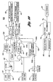
- FIG. 1 is a schematic view of an exemplary embodiment of an engine system including an exemplary control subsystem
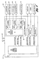
- FIG. 2 is a block diagram of the exemplary control subsystem of the engine system of FIG. 1 ;
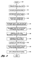
- FIG. 3 is a flow chart of an exemplary method of EGR control that may be used with the engine system of FIG. 1 ;
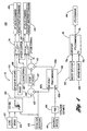
- FIG. 4 is a block diagram illustrating a preferred control flow portion of the method of FIG. 3 and including a total EGR estimation block and high and low pressure EGR open-loop control blocks;
- FIGS. 5A-5C illustrate exemplary embodiments of the estimation block of FIG. 4 ;
- FIGS. 6A-6B illustrate exemplary embodiments of the high and low pressure EGR open-loop control blocks of FIG. 4 ;
- FIG. 7 is a graph illustrating an exemplary plot of valve position versus target total EGR fraction
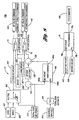
- FIG. 8 is a block diagram illustrating a second control flow portion of the method of FIG. 3 ;
- FIG. 9 a block diagram illustrating a third control flow portion of the method of FIG. 3 ;
- FIG. 10 is a block diagram illustrating a fourth control flow portion of the method of FIG. 3 .
- exhaust gas recirculation is controlled in a turbocharged engine system having high pressure (HP) and low pressure (LP) EGR paths.
- total EGR fraction is estimated responsive to a proxy parameter as input to one or more engine system models, and is not directly measured by HP or LP EGR flow sensors or a total EGR flow sensor.
- a target total EGR fraction is determined for compliance with exhaust emissions criteria.
- a target HP/LP EGR ratio is determined for optimization of other criteria, such as at least one of fuel economy targets, engine system performance goals, or engine system protection or maintenance specifications, within the constraints of the determined target total EGR fraction.
- the target total EGR fraction is closed-loop controlled by closed-loop adjustments to the HP and/or LP EGR fractions.
- FIG. 1 An exemplary operating environment is illustrated in FIG. 1 , and may be used to implement a presently disclosed method of EGR control.
- the method may be carried out using any suitable system and, preferably, is carried out in conjunction with an engine system such as system 10.
- an engine system such as system 10.
- the following system description simply provides a brief overview of one exemplary engine system, but other systems and components not shown here could also support the presently disclosed method.
- the system 10 may include an internal combustion engine 12 to develop mechanical power from internal combustion of a mixture of fuel and induction gases, an induction subsystem 14 to generally provide the induction gases to the engine 12 and, an exhaust subsystem 16 to convey combustion gases generally away from the engine 12.
- the phrase induction gases may include fresh air and recirculated exhaust gases.
- the system 10 also generally may include a turbocharger 18 in communication across the exhaust and induction subsystems 14, 16 to compress inlet air to improve combustion and thereby increase engine output.
- the system 10 further generally may include an exhaust gas recirculation subsystem 20 across the exhaust and induction subsystems 14, 16 to recirculate exhaust gases for mixture with fresh air to improve emissions performance of the engine system 10.
- the system 10 further generally may include a control subsystem 22 to control operation of the engine system 10.
- a control subsystem 22 to control operation of the engine system 10.
- a fuel subsystem (not shown) is used to provide any suitable liquid and/or gaseous fuel to the engine 12 for combustion therein with the induction gases.
- the internal combustion engine 12 may be any suitable type of engine, such as an autoignition or compression-ignition engine like a diesel engine.
- the engine 12 may include a block 24 with cylinders and pistons therein (not separately shown), which along with a cylinder head (also not separately shown), define combustion chambers (not shown) for internal combustion of a mixture of fuel and induction gases.
- the induction subsystem 14 may include, in addition to suitable conduit and connectors, an inlet end 26 which may have an air filter (not shown) to filter incoming air, and a turbocharger compressor 28 downstream of the inlet end 26 to compress the inlet air.
- the induction subsystem 14 may also include a charge air cooler 30 downstream of the turbocharger compressor 28 to cool the compressed air, and an intake throttle valve 32 downstream of the charge air cooler 30 to throttle the flow of the cooled air to the engine 12.
- the induction subsystem 14 also may include an intake manifold 34 downstream of the throttle valve 32 and upstream of the engine 12, to receive the throttled air and distribute it to the engine combustion chambers.
- the exhaust subsystem 16 may include, in addition to suitable conduit and connectors, an exhaust manifold 36 to collect exhaust gases from the combustion chambers of the engine 12 and convey them downstream to the rest of the exhaust subsystem 16.
- the exhaust subsystem 16 also may include a turbocharger turbine 38 in downstream communication with the exhaust manifold 36.
- the turbocharger 18 may be a variable turbine geometry (VTG) type of turbocharger, a dual stage turbocharger, or a turbocharger with a wastegate or bypass device, or the like.
- VGT variable turbine geometry
- the turbocharger 18 and/or any turbocharger accessory device(s) may be adjusted to affect any one or more of the following parameters: turbocharger boost pressure, air mass flow, and/or EGR flow.
- the exhaust subsystem 16 may also include any suitable emissions device(s) 40 such as a catalytic converter like a close-coupled diesel oxidation catalyst (DOC) device, a nitrogen oxide (NOx) adsorber unit, a particulate filter, or the like.
- the exhaust subsystem 16 may also include an exhaust throttle valve 42 disposed upstream of an exhaust outlet 44.
- the EGR subsystem 20 is preferably a hybrid or dual path EGR subsystem to recirculate portions of the exhaust gases from the exhaust subsystem 16 to the induction subsystem 14 for combustion in the engine 12.
- the EGR subsystem 20 may include two paths: a high pressure (HP) EGR path 46 and a low pressure (LP) EGR path 48.
- HP EGR path 46 is connected to the exhaust subsystem 16 upstream of the turbocharger turbine 38 but connected to the induction subsystem 12 downstream of the turbocharger compressor 28.
- the LP EGR path 48 is connected to the exhaust subsystem 16 downstream of the turbocharger turbine 38 but connected to the induction subsystem 14 upstream of the turbocharger compressor 28.
- Any other suitable connection between the exhaust and induction sub-systems 14, 16 is also contemplated including other forms of HP EGR such as the usage of internal engine variable valve timing and lift to induce internal HP EGR.
- the HP EGR path 46 may include, in addition to suitable conduit and connectors, an HP EGR valve 50 to control recirculation of exhaust gases from the exhaust subsystem 16 to the induction subsystem 14.
- the HP EGR valve 50 may be a stand-alone device having its own actuator or may be integrated with the intake throttle valve 32 into a combined device having a common actuator.
- the HP EGR path 46 may also include an HP EGR cooler 52 upstream, or optionally downstream, of the HP EGR valve 50 to cool the HP EGR gases.
- the HP EGR path 46 is preferably connected upstream of the turbocharger turbine 38 and downstream of the throttle valve 32 to mix HP EGR gases with throttled air and other induction gases (the air may have LP EGR).
- the LP EGR path 48 may include, in addition to suitable conduit and connectors, an LP EGR valve 54 to control recirculation of exhaust gases from the exhaust subsystem 16 to the induction subsystem 14.
- the LP EGR valve 54 may be a stand-alone device having its own actuator or may be integrated with the exhaust throttle valve 42 into a combined device having a common actuator.
- the LP EGR path 48 may also include an LP EGR cooler 56 downstream, or optionally upstream, of the LP EGR valve 54 to cool the LP EGR gases.
- the LP EGR path 48 is preferably connected downstream of the turbocharger turbine 38 and upstream of the turbocharger compressor 28 to mix LP EGR gases with filtered inlet air.
- control subsystem 22 may include any suitable hardware, software, and/or firmware to carry out at least some portions of the methods disclosed herein.
- control subsystem 22 may include some or all of the engine system actuators 58 discussed above, as well as various engine sensors 60.
- the engine system sensors 60 are not individually shown in the drawings but may include any suitable devices to monitor engine system parameters.
- an engine speed sensor measures the rotational speed of an engine crankshaft (not shown)
- pressure sensors in communication with the engine combustion chambers measure engine cylinder pressure
- intake and exhaust manifold pressure sensors measure pressure of gases flowing into and away from the engine cylinders
- an inlet air mass flow sensor measures incoming airflow in the induction subsystem 14
- a manifold mass flow sensor measures flow of induction gases to the engine 12.
- the engine system 10 may include a temperature sensor to measure the temperature of induction gases flowing to the engine cylinders, and a temperature sensor downstream of the air filter and upstream of the turbocharger compressor 28.
- the engine system 10 may include a speed sensor suitably coupled to the turbocharger compressor 28 to measure the rotational speed thereof.
- a throttle position sensor such as an integrated angular position sensor, measures the position of the throttle valve 32.
- a position sensor is disposed in proximity to the turbocharger 18 to measure the position of the variable geometry turbine 38.
- a tailpipe temperature sensor may be placed just upstream of a tailpipe outlet to measure the temperature of the exhaust gases exiting the exhaust subsystem 16.
- temperature sensors are placed upstream and downstream of the emissions device(s) 40 to measure the temperature of exhaust gases at the inlet(s) and outlet(s) thereof.
- one or more pressure sensors are placed across the emissions device(s) 40 to measure the pressure drop thereacross.
- An oxygen (O 2 ) sensor is placed in the exhaust and/or induction subsystems 14, 16, to measure oxygen in the exhaust gases and/or induction gases.
- position sensors measure the positions of the HP and LP EGR valves 50, 54 and the exhaust throttle valve 42.
- any other suitable sensors and their associated parameters may be encompassed by the presently disclosed system and methods.
- the sensors 60 could also include accelerator sensors, vehicle speed sensors, powertrain speed sensors, filter sensors, other flow sensors, vibration sensors, knock sensors, intake and exhaust pressure sensors, and/or the like.
- any sensors may be used to sense any suitable physical parameters including electrical, mechanical, and chemical parameters.
- the term sensor includes any suitable hardware and/or software used to sense any engine system parameter and/or various combinations of such parameters.
- the control subsystem 22 may further include one or more controllers (not shown) in communication with the actuators 58 and sensors 60 for receiving and processing sensor input and transmitting actuator output signals.
- the controller(s) may include one or more suitable processors and memory devices (not shown).
- the memory may be configured to provide storage of data and instructions that provides at least some of the functionality of the engine system 10 and that may be executed by the processor(s). At least portions of the method may be enabled by one or more computer programs and various engine system data or instructions stored in memory as look-up tables, maps, models, or the like.
- the control subsystem 22 controls engine system parameters by receiving input signals from the sensors 60, executing instructions or algorithms in light of sensor input signals, and transmitting suitable output signals to the various actuators 58.
- the control subsystem 22 may include several modules in the controller(s). For example, a top level engine control module 62 receives and processes any suitable engine system input signals and communicates output signals to an induction control module 64, a fuel control module 66, and any other suitable control modules 68. As will be discussed in greater detail below, the top level engine control module 62 receives and processes input signals from one or more of the engine system parameter sensors 60 to estimate total EGR fraction in any suitable manner.
- the total EGR fraction may be calculated using the fresh air mass flow sensor and induction gas mass flow from a sensor or from an estimate thereof, or using an estimate of total EGR fraction itself and the induction gas mass flow.
- the top level engine control module 62 may include suitable data inputs to estimate the total EGR fraction directly from one or more mass flow sensor measurements or estimations as input to one or more engine system models.
- model includes any construct that represents something using variables, such as a look up table, map, algorithms and/or the like. Models are application specific and particular to the exact design and performance specifications of any given engine system.
- the engine system models in turn may be based on engine speed and intake manifold pressure and temperature.
- the engine system models are updated each time engine parameters change, and may be multidimensional look up tables using inputs including engine speed and engine intake density, which may be determined with the intake pressure, temperature, and universal gas constant.
- the total EGR fraction may be correlated, directly or indirectly via its constituents, to one or more engine system parameters, such as estimated or sensed air mass flow, O 2 , or engine system temperature(s). Such parameters may be analyzed in any suitable fashion for correlation with the total EGR fraction.
- the total EGR fraction may be formulaically related to the other engine system parameters.
- the total EGR fraction may be empirically and statistically related to the other engine system parameters.
- that correlation may be modeled formulaically, empirically, acoustically, and/or the like.
- empirical models may be developed from suitable testing and may include lookup tables, maps, and the like that may cross reference total EGR fraction values with other engine system parameter values.
- an engine system parameter may be used as a proxy for direct sensor measurements of total EGR fraction and/or individual HP and/or LP EGR flow. Accordingly, total EGR, HP EGR, and LP EGR flow sensors may be eliminated, thereby saving on engine system cost and weight. Elimination of such sensors also leads to elimination of other sensor-related hardware, software, and costs, such as wiring, connector pins, computer processing power and memory, and so on.
- the top level engine control 62 module preferably calculates a turbocharger boost pressure setpoint and a target total EGR setpoint, and transmits these setpoints to the induction control module 64.
- the top level engine control module 62 calculates suitable timing and fueling setpoints and transmits them to the fuel control module 66, and calculates other setpoints and transmits them to the other control modules 68.
- the fuel and other control modules 66, 68 receive and process such inputs, and generate suitable command signals to any suitable engine system devices such as fuel injectors, fuel pumps, or other devices.
- the top level engine control module 62 may calculate and transmit the boost pressure setpoint and a total intake air mass flow setpoint (as shown in dashed lines), instead of the target total EGR setpoint.
- the total EGR setpoint is subsequently determined from the air mass flow setpoint in much the same way the actual total EGR fraction is estimated from the actual mass flow sensor readings.
- air mass flow replaces total EGR fraction throughout the control method. This changes the types of data used and the manner in which HP and LP EGR flow targets are set, but the basic structure of the controller and flow of the control method is the same.
- the induction control module 64 receives any suitable engine system parameter values, in addition to the setpoints received from the top level engine control module 62.
- the induction control module 64 receives induction and/or exhaust subsystem parameter values like turbocharger boost pressure, and mass flow.
- the induction control module 64 may include a top level induction control submodule 70 that processes the received parameter values, and transmits any suitable outputs such as LP and HP EGR setpoints, and turbocharger setpoints to respective LP EGR, HP EGR, and turbocharger control submodules 72, 74, 76.
- the LP EGR, HP EGR, and turbocharger control submodules 72, 74, 76 process such induction control submodule outputs and generate suitable command signals to various engine system devices such as the LP EGR valve 54 and exhaust throttle valve 42, HP EGR valve 50 and intake throttle valve 32, and one or more turbocharger actuators 19.
- the various modules and/or submodules may be separate as shown, or may be integrated into one or more combined modules and/or submodules.
- a method of controlling LP and HP EGR is provided herein and may be carried out as one or more computer programs within the operating environment of the engine system 10 described above. Those skilled in the art will also recognize that the method may be carried out using other engine systems within other operating environments. Referring now to FIG. 3 , an exemplary method 300 is illustrated in flow chart form.
- the method 300 may be initiated in any suitable manner.
- the method 300 may be initiated at startup of the engine 12 of the engine system 10 of FIG. 1 .
- fresh air is drawn into an induction subsystem of an engine system, and induction gases are inducted into an engine of the engine system through the induction subsystem.
- fresh air may be drawn into the inlet 26 of the induction system 14, and induction gases may be inducted into the engine 12 through the intake manifold 34.
- exhaust gases are exhausted from an engine through an exhaust subsystem of an engine system.
- exhaust gases may be exhausted from the engine 12 through the exhaust manifold 36.
- exhaust gases are recirculated from an exhaust subsystem through one or both of high or low pressure EGR paths to an induction subsystem of an engine system.
- HP and LP exhaust gases may be recirculated from the exhaust subsystem 16, through the HP and LP EGR paths 46, 48, to the induction subsystem 14.
- one or more proxy parameters may be sensed that is/are indicative of total EGR fraction.
- the proxy parameter(s) may include air mass flow, O 2 , and/or engine system temperatures, and may be measured by respective sensors 60 of the engine system 10.
- a target total EGR fraction is determined for compliance with exhaust emissions criteria.
- the top level engine control module 62 may use any suitable engine system model(s) to cross-reference current engine operating parameters with desirable total EGR fraction values to comply with predetermined emissions standards.
- target includes a single value, multiple values, and/or any range of values.
- criteria includes the singular and the plural. Examples of criteria used to determine appropriate EGR fraction(s) include calibrated tables based on speed and load, model based approaches which determine cylinder temperatures targets and convert to EGR fraction and operating conditions such as transient operation or steady state operation. Absolute emissions criteria may be dictated by environmental entities such as the U.S. Environmental Protection Agency (EPA).
- EPA U.S. Environmental Protection Agency
- a target HP/LP EGR ratio is determined to optimize one or more other engine system criteria such as fuel economy goals, engine system performance goals, or engine system protection or maintenance specifications, and as constrained by the target total EGR fraction determined in step 330.
- individual HP EGR and/or LP EGR setpoints may be generated in accordance with the target HP/LP EGR ratio determined in step 335.
- target HP and LP EGR opening percentages corresponding to the HP and LP EGR setpoints may be determined.
- open-loop controllers may process the HP and LP EGR setpoints and other engine system parameters using models to generate the opening percentages.
- total EGR fraction may be estimated responsive to the proxy parameter(s), which are used as input to any suitable engine system models as discussed previously above.
- the total EGR fraction estimate may include engine system models to formulaically or empirically correlate the proxy parameter(s) to the total EGR fraction.
- the models may include lookup tables, maps, and the like, that may cross reference EGR fraction values with proxy parameter values, and may be based on engine speed and intake manifold pressure and temperature.
- the total EGR fraction is not actually directly measured using individual HP and/or LP EGR flow sensors or a combined total EGR flow sensor.
- one or both of the individual HP EGR and/or LP EGR fractions may be adjusted using closed-loop control with the estimated total EGR fraction.
- the HP and/or LP EGR fractions may be adjusted via closed-loop control of either or both of the respective HP and/or LP EGR setpoints or the valve and/or throttle opening percentages.
- a closed-loop controller may process the estimated total EGR fraction as process variable input and the total EGR fraction setpoint as a setpoint input, in order to generate an HP and/or LP EGR setpoint output trim command.
- the target total EGR fraction preferably is closed-loop controlled by closed-loop adjustments to the HP and/or LP EGR fractions. Such adjustments may change the actual HP/LP EGR ratio.
- the HP EGR and LP EGR opening percentages from step 350 may be applied to one or more respective HP EGR, LP EGR, intake throttle, or exhaust throttle valves.
- the HP and/or LP EGR opening percentages are adjusted directly, downstream of the open-loop control blocks or indirectly via setpoint adjustment upstream of the open-loop control blocks.
- FIG. 4 a portion of the control method 300 from FIG. 3 is illustrated in block form as an EGR control flow 400.
- the control flow 400 may be carried out, for example, within the exemplary control subsystem of FIG. 2 and, more particularly, within the induction control module 64 thereof.
- FIG. 4 illustrates the HP and LP EGR control submodules or blocks 72, 74 and the turbocharger boost control submodule or block 76.
- an optimization block 402 an EGR fraction estimator block 404, and an EGR fraction closed-loop control block 406 may also be carried out within the induction control module 64 and, more particularly, within the top level induction control submodule 70 of FIG. 2 .
- the actual total EGR fraction estimator block 404 is preferably carried out using the proxy parameter(s) for the actual total EGR fraction in addition to other standard engine system parameters such as engine load, engine speed, turbocharger boost pressure, and engine system temperatures.
- the preferred proxy parameter is air mass flow 414a, which may be obtained from any suitable air mass flow estimate or reading such as from the intake air mass flow sensor.
- FIG. 5B illustrates that the proxy parameter may be oxygen percentage 414b, such as from an O 2 sensor like the O 2 sensor disposed in the induction subsystem 14.
- the O 2 sensor may be a universal exhaust gas oxygen sensor (UEGO), which may be located in the intake manifold 34.
- UEGO universal exhaust gas oxygen sensor
- FIG. 5C illustrates that the proxy parameter may be induction subsystem and exhaust subsystem temperature 414c taken from temperature sensors.
- inlet air temperature may be used such as from the air inlet temperature sensor, exhaust temperature such as from the exhaust temperature sensor, and manifold temperature such as from the intake manifold temperature sensor.
- the actual total EGR fraction 416 may be estimated from one or more proxy parameter types.
- the optimization block 402 receives and processes various engine system inputs to identify an optimal HP/LP EGR ratio and generate an HP EGR setpoint according to that ratio.
- the optimization block 402 may receive the engine load signal 407 and the engine speed signal 408, such as from corresponding sensors in the engine system 10.
- the engine load signal 407 may include any parameters such as manifold pressure, fuel injection flow, etc.
- the optimization block 402 may also receive a total EGR fraction setpoint 418 such as from the top level engine control module 62.
- the optimization block 402 may prioritize fuel economy criteria for identifying the optimal HP/LP EGR ratio and generating the corresponding HP EGR setpoint.
- the optimization block 402 may include any suitable net turbocharger efficiency model that encompasses various parameters such as pumping losses, and turbine and compressor efficiencies.
- the efficiency model may include a principles based mathematical representation of the engine induction subsystem 14, a set of engine system calibration tables, or the like.
- Example criteria used to determine desired EGR ratios to meet fuel economy criteria may include setting a ratio that allows the total EGR fraction to be achieved without the need for closing the intake or exhaust throttles, which closing tends to negatively impact fuel economy, or the ratio may be adjusted to achieve an optimal induction air temperature for maximum fuel economy.
- the optimization block 402 may also override the fuel economy criteria to instead optimize other engine system criteria for any suitable purpose.
- the fuel economy criteria may be overridden to provide an HP/LP EGR ratio that provides improved engine system performance, such as increased torque output in response to driver demand for vehicle acceleration.
- the controller may favor a higher percentage of LP EGR which allows better turbocharger speed-up to reduce turbo lag.
- the override may provide a different HP/LP EGR ratio to protect the engine system 10 such as to avoid a turbocharger overspeed condition or excess compressor tip temperatures, or to reduce turbocharger condensate formation, or the like.
- the override may provide another HP/LP EGR ratio to maintain the engine system 10 such as by affecting induction or exhaust subsystem temperatures.
- exhaust subsystem temperatures may be increased to regenerate a diesel particulate filter, and induction temperatures may be reduced to cool the engine 12.
- induction air temperature may be controlled to reduce the potential for water condensate to form in the inlet induction path.
- the optimization block 402 processes the inputs in accordance with its model(s) to determine the target HP/LP EGR ratio and then generate an HP EGR setpoint 420, which is fed downstream to the HP EGR control block 74 and to an arithmetic node 422, which also receives the total EGR fraction setpoint 418 from the top level engine control module 62 to yield an LP EGR setpoint 424.
- the total EGR fraction closed-loop control block 406 may be any suitable closed-loop control means, such as a PID controller block or the like, for controlling the total EGR fraction.
- the closed-loop control block 406 includes a setpoint input 406a to receive the target total EGR fraction setpoint from the top level engine control module 62 and further may include a process variable input 406b to receive the actual total EGR fraction estimate from the estimator block 404.
- the total EGR fraction control block 406 processes these inputs to generate a feedback control signal or trim command 406c for summation at another arithmetic node 426 with the LP EGR setpoint 424 for input downstream at the LP EGR control block 72.
- trim adjustment may also or instead be calculated as an adjustment to the LP EGR valve and/or exhaust throttle valve percentage opening command(s) and added after the LP EGR open-loop control block 72. Accordingly, the control block 406 and associate nodes would be communicated to the open-loop control block 72 at a downstream side thereof to adjust suitable setpoints for the valve and throttle opening percentages.
- the LP EGR flow or fraction is adjusted by the closed-loop control block 406 to achieve the target total EGR fraction. More specifically, because exhaust emissions and engine fuel economy are both highly dependent on total EGR fraction and to a lesser extent on the HP/LP EGR ratio, the total EGR fraction is closed-loop controlled for maximum control whereas the HP and/or LP EGR fractions and/or the HP/LP EGR ratio is/are at least partially open-loop controlled for maximum cost-effectiveness and efficiency.
- These open-loop control blocks 72, 74 provide good response time, reduce controller interdependencies, and reduce the effects of transients and disturbances in sensor signals. While this is one exemplary approach, other approaches are discussed below in reference to FIGS. 8-10 .
- the LP and HP EGR control blocks 72, 74 receive their respective LP and HP EGR setpoints in addition to the turbocharger boost pressure 409 and the engine load and speed inputs 407, 408.
- the LP and HP EGR control blocks 72, 74 receive such inputs for open-loop or feedforward control of their respective LP and HP EGR actuators.
- the LP and HP EGR control blocks 72, 74 output LP EGR valve and/or exhaust throttle commands 430, 432, and HP EGR valve and/or intake throttle commands 438, 440.
- the LP and HP EGR control blocks 72, 74 may correlate HP and LP EGR flow to suitable HP and LP EGR valve and/or throttle positions using one or more models.
- the LP and HP EGR control blocks 72, 74 may include various open-loop control models.
- the LP EGR control block 72 may include any suitable model(s) 426 to correlate the LP EGR setpoint 424 to the LP EGR valve position to help achieve the target HP/LP EGR ratio.
- the LP EGR control block 72 may include any suitable model(s) 428 to correlate the LP EGR setpoint 424 to the exhaust throttle position to help achieve the target HP/LP EGR ratio.
- the models 426, 428 may receive any suitable inputs such as the engine load 407, the engine speed 408, and the turbocharger boost pressure 409.
- the models 426, 428 are executed to generate, respectively, the LP EGR valve command 430 and/or the exhaust throttle command 432 for use by respective actuators.
- the actuators may operate in an open loop mode, or may be operatively coupled with any suitable sensors to measure actuator position and adjust the commands to achieve the target percentages.
- the HP EGR control block 74 may include any suitable model(s) 434 to correlate the HP EGR setpoint 420 to the HP EGR valve position to help achieve the target HP/LP EGR ratio.
- the HP EGR control block 74 may include any suitable model(s) 436 to correlate the HP EGR setpoint 420 to the intake throttle position to help achieve the target HP/LP EGR ratio.
- the models 434, 436 may receive any suitable inputs such as the engine load 407, the engine speed 408, and the turbocharger boost pressure 409. The models 434, 436 are executed to generate, respectively, an HP EGR valve command 438 and/or an intake throttle command 440 for use by respective actuators.
- FIG. 7 illustrates a graph of exemplary LP EGR valve and exhaust throttle opening percentages vs. target total EGR fraction.
- the throttle valve 42 may be substantially closed at about 0% EGR and gradually opens to a substantially 100% open position at about 20% EGR, whereas the LP EGR valve 54 stays substantially closed from about 0% EGR to about 20% EGR. Thereafter, the exhaust throttle 42 stays 100% open until the total EGR reaches about 70%, and the LP EGR valve 54 gradually opens to substantially 100% open at about 70% EGR. Thereafter, the LP EGR valve 54 remains substantially 100% open, while the exhaust throttle valve 42 gradually closes until it is substantially closed at 100% EGR.
- a single, combined, LP EGR and exhaust throttle valve could be used instead of two separate valves as long as such a unitary valve device could substantially achieve the valve openings just described.
- the turbocharger boost control block 76 is any suitable closed-loop control means, such as suitable PID control block, for adjusting turbocharger actuators to achieve a target boost pressure within safe turbo operating boundaries.
- the control block 76 may include a setpoint input 76a to receive boost setpoint from the top level engine control module 62, and an actual boost pressure input 76b from the turbocharger boost sensor.
- the control block 76 processes these inputs and generates any suitable turbocharger command output such as a variable turbine geometry command 444 to adjust variable vanes of the turbocharger 18.
- an alternative control flow 800 may be used in place of the preferred control flow 400.
- This embodiment is similar in many respects to the embodiment of FIG. 4 , and like numerals between the embodiments generally designate like or corresponding elements throughout the several views of the drawing figures. Additionally, the description of the previous embodiment is incorporated by reference and the common subject matter may generally not be repeated here.
- the alternative control flow 800 involves closed-loop adjustment of HP EGR instead of LP EGR.
- an HP EGR setpoint 420' - instead of an LP EGR setpoint 424' - may be adjusted to control the total EGR fraction.
- the closed-loop control block 406 may generate a control signal to adjust the HP EGR fraction - instead of the LP EGR fraction.
- an optimization block 402' may be provided to output an LP EGR setpoint 424' instead of the HP EGR setpoint 420.
- trim adjustment may also or instead be calculated as an adjustment to the HP EGR valve and/or intake throttle valve percentage opening command(s) and added after the HP EGR open-loop control block 74. Accordingly, the control block 406 and associate nodes would be communicated to the open-loop control block 74 at a downstream side thereof to adjust suitable setpoints for the valve and throttle opening percentages. Otherwise, the flow 800 is substantially similar to flow 400.
- a second control flow 900 may be used in place of the preferred control flow 400.
- This embodiment is similar in many respects to the embodiment of FIG. 4 , and like numerals between the embodiments generally designate like or corresponding elements throughout the several views of the drawing figures. Additionally, the description of the previous embodiment is incorporated by reference and the common subject matter may generally not be repeated here.
- closed-loop control may be allocated to HP and LP EGR fractions in the same proportion as the HP and LP EGR setpoints.
- HP and LP EGR fractions are both closed-loop adjusted in proportion to their respective HP and LP EGR setpoints.
- the closed-loop control block 406 does not output its trim command 406c only to the LP EGR control block 72 via the upstream arithmetic node 426 as in flow 400. Rather, the trim command is output to both the LP and HP EGR control blocks 72, 74.
- proportional arithmetic blocks 950, 952 receive respective HP and LP EGR setpoints and the total EGR setpoint 418. The proportional output from the arithmetic blocks 950, 952 is received at multiplication arithmetic blocks 954, 956 for proportional allocation of the closed-loop trim command 406c thereto.
- the multiplication outputs are summed at downstream arithmetic nodes 426, 926 with the LP and HP EGR setpoints for input downstream at the LP and HP EGR control blocks 72, 74. Suitable checks could be implemented within the arithmetic blocks to avoid dividing by 0 when the total EGR fraction set-point is 0. Otherwise the flow 900 is substantially similar to that in flows 400 and/or 800.
- a third exemplary control flow 1000 may be used in place of the preferred control flow 400.
- This embodiment is similar in many respects to the embodiment of FIG. 4 , and like numerals between the embodiments generally designate like or corresponding elements throughout the several views of the drawing figures. Additionally, the description of the previous embodiment is incorporated by reference and the common subject matter may generally not be repeated here.
- closed-loop control may be switched back and forth between the LP and HP EGR open-loop control blocks 72, 74 depending on engine operating conditions at any given moment.
- either HP or LP EGR setpoints may be adjusted with closed-loop control.
- HP EGR may be closed-loop controlled to avoid turbocharger condensation when engine system temperatures are relatively high, or when a rapid change in total EGR fraction is required, or when the turbocharger performance is less important or not required.
- a closed-loop control block 1006 does not provide output only to the LP EGR control block 72 via the upstream arithmetic node 426 as in flow 400. Rather, the control block 1006 provides output to both the LP and HP EGR control blocks 72, 74.
- the closed-loop control block 1006 may include a setpoint input 1006a to receive the target total EGR fraction setpoint 418 from the top level engine control module 62 and further may include a process variable input 1006b to receive the actual total EGR fraction estimate from the estimator block 404.
- the total EGR fraction control block 1006 processes these inputs to generate alternative trim commands; an LP EGR trim command 1006c for summation at arithmetic node 426 with the LP EGR setpoint 424 for input downstream at the LP EGR control block 72, and an HP EGR trim command 1006d for summation at another arithmetic node 1026 with the HP EGR setpoint 420 for input downstream at the HP EGR control block 74.
- the control block 1006 may be switched between the two outputs 1000c, 1000d such that the LP EGR fraction or the HP EGR fraction may be adjusted by the closed-loop control block 1006 to achieve the target total EGR fraction. Otherwise, the flow 1000 is substantially similar to that in flows 400 and/or 800.
- a total target EGR fraction may be allocated to HP and LP EGR paths in a manner to first comply with emissions regulations, and then to optimize engine fuel economy and performance and protect and maintain an engine system.
- Third, one standard closed-loop control means may be used to control a target total EGR fraction as well as the individual HP and LP EGR flows, thereby allowing practical and cost-effective implementation in current engine control architectures.
- a combined LP EGR valve and exhaust throttle valve controlled by a single common actuator may be used and, likewise, a combined HP EGR valve and intake throttle valve controlled by a single common actuator may also be used.
- a method of controlling exhaust gas recirculation (EGR) in a turbocharged compression-ignition engine system including an engine, an induction subsystem in upstream communication with the engine, an exhaust subsystem in downstream communication with the engine and including an exhaust throttle valve, a high pressure EGR path between the exhaust and induction subsystems upstream of a turbocharger turbine and downstream of a turbocharger compressor and including an HP EGR valve, and a low pressure EGR path between the exhaust and induction subsystems downstream of the turbocharger turbine and upstream of the turbocharger compressor and including an LP EGR valve, the method comprising:
- the proxy parameter(s) may include at least one of air mass flow, O 2 , or engine system temperatures.
- the the total EGR fraction estimating step may include using the engine system model(s) to formulaically or empirically correlate the proxy parameter(s) to the total EGR fraction.
- the engine system model(s) may include at least one of lookup tables or maps that cross reference EGR fraction values with proxy parameter values.
- the engine system model(s) may be based on engine speed and intake manifold pressure and temperature.
- Determining the target HP/LP EGR ratio may include overriding the fuel economy criteria in favor of other engine system criteria, within the constraints of the determined target total EGR fraction.
- the other engine system criteria may include engine system performance.
- the other engine system criteria may further include at least one of engine system protection or maintenance specifications.
- the LP EGR valve may include an intake throttle valve, wherein the valves are operated by a common actuator.
- the HP EGR valve may include an exhaust throttle valve, wherein the valves are operated by a common actuator.
- Determining a target HP/LP EGR ratio may include using a turbocharger efficiency model.
- Determining target HP and LP EGR opening percentages includes using open-loop models with engine load, engine speed, and turbocharger boost pressure as inputs.
- the opening percentages may be applied such that the exhaust throttle valve is substantially closed at about 0% EGR and gradually opens to a substantially 100% open position at about 20% EGR, whereas the LP EGR valve stays substantially closed from about 0% EGR to about 20% EGR and, thereafter, the exhaust throttle valve stays substantially 100% open until total EGR reaches about 70%, and the LP EGR valve gradually opens to substantially 100% open at about 70% EGR, whereafter the LP EGR valve remains substantially 100% open, while the exhaust throttle valve gradually closes until it is substantially closed at about 100% EGR.
- a method of controlling exhaust gas recirculation (EGR) in a turbocharged compression-ignition engine system including an engine, an induction subsystem in upstream communication with the engine, an exhaust subsystem in downstream communication with the engine, a high pressure EGR path between the exhaust and induction subsystems upstream of a turbocharger turbine and downstream of a turbocharger compressor and including an HP EGR valve, and a low pressure EGR path between the exhaust and induction subsystems downstream of the turbocharger turbine and upstream of the turbocharger compressor and including an LP EGR valve, the method comprising:
Applications Claiming Priority (2)
| Application Number | Priority Date | Filing Date | Title |
|---|---|---|---|
| US75241505P | 2005-12-20 | 2005-12-20 | |
| EP06848058A EP1963646B1 (en) | 2005-12-20 | 2006-12-20 | Controlling exhaust gas recirculation in a turbocharged compression-ignition engine system |
Related Parent Applications (1)
| Application Number | Title | Priority Date | Filing Date |
|---|---|---|---|
| EP06848058.1 Division | 2006-12-20 |
Publications (2)
| Publication Number | Publication Date |
|---|---|
| EP2292915A1 EP2292915A1 (en) | 2011-03-09 |
| EP2292915B1 true EP2292915B1 (en) | 2013-07-24 |
Family
ID=38068892
Family Applications (3)
| Application Number | Title | Priority Date | Filing Date |
|---|---|---|---|
| EP10187695.1A Expired - Fee Related EP2292913B1 (en) | 2005-12-20 | 2006-12-20 | Controlling exhaust gas recirculation in a turbocharged engine system |
| EP06848058A Expired - Fee Related EP1963646B1 (en) | 2005-12-20 | 2006-12-20 | Controlling exhaust gas recirculation in a turbocharged compression-ignition engine system |
| EP10180664.4A Expired - Fee Related EP2292915B1 (en) | 2005-12-20 | 2006-12-20 | Controlling exhaust gas recirculation in turbocharged engine systems |
Family Applications Before (2)
| Application Number | Title | Priority Date | Filing Date |
|---|---|---|---|
| EP10187695.1A Expired - Fee Related EP2292913B1 (en) | 2005-12-20 | 2006-12-20 | Controlling exhaust gas recirculation in a turbocharged engine system |
| EP06848058A Expired - Fee Related EP1963646B1 (en) | 2005-12-20 | 2006-12-20 | Controlling exhaust gas recirculation in a turbocharged compression-ignition engine system |
Country Status (7)
| Country | Link |
|---|---|
| US (1) | US10132230B2 (zh) |
| EP (3) | EP2292913B1 (zh) |
| JP (2) | JP5525162B2 (zh) |
| KR (3) | KR101551815B1 (zh) |
| CN (1) | CN101331302B (zh) |
| DE (1) | DE602006018996D1 (zh) |
| WO (1) | WO2007076038A2 (zh) |
Families Citing this family (104)
| Publication number | Priority date | Publication date | Assignee | Title |
|---|---|---|---|---|
| US20080261233A1 (en) | 2004-10-20 | 2008-10-23 | Peas Institut Ab | Assessment of Biological Activity of Hepatocyte Growth Factor (Hgf) |
| JP5525162B2 (ja) | 2005-12-20 | 2014-06-18 | ボーグワーナー インコーポレーテッド | ターボチャージャ付き圧縮着火エンジンシステムにおける排気ガス再循環制御方法 |
| US8630787B2 (en) | 2005-12-20 | 2014-01-14 | Borgwarner Inc. | Controlling exhaust gas recirculation in a turbocharged engine system |
| JP4218702B2 (ja) | 2006-06-22 | 2009-02-04 | トヨタ自動車株式会社 | 内燃機関の排気還流装置 |
| JP4816309B2 (ja) * | 2006-08-01 | 2011-11-16 | トヨタ自動車株式会社 | 内燃機関の排気再循環装置 |
| JP2009008463A (ja) * | 2007-06-27 | 2009-01-15 | Hitachi Ltd | 排気ガス再循環ガス流量測定装置および測定方法 |
| JP4380754B2 (ja) * | 2007-09-21 | 2009-12-09 | トヨタ自動車株式会社 | 内燃機関の排気還流装置 |
| FR2922268B1 (fr) * | 2007-10-10 | 2012-09-28 | Valeo Sys Controle Moteur Sas | Moteur a essence a circuit egr basse pression |
| FR2923544B1 (fr) * | 2007-11-09 | 2014-08-29 | Renault Sas | Moteur a combustion interne du type diesel suralimente et procede de commande du debit d'air et du taux de gaz d'echappement recycle dans un tel moteur |
| JP4905327B2 (ja) * | 2007-11-13 | 2012-03-28 | トヨタ自動車株式会社 | 内燃機関の排気浄化システム |
| FR2924757A1 (fr) * | 2007-12-10 | 2009-06-12 | Renault Sas | Procede de controle d'un moteur a combustion interne |
| US7848872B2 (en) * | 2007-12-20 | 2010-12-07 | Gm Global Technology Operations, Inc. | Method and apparatus for monitoring recirculated exhaust gas in an internal combustion engine |
| WO2009088506A1 (en) * | 2008-01-08 | 2009-07-16 | Mack Trucks, Inc. | Method for reducing diesel engine emissions, and diesel engine |
| CN103233809B (zh) * | 2008-01-08 | 2015-05-20 | 马克卡车公司 | 用于减少柴油发动机排放的方法及柴油发动机 |
| DE102008008721A1 (de) * | 2008-02-12 | 2009-08-20 | Knorr-Bremse Systeme für Nutzfahrzeuge GmbH | Verfahren und Vorrichtung zum Versorgen eines Kompressors mit Druckluft bei einer Verbrennungskraftmaschine |
| FR2928182A3 (fr) * | 2008-02-28 | 2009-09-04 | Renault Sas | Procede de controle du debit d'air d'un moteur automobile diesel suralimente par turbocompresseur et dispositif correspondant. |
| US8109091B2 (en) * | 2008-05-22 | 2012-02-07 | GM Global Technology Operations LLC | Exhaust gas recirculation control systems and methods |
| JP5613661B2 (ja) * | 2008-06-02 | 2014-10-29 | ボーグワーナー インコーポレーテッド | ターボチャージャ付きエンジンシステムの複数の通路によって排気ガス再循環を制御する方法 |
| US20110208409A1 (en) * | 2008-08-01 | 2011-08-25 | David Benjamin Snyder | Fuel blend sensing system |
| US8521354B2 (en) * | 2008-08-12 | 2013-08-27 | Southwest Research Institute | Diagnosis of sensor failure in airflow-based engine control system |
| JP4818344B2 (ja) * | 2008-11-25 | 2011-11-16 | 本田技研工業株式会社 | 内燃機関の過給圧制御装置 |
| KR101126233B1 (ko) * | 2008-12-05 | 2012-03-19 | 기아자동차주식회사 | Egr 시스템 및 그 제어방법 |
| JP5519767B2 (ja) | 2009-03-18 | 2014-06-11 | ボーグワーナー インコーポレーテッド | 外部egr混合のノック応答調整 |
| DE102009027137A1 (de) * | 2009-06-24 | 2010-12-30 | Ford Global Technologies, LLC, Dearborn | Verfahren und Vorrichtung zum Regeln der Strömungsrate einer Abgasrückführung in einem Verbrennungsmotor |
| US8286616B2 (en) * | 2009-06-29 | 2012-10-16 | GM Global Technology Operations LLC | Condensation control systems and methods |
| DE102009036743A1 (de) * | 2009-08-08 | 2011-02-10 | Daimler Ag | Verbrennungskraftmaschine |
| JP4844691B2 (ja) * | 2009-08-28 | 2011-12-28 | トヨタ自動車株式会社 | Egrシステムの異常検出装置及び異常検出方法 |
| US8010276B2 (en) * | 2009-08-31 | 2011-08-30 | International Engine Intellectual Property Company, Llc | Intake manifold oxygen control |
| CN102575620B (zh) | 2009-09-03 | 2014-06-18 | 丰田自动车株式会社 | 内燃机的排气再循环装置 |
| US8103427B2 (en) * | 2009-09-25 | 2012-01-24 | Cummins Inc. | EGR flow compensation for a diesel air handling system |
| US8635852B2 (en) * | 2009-09-29 | 2014-01-28 | Ford Global Technologies, Llc | Exhaust treatment system for internal combustion engine |
| GB2475274B (en) * | 2009-11-12 | 2016-06-15 | Gm Global Tech Operations Llc | Device and method for compressor and charge air cooler protection in an internal combustion engine |
| CN104806327B (zh) * | 2009-12-08 | 2017-08-04 | 丰田自动车株式会社 | 内燃机的排气净化系统 |
| CN102597466B (zh) * | 2009-12-18 | 2014-11-26 | 本田技研工业株式会社 | 内燃机的控制装置 |
| JP5506376B2 (ja) * | 2009-12-25 | 2014-05-28 | 株式会社堀場製作所 | Egr率測定装置 |
| BR112012019061A2 (pt) * | 2009-12-31 | 2020-09-15 | Purdue Research Foundation | métodos para controlar um motor de combustão interna |
| US7987837B2 (en) * | 2010-02-16 | 2011-08-02 | Ford Global Technologies, Llc | Exhaust treatment system for internal combustion engine |
| US20110225955A1 (en) * | 2010-02-17 | 2011-09-22 | Toyota Jidosha Kabushiki Kaisha | Exhaust apparatus for internal combustion engine |
| EP2546506B1 (en) * | 2010-03-09 | 2015-12-16 | Toyota Jidosha Kabushiki Kaisha | Control device for internal combustion engine |
| JP5376051B2 (ja) * | 2010-04-22 | 2013-12-25 | トヨタ自動車株式会社 | Egrシステムの異常検出装置及び異常検出方法 |
| CN102859173B (zh) * | 2010-04-22 | 2014-12-17 | 万国引擎知识产权有限责任公司 | 压燃发动机及分配来自压燃发动机的发动机排出尾气中的烟雾和NOx的方法 |
| US8769949B2 (en) | 2010-07-26 | 2014-07-08 | Vandyne Superturbo, Inc. | Superturbocharger control systems |
| US8042527B2 (en) * | 2010-08-05 | 2011-10-25 | Ford Global Technologies, Llc | Coordination of HP and LP EGR |
| US8602007B2 (en) * | 2010-09-17 | 2013-12-10 | GM Global Technology Operations LLC | Integrated exhaust gas recirculation and charge cooling system |
| US10316741B2 (en) | 2010-10-14 | 2019-06-11 | Ford Global Technologies, Llc | Turbocharged combustion system |
| US20120304639A1 (en) * | 2010-12-03 | 2012-12-06 | Cummins Intellectual Property, Inc. | Lean burn active ignition engine with aftertreatment system and method |
| KR101251513B1 (ko) * | 2010-12-06 | 2013-04-05 | 기아자동차주식회사 | Lp-egr이 적용된 엔진의 제어 방법 |
| US9217396B2 (en) | 2010-12-22 | 2015-12-22 | GM Global Technology Operations LLC | Boosting devices with integral features for recirculating exhaust gas |
| US9133793B2 (en) * | 2010-12-22 | 2015-09-15 | GM Global Technology Operations LLC | Boosting devices with integral features for recirculating exhaust gas |
| JP5907339B2 (ja) * | 2011-05-27 | 2016-04-26 | 株式会社デンソー | 内燃機関の筒内流入egrガス流量推定装置 |
| US9267449B2 (en) | 2011-06-16 | 2016-02-23 | GM Global Technology Operations LLC | Control system and method for coordinating throttle and boost |
| DE102011081634B4 (de) * | 2011-08-26 | 2021-06-10 | Robert Bosch Gmbh | Verfahren und Vorrichtung zur Diagnose eines Fehlers in einem Abgasrückführungssystem |
| CN102297047B (zh) * | 2011-08-30 | 2013-03-27 | 潍柴动力股份有限公司 | 用于二甲醚发动机的通道式egr系统和方法 |
| US9157390B2 (en) | 2011-09-21 | 2015-10-13 | GM Global Technology Operations LLC | Selective exhaust gas recirculation diagnostic systems and methods |
| DE102011084782B4 (de) * | 2011-10-19 | 2014-09-11 | Ford Global Technologies, Llc | Verfahren zum Betreiben einer aufgeladenen Brennkraftmaschine mit Abgasrückführung |
| KR101316863B1 (ko) * | 2011-12-09 | 2013-10-08 | 기아자동차주식회사 | 배기가스 재순환 진단 방법 및 시스템 |
| EP2623755A3 (en) * | 2012-01-31 | 2017-04-19 | International Engine Intellectual Property Company, LLC | Oxygen concentration setpoint modification |
| US9249764B2 (en) | 2012-03-06 | 2016-02-02 | GM Global Technology Operations LLC | Engine control systems and methods with humidity sensors |
| US10066564B2 (en) | 2012-06-07 | 2018-09-04 | GM Global Technology Operations LLC | Humidity determination and compensation systems and methods using an intake oxygen sensor |
| US9932917B2 (en) | 2012-03-21 | 2018-04-03 | GM Global Technology Operations LLC | Exhaust gas recirculation control systems and methods |
| EP2642103B1 (en) * | 2012-03-21 | 2014-11-19 | Ford Global Technologies, LLC | Exhaust-gas recirculation system and method for exhaust-gas recirculation |
| US20130268176A1 (en) * | 2012-04-05 | 2013-10-10 | GM Global Technology Operations LLC | Exhaust gas recirculation control systems and methods for low engine delta pressure conditions |
| DK177700B1 (en) * | 2012-04-19 | 2014-03-24 | Man Diesel & Turbo Deutschland | A large slow running turbocharged two stroke internal combustion engine with crossheads and exhaust- or combustion gas recirculation |
| US9528429B2 (en) * | 2012-05-17 | 2016-12-27 | Ford Global Technologies, Llc | Boost reservoir EGR control |
| ITBO20120489A1 (it) * | 2012-09-17 | 2014-03-18 | Magneti Marelli Spa | Metodo di controllo di un motore a combustione interna |
| ITBO20120488A1 (it) * | 2012-09-17 | 2014-03-18 | Magneti Marelli Spa | Metodo di controllo di un motore a combustione interna sovralimentato |
| DE102012022944A1 (de) * | 2012-11-24 | 2014-05-28 | Daimler Ag | Verfahren zum Überwachen der Bildung von Stickstoffdioxid an einem Oxidationskatalysator und Abgasanlage |
| US20140158100A1 (en) * | 2012-12-12 | 2014-06-12 | Caterpillar Inc. | Six-Stroke Engine Exhaust Gas Recirculation System and Method |
| JP5974884B2 (ja) * | 2012-12-17 | 2016-08-23 | 三菱自動車工業株式会社 | エンジン制御装置 |
| US9175624B2 (en) * | 2012-12-18 | 2015-11-03 | Fca Us Llc | Exhaust gas recirculation control method and system |
| US9341133B2 (en) * | 2013-03-06 | 2016-05-17 | GM Global Technology Operations LLC | Exhaust gas recirculation control systems and methods |
| US9103275B2 (en) | 2013-04-09 | 2015-08-11 | Ford Global Technologies, Llc | Supercharged internal combustion engine and method for operating an internal combustion engine of said type |
| US9228524B2 (en) | 2013-08-15 | 2016-01-05 | GM Global Technology Operations LLC | Static and dynamic pressure compensation for intake oxygen sensing |
| GB2519329A (en) * | 2013-10-16 | 2015-04-22 | Gm Global Tech Operations Inc | Method of controlling an exhaust recirculation gas system |
| JP6434285B2 (ja) * | 2013-12-04 | 2018-12-05 | 三菱重工業株式会社 | 過給システムの制御装置 |
| JP6377340B2 (ja) | 2013-12-04 | 2018-08-22 | 三菱重工業株式会社 | 過給システムの制御装置 |
| US9441564B2 (en) | 2014-04-14 | 2016-09-13 | Ford Global Technologies, Llc | Methods and systems for adjusting EGR based on an impact of PCV hydrocarbons on an intake oxygen sensor |
| US9234476B2 (en) | 2014-04-14 | 2016-01-12 | Ford Global Technologies, Llc | Methods and systems for determining a fuel concentration in engine oil using an intake oxygen sensor |
| CN104295352A (zh) * | 2014-09-18 | 2015-01-21 | 台州圣丰能源科技有限公司 | 一种可改变汽车废气与空气混合比电子减排控制装置 |
| JP6098835B2 (ja) * | 2014-09-25 | 2017-03-22 | マツダ株式会社 | エンジンの排気制御装置 |
| CN105888799B (zh) * | 2015-02-18 | 2020-01-17 | 福特环球技术公司 | 涉及排气后处理装置的方法 |
| US10138800B2 (en) | 2015-04-03 | 2018-11-27 | Cummins, Inc. | System and method for managing condensation in EGR systems |
| US9845772B2 (en) | 2015-04-30 | 2017-12-19 | Cummins, Inc. | System and method for managing condensation in EGR systems |
| JP2016211408A (ja) * | 2015-05-07 | 2016-12-15 | 株式会社デンソー | 内燃機関の低水温冷却装置 |
| DE102015214363A1 (de) * | 2015-07-29 | 2017-02-02 | Robert Bosch Gmbh | Verfahren zum Bearbeiten von Sensorsignalen |
| CN106837503B (zh) * | 2015-12-03 | 2019-04-23 | 北汽福田汽车股份有限公司 | 一种发动机冷却系统及具有其的车辆 |
| JP6410216B2 (ja) * | 2016-03-29 | 2018-10-24 | マツダ株式会社 | 多気筒エンジンの制御装置 |
| DE102017210250A1 (de) * | 2016-06-27 | 2017-12-28 | Robert Bosch Gmbh | Verfahren zur Erkennung einer Fehldosierung |
| JP6451705B2 (ja) * | 2016-08-04 | 2019-01-16 | トヨタ自動車株式会社 | 内燃機関の制御装置 |
| WO2018040538A1 (zh) * | 2016-08-30 | 2018-03-08 | 潍柴动力股份有限公司 | 一种提升发动机低速扭矩的进排气结构及控制策略 |
| CN106337728A (zh) * | 2016-08-31 | 2017-01-18 | 潍柴动力股份有限公司 | 一种改善发动机动力性的装置及控制策略 |
| CN106121807A (zh) * | 2016-08-30 | 2016-11-16 | 潍柴动力股份有限公司 | 一种增压器结构 |
| US10650621B1 (en) | 2016-09-13 | 2020-05-12 | Iocurrents, Inc. | Interfacing with a vehicular controller area network |
| US10145315B2 (en) * | 2016-12-16 | 2018-12-04 | Ford Global Technologies, Llc | Systems and methods for a split exhaust engine system |
| DE102017103560B4 (de) | 2017-02-21 | 2022-03-24 | Volkswagen Aktiengesellschaft | Verbrennungsmotor und Verfahren zur Regeneration eines Partikelfilters im Abgaskanal eines Verbrennungsmotors |
| KR102437227B1 (ko) * | 2017-07-24 | 2022-08-29 | 현대두산인프라코어 주식회사 | 엔진의 배기가스 재순환 시스템 |
| WO2019027800A2 (en) * | 2017-08-01 | 2019-02-07 | Board Of Trustees Of Michigan State University | DIESEL ENGINE WITH TURBULENT JET IGNITION |
| DE102017009583B3 (de) | 2017-10-16 | 2018-11-22 | Mtu Friedrichshafen Gmbh | Verfahren zur modellbasierten Steuerung und Regelung einer Brennkraftmaschine |
| CA3152137A1 (en) * | 2019-08-30 | 2021-03-04 | Bombardier Recreational Products Inc. | Engine assembly and method for controlling an engine |
| US11913390B2 (en) | 2019-08-30 | 2024-02-27 | Bombardier Recreational Products Inc. | Engine assembly and method for controlling an engine |
| US11408329B2 (en) | 2019-12-19 | 2022-08-09 | Board Of Trustees Of Michigan State University | Engine turbulent jet ignition system |
| US11939905B2 (en) | 2020-05-20 | 2024-03-26 | Board Of Trustees Of Michigan State University | Internal combustion engine including multiple fuel injections external to a pre-chamber |
| US11454180B1 (en) | 2021-06-17 | 2022-09-27 | Cummins Inc. | Systems and methods for exhaust gas recirculation |
| WO2024015387A1 (en) * | 2022-07-12 | 2024-01-18 | Cummins Inc. | Systems and methods for prognostics for health prediction of air handling valve-actuator with position sensing |
Family Cites Families (40)
| Publication number | Priority date | Publication date | Assignee | Title |
|---|---|---|---|---|
| US3800599A (en) * | 1972-07-10 | 1974-04-02 | Bendix Corp | Surge sensor based on engine mount deflection |
| SE440685B (sv) * | 1982-12-03 | 1985-08-12 | Volvo Ab | Anordning for reglering av temperaturen hos insugningsluften till en forbrenningsmotor |
| DE3832790C2 (de) * | 1988-09-27 | 1997-12-11 | Pattas Konstantin N | Verfahren und Einrichtung zum Regenerieren eines Rußfilters |
| US4922874A (en) * | 1989-06-30 | 1990-05-08 | Ford Motor Company | Automobile electronic control modules communicating by pulse width modulated signals |
| EP0489263B1 (en) | 1990-11-06 | 1999-03-10 | Mazda Motor Corporation | Exhaust gas recirculation system for an internal combustion engine |
| JP2809535B2 (ja) * | 1991-12-06 | 1998-10-08 | 三菱電機株式会社 | エンジン制御装置 |
| JPH07208273A (ja) | 1994-01-20 | 1995-08-08 | Toyota Motor Corp | 負圧駆動アクチュエータの制御装置 |
| US5560208A (en) * | 1995-07-28 | 1996-10-01 | Halimi; Edward M. | Motor-assisted variable geometry turbocharging system |
| US5931136A (en) * | 1997-01-27 | 1999-08-03 | Denso Corporation | Throttle control device and control method for internal combustion engine |
| US5927075A (en) * | 1997-06-06 | 1999-07-27 | Turbodyne Systems, Inc. | Method and apparatus for exhaust gas recirculation control and power augmentation in an internal combustion engine |
| DE19848564C2 (de) * | 1997-10-29 | 2000-11-16 | Mitsubishi Motors Corp | Kühlvorrichtung für ein rezirkuliertes Abgas |
| DE10191820B4 (de) * | 2000-05-08 | 2009-04-02 | Cummins, Inc., Columbus | Verbrennungsmotor betreibbar in einem PCCI-Modus mit früher Steuereinspritzung und Betriebsverfahren. |
| JP3796102B2 (ja) * | 2000-07-10 | 2006-07-12 | 日野自動車株式会社 | Egr装置 |
| JP2002276405A (ja) | 2001-03-19 | 2002-09-25 | Isuzu Motors Ltd | ディーゼルエンジンの排気浄化装置 |
| JP2003155957A (ja) * | 2001-09-04 | 2003-05-30 | Mitsubishi Motors Corp | Egr制御装置及びegr制御方法 |
| US6899090B2 (en) * | 2002-08-21 | 2005-05-31 | Honeywell International, Inc. | Dual path EGR system and methods |
| DE50213429D1 (de) * | 2002-08-30 | 2009-05-20 | Borgwarner Inc | Aufladesystem für eine Brennkraftmaschine |
| US7134423B2 (en) * | 2002-11-01 | 2006-11-14 | Visteon Global Technologies, Inc. | Ignition diagnosis and combustion feedback control system using an ionization signal |
| JP4089396B2 (ja) * | 2002-11-15 | 2008-05-28 | いすゞ自動車株式会社 | ターボチャージャーを備えた内燃機関のegrシステム |
| JP4086647B2 (ja) | 2002-12-17 | 2008-05-14 | トヨタ自動車株式会社 | 内燃機関の制御装置 |
| JP3900081B2 (ja) | 2002-12-17 | 2007-04-04 | トヨタ自動車株式会社 | 内燃機関の筒内流入排気ガス量算出装置、および、吸気通路内流入排気ガス量算出装置 |
| US6820599B2 (en) | 2003-02-03 | 2004-11-23 | Ford Global Technologies, Llc | System and method for reducing Nox emissions during transient conditions in a diesel fueled vehicle with EGR |
| US6802302B1 (en) * | 2003-04-08 | 2004-10-12 | Cummins, Inc. | System for diagnosing EGR flow rate operation |
| JP4415571B2 (ja) * | 2003-06-04 | 2010-02-17 | トヨタ自動車株式会社 | 内燃機関の制御装置 |
| JP2005009437A (ja) * | 2003-06-20 | 2005-01-13 | Toyota Motor Corp | 多気筒内燃機関の制御装置 |
| US7079938B2 (en) * | 2003-07-25 | 2006-07-18 | Detroit Diesel Corporation | Influence of engine parameters on condensation protection strategies |
| JP2005076508A (ja) | 2003-08-29 | 2005-03-24 | Nissan Motor Co Ltd | エンジンの排気還流装置 |
| US7013879B2 (en) * | 2003-11-17 | 2006-03-21 | Honeywell International, Inc. | Dual and hybrid EGR systems for use with turbocharged engine |
| JP2006022770A (ja) | 2004-07-09 | 2006-01-26 | Toyota Motor Corp | 内燃機関の排気浄化装置 |
| US6932063B1 (en) * | 2004-08-12 | 2005-08-23 | Eaton Corporation | Internal EGR cooler |
| US7143580B2 (en) * | 2004-10-22 | 2006-12-05 | Detroit Diesel Corporation | Virtual compressor outlet temperature sensing for charge air cooler overheating protection |
| US7380400B2 (en) * | 2005-10-06 | 2008-06-03 | Ford Global Technologies, Llc | System and method for high pressure and low pressure exhaust gas recirculation control and estimation |
| JP5525162B2 (ja) | 2005-12-20 | 2014-06-18 | ボーグワーナー インコーポレーテッド | ターボチャージャ付き圧縮着火エンジンシステムにおける排気ガス再循環制御方法 |
| JP4225322B2 (ja) | 2006-01-27 | 2009-02-18 | トヨタ自動車株式会社 | 内燃機関の排気還流装置 |
| JP4218702B2 (ja) | 2006-06-22 | 2009-02-04 | トヨタ自動車株式会社 | 内燃機関の排気還流装置 |
| JP4240086B2 (ja) | 2006-08-08 | 2009-03-18 | トヨタ自動車株式会社 | 内燃機関の排気浄化システム |
| JP4301295B2 (ja) | 2007-01-18 | 2009-07-22 | トヨタ自動車株式会社 | 内燃機関のegrシステム |
| EP2126325A4 (en) | 2007-03-28 | 2015-09-30 | Borgwarner Inc | CONTROL OF THE EXHAUST GAS RECYCLING IN A TURBOCHARGER ENGINE SYSTEM WITH COMPRESSION IGNITION |
| JP5613661B2 (ja) | 2008-06-02 | 2014-10-29 | ボーグワーナー インコーポレーテッド | ターボチャージャ付きエンジンシステムの複数の通路によって排気ガス再循環を制御する方法 |
| US8069663B2 (en) * | 2010-09-09 | 2011-12-06 | Ford Global Technologies, Llc | Method and system for turbocharging an engine |
-
2006
- 2006-12-20 JP JP2008547628A patent/JP5525162B2/ja active Active
- 2006-12-20 WO PCT/US2006/049084 patent/WO2007076038A2/en active Application Filing
- 2006-12-20 EP EP10187695.1A patent/EP2292913B1/en not_active Expired - Fee Related
- 2006-12-20 US US12/158,338 patent/US10132230B2/en not_active Expired - Fee Related
- 2006-12-20 DE DE602006018996T patent/DE602006018996D1/de active Active
- 2006-12-20 KR KR1020147029034A patent/KR101551815B1/ko active IP Right Grant
- 2006-12-20 KR KR1020147016495A patent/KR101585867B1/ko active IP Right Grant
- 2006-12-20 KR KR1020087014635A patent/KR101453375B1/ko active IP Right Grant
- 2006-12-20 EP EP06848058A patent/EP1963646B1/en not_active Expired - Fee Related
- 2006-12-20 EP EP10180664.4A patent/EP2292915B1/en not_active Expired - Fee Related
- 2006-12-20 CN CN2006800477103A patent/CN101331302B/zh not_active Expired - Fee Related
-
2012
- 2012-07-17 JP JP2012158638A patent/JP5665804B2/ja not_active Expired - Fee Related
Also Published As
| Publication number | Publication date |
|---|---|
| CN101331302A (zh) | 2008-12-24 |
| KR20140136044A (ko) | 2014-11-27 |
| KR20080083642A (ko) | 2008-09-18 |
| WO2007076038A2 (en) | 2007-07-05 |
| JP2009520918A (ja) | 2009-05-28 |
| JP5665804B2 (ja) | 2015-02-04 |
| EP2292913B1 (en) | 2015-11-11 |
| KR101453375B1 (ko) | 2014-10-21 |
| EP2292913A1 (en) | 2011-03-09 |
| JP2012225348A (ja) | 2012-11-15 |
| US10132230B2 (en) | 2018-11-20 |
| CN101331302B (zh) | 2013-05-29 |
| EP1963646B1 (en) | 2010-12-15 |
| KR101551815B1 (ko) | 2015-09-09 |
| US20090132153A1 (en) | 2009-05-21 |
| DE602006018996D1 (de) | 2011-01-27 |
| KR20140079877A (ko) | 2014-06-27 |
| EP2292915A1 (en) | 2011-03-09 |
| JP5525162B2 (ja) | 2014-06-18 |
| KR101585867B1 (ko) | 2016-01-21 |
| WO2007076038A3 (en) | 2007-08-30 |
| EP1963646A2 (en) | 2008-09-03 |
Similar Documents
| Publication | Publication Date | Title |
|---|---|---|
| EP2292915B1 (en) | Controlling exhaust gas recirculation in turbocharged engine systems | |
| US8630787B2 (en) | Controlling exhaust gas recirculation in a turbocharged engine system | |
| US8601813B2 (en) | Controlling exhaust gas recirculation in a turbocharged engine system | |
| US20180187617A1 (en) | Controlling exhaust gas recirculation through multiple paths in a turbocharged engine system | |
| JP4534514B2 (ja) | ディーゼル機関の制御装置 | |
| US10393038B2 (en) | Method and apparatus for controlling a two-stage air charging system with mixed EGR | |
| US8001953B2 (en) | Exhaust gas recirculation system for internal combustion engine and method for controlling the same | |
| GB2449166A (en) | A Method / System for Controlling Engine Operation |
Legal Events
| Date | Code | Title | Description |
|---|---|---|---|
| PUAI | Public reference made under article 153(3) epc to a published international application that has entered the european phase |
Free format text: ORIGINAL CODE: 0009012 |
|
| AC | Divisional application: reference to earlier application |
Ref document number: 1963646 Country of ref document: EP Kind code of ref document: P |
|
| AK | Designated contracting states |
Kind code of ref document: A1 Designated state(s): DE FR GB |
|
| 17P | Request for examination filed |
Effective date: 20110602 |
|
| 17Q | First examination report despatched |
Effective date: 20120410 |
|
| GRAP | Despatch of communication of intention to grant a patent |
Free format text: ORIGINAL CODE: EPIDOSNIGR1 |
|
| RIC1 | Information provided on ipc code assigned before grant |
Ipc: F02M 25/07 20060101ALI20130201BHEP Ipc: F01N 9/00 20060101ALN20130201BHEP Ipc: F02D 41/00 20060101ALI20130201BHEP Ipc: F02B 37/00 20060101ALI20130201BHEP Ipc: F02B 37/24 20060101ALI20130201BHEP Ipc: F01N 11/00 20060101AFI20130201BHEP |
|
| RIC1 | Information provided on ipc code assigned before grant |
Ipc: F01N 11/00 20060101AFI20130213BHEP Ipc: F02B 37/00 20060101ALI20130213BHEP Ipc: F02M 25/07 20060101ALI20130213BHEP Ipc: F02D 41/00 20060101ALI20130213BHEP Ipc: F01N 9/00 20060101ALN20130213BHEP Ipc: F02B 37/24 20060101ALI20130213BHEP |
|
| REG | Reference to a national code |
Ref country code: DE Ref legal event code: R079 Ref document number: 602006037570 Country of ref document: DE Free format text: PREVIOUS MAIN CLASS: F02D0041000000 Ipc: F01N0011000000 |
|
| GRAS | Grant fee paid |
Free format text: ORIGINAL CODE: EPIDOSNIGR3 |
|
| GRAP | Despatch of communication of intention to grant a patent |
Free format text: ORIGINAL CODE: EPIDOSNIGR1 |
|
| GRAA | (expected) grant |
Free format text: ORIGINAL CODE: 0009210 |
|
| INTG | Intention to grant announced |
Effective date: 20130611 |
|
| RIC1 | Information provided on ipc code assigned before grant |
Ipc: F02D 41/00 20060101ALI20130524BHEP Ipc: F02D 9/04 20060101ALI20130524BHEP Ipc: F01N 9/00 20060101ALN20130524BHEP Ipc: F02B 37/00 20060101ALI20130524BHEP Ipc: F01N 11/00 20060101AFI20130524BHEP Ipc: F02B 37/24 20060101ALI20130524BHEP Ipc: F02M 25/07 20060101ALI20130524BHEP |
|
| AC | Divisional application: reference to earlier application |
Ref document number: 1963646 Country of ref document: EP Kind code of ref document: P |
|
| AK | Designated contracting states |
Kind code of ref document: B1 Designated state(s): DE FR GB |
|
| REG | Reference to a national code |
Ref country code: GB Ref legal event code: FG4D |
|
| REG | Reference to a national code |
Ref country code: DE Ref legal event code: R096 Ref document number: 602006037570 Country of ref document: DE Effective date: 20130919 |
|
| PLBE | No opposition filed within time limit |
Free format text: ORIGINAL CODE: 0009261 |
|
| STAA | Information on the status of an ep patent application or granted ep patent |
Free format text: STATUS: NO OPPOSITION FILED WITHIN TIME LIMIT |
|
| 26N | No opposition filed |
Effective date: 20140425 |
|
| REG | Reference to a national code |
Ref country code: DE Ref legal event code: R097 Ref document number: 602006037570 Country of ref document: DE Effective date: 20140425 |
|
| REG | Reference to a national code |
Ref country code: FR Ref legal event code: PLFP Year of fee payment: 10 |
|
| REG | Reference to a national code |
Ref country code: FR Ref legal event code: PLFP Year of fee payment: 11 |
|
| REG | Reference to a national code |
Ref country code: FR Ref legal event code: PLFP Year of fee payment: 12 |
|
| PGFP | Annual fee paid to national office [announced via postgrant information from national office to epo] |
Ref country code: DE Payment date: 20201112 Year of fee payment: 15 Ref country code: FR Payment date: 20201119 Year of fee payment: 15 Ref country code: GB Payment date: 20201130 Year of fee payment: 15 |
|
| REG | Reference to a national code |
Ref country code: DE Ref legal event code: R119 Ref document number: 602006037570 Country of ref document: DE |
|
| GBPC | Gb: european patent ceased through non-payment of renewal fee |
Effective date: 20211220 |
|
| PG25 | Lapsed in a contracting state [announced via postgrant information from national office to epo] |
Ref country code: GB Free format text: LAPSE BECAUSE OF NON-PAYMENT OF DUE FEES Effective date: 20211220 Ref country code: DE Free format text: LAPSE BECAUSE OF NON-PAYMENT OF DUE FEES Effective date: 20220701 |
|
| PG25 | Lapsed in a contracting state [announced via postgrant information from national office to epo] |
Ref country code: FR Free format text: LAPSE BECAUSE OF NON-PAYMENT OF DUE FEES Effective date: 20211231 |