EP2287399A1 - Sicherheitsfaden enthaltend eine optisch variable Struktur - Google Patents
Sicherheitsfaden enthaltend eine optisch variable Struktur Download PDFInfo
- Publication number
- EP2287399A1 EP2287399A1 EP10183278A EP10183278A EP2287399A1 EP 2287399 A1 EP2287399 A1 EP 2287399A1 EP 10183278 A EP10183278 A EP 10183278A EP 10183278 A EP10183278 A EP 10183278A EP 2287399 A1 EP2287399 A1 EP 2287399A1
- Authority
- EP
- European Patent Office
- Prior art keywords
- layer
- patterned
- oil
- optical structure
- color
- Prior art date
- Legal status (The legal status is an assumption and is not a legal conclusion. Google has not performed a legal analysis and makes no representation as to the accuracy of the status listed.)
- Granted
Links
- 238000000034 method Methods 0.000 claims abstract description 58
- 239000010409 thin film Substances 0.000 claims abstract description 38
- 239000000463 material Substances 0.000 claims abstract description 37
- 238000000576 coating method Methods 0.000 claims abstract description 28
- 238000002679 ablation Methods 0.000 claims abstract description 11
- 239000000758 substrate Substances 0.000 claims description 51
- 230000003287 optical effect Effects 0.000 claims description 46
- 239000011248 coating agent Substances 0.000 claims description 24
- 239000006096 absorbing agent Substances 0.000 claims description 21
- 229910052751 metal Inorganic materials 0.000 claims description 19
- 239000002184 metal Substances 0.000 claims description 19
- 238000000059 patterning Methods 0.000 claims description 19
- 230000000694 effects Effects 0.000 claims description 12
- 239000000049 pigment Substances 0.000 claims description 11
- QVGXLLKOCUKJST-UHFFFAOYSA-N atomic oxygen Chemical compound [O] QVGXLLKOCUKJST-UHFFFAOYSA-N 0.000 claims description 6
- 239000001301 oxygen Substances 0.000 claims description 6
- 229910052760 oxygen Inorganic materials 0.000 claims description 6
- 229910052618 mica group Inorganic materials 0.000 claims description 4
- 239000002243 precursor Substances 0.000 claims description 4
- 239000004973 liquid crystal related substance Substances 0.000 claims description 3
- 239000010445 mica Substances 0.000 claims description 3
- 238000004806 packaging method and process Methods 0.000 abstract description 3
- 238000011065 in-situ storage Methods 0.000 abstract description 2
- 239000010410 layer Substances 0.000 description 192
- 239000003921 oil Substances 0.000 description 85
- 229910052782 aluminium Inorganic materials 0.000 description 57
- XAGFODPZIPBFFR-UHFFFAOYSA-N aluminium Chemical compound [Al] XAGFODPZIPBFFR-UHFFFAOYSA-N 0.000 description 57
- 239000000976 ink Substances 0.000 description 35
- 238000000151 deposition Methods 0.000 description 26
- 238000007639 printing Methods 0.000 description 22
- 230000008569 process Effects 0.000 description 22
- 229920003023 plastic Polymers 0.000 description 21
- 239000004033 plastic Substances 0.000 description 20
- 239000011888 foil Substances 0.000 description 17
- 238000004140 cleaning Methods 0.000 description 14
- 239000011651 chromium Substances 0.000 description 12
- 230000008021 deposition Effects 0.000 description 11
- 230000002401 inhibitory effect Effects 0.000 description 11
- 125000006850 spacer group Chemical group 0.000 description 10
- 238000003892 spreading Methods 0.000 description 8
- 230000007480 spreading Effects 0.000 description 8
- 239000000696 magnetic material Substances 0.000 description 7
- 229910001635 magnesium fluoride Inorganic materials 0.000 description 6
- 239000002356 single layer Substances 0.000 description 6
- 238000010586 diagram Methods 0.000 description 5
- -1 for example Inorganic materials 0.000 description 5
- 238000009736 wetting Methods 0.000 description 5
- 239000000853 adhesive Substances 0.000 description 4
- 230000001070 adhesive effect Effects 0.000 description 4
- 230000005540 biological transmission Effects 0.000 description 4
- 238000009833 condensation Methods 0.000 description 4
- 230000005494 condensation Effects 0.000 description 4
- 238000001704 evaporation Methods 0.000 description 4
- 239000004922 lacquer Substances 0.000 description 4
- 239000002985 plastic film Substances 0.000 description 4
- 229920006255 plastic film Polymers 0.000 description 4
- 239000011241 protective layer Substances 0.000 description 4
- 239000003086 colorant Substances 0.000 description 3
- 239000003989 dielectric material Substances 0.000 description 3
- 239000010408 film Substances 0.000 description 3
- 239000007789 gas Substances 0.000 description 3
- 238000003384 imaging method Methods 0.000 description 3
- 238000007641 inkjet printing Methods 0.000 description 3
- 238000004519 manufacturing process Methods 0.000 description 3
- 238000001771 vacuum deposition Methods 0.000 description 3
- XKRFYHLGVUSROY-UHFFFAOYSA-N Argon Chemical compound [Ar] XKRFYHLGVUSROY-UHFFFAOYSA-N 0.000 description 2
- VYZAMTAEIAYCRO-UHFFFAOYSA-N Chromium Chemical compound [Cr] VYZAMTAEIAYCRO-UHFFFAOYSA-N 0.000 description 2
- GWEVSGVZZGPLCZ-UHFFFAOYSA-N Titan oxide Chemical compound O=[Ti]=O GWEVSGVZZGPLCZ-UHFFFAOYSA-N 0.000 description 2
- 239000002253 acid Substances 0.000 description 2
- 239000011324 bead Substances 0.000 description 2
- 230000008859 change Effects 0.000 description 2
- 229910052804 chromium Inorganic materials 0.000 description 2
- 230000001419 dependent effect Effects 0.000 description 2
- 230000001627 detrimental effect Effects 0.000 description 2
- 238000005516 engineering process Methods 0.000 description 2
- 238000005530 etching Methods 0.000 description 2
- 230000008020 evaporation Effects 0.000 description 2
- 238000007646 gravure printing Methods 0.000 description 2
- 238000010329 laser etching Methods 0.000 description 2
- 239000007788 liquid Substances 0.000 description 2
- 230000006911 nucleation Effects 0.000 description 2
- 238000010899 nucleation Methods 0.000 description 2
- 150000007523 nucleic acids Chemical class 0.000 description 2
- 102000039446 nucleic acids Human genes 0.000 description 2
- 108020004707 nucleic acids Proteins 0.000 description 2
- 239000012044 organic layer Substances 0.000 description 2
- 239000010702 perfluoropolyether Substances 0.000 description 2
- 239000004417 polycarbonate Substances 0.000 description 2
- 229920000728 polyester Polymers 0.000 description 2
- 239000000126 substance Substances 0.000 description 2
- KKEYFWRCBNTPAC-UHFFFAOYSA-L terephthalate(2-) Chemical compound [O-]C(=O)C1=CC=C(C([O-])=O)C=C1 KKEYFWRCBNTPAC-UHFFFAOYSA-L 0.000 description 2
- 230000000007 visual effect Effects 0.000 description 2
- OKTJSMMVPCPJKN-UHFFFAOYSA-N Carbon Chemical compound [C] OKTJSMMVPCPJKN-UHFFFAOYSA-N 0.000 description 1
- RYGMFSIKBFXOCR-UHFFFAOYSA-N Copper Chemical compound [Cu] RYGMFSIKBFXOCR-UHFFFAOYSA-N 0.000 description 1
- 241000201246 Cycloloma atriplicifolium Species 0.000 description 1
- 101001133654 Homo sapiens Protein PALS1 Proteins 0.000 description 1
- 239000004698 Polyethylene Substances 0.000 description 1
- 239000004642 Polyimide Substances 0.000 description 1
- 239000004721 Polyphenylene oxide Substances 0.000 description 1
- 239000004743 Polypropylene Substances 0.000 description 1
- 239000004793 Polystyrene Substances 0.000 description 1
- 102100034054 Protein PALS1 Human genes 0.000 description 1
- BQCADISMDOOEFD-UHFFFAOYSA-N Silver Chemical compound [Ag] BQCADISMDOOEFD-UHFFFAOYSA-N 0.000 description 1
- 238000005299 abrasion Methods 0.000 description 1
- 239000003522 acrylic cement Substances 0.000 description 1
- 229910052786 argon Inorganic materials 0.000 description 1
- 229910052799 carbon Inorganic materials 0.000 description 1
- 230000015556 catabolic process Effects 0.000 description 1
- 239000003518 caustics Substances 0.000 description 1
- 230000000295 complement effect Effects 0.000 description 1
- 229910052802 copper Inorganic materials 0.000 description 1
- 239000010949 copper Substances 0.000 description 1
- 239000006071 cream Substances 0.000 description 1
- 238000012864 cross contamination Methods 0.000 description 1
- 238000004132 cross linking Methods 0.000 description 1
- 238000005520 cutting process Methods 0.000 description 1
- 238000005137 deposition process Methods 0.000 description 1
- 238000001514 detection method Methods 0.000 description 1
- 238000001035 drying Methods 0.000 description 1
- 238000010894 electron beam technology Methods 0.000 description 1
- 238000004049 embossing Methods 0.000 description 1
- 239000002360 explosive Substances 0.000 description 1
- 238000009501 film coating Methods 0.000 description 1
- 239000010419 fine particle Substances 0.000 description 1
- 238000007647 flexography Methods 0.000 description 1
- 239000012530 fluid Substances 0.000 description 1
- 238000009499 grossing Methods 0.000 description 1
- 230000003993 interaction Effects 0.000 description 1
- JEIPFZHSYJVQDO-UHFFFAOYSA-N iron(III) oxide Inorganic materials O=[Fe]O[Fe]=O JEIPFZHSYJVQDO-UHFFFAOYSA-N 0.000 description 1
- 238000010030 laminating Methods 0.000 description 1
- 239000012939 laminating adhesive Substances 0.000 description 1
- 238000001459 lithography Methods 0.000 description 1
- 239000011159 matrix material Substances 0.000 description 1
- 230000007246 mechanism Effects 0.000 description 1
- 239000011140 metalized polyester Substances 0.000 description 1
- 238000004377 microelectronic Methods 0.000 description 1
- 239000002245 particle Substances 0.000 description 1
- JTJMJGYZQZDUJJ-UHFFFAOYSA-N phencyclidine Chemical compound C1CCCCN1C1(C=2C=CC=CC=2)CCCCC1 JTJMJGYZQZDUJJ-UHFFFAOYSA-N 0.000 description 1
- 238000000206 photolithography Methods 0.000 description 1
- 229920000515 polycarbonate Polymers 0.000 description 1
- 229920000570 polyether Polymers 0.000 description 1
- 229920000573 polyethylene Polymers 0.000 description 1
- 229920000139 polyethylene terephthalate Polymers 0.000 description 1
- 239000005020 polyethylene terephthalate Substances 0.000 description 1
- 229920001721 polyimide Polymers 0.000 description 1
- 229920001155 polypropylene Polymers 0.000 description 1
- 229920002223 polystyrene Polymers 0.000 description 1
- 239000000843 powder Substances 0.000 description 1
- 230000001681 protective effect Effects 0.000 description 1
- 230000003678 scratch resistant effect Effects 0.000 description 1
- 238000007650 screen-printing Methods 0.000 description 1
- 229910052709 silver Inorganic materials 0.000 description 1
- 239000004332 silver Substances 0.000 description 1
- 239000002904 solvent Substances 0.000 description 1
- 239000007921 spray Substances 0.000 description 1
- ILJSQTXMGCGYMG-UHFFFAOYSA-N triacetic acid Chemical compound CC(=O)CC(=O)CC(O)=O ILJSQTXMGCGYMG-UHFFFAOYSA-N 0.000 description 1
- 238000010407 vacuum cleaning Methods 0.000 description 1
- 238000007738 vacuum evaporation Methods 0.000 description 1
- 238000005406 washing Methods 0.000 description 1
- XLYOFNOQVPJJNP-UHFFFAOYSA-N water Substances O XLYOFNOQVPJJNP-UHFFFAOYSA-N 0.000 description 1
- 229920003169 water-soluble polymer Polymers 0.000 description 1
- 238000003631 wet chemical etching Methods 0.000 description 1
Images


Classifications
-
- G—PHYSICS
- G02—OPTICS
- G02B—OPTICAL ELEMENTS, SYSTEMS OR APPARATUS
- G02B5/00—Optical elements other than lenses
- G02B5/18—Diffraction gratings
-
- B—PERFORMING OPERATIONS; TRANSPORTING
- B42—BOOKBINDING; ALBUMS; FILES; SPECIAL PRINTED MATTER
- B42D—BOOKS; BOOK COVERS; LOOSE LEAVES; PRINTED MATTER CHARACTERISED BY IDENTIFICATION OR SECURITY FEATURES; PRINTED MATTER OF SPECIAL FORMAT OR STYLE NOT OTHERWISE PROVIDED FOR; DEVICES FOR USE THEREWITH AND NOT OTHERWISE PROVIDED FOR; MOVABLE-STRIP WRITING OR READING APPARATUS
- B42D25/00—Information-bearing cards or sheet-like structures characterised by identification or security features; Manufacture thereof
- B42D25/30—Identification or security features, e.g. for preventing forgery
- B42D25/328—Diffraction gratings; Holograms
-
- B—PERFORMING OPERATIONS; TRANSPORTING
- B42—BOOKBINDING; ALBUMS; FILES; SPECIAL PRINTED MATTER
- B42D—BOOKS; BOOK COVERS; LOOSE LEAVES; PRINTED MATTER CHARACTERISED BY IDENTIFICATION OR SECURITY FEATURES; PRINTED MATTER OF SPECIAL FORMAT OR STYLE NOT OTHERWISE PROVIDED FOR; DEVICES FOR USE THEREWITH AND NOT OTHERWISE PROVIDED FOR; MOVABLE-STRIP WRITING OR READING APPARATUS
- B42D25/00—Information-bearing cards or sheet-like structures characterised by identification or security features; Manufacture thereof
- B42D25/30—Identification or security features, e.g. for preventing forgery
- B42D25/355—Security threads
-
- B—PERFORMING OPERATIONS; TRANSPORTING
- B42—BOOKBINDING; ALBUMS; FILES; SPECIAL PRINTED MATTER
- B42D—BOOKS; BOOK COVERS; LOOSE LEAVES; PRINTED MATTER CHARACTERISED BY IDENTIFICATION OR SECURITY FEATURES; PRINTED MATTER OF SPECIAL FORMAT OR STYLE NOT OTHERWISE PROVIDED FOR; DEVICES FOR USE THEREWITH AND NOT OTHERWISE PROVIDED FOR; MOVABLE-STRIP WRITING OR READING APPARATUS
- B42D25/00—Information-bearing cards or sheet-like structures characterised by identification or security features; Manufacture thereof
- B42D25/30—Identification or security features, e.g. for preventing forgery
- B42D25/36—Identification or security features, e.g. for preventing forgery comprising special materials
- B42D25/369—Magnetised or magnetisable materials
-
- B—PERFORMING OPERATIONS; TRANSPORTING
- B42—BOOKBINDING; ALBUMS; FILES; SPECIAL PRINTED MATTER
- B42D—BOOKS; BOOK COVERS; LOOSE LEAVES; PRINTED MATTER CHARACTERISED BY IDENTIFICATION OR SECURITY FEATURES; PRINTED MATTER OF SPECIAL FORMAT OR STYLE NOT OTHERWISE PROVIDED FOR; DEVICES FOR USE THEREWITH AND NOT OTHERWISE PROVIDED FOR; MOVABLE-STRIP WRITING OR READING APPARATUS
- B42D25/00—Information-bearing cards or sheet-like structures characterised by identification or security features; Manufacture thereof
- B42D25/40—Manufacture
- B42D25/45—Associating two or more layers
-
- D—TEXTILES; PAPER
- D21—PAPER-MAKING; PRODUCTION OF CELLULOSE
- D21H—PULP COMPOSITIONS; PREPARATION THEREOF NOT COVERED BY SUBCLASSES D21C OR D21D; IMPREGNATING OR COATING OF PAPER; TREATMENT OF FINISHED PAPER NOT COVERED BY CLASS B31 OR SUBCLASS D21G; PAPER NOT OTHERWISE PROVIDED FOR
- D21H21/00—Non-fibrous material added to the pulp, characterised by its function, form or properties; Paper-impregnating or coating material, characterised by its function, form or properties
- D21H21/14—Non-fibrous material added to the pulp, characterised by its function, form or properties; Paper-impregnating or coating material, characterised by its function, form or properties characterised by function or properties in or on the paper
- D21H21/40—Agents facilitating proof of genuineness or preventing fraudulent alteration, e.g. for security paper
- D21H21/42—Ribbons or strips
-
- B42D2035/24—
-
- D—TEXTILES; PAPER
- D21—PAPER-MAKING; PRODUCTION OF CELLULOSE
- D21H—PULP COMPOSITIONS; PREPARATION THEREOF NOT COVERED BY SUBCLASSES D21C OR D21D; IMPREGNATING OR COATING OF PAPER; TREATMENT OF FINISHED PAPER NOT COVERED BY CLASS B31 OR SUBCLASS D21G; PAPER NOT OTHERWISE PROVIDED FOR
- D21H21/00—Non-fibrous material added to the pulp, characterised by its function, form or properties; Paper-impregnating or coating material, characterised by its function, form or properties
- D21H21/14—Non-fibrous material added to the pulp, characterised by its function, form or properties; Paper-impregnating or coating material, characterised by its function, form or properties characterised by function or properties in or on the paper
- D21H21/40—Agents facilitating proof of genuineness or preventing fraudulent alteration, e.g. for security paper
- D21H21/44—Latent security elements, i.e. detectable or becoming apparent only by use of special verification or tampering devices or methods
- D21H21/48—Elements suited for physical verification, e.g. by irradiation
-
- Y—GENERAL TAGGING OF NEW TECHNOLOGICAL DEVELOPMENTS; GENERAL TAGGING OF CROSS-SECTIONAL TECHNOLOGIES SPANNING OVER SEVERAL SECTIONS OF THE IPC; TECHNICAL SUBJECTS COVERED BY FORMER USPC CROSS-REFERENCE ART COLLECTIONS [XRACs] AND DIGESTS
- Y10—TECHNICAL SUBJECTS COVERED BY FORMER USPC
- Y10T—TECHNICAL SUBJECTS COVERED BY FORMER US CLASSIFICATION
- Y10T428/00—Stock material or miscellaneous articles
- Y10T428/24—Structurally defined web or sheet [e.g., overall dimension, etc.]
- Y10T428/24802—Discontinuous or differential coating, impregnation or bond [e.g., artwork, printing, retouched photograph, etc.]
- Y10T428/24917—Discontinuous or differential coating, impregnation or bond [e.g., artwork, printing, retouched photograph, etc.] including metal layer
-
- Y—GENERAL TAGGING OF NEW TECHNOLOGICAL DEVELOPMENTS; GENERAL TAGGING OF CROSS-SECTIONAL TECHNOLOGIES SPANNING OVER SEVERAL SECTIONS OF THE IPC; TECHNICAL SUBJECTS COVERED BY FORMER USPC CROSS-REFERENCE ART COLLECTIONS [XRACs] AND DIGESTS
- Y10—TECHNICAL SUBJECTS COVERED BY FORMER USPC
- Y10T—TECHNICAL SUBJECTS COVERED BY FORMER US CLASSIFICATION
- Y10T428/00—Stock material or miscellaneous articles
- Y10T428/29—Coated or structually defined flake, particle, cell, strand, strand portion, rod, filament, macroscopic fiber or mass thereof
- Y10T428/2913—Rod, strand, filament or fiber
- Y10T428/2933—Coated or with bond, impregnation or core
- Y10T428/2938—Coating on discrete and individual rods, strands or filaments
Definitions
- a security thread is a strip of material placed on the surface of a banknote document or sheet such as banknote; alternatively a security thread may be serpentined or woven into the banknote paper ( a window type effect) to confer additional security (authenticity) to the bank note.
- Typical dimensions of a hot stamp thread are a width of 1-5mm, a thickness of 3-4 ⁇ m; windowed polyester terephthalate (PET) based threads have a thickness of about 0.5 mil or 12.5 microns.
- PET polyester terephthalate
- one of the earliest forms of security threads consisted of reflective foil transferred by hot stamping to the surface the banknote ( GB 2119312 A ).
- Piwcyzk used various methods to apply a perfluoropolyether known as FOMBLINTM or KrytoxTM to a substrate requiring a pattern for a vacuum deposited layer.
- the perfluoropolyether inhibited the deposition of the depositing material to a web or plastic substrate.
- Application of this fluid was by spray or vacuum evaporation in combination with a selected removal process as with a laser or an electron beam.
- a printing method was also described. Printing techniques including relief printing such as letterpress or flexography, planographic printing such as offset lithography, and gravure, and screen-printing such as silkscreen process printing were disclosed.
- Ronchi in U.S. patent 4,749,591 only discloses applying a single layer of metal, for example, aluminum as is shown in Fig. 1 , deposited as a vacuum thin film layer.
- a demetallized aluminum layer in the case of a security thread embedded into a banknote can easily be forged by simply using a metallized polyester that is subsequently patterned by one of the above methods.
- patterning by photolithography in combination with a caustic etchant, or by any of the aforementioned processes or even by using a silver pencil to simulate the security thread could be used.
- Security threads having multi-layer films where one of more of the layers are patterned has not previously been considered.
- a security thread for embedding within or upon a sheet or document comprising:
- This invention provides a security thread providing security to a sheet, document or packaging, wherein thread has a visibly optically variable structure thereon that is visible from at least one side of the sheet; although the optically variable structure may be a continuous plurality of layers forming a large Fabry-Perot cavity or interference filter, by providing a patterned layer in front of the Fabry-Perot cavity, the interference filter appears to be separate spaced filters. In another embodiment plural separated filters are provided which similarly appear as separated optically variable structures.
- a sheet having a security thread embedded therein or disposed thereon, the security thread comprising:
- a security thread for imbedding within or disposing upon a sheet, wherein the security thread comprises a plastic web upon which is deposited layers of thin film color shifting coatings forming side-by-side, spaced apart interference filters, wherein the interference filters are seen as patterns against a background of a different color.
- a continuous Fabry Perot structure having plural layers defining one or more cavities can be applied to one side of a web or substrate.
- a pattern of aluminum or some other material visibly distinguishable from the Fabry Perot structure can be applied using an oil ablation process.
- the continuous Fabry-Perot structure reveals to the viewer from the patterned side, plural side-by-side spaced FP cavities since the aluminum masks portions providing the pattern.
- a machine-readable security device comprising a web having disposed thereon, a patterned layer of magnetic material sandwiched between two metal layers.
- a machine-readable security device wherein a security thread includes a magnetic material patterned thereon using an oil-ablation process.
- a security thread for embedding within or upon a sheet or document comprising:
- the visible pattern may be made by the steps of:
- the first side of the elongate substrate may have deposited thereon a first layer of reflective material comprising a plurality of side-by-side, spaced apart reflective regions, at least some of the spaced-apart reflective regions forming a first layer of the interference structure comprising a plurality of n-layered Fabry-Perot cavities.
- a second optical structure may be deposited on the second side of the elongate substrate and wherein a pattern comprising at least a patterned layer is present on the first side of the elongate substrate.
- the second optical structure may comprise an organic layer containing an anti-Stokes pigment.
- the second optical structure may comprise a color shifting ink.
- the security thread may further comprise a magnetic layer within or behind the interference filters.
- the security thread may comprise a Fabry-Perot structure deposited on an opposite side of the elongate substrate to the separated interference filters and wherein one of the Fabry-Perot structure and the interference filters have windows that allow the other to be seen therethrough.
- the security thread may further comprise a magnetic layer deposited between at least some of the side-by-side spaced apart interference filters.
- the security thread may comprise a magnetic layer disposed upon a reflective layer or covered on at least one side by a reflective layer common to the plurality of separated interference filters.
- the security thread may further comprise a magnetic layer disposed within and/or between or behind the interference filters, wherein the magnetic layer has a thickness of less than about 5.0 microns.
- the security thread may further comprise a magnetic layer disposed within and or between or behind the interference filters, wherein the magnetic layer contains machine readable information for verifying the authenticity of the thread or sheet.
- the security thread may be disposed within or upon the sheet, and wherein the sheet forms one of an imaged security label, currency or passport security device.
- the security thread may further comprise color shifting ink.
- the thin film interference filter may include a color shifting ink.
- the thin film interference filter may include an optically variable pigment.
- the elongate substrate may have an embossed diffractive pattern coated with a reflective layer on a side of the substrate opposite to the optically variable structure, such that the embossed pattern is at least partially visible from a side of the substrate having the interference structure.
- a method for forming an optically variable device upon a web comprising the steps of:
- the step of patterning the reflective layer may be performed on the first side of the web, and wherein the thin-film layers are deposited on the first side of the web over the patterned reflective layer.
- the method may further comprise the step of removing oil residue from the second side of the web.
- the method may further comprise the step of depositing an optical structure over the patterned reflective layer, or behind the reflective layer on an opposite side of the web.
- the step of removing oil residue may comprise using a glow discharge.
- the glow discharge may be formed from a precursor comprising oxygen.
- the oil ablation technique may include the step of applying oil in a pattern with an ink jet device.
- an oil ablation process is a preferred embodiment, allowing the coating and removal of a rolled on pattern within a coating chamber to yield a patterned web having a visible patterned interference structure. Notwithstanding, it is within the scope of this invention to use of other materials having similar properties to oil, wherein its removal is compatible with the coating of subsequent layers in situ. Alternatively, but less preferably, a water soluble polymer coating that can later be removed by washing is possible, however temporary coatings of this sort are not as useful as the application of oil, which can be removed within the deposition chamber.
- This invention circumvents difficulties encountered in wet chemical etching methods for patterning by providing a novel security thread that is optically variable either in reflection or transmission with text or other patterns by using an all-dry process, in-line, in a vacuum roll coater.
- the human eye can readily see the optical performance of the thread as a color shift as the thread is tilted back and forth.
- the text or pattern is optically variable against a transparent or shiny reflective background, or alternatively the background is optically variable against the text or patterns that can be easily viewed in transmission.
- the thread and its pattern can be distinguished from the background of the sheet, which carries it.
- the thread can be viewed in reflection where the imagery appears to be colored or optically variable using foil or color shifting ink against a reflective background of aluminum or other colored metal such as copper, or an optically variable, or a non-optically variable thin film optical stack.
- an embodiment of the invention provides the inverse or negative image of the above-mentioned structures.
- optically variable optical stacks can take the form described in United States Patent numbers 4,705,356 ; 4,838,648 ; 5,135,812 ; 5,214,530 ; 5,278,590 ; 5,278,590 ; 6.157,489 ; 6,241,858 ; 6,243,204 ; 6,241,858 ; 6,569,529 ; and 6,699,313 to Phillips, an inventor of this invention.
- mica based interference pigments such as TiO 2 or Fe 2 O 3 coated micas can be used as the color shifting pigments in the color shifting inks.
- the thread can either be windowed into the banknote in much the same manner as that found in European patent application EP1258334 A3 in the names of Cunningham, and Brian or can be applied across the surface of the banknote.
- Such threads as described in accordance with this invention cannot be accurately reproduced by way of being photocopied, photographed, or printed since these technologies do not possess optically variable effects.
- the optics of copiers prevents even the face color at normal incidence from being imaged; since just a black image results as the reflective surface of the optically variable thread causes the light to miss the entrance optics of the copier.
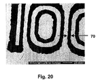
- the intricate design of the text having a resolution down to 60 microns, would prevent any counterfeiter from using scissors to simulate this security device.
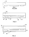
- a layer of patterned aluminum 22 on a PET web 20 is shown.
- This embodiment is not limited to the use of aluminum as a reflector material and other reflecting materials, for example another reflecting metal could be used instead of aluminum.
- the PET web forms the base of the security thread upon which the layers shown are deposited; however other materials, such as other plastics could be used in place of PET.
- the Aluminum patterned layer 22 is covered by a spacer layer 24 of MgF2 deposited over the patterned aluminum and web which forms windows 28 in regions over the web absent the deposited aluminum; a layer of absorber material 26, such as a thin layer of chromium, is deposited over the spacer layer 24.
- An optical interference structure is formed from the reflector/dielectric spacer/absorber ( R/D/Ab) stack over the remaining portions of the patterned metal, but not over the portions of the web where the Al has been removed; these portions were Al has been removed are referred to as window portions.
- the optical interference structure(s) 21 can be color filters that gives the patterned metal a particular appearance, or one that gives the patterned metal a color-shifting, "optically variable" appearance.
- the aluminum is patterned by printing an image or pattern onto the plastic web 20 using the "inhibiting oil” and then depositing a thin film of aluminum. Although the exact mechanism by which the oil prevents the sticking of the vacuum deposit to the substrate may not be entirely understood, the process nevertheless works. Various theories have been proposed to explain this phenomenon. One theory invokes the idea that the heat of condensation of the depositing material turns the oil into a gas and in effect ablates the metal away. Another explanation is that the oil simply prevents nucleation of the depositing material and hence the arriving material is scattered away.
- the Al-MgF 2 -Cr stacks each form a Fabry-Perot ("F-P”) absorber-spacer-reflector-type optically variable device (“OVD”), which are not formed over the window portions of the web because there is an absence of a Fabry-Perot structure in these areas.
- the plastic web can be clear, tinted, translucent, or opaque, and the materials chosen for the patterned metal layer and overlying thin films are merely exemplary.
- a protective layer is optionally applied, such as a thin layer of lacquer, not shown, or a thin (e.g. 0.5 mil) plastic film that is adhered to the OVD using laminating adhesives.
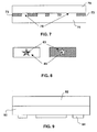
- Fig. 3 shows a layer structure, similar to that of Fig. 2 on a front side of a web 30.
- Patterned aluminum is deposited after using a roll-coater with inhibiting oil to apply a pattern of oil to prevent permanent deposition onto predetermined regions of the web 30 on a "front" side of a PET web.
- Layers 34 and 36 of MgF 2 and Cr are deposited over the front side to form optical interference structures over the Al; the Al serves as a reflector in the Fabry-Perot structure(s).
- Another optical structure 39 such as a reflective layer, an optically variable (OV) layer, a magnetic layer, either continuous or patterned, either sandwiched between layers of aluminum or as a single layer or fluorescent layer is formed on the "back" side of the web.
- OV optically variable
- a protective layer is optionally applied to both surfaces of the OVD.
- the optical structure may be opaque or semi-transmissive.
- a cover signature is present in the embodiment where a magnetic layer is sandwiched in between the reflective layer, as is described in United States Patent application number 2002/0160194A1 and WO 02090002(A2 ), in the name of the same inventor.
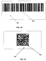
- a number in digital code or as in a bar code may be present, that is unseen by the naked eye, and may be fore validating the serial number on the bill or the denomination for example, $50.00.
- a magnetic bar code when hidden within the device, it exhibits the same reflective properties as aluminum but has a magnetic signature that can be read with appropriate magnetic detectors.
- the magnetic detection may be just the presence of a magnetic material as in a magnetic image such as a hidden bar code or a hidden logo, or may be a signal of digital or analog recorded information.
- the thickness of the magnetic layer is preferably between 0.1 and 1.0 microns in thickness.
- a thick layer for example having a thickness of 12 to 13 microns.
- this invention can provide a very thin layer that is detectable by providing a continuous layer of magnetic metal or metal that is detectable by magnets. Thinner layers are advantageous for use with security threads to be imbedded in or on currency so that a large stack of bills do not pile up at an angle when stacked. Furthermore, providing thinner layers ensures that overall thickness of the thread remains relatively thin, which is desired. Hence, the thickness of the magnetic layer should be less than 5 microns and preferably less.
- a single layer 42 of magnetic material may be deposited onto the plastic web 40, patterned by the oil imaging method, and then formed into a security thread, label or hot stamp image.
- the patterned magnetic layer 52 supported by a substrate 50 is sandwiched between two layers of aluminum 54 and 56 as is shown in Fig. 5 or is sandwiched between two layers of aluminum in a Fabry-Perot optical stack shown in detail in Fig. 6 wherein a substrate 60 has deposited thereon a patterned aluminum layer 62; upon the layer 62 is a Cr layer 63 a dielectric layer 64, and a magnetic layer 66 between two Al layers 65 and 67 upon the dielectric layer 64 .
- the magnetic layer 66 can be covered by a single layer of aluminum 67 and need not be sandwiched between two such layers.
- a cross-sectional view is shown wherein a plastic substrate 50 has deposited thereon a non-magnetic layer 54 of aluminum.
- a pattern of inhibiting oil is then applied to create a predetermined bar-code pattern of oil dependent upon the design upon the rollers that pick up the oil and coat the plastic web 50.
- the magnetic layer 52 is subsequently deposited and magnetic material only remains where no oil has been applied during the vacuum coating and cleaning process.
- a final layer of non-magnetic material 56 effectively sandwiches the magnetic layer 52 between the two non-magnetic layers.
- the depth of the vacuum deposition layer is considerably thinner than the thickness of the oil pattern; hence in relation to the oil thickness of about 10,000 Angstroms the small bumps of 1000 Angstroms or less for the vacuum deposited layer would be negligible.
- Patterning for multilayers could take place on unpatterned regions or even on previously patterned regions.
- Fig 6 is a more complex structure than that of Fig. 5 , however the method of manufacture is essentially the same, patterning and depositing subsequent layers.
- the combination of patterned thin film with color shifting ink including but not limited to inks containing pearlescent type pigments based on coated mica, SecureShift ® colors (registered to Flex Products), optically variable ink (OVI®, registered to SICPA), inks based on diffractive based pigments or liquid crystal color shifting inks can be present.
- the pigment may be formed of flat thin film optical structures or may be formed of diffractive flakes as described in US patent 6692830 and PCT patent application WO 03011980A1 .
- a patterned aluminum 73 is formed on a plastic film 70 such as polyester terephthalate (PET) and the color shifting ink 75 is coated over the patterned aluminum so that from the opposite side, one sees a color shift with viewing angle through the text or graphic images or appears as background around reflective text or graphics.
- PET polyester terephthalate
- Fig. 8 is an illustration showing that the background can be non-color shifting and foreground color shifting or vice versa.
- the color shifting ink is coated onto the surface opposite the patterned aluminum so that one views the security device from the patterned aluminum side.
- the color shifting ink shows through the openings of the patterned aluminum.
- the patterned aluminum can have an additional protective layer placed upon it, such as a scratch resistant lacquer or is laminated to a thin PET sheet typically having a thickness of 0.5 mil or less. Figs 9 and 10 exemplify these structures.
- a plastic web 90 has on an upper side thereof, an optically variable structure 92, for example in the form of optically variable ink, color shifting ink, optically variable pigment or a thin film Fabry-Perot cavity structure.
- an optically variable structure 92 for example in the form of optically variable ink, color shifting ink, optically variable pigment or a thin film Fabry-Perot cavity structure.
- a patterned layer of aluminum 94 is shown on a lower side of the web.
- a color shifting ink layer 106 is disposed upon a plastic substrate 100 and a patterned layer of aluminum 104 is deposited on the lower side of the substrate 100 having a protective lacquer coating 106 over it.
- the reflective layer is a layer of opaque aluminum, so that the window portions of the patterned layer appear reflective.
- the backside reflector does not typically form an OV structure with the front side MgF2-Cr layers because the intervening PET web is relatively thick for use as a spacer in a Fabry-Perot structure in the visible range of light.
- the window portions appear mirrored, while the front-side F-P structures provide an OVD as is shown in Fig. 3 .
- the optical structure on the backside of the web is an optical interference structure, such as a thin-film absorber layer on the PET web, a spacer layer over the absorber layer, and a reflective layer over the absorber layer, thus creating a second F-P structure in addition to the F-P structures on the frontside of the web as is shown in Fig. 11 .
- a reflective backside layer 112a is particularly desirable for security threads with OVDs because the mirror-like background provides a good visual reference to the color change of the frontside OVD.
- This reflective backside layer also serves as a layer in the optically variable structure defined by the two adjacent layers; a Cr layer 115a, a dielectric layer 111a.
- Fig. 11 also shows a plastic substrate 110 having a patterned aluminum layer 112, followed by a dielectric layer 111 having a layer of Cr 115 over top.
- a layer of color shifting ink may be applied to the backside of the web.
- the application of color shifting ink to the backside of the web enables an optically variable (OV) effect when the structure is viewed from either side.
- OV optically variable
- the OV effect of the color shifting ink is observed.
- the OV effect of the color-shifting ink structures formed with the patterned Al layer is observed, in addition to the OV effect of the color shifting ink.
- a PET web 120 is shown with patterned aluminum 112 on the front side and an optical structure on the backside.
- the optical structure is an organic layer 128 containing Anti-Stokes material in the form of powder.
- the Anti-Stokes layer fluoresces at a shorter wavelength when illuminated at a longer wavelength.
- Powdered Anti-Stokes material is available from STAR DUST TECHNOLOGIES.
- the particles are generally light-colored, such as a cream or a light tan color, and fluoresce in a color, such as blue, green, yellow, or orange when irradiated with near IR light, which is outside the visible range.
- a patterned optically variable foil comprising a patterned layer of aluminum 132, a dielectric layer 131, and a Cr layer 135 may be formed on one side of the PET and a printed layer of regular ink 136 is printed on the second side of the PET substrate 130.
- the printed ink 136 is either black in color or is a complimentary color to the normal (90 degree) color of the color shifting foil.
- the black or complimentary color shows through the windows of the patterned OVD or in the reversed image
- the black or complimentary color layer acts as a background for the color shifting patterned text.
- a green to blue color shifting foil would have a magenta printed ink on the second side of the PET; for example, green and magenta are complimentary colors.
- the contrast between the printed ink layer and the color shifting foil allows easy viewing in reflected light.
- a matching color could also be printed so that the reflected colors of the text only show up at other angles than the one at normal.
- the plastic web a plastic film 30 has an embossed surface coated with an aluminum layer 32 on the side opposite the patterned coating 34 so that the holographic imagery or diffractive imagery shows through the holes 36.
- Fig. 14 shows an OVD (optically variable device) formed on a web 140 wherein a reflective layer 142, such as an A1 layer is deposited, and an overlying spacer layer, such as an MgF2 layer 144, is patterned, with the oil-"inhibiting" technique.
- An absorber layer 146 such as a thin layer of Cr, is deposited over the underlying layers to form OVDs where the reflective, spacer, and absorber layers form an F-P structure.
- the embodiment shown in Figure 14 may have highly reflective regions proximate to the OVD structures that provide visual references when observing the OVD.
- more dielectric layer material can be deposited onto the patterned dielectric so that a color-shifting pattern is formed on top of a different color-shifting pattern, once the final absorber layer has been deposited.
- Fig. 15 shows an OVD formed on a web 150 with reflective and spacer layers 152 and 154 respectively formed on the web and an overlying patterned absorber layer 156.
- the absorber layer is patterned using the oil-ablation techniques.
- An OVD is formed where the absorber material remains.
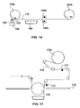
- Fig. 16 shows a simplified coating machine according to an embodiment of the invention.
- the coater includes an unwind roller 160a, a wind roller 160b, a printing head 162, an evaporation boat 164 and glow discharge elements 166a and 166b.
- the printing head 162 receives the "inhibiting oil” oil from the pick-up roller 168 and applies the oil to a PET web 170.
- the oil has the property that it does not readily evaporate in the vacuum of the roll coater, but readily evaporates when subjected to the heat of condensation of the evaporating material. In addition, the oil has the property that is does not spread on the surface of the plastic web i.e. there is little, if any, dot gain.
- the oil must stick to the substrate but not spread beyond the image area that is printed. Ideally, it should have an interaction with the plastic web but not spread. If it spreads beyond the image of the imprinting cylinder, the image will not be faithfully reproduced. If the graphic images are in pixel form, it is important that pixels are distinguishable from one another and do not have edges or portions that run into each other. Such an unwanted increase in pixel size is known as dot gain. For very thin layers of oil it likely does not make any difference whether it is wetting oil or non-wetting oil. However, it is preferable that oil not bead up._If the oil was thick and non-wetting, it would simply bead up and run off of the web and not maintain the printed image.
- the spreading of one material on another is determined by the respective surface energies, ⁇ A, ⁇ B and ⁇ AB, where ⁇ A is the surface tension (ie. surface energy) of the plastic web, ⁇ B is the surface tension of the oil and ⁇ AB is the interfacial surface tension.
- ⁇ A is the surface tension (ie. surface energy) of the plastic web
- ⁇ B is the surface tension of the oil
- ⁇ AB is the interfacial surface tension.
- S L/S ⁇ A - ⁇ B - yAB, where S L/S is the spreading coefficient. If S L/S is positive, spreading will occur.
- ⁇ A is larger than the sum of ⁇ B and ⁇ AB which means ( ⁇ B plus ⁇ AB) has a lower surface energy than ⁇ A. Thus, to minimize energy, spreading will occur.
- S L/S should be negative so that spreading of the oil on the plastic substrate does not occur.
- spreading would be detrimental since the dot gain would reduce the resolution from the original print image on the patterned imaging roller.
- the oil also has a low vapor pressure so that it does not evaporate after printing the image onto the web.
- FOMBLIN or Krytox oils meet the spreading criteria; however, other low vapor pressure oils may be used depending on the substrate being used.
- the web is advanced to the evaporation boat, which deposits Al or other material on the surface of the web.
- Process conditions are controlled so that the heat of condensation of the Al vaporizes the oil where it underlies the Al, removing the Al from the regions that previously had oil.
- the oil prevents nucleation of the depositing aluminum, ie. the aluminum does not stick and re-evaporates into the chamber.
- oil residue products of oil breakdown and/or residual oil may be present on some portions of the web, including the backside of the web after vacuum deposition. Such residue can degrade the optical performance of OVDs subsequently formed on the web and prevents acceptable adhesion of subsequent then film layers.
- a glow discharge cleaning technique was used to successfully remove oil residue.
- Several types of glow discharge cleaning techniques were evaluated, as well as other cleaning techniques.
- a glow discharge cleaning technique using argon gas was tried, but did not adequately clean the residue of the oil used in the patterning process.
- IR heaters were used before coating, but oil transfer still occurred, presumably because oil transfer between layers of the web occurred.
- oil residue on the frontside of the web will be transferred to the backside of the web on the wind roll.
- frontside cleaning of residue may be sufficient.
- the coater may be omitted, such as tensioning rollers and chamber dividers.
- the web may be held against a drum during the Al deposition/patterning.
- Fig. 17 shows a simplified depositing apparatus for cleaning a patterned web.
- the patterned web 170 comes off the unwind roller 170b and along a series of tension rollers.
- the backside of the web is cleaned at a first station with a first glow bar 171, shown as being unshrouded.
- the frontside of the web is cleaned at a second station 172 further along the web with a glowbar that is shrouded.
- the shroud is optionally omitted if the glow discharge does not affect other system components.
- cleaning the backside of the web might not be necessary in all embodiments. Oxygen was provided to the glowbar shroud, but could be provided at other locations of the chamber.
- a chamber divider 179 keeps material from the OV source(s) from depositing on the tension rollers and other system components.
- the web is tensioned against a coating drum 178 during deposition of the OV layers.
- a glow discharge using O 2 as the precursor was found to work well to clean the web of oil residue. Other precursors may be preferred for other oils or liquids, or even for this type of oil residue.
- a web of PET about 8.5 inches wide was transported through a glow discharge cleaning stage at a speed of 0.5 meters/second.
- the total current to the backside glowbar and the frontside glowbar was 100 mA and the glowbars were operated at 2,200 Volts.
- Pure O 2 was provided to the shroud of the frontside glowbar to create a chamber pressure of 5 x 10 -3 Torr to remove the residual oil from both sides of the patterned web.
- An OVD that was formed on the patterned web after cleaning in this fashion showed good optical characteristics, suitable for use in commercial applications.
- the invention is generally directed toward methods and apparatus for manufacturing imaged foils, as well as security articles including optically variable foils and security labels.
- an optically variable foil is produced using an all vacuum in-line process.
- a substrate consisting of 0.25 to 5 mil PET, preferably 0.5-1.0 mil (1 mil 25.4 microns) is first patterned on the web, width 2"-60" or more, with a positive or negative image with perfluorinated polyether as described in US publication "Proceedings of the Fourteenth International Conference on Vacuum Web Coating, October 25-27,2000 by Aerre Machine.
- a printing station similar to that described in US 4,749,591 was used and is incorporated herein as a reference. However, the printing method is not necessarily limited to that described in US 4,749,591 .
- other printing techniques may be used include ink-jet printing, flexographic printing, gravure printing or lithographic printing, or even dot matrix printing.
- a security thread with an optically variable feature may be combined with a hidden magnetic bar code in either one dimension, as in a standard bar code, or in a two dimensions, as in a 2D bar code format.
- the magnetic layer is hidden between other layers of the thin film design, as for example behind a reflective layer or sandwiched between two highly reflective aluminum layers as shown in Figs. 18 and 19 .
- the printing station should be situated on the cooled drum immediately before the deposition of the first layer, typically aluminum, but may be any material with a heat of condensation sufficient to vaporize the imaged oil.
- Other substrates such as polyimide, polyhexadiene, polypropylene, polyethylene, polystyrene, polycarbonate triacetate, biacetate, and polynathphanate (PEN) may be used instead of the polyethylene terephthalate (PET).
- PET polyethylene terephthalate
- patterning oils based on the fundamental surface energies encountered and required low vapor pressures as described above would be used.
- Depositing the first layer that is to be imaged is the next process step to be performed.
- either the reflector layer or the absorber layer may be imaged.
- any layer may be imaged as long as the oil patterning process produces a discreet oil image.
- the imaging may occur in the dielectric layer by placing the oil image on the prior-deposited layer.
- the reflector layer or the absorber layer may be the layer upon which the oil image is placed.
- Deposition of a metal layer onto the patterned oil results in explosive evolution of liquid oil into gas, causing the depositing layer to be ablated away. There may be some residual oil (several monolayers of oil) remaining in the patterned area which must be removed in order to this imaged oil from transferring further down the web which would in turn cause ghosting (another image pattern) of any subsequent deposition layers.
- the aluminum layer or the chromium layer is imaged and then the rest of the design is added to complete a Fabry-Perot structure, i.e. Al (opaque, patterned)/MgF 2 1 QW @ 400nm to 8QW@ 700nm/Cr 30%T.
- the low index MgF 2 layer may be substituted by any dielectric material that is highly transmissive in the visible. High index dielectric materials will result in an optically variable foil that is less shifting in color than one that has a large optical shift where a low index dielectric material is used.
- a partially aluminum layer that has a thickness below the opaque point, for example, thickness in the range 200-800 nm, will give a color shifting film that is partially transparent so that information may be read through the optical stack from the paper, or that is printed on the PET. All color shifts move from long to shorter wavelengths, i.e. from red-to-blue.
- an oxygen glow situated right after the deposition source on the cooled drum is used. Glows may also be used on the backside of the web before and after the deposition area. In this instance, the 02 glow will remove any oil from the backside of the web that might have transferred during the "inking process” or flash over during the deposition process that could end up on the back side during wind-up.
- the oxygen glow is run at 2,200 volts at 100 ma for a 12" wide glow system. Residual oil may be detected on the final coated web by noting the variation in color, for example blotches or ghost like images of the original images.
- a graphic image can be made by processing a scanned image using a FloydSteinburg technique as found in the software program COREL DRAWTM. This program converts the image into square pixels, which have good black (image) and white (no image) contrast. After coating, the web is slit into ribbons between 1 and 5 mm wide wherein the text is generally situated in the center of the ribbon.
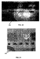
- Fig. 21 show the optically variable thread of this invention windowed into a bank note and Fig. 22 shows the text symbols when viewed in transmission.
- the device may function as a security stick-on label by applying adhesive 232 to one side of the PET and laminating to a release layer 234 supported by paper carrier 236 and die cutting the label 230 as is shown in Fig. 23 .
- the adhesive can be a solvent based or a water-based adhesive.
- a suitable adhesive is an acrylic adhesive, among many others.
- the product could be made into a hot-stamp security product by inserting a release layer between the carrier web and the vacuum deposited layer.
Applications Claiming Priority (2)
| Application Number | Priority Date | Filing Date | Title |
|---|---|---|---|
| US48752703P | 2003-07-14 | 2003-07-14 | |
| EP04016542.5A EP1498545B1 (de) | 2003-07-14 | 2004-07-14 | Sicherheitsfaden enthaltend eine optisch variable struktur |
Related Parent Applications (3)
| Application Number | Title | Priority Date | Filing Date |
|---|---|---|---|
| EP04016542.5 Division | 2004-07-14 | ||
| EP04016542.5A Division EP1498545B1 (de) | 2003-07-14 | 2004-07-14 | Sicherheitsfaden enthaltend eine optisch variable struktur |
| EP04016542.5A Division-Into EP1498545B1 (de) | 2003-07-14 | 2004-07-14 | Sicherheitsfaden enthaltend eine optisch variable struktur |
Publications (2)
| Publication Number | Publication Date |
|---|---|
| EP2287399A1 true EP2287399A1 (de) | 2011-02-23 |
| EP2287399B1 EP2287399B1 (de) | 2021-06-16 |
Family
ID=33477004
Family Applications (2)
| Application Number | Title | Priority Date | Filing Date |
|---|---|---|---|
| EP04016542.5A Revoked EP1498545B1 (de) | 2003-07-14 | 2004-07-14 | Sicherheitsfaden enthaltend eine optisch variable struktur |
| EP10183278.0A Active EP2287399B1 (de) | 2003-07-14 | 2004-07-14 | Sicherheitsfaden enthaltend eine optisch variable Struktur |
Family Applications Before (1)
| Application Number | Title | Priority Date | Filing Date |
|---|---|---|---|
| EP04016542.5A Revoked EP1498545B1 (de) | 2003-07-14 | 2004-07-14 | Sicherheitsfaden enthaltend eine optisch variable struktur |
Country Status (7)
| Country | Link |
|---|---|
| US (5) | US20050042449A1 (de) |
| EP (2) | EP1498545B1 (de) |
| JP (1) | JP4964408B2 (de) |
| KR (3) | KR101110767B1 (de) |
| CN (4) | CN101824776B (de) |
| HK (2) | HK1147975A1 (de) |
| TW (1) | TWI334382B (de) |
Cited By (2)
| Publication number | Priority date | Publication date | Assignee | Title |
|---|---|---|---|---|
| US10482361B2 (en) | 2015-07-05 | 2019-11-19 | Thewhollysee Ltd. | Optical identification and characterization system and tags |
| EP3129237B1 (de) | 2014-04-08 | 2020-06-10 | Giesecke+Devrient Currency Technology GmbH | Verfahren zur herstellung eines sicherheitselements |
Families Citing this family (88)
| Publication number | Priority date | Publication date | Assignee | Title |
|---|---|---|---|---|
| US7667895B2 (en) | 1999-07-08 | 2010-02-23 | Jds Uniphase Corporation | Patterned structures with optically variable effects |
| US7517578B2 (en) | 2002-07-15 | 2009-04-14 | Jds Uniphase Corporation | Method and apparatus for orienting magnetic flakes |
| US7047883B2 (en) | 2002-07-15 | 2006-05-23 | Jds Uniphase Corporation | Method and apparatus for orienting magnetic flakes |
| US7604855B2 (en) | 2002-07-15 | 2009-10-20 | Jds Uniphase Corporation | Kinematic images formed by orienting alignable flakes |
| US6761959B1 (en) | 1999-07-08 | 2004-07-13 | Flex Products, Inc. | Diffractive surfaces with color shifting backgrounds |
| CA2397806C (en) | 2000-01-21 | 2009-05-05 | Flex Products, Inc. | Optically variable security devices |
| US11768321B2 (en) | 2000-01-21 | 2023-09-26 | Viavi Solutions Inc. | Optically variable security devices |
| US6902807B1 (en) | 2002-09-13 | 2005-06-07 | Flex Products, Inc. | Alignable diffractive pigment flakes |
| US11230127B2 (en) | 2002-07-15 | 2022-01-25 | Viavi Solutions Inc. | Method and apparatus for orienting magnetic flakes |
| US7934451B2 (en) | 2002-07-15 | 2011-05-03 | Jds Uniphase Corporation | Apparatus for orienting magnetic flakes |
| US7645510B2 (en) | 2002-09-13 | 2010-01-12 | Jds Uniphase Corporation | Provision of frames or borders around opaque flakes for covert security applications |
| US8025952B2 (en) | 2002-09-13 | 2011-09-27 | Jds Uniphase Corporation | Printed magnetic ink overt security image |
| US9458324B2 (en) * | 2002-09-13 | 2016-10-04 | Viava Solutions Inc. | Flakes with undulate borders and method of forming thereof |
| US9164575B2 (en) | 2002-09-13 | 2015-10-20 | Jds Uniphase Corporation | Provision of frames or borders around pigment flakes for covert security applications |
| US7241489B2 (en) | 2002-09-13 | 2007-07-10 | Jds Uniphase Corporation | Opaque flake for covert security applications |
| US7674501B2 (en) | 2002-09-13 | 2010-03-09 | Jds Uniphase Corporation | Two-step method of coating an article for security printing by application of electric or magnetic field |
| US7258915B2 (en) | 2003-08-14 | 2007-08-21 | Jds Uniphase Corporation | Flake for covert security applications |
| AT504587A1 (de) * | 2004-02-16 | 2008-06-15 | Hueck Folien Gmbh | Fälschungssicheres sicherheitsmerkmal mit farbkippeffekt |
| US8354069B2 (en) | 2005-03-08 | 2013-01-15 | Authentix, Inc. | Plug flow system for identification and authentication of markers |
| EP1868725B1 (de) * | 2005-03-08 | 2012-01-18 | Authentix, Inc. | Verwendung einer mikrofluidischen vorrichtung zur identifikation, quantifizierung und authentifizierung latenter marker |
| CA2541568C (en) | 2005-04-06 | 2014-05-13 | Jds Uniphase Corporation | Dynamic appearance-changing optical devices (dacod) printed in a shaped magnetic field including printable fresnel structures |
| CN1854944B (zh) * | 2005-04-20 | 2011-02-09 | Jds尤尼弗思公司 | 具有光学可变效果的图案化结构 |
| DE102005031448A1 (de) * | 2005-07-04 | 2007-01-11 | Polyic Gmbh & Co. Kg | Aktivierbare optische Schicht |
| AT502160B1 (de) * | 2005-07-12 | 2013-07-15 | Hueck Folien Gmbh | Sicherheitsfolie zur sicherung von dokumenten |
| ITMI20051944A1 (it) * | 2005-10-14 | 2007-04-15 | Fabriano Securities Srl | Elemento di sicurezza per banconote o documenti rappresentanti un valore |
| CA2564764C (en) | 2005-10-25 | 2014-05-13 | Jds Uniphase Corporation | Patterned optical structures with enhanced security feature |
| AT503714A2 (de) * | 2005-12-13 | 2007-12-15 | Hueck Folien Ges Mbh | Sicherheitselemente und sicherheitsmerkmale mit metallisch erscheinenden farbeffekten |
| CA2570965A1 (en) | 2005-12-15 | 2007-06-15 | Jds Uniphase Corporation | Security device with metameric features using diffractive pigment flakes |
| US10343436B2 (en) | 2006-02-27 | 2019-07-09 | Viavi Solutions Inc. | Security device formed by printing with special effect inks |
| US20070281177A1 (en) * | 2006-05-31 | 2007-12-06 | Cabot Corporation | Colored Reflective Features And Inks And Processes For Making Them |
| TWI437059B (zh) | 2006-07-12 | 2014-05-11 | Jds Uniphase Corp | 壓印一經硬化及場配向之特效薄片之塗層及藉此形成之圖像 |
| US7719752B2 (en) | 2007-05-11 | 2010-05-18 | Qualcomm Mems Technologies, Inc. | MEMS structures, methods of fabricating MEMS components on separate substrates and assembly of same |
| DE102007048280A1 (de) * | 2007-10-08 | 2009-04-09 | Tesa Ag | Klebeband für den fliegenden Rollenwechsel |
| EP2067825A3 (de) * | 2007-12-05 | 2010-09-15 | JDS Uniphase Corporation | Verstärkter Glitter |
| JP2009193069A (ja) | 2008-02-13 | 2009-08-27 | Jds Uniphase Corp | 光学的な特殊効果フレークを含むレーザ印刷用の媒体 |
| BRPI0906096A2 (pt) * | 2008-03-05 | 2015-06-30 | 3M Innovative Properties Co | Fibras poliméricas, corpo óptico, método para a fabricação de fibra polimérica, artigo seguro e método de verificação de um artigo |
| DE102008013073B4 (de) | 2008-03-06 | 2011-02-03 | Leonhard Kurz Stiftung & Co. Kg | Verfahren zur Herstellung eines Folienelements und Folienelement |
| US8023191B2 (en) * | 2008-05-07 | 2011-09-20 | Qualcomm Mems Technologies, Inc. | Printable static interferometric images |
| KR100976245B1 (ko) | 2008-07-25 | 2010-08-18 | 엘지엔시스(주) | 센서 레벨링 방법 및 장치, 그리고 그를 이용한 자동화기기 |
| EP2159071B2 (de) * | 2008-08-25 | 2022-01-12 | Hueck Folien Ges.m.b.H. | Sicherheitselement, das ohne Hilfsmittel verifiziert werden kann |
| DE102008049631A1 (de) * | 2008-09-30 | 2010-04-01 | Giesecke & Devrient Gmbh | Karte mit eingebettetem Sicherheitsmerkmal |
| CA2656506A1 (en) * | 2009-02-27 | 2010-08-27 | Bank Of Canada | Security device |
| US8261988B2 (en) * | 2009-11-30 | 2012-09-11 | Xerox Corporation | Phase locked IR encoding for peened 2D barcodes |
| AR080431A1 (es) | 2010-03-03 | 2012-04-11 | Sicpa Holding Sa | Hilo o tira de seguridad que comprende particulas magneticas orientadas en tinta y procedimiento y medio para producir el mismo |
| CN101863193B (zh) * | 2010-03-16 | 2012-11-14 | 中国人民银行印制科学技术研究所 | 印刷防伪图纹及其制作方法以及具有其的防伪制品 |
| EP2585862B8 (de) * | 2010-06-25 | 2017-10-11 | Andrew Richard Parker | Strukturen für optische effekte |
| US20120018994A1 (en) * | 2010-07-23 | 2012-01-26 | Scott Thomas Stalker | Lottery ticket with holographic appearance |
| US8815337B2 (en) * | 2011-04-21 | 2014-08-26 | Sigma Laboratories Of Arizona, Llc | Methods for fabrication of polymer-based optically variable devices |
| ITTO20110537A1 (it) * | 2011-06-20 | 2012-12-21 | Nicanti Srl | Film di sicurezza comprendente un codice leggibile a radiofrequenza |
| FR2976954B1 (fr) * | 2011-06-23 | 2013-07-12 | Arjowiggins Security | Fil de securite |
| EP2538247B1 (de) | 2011-06-23 | 2018-04-11 | Viavi Solutions Inc. | Mehrfarbige Farbkipp-Sicherheitselemente |
| AU2011100778B4 (en) * | 2011-06-29 | 2011-10-13 | Ccl Secure Pty Ltd | Improvements in security devices incorporating colour shifting inks |
| GB2493369B (en) | 2011-08-02 | 2013-09-25 | Rue De Int Ltd | Improvements in security devices |
| RU2016144474A (ru) * | 2011-09-26 | 2018-12-18 | Крейн Секьюрити Текнолоджис, Инк. | Способ изготовления композитной ленты и защитные средства, выполненные из композитной ленты |
| PL2578414T3 (pl) | 2011-10-04 | 2014-05-30 | Hueck Folien Gmbh | Element zabezpieczający z efektem zmiany barw przy przechylaniu, sposób jego wytwarzania i jego zastosowanie |
| DE102011119598A1 (de) | 2011-11-29 | 2013-05-29 | Ovd Kinegram Ag | Optisch variables Element |
| KR101857160B1 (ko) * | 2011-12-16 | 2018-05-15 | 한국전자통신연구원 | 반도체 레이저 및 그의 제조방법 |
| IN2014MN01816A (de) | 2012-01-12 | 2015-06-12 | Jds Uniphase Corp | |
| DE102012003519A1 (de) * | 2012-02-24 | 2013-08-29 | Polysecure Gmbh | Werkstück mit Markierung |
| CN104641408A (zh) * | 2012-04-05 | 2015-05-20 | 阿塞里克股份有限公司 | 包括标识的家用器具以及标识涂覆方法 |
| FR2992255B1 (fr) | 2012-06-22 | 2015-09-04 | Arjowiggins Security | Element de securite et document securise. |
| EP2882597B1 (de) | 2012-08-01 | 2017-02-01 | Sicpa Holding SA | Optisch variable sicherheitsfäden und -streifen |
| EP2890847A4 (de) | 2012-08-29 | 2016-04-13 | Sicpa Holding Sa | Optisch variable sicherheitsfäden und -streifen |
| HUE056543T2 (hu) * | 2013-03-15 | 2022-02-28 | Crown Packaging Technology Inc | Mátrix vonalkódok dobozkomponenseken |
| AU2014261618B2 (en) | 2013-05-02 | 2017-05-25 | Sicpa Holding Sa | Processes for producing security threads or stripes |
| FR3005436B1 (fr) | 2013-05-13 | 2016-01-01 | Fasver | Procede et dispositif de protection securitaire d'un document officiel et document officiel ainsi protege |
| JP6655278B2 (ja) * | 2013-06-08 | 2020-02-26 | トヨタ モーター エンジニアリング アンド マニュファクチャリング ノース アメリカ,インコーポレイティド | 高クロマ全方向構造色多層構造 |
| CN103473589B (zh) * | 2013-09-10 | 2016-09-14 | 江苏多维科技有限公司 | 一种磁条形码芯片及其读取方法 |
| WO2015085505A1 (en) | 2013-12-11 | 2015-06-18 | Sicpa Holding Sa | Optically variable security threads and stripes |
| CN105980162B (zh) | 2014-02-13 | 2017-09-22 | 锡克拜控股有限公司 | 安全线和条 |
| PL2965920T3 (pl) | 2014-07-09 | 2018-03-30 | Sicpa Holding Sa | Optycznie zmienne magnetyczne nitki zabezpieczające i paski |
| CN104266979B (zh) * | 2014-10-17 | 2017-10-03 | 中国人民银行印制科学技术研究所 | 一种用于识别含有细菌视紫红质或其变体的标记的元件、使用该元件的标记物及其鉴别方法 |
| AT516688A1 (de) | 2014-12-15 | 2016-07-15 | Hueck Folien Gmbh | Sicherheitselement mit Farbkippeffekt und fluoreszierenden Merkmalen, Verfahren zu dessen Herstellung und dessen Verwendung |
| CN104616391B (zh) * | 2015-02-12 | 2017-06-06 | 西安印艺苑实业有限公司 | 票据验证方法和装置 |
| DE102015003665A1 (de) * | 2015-03-20 | 2016-09-22 | Giesecke & Devrient Gmbh | Sicherheitselement |
| US10036125B2 (en) | 2015-05-11 | 2018-07-31 | Nanotech Security Corp. | Security device |
| US20180170093A1 (en) * | 2015-06-30 | 2018-06-21 | Spectral Devices Inc. | Flexible pixelated fabry-perot filter |
| US9878574B2 (en) | 2015-08-11 | 2018-01-30 | YPB Group, Ltd. | Security foil and method |
| KR102100669B1 (ko) * | 2016-09-27 | 2020-05-27 | (주)엘지하우시스 | 차량용 내장재의 제조방법 및 차량용 내장재 |
| US10899930B2 (en) * | 2017-11-21 | 2021-01-26 | Viavi Solutions Inc. | Asymmetric pigment |
| CN108681765A (zh) * | 2018-02-15 | 2018-10-19 | 海南亚元防伪技术研究所(普通合伙) | 超限窄缝防伪方法及产品 |
| CN109243326A (zh) * | 2018-10-24 | 2019-01-18 | 苏州益邦电子材料有限公司 | 自保护式铭牌 |
| CN113272087B (zh) | 2019-01-29 | 2024-04-19 | 巴斯夫欧洲公司 | 安全元件 |
| CN111845148B (zh) * | 2019-04-24 | 2022-04-05 | 中钞特种防伪科技有限公司 | 光学防伪元件及其制作方法 |
| AT522774B1 (de) * | 2019-09-11 | 2021-01-15 | Hueck Folien Gmbh | Sicherheitselement für Wertpapiere oder Sicherheitspapiere mit einer Trägerfolie |
| TWI737042B (zh) * | 2019-11-21 | 2021-08-21 | 李錦峰 | 防偽標籤 |
| KR102432996B1 (ko) * | 2020-05-13 | 2022-08-17 | 엔비에스티(주) | 콜레스테릭 액정 표시층을 포함하는 위변조 방지수단 |
| CN115341409A (zh) * | 2022-08-26 | 2022-11-15 | 湖南和锐镭射科技有限公司 | 一种嵌入式防伪高光亮纸制作方法及嵌入式防伪高光亮纸 |
Citations (31)
| Publication number | Priority date | Publication date | Assignee | Title |
|---|---|---|---|---|
| DE2205428A1 (de) | 1971-03-23 | 1972-11-02 | Landis & Gyr A.G., Zug (Schweiz) | Wertzeichen |
| US4022928A (en) | 1975-05-22 | 1977-05-10 | Piwcyzk Bernhard P | Vacuum deposition methods and masking structure |
| US4242378A (en) * | 1979-03-29 | 1980-12-30 | Reiko Co., Ltd. | Method of making a decorated film with a metal layer in the form of a given pattern |
| GB2119312A (en) | 1982-04-27 | 1983-11-16 | Bank Of England The Governor A | Sheet having a reflective anti-counterfeiting device |
| WO1987000208A1 (en) | 1985-07-03 | 1987-01-15 | Metalvuoto Films S.P.A. | Device for making metallized plastic films with clearly defined non-metallized areas |
| US4652015A (en) | 1985-12-05 | 1987-03-24 | Crane Company | Security paper for currency and banknotes |
| US4705356A (en) | 1984-07-13 | 1987-11-10 | Optical Coating Laboratory, Inc. | Thin film optical variable article having substantial color shift with angle and method |
| US4838648A (en) | 1988-05-03 | 1989-06-13 | Optical Coating Laboratory, Inc. | Thin film structure having magnetic and color shifting properties |
| EP0435029A2 (de) | 1989-12-22 | 1991-07-03 | GAO Gesellschaft für Automation und Organisation mbH | Datenträger mit einem Flüssigkristall-Sicherheitselement |
| US5135812A (en) | 1979-12-28 | 1992-08-04 | Flex Products, Inc. | Optically variable thin film flake and collection of the same |
| US5214530A (en) | 1990-08-16 | 1993-05-25 | Flex Products, Inc. | Optically variable interference device with peak suppression and method |
| US5278590A (en) | 1989-04-26 | 1994-01-11 | Flex Products, Inc. | Transparent optically variable device |
| EP0624688A1 (de) | 1993-05-12 | 1994-11-17 | Arjo Wiggins S.A. | Sicherheitsblatt mit geschützten Sicherheitselementen, und Verfahren zu seiner Herstellung |
| GB2347646A (en) | 1999-03-12 | 2000-09-13 | Rue De Int Ltd | Security element comprising thermochromic coating and optically variable device eg hologram |
| US6157489A (en) | 1998-11-24 | 2000-12-05 | Flex Products, Inc. | Color shifting thin film pigments |
| DE19928060A1 (de) * | 1999-06-15 | 2000-12-21 | Whd Elektron Prueftech Gmbh | Optisch variables Sicherheitsmerkmal und Verfahren zu seiner Herstellung |
| WO2001007268A1 (en) * | 1999-07-23 | 2001-02-01 | De La Rue International Limited | Security device |
| US6241858B1 (en) | 1999-09-03 | 2001-06-05 | Flex Products, Inc. | Methods and apparatus for producing enhanced interference pigments |
| WO2001053113A1 (en) * | 2000-01-21 | 2001-07-26 | Flex Products, Inc. | Optically variable security devices |
| US20020160194A1 (en) | 2001-04-27 | 2002-10-31 | Flex Products, Inc. | Multi-layered magnetic pigments and foils |
| US6474695B1 (en) | 1988-03-04 | 2002-11-05 | Gao Gessellschaft Fur Automation Und Organisation Gmbh | Security element in the form of a thread or be embedded in security and methods of producing it |
| WO2002090002A2 (en) | 2001-05-07 | 2002-11-14 | Flex Products, Inc. | Methods for producing imaged coated articles by using magnetic pigments |
| EP1258334A2 (de) | 2001-05-10 | 2002-11-20 | De La Rue International Limited | Verfahren zur Herstellung eines Sicherheitsgegenstands |
| DE10122836A1 (de) | 2001-05-11 | 2002-11-28 | November Ag Molekulare Medizin | Faser, Faden und Verfahren zur Markierung und Identifizierung |
| WO2002101147A1 (fr) | 2001-06-08 | 2002-12-19 | Rexor | Fil de securite ou film de transfert pour marquage a chaud pour billets de banque, documents ou autres articles a securiser |
| WO2002103624A1 (en) | 2001-06-15 | 2002-12-27 | Crane & Co., Inc. | Security device having multiple security detection features |
| WO2003011980A1 (en) | 2001-07-31 | 2003-02-13 | Flex Products, Inc. | Diffractive pigment flakes and compositions |
| US20030072931A1 (en) * | 2001-05-24 | 2003-04-17 | 3M Innovative Properties Company | Low Tg multilayer optical films |
| US6569529B1 (en) | 2000-10-10 | 2003-05-27 | Flex Product, Inc. | Titanium-containing interference pigments and foils with color shifting properties |
| US6699313B2 (en) | 2000-07-27 | 2004-03-02 | Flex Products, Inc. | Composite reflective flake based pigments |
| US6706412B2 (en) | 1994-11-04 | 2004-03-16 | Sigma Laboratories Of Arizona | Barrier film for limiting transmission of oxygen and moisture therethrough |
Family Cites Families (69)
| Publication number | Priority date | Publication date | Assignee | Title |
|---|---|---|---|---|
| US3338730A (en) | 1964-02-18 | 1967-08-29 | Little Inc A | Method of treating reflective surfaces to make them multihued and resulting product |
| US3662156A (en) * | 1968-09-16 | 1972-05-09 | Strategic Automated Systems In | Laminated record card comprising internal layer of high tensile strands |
| US3858977A (en) | 1972-01-18 | 1975-01-07 | Canadian Patents Dev | Optical interference authenticating means |
| US5766738A (en) * | 1979-12-28 | 1998-06-16 | Flex Products, Inc. | Paired optically variable article with paired optically variable structures and ink, paint and foil incorporating the same and method |
| US4816322A (en) * | 1981-11-02 | 1989-03-28 | Dennison Manufacturing Company | Anticounterfeit metallized labels |
| US4511616A (en) * | 1983-02-14 | 1985-04-16 | Dennison Mfg. Company | Anticounterfeit magnetic metallized labels |
| US4837061A (en) * | 1987-08-10 | 1989-06-06 | Alcan International Limited | Tamper-evident structures |
| US5876068A (en) | 1988-03-04 | 1999-03-02 | Gao Gessellschaft Fur Automation Und Organisation Gmbh | Security element in the form of a thread or strip to be embedded in security documents and methods of producing it |
| DE3932505C2 (de) * | 1989-09-28 | 2001-03-15 | Gao Ges Automation Org | Datenträger mit einem optisch variablen Element |
| GB8924111D0 (en) * | 1989-10-26 | 1989-12-13 | Amblehurst Ltd | Optical device |
| DE4100643C1 (de) | 1991-01-11 | 1991-10-31 | Leybold Ag, 6450 Hanau, De | |
| EP0556449B1 (de) * | 1992-02-21 | 1997-03-26 | Hashimoto Forming Industry Co., Ltd. | Lackierung mit magnetisch hergestelltem Muster und lackiertes Produkt mit magnetisch hergestelltem Muster |
| GB9218216D0 (en) * | 1992-08-27 | 1992-10-14 | Payne P P Ltd | Improvements in or relating to tapes |
| US5549953A (en) * | 1993-04-29 | 1996-08-27 | National Research Council Of Canada | Optical recording media having optically-variable security properties |
| DE4334847A1 (de) * | 1993-10-13 | 1995-04-20 | Kurz Leonhard Fa | Wertdokument mit Fenster |
| TW265421B (de) * | 1993-11-23 | 1995-12-11 | Commw Scient Ind Res Org | |
| ES2108814T3 (es) * | 1993-12-10 | 1998-01-01 | Agfa Gevaert Nv | Documento de seguridad con un soporte transparente o translucido y que contiene pigmentos de interferencia. |
| US5464710A (en) * | 1993-12-10 | 1995-11-07 | Deposition Technologies, Inc. | Enhancement of optically variable images |
| US5424119A (en) * | 1994-02-04 | 1995-06-13 | Flex Products, Inc. | Polymeric sheet having oriented multilayer interference thin film flakes therein, product using the same and method |
| DE4410431A1 (de) | 1994-03-25 | 1995-09-28 | Giesecke & Devrient Gmbh | Vor unerlaubter Reproduktion mit einem Kopiergerät geschützte Ausweiskarte |
| US5616911A (en) * | 1995-05-24 | 1997-04-01 | Eastman Kodak Company | Read-only magnetic security pattern |
| EP0756945A1 (de) | 1995-07-31 | 1997-02-05 | National Bank Of Belgium | Farbkopierschutz für Sicherheitsdokumente |
| DE19548528A1 (de) * | 1995-12-22 | 1997-06-26 | Giesecke & Devrient Gmbh | Sicherheitsdokument mit einem Sicherheitselement und Verfahren zu dessen Herstellung |
| US5891552A (en) * | 1996-01-04 | 1999-04-06 | Mobil Oil Corporation | Printed plastic films and method of thermal transfer printing |
| GB9612496D0 (en) * | 1996-06-14 | 1996-08-14 | De La Rue Thomas & Co Ltd | Security device |
| AUPO260296A0 (en) * | 1996-09-26 | 1996-10-24 | Reserve Bank Of Australia | Banknotes incorporating security devices |
| JPH10222074A (ja) * | 1997-02-10 | 1998-08-21 | Toppan Printing Co Ltd | 偽造防止用サインパネル |
| GB2323814B (en) * | 1997-04-03 | 1999-06-02 | Portals Ltd | Security element for security paper |
| GB9709263D0 (en) * | 1997-05-07 | 1997-06-25 | Astor Universal Limited | Laminate structure |
| GB2325883B (en) | 1997-06-03 | 2000-01-12 | Portals Ltd | A security article,a method and manufacture of the security article,a method of verifying authenticity of the security article and security paper |
| JP3329234B2 (ja) * | 1997-06-20 | 2002-09-30 | 凸版印刷株式会社 | 偽造防止用フィルム及び偽造防止用転写箔 |
| JPH1158581A (ja) * | 1997-08-25 | 1999-03-02 | Toppan Printing Co Ltd | 偽造防止用積層材料 |
| IT1296098B1 (it) * | 1997-11-11 | 1999-06-09 | Mantegazza Walter | Filo di sicurezza con informazioni ottiche e magnetiche inseribile in documenti in genere |
| CN1257053C (zh) * | 1997-11-18 | 2006-05-24 | 松下电器产业株式会社 | 层叠体和电容器 |
| UA52804C2 (uk) * | 1997-12-02 | 2003-01-15 | Текнікал Графікс Сек'Юріті Продактс, Ллс | Магнітний/металевий захисний пристрій (варіанти), спосіб його виготовлення (варіанти), спосіб встановлення його автентичності і металевий захисний пристрій |
| AUPP134298A0 (en) * | 1998-01-15 | 1998-02-05 | Securency Pty Ltd | Security document having visually concealed security indicia |
| DE69901886T3 (de) | 1998-03-10 | 2008-01-24 | De La Rue International Ltd., Basingstoke | Verfahren zur herstellung eines sicherheitsgegenstands |
| EP0967091A1 (de) * | 1998-06-26 | 1999-12-29 | Alusuisse Technology & Management AG | Gegenstand mit optischem Effekt |
| US6105589A (en) * | 1999-01-11 | 2000-08-22 | Vane; Ronald A. | Oxidative cleaning method and apparatus for electron microscopes using an air plasma as an oxygen radical source |
| JP3701138B2 (ja) * | 1999-04-23 | 2005-09-28 | 松下電器産業株式会社 | 電子部品の製造方法 |
| JP4507353B2 (ja) * | 1999-06-03 | 2010-07-21 | パナソニック株式会社 | コンデンサ用金属蒸着フィルムの製造方法およびコンデンサ用金属蒸着フィルムの製造装置 |
| AUPQ125999A0 (en) * | 1999-06-28 | 1999-07-22 | Securency Pty Ltd | Method of producing a diffractive structure in security documents |
| US6761959B1 (en) * | 1999-07-08 | 2004-07-13 | Flex Products, Inc. | Diffractive surfaces with color shifting backgrounds |
| US20070195392A1 (en) * | 1999-07-08 | 2007-08-23 | Jds Uniphase Corporation | Adhesive Chromagram And Method Of Forming Thereof |
| JP4271303B2 (ja) * | 1999-07-16 | 2009-06-03 | 大日本印刷株式会社 | 偽造防止カード |
| JP2001216632A (ja) * | 2000-01-31 | 2001-08-10 | Toppan Printing Co Ltd | 磁気情報記録媒体 |
| FR2808478B1 (fr) | 2000-05-03 | 2002-07-19 | Hologram Ind | Moyen de securisation d'un substrat |
| GB0015871D0 (en) | 2000-06-28 | 2000-08-23 | Rue De Int Ltd | A security device |
| GB0015873D0 (en) * | 2000-06-28 | 2000-08-23 | Rue De Int Ltd | Optically variable security device |
| DE10032128A1 (de) | 2000-07-05 | 2002-01-17 | Giesecke & Devrient Gmbh | Sicherheitspapier und daraus hergestelltes Wertdokument |
| US6686027B1 (en) | 2000-09-25 | 2004-02-03 | Agra Vadeko Inc. | Security substrate for documents of value |
| US6696118B2 (en) * | 2000-09-27 | 2004-02-24 | Canon Kabushiki Kaisha | Recording medium and image forming method utilizing the same |
| DE10064616C2 (de) * | 2000-12-22 | 2003-02-06 | Ovd Kinegram Ag Zug | Dekorfolie und Verfahren zum Beschriften der Dekorfolie |
| EP1354225A2 (de) * | 2001-01-25 | 2003-10-22 | Jax Holdings, Inc. | Optische mehrschicht-filteranordnung |
| EP1239307A1 (de) * | 2001-03-09 | 2002-09-11 | Sicpa Holding S.A. | Magnetische Dünnschicht-Interferenz-Vorrichtung |
| US6686074B2 (en) * | 2001-03-16 | 2004-02-03 | Bundesdruckerei Gmbh | Secured documents identified with anti-stokes fluorescent compositions |
| JP4765189B2 (ja) * | 2001-04-11 | 2011-09-07 | 凸版印刷株式会社 | 偽造防止画像形成体およびその製造方法 |
| US7081282B2 (en) * | 2001-07-02 | 2006-07-25 | Merck Patent Gmbh | Optically variable marking |
| US6841238B2 (en) | 2002-04-05 | 2005-01-11 | Flex Products, Inc. | Chromatic diffractive pigments and foils |
| JP2003058055A (ja) * | 2001-08-13 | 2003-02-28 | Shiseido Co Ltd | 積層体 |
| US6929413B2 (en) * | 2001-12-11 | 2005-08-16 | Zebra Atlantek, Inc. | Printer driver log security verification for identification cards |
| DE10226114A1 (de) * | 2001-12-21 | 2003-07-03 | Giesecke & Devrient Gmbh | Sicherheitselement für Sicherheitspapiere und Wertdokumente |
| DE10206357A1 (de) | 2002-02-14 | 2003-08-28 | Giesecke & Devrient Gmbh | Sicherheitselement und Sicherheitsdokument mit einem solchen Sicherheitselement |
| DE10208397A1 (de) | 2002-02-27 | 2003-09-11 | Honeywell Specialty Chemicals | Anti-Stokes-Leuchtstoff-Zusammensetzung |
| US7535641B2 (en) | 2002-05-14 | 2009-05-19 | Leonhard Kurz Gmbh & Co., Kg | Optically variable element comprising a partial transparent element |
| JP4660187B2 (ja) | 2002-05-14 | 2011-03-30 | レオナード クルツ シュティフトゥング ウント コンパニー カーゲー | 薄膜層配列を備えた光学的に変化する素子 |
| US6815065B2 (en) * | 2002-05-31 | 2004-11-09 | Flex Products, Inc. | All-dielectric optical diffractive pigments |
| US7645510B2 (en) | 2002-09-13 | 2010-01-12 | Jds Uniphase Corporation | Provision of frames or borders around opaque flakes for covert security applications |
| US7241489B2 (en) | 2002-09-13 | 2007-07-10 | Jds Uniphase Corporation | Opaque flake for covert security applications |
-
2004
- 2004-07-13 TW TW093120974A patent/TWI334382B/zh active
- 2004-07-13 JP JP2004205388A patent/JP4964408B2/ja active Active
- 2004-07-13 KR KR1020040054525A patent/KR101110767B1/ko active IP Right Grant
- 2004-07-13 CN CN2010101639372A patent/CN101824776B/zh active Active
- 2004-07-13 CN CN2004100899216A patent/CN1597334B/zh active Active
- 2004-07-13 CN CN2007101694999A patent/CN101164797B/zh active Active
- 2004-07-13 CN CN2010101639387A patent/CN101817269B/zh not_active Expired - Fee Related
- 2004-07-14 EP EP04016542.5A patent/EP1498545B1/de not_active Revoked
- 2004-07-14 EP EP10183278.0A patent/EP2287399B1/de active Active
- 2004-07-14 US US10/891,335 patent/US20050042449A1/en not_active Abandoned
-
2007
- 2007-06-20 US US11/765,933 patent/US20070273147A1/en not_active Abandoned
- 2007-06-20 US US11/765,904 patent/US7744964B2/en not_active Expired - Fee Related
- 2007-06-21 US US11/766,305 patent/US20070296204A1/en not_active Abandoned
- 2007-06-21 US US11/766,243 patent/US20070275189A1/en not_active Abandoned
-
2010
- 2010-06-25 KR KR1020100060621A patent/KR101110762B1/ko active IP Right Grant
- 2010-06-25 KR KR1020100060620A patent/KR101110761B1/ko active IP Right Grant
-
2011
- 2011-03-01 HK HK11102056.4A patent/HK1147975A1/xx not_active IP Right Cessation
- 2011-03-08 HK HK11102319.7A patent/HK1148203A1/xx not_active IP Right Cessation
Patent Citations (35)
| Publication number | Priority date | Publication date | Assignee | Title |
|---|---|---|---|---|
| DE2205428A1 (de) | 1971-03-23 | 1972-11-02 | Landis & Gyr A.G., Zug (Schweiz) | Wertzeichen |
| US4022928A (en) | 1975-05-22 | 1977-05-10 | Piwcyzk Bernhard P | Vacuum deposition methods and masking structure |
| US4242378A (en) * | 1979-03-29 | 1980-12-30 | Reiko Co., Ltd. | Method of making a decorated film with a metal layer in the form of a given pattern |
| US5135812A (en) | 1979-12-28 | 1992-08-04 | Flex Products, Inc. | Optically variable thin film flake and collection of the same |
| GB2119312A (en) | 1982-04-27 | 1983-11-16 | Bank Of England The Governor A | Sheet having a reflective anti-counterfeiting device |
| US4705356A (en) | 1984-07-13 | 1987-11-10 | Optical Coating Laboratory, Inc. | Thin film optical variable article having substantial color shift with angle and method |
| WO1987000208A1 (en) | 1985-07-03 | 1987-01-15 | Metalvuoto Films S.P.A. | Device for making metallized plastic films with clearly defined non-metallized areas |
| US4749591A (en) | 1985-07-03 | 1988-06-07 | Metalvuoto Films S.P.A. | Device for making metallized plastic films with clearly defined non-metallized areas |
| US4652015A (en) | 1985-12-05 | 1987-03-24 | Crane Company | Security paper for currency and banknotes |
| US6474695B1 (en) | 1988-03-04 | 2002-11-05 | Gao Gessellschaft Fur Automation Und Organisation Gmbh | Security element in the form of a thread or be embedded in security and methods of producing it |
| US4838648A (en) | 1988-05-03 | 1989-06-13 | Optical Coating Laboratory, Inc. | Thin film structure having magnetic and color shifting properties |
| EP0341002A2 (de) * | 1988-05-03 | 1989-11-08 | Flex Products, Inc. | Struktur aus dünnen Schichten mit magnetischen und farbverändernden Eigenschaften |
| US5278590A (en) | 1989-04-26 | 1994-01-11 | Flex Products, Inc. | Transparent optically variable device |
| EP0435029A2 (de) | 1989-12-22 | 1991-07-03 | GAO Gesellschaft für Automation und Organisation mbH | Datenträger mit einem Flüssigkristall-Sicherheitselement |
| US5214530A (en) | 1990-08-16 | 1993-05-25 | Flex Products, Inc. | Optically variable interference device with peak suppression and method |
| EP0624688A1 (de) | 1993-05-12 | 1994-11-17 | Arjo Wiggins S.A. | Sicherheitsblatt mit geschützten Sicherheitselementen, und Verfahren zu seiner Herstellung |
| US6706412B2 (en) | 1994-11-04 | 2004-03-16 | Sigma Laboratories Of Arizona | Barrier film for limiting transmission of oxygen and moisture therethrough |
| US6157489A (en) | 1998-11-24 | 2000-12-05 | Flex Products, Inc. | Color shifting thin film pigments |
| US6243204B1 (en) | 1998-11-24 | 2001-06-05 | Flex Products, Inc. | Color shifting thin film pigments |
| GB2347646A (en) | 1999-03-12 | 2000-09-13 | Rue De Int Ltd | Security element comprising thermochromic coating and optically variable device eg hologram |
| DE19928060A1 (de) * | 1999-06-15 | 2000-12-21 | Whd Elektron Prueftech Gmbh | Optisch variables Sicherheitsmerkmal und Verfahren zu seiner Herstellung |
| WO2001007268A1 (en) * | 1999-07-23 | 2001-02-01 | De La Rue International Limited | Security device |
| US6241858B1 (en) | 1999-09-03 | 2001-06-05 | Flex Products, Inc. | Methods and apparatus for producing enhanced interference pigments |
| WO2001053113A1 (en) * | 2000-01-21 | 2001-07-26 | Flex Products, Inc. | Optically variable security devices |
| US6699313B2 (en) | 2000-07-27 | 2004-03-02 | Flex Products, Inc. | Composite reflective flake based pigments |
| US6569529B1 (en) | 2000-10-10 | 2003-05-27 | Flex Product, Inc. | Titanium-containing interference pigments and foils with color shifting properties |
| US20020160194A1 (en) | 2001-04-27 | 2002-10-31 | Flex Products, Inc. | Multi-layered magnetic pigments and foils |
| WO2002090002A2 (en) | 2001-05-07 | 2002-11-14 | Flex Products, Inc. | Methods for producing imaged coated articles by using magnetic pigments |
| EP1258334A2 (de) | 2001-05-10 | 2002-11-20 | De La Rue International Limited | Verfahren zur Herstellung eines Sicherheitsgegenstands |
| DE10122836A1 (de) | 2001-05-11 | 2002-11-28 | November Ag Molekulare Medizin | Faser, Faden und Verfahren zur Markierung und Identifizierung |
| US20030072931A1 (en) * | 2001-05-24 | 2003-04-17 | 3M Innovative Properties Company | Low Tg multilayer optical films |
| WO2002101147A1 (fr) | 2001-06-08 | 2002-12-19 | Rexor | Fil de securite ou film de transfert pour marquage a chaud pour billets de banque, documents ou autres articles a securiser |
| WO2002103624A1 (en) | 2001-06-15 | 2002-12-27 | Crane & Co., Inc. | Security device having multiple security detection features |
| WO2003011980A1 (en) | 2001-07-31 | 2003-02-13 | Flex Products, Inc. | Diffractive pigment flakes and compositions |
| US6692830B2 (en) | 2001-07-31 | 2004-02-17 | Flex Products, Inc. | Diffractive pigment flakes and compositions |
Cited By (2)
| Publication number | Priority date | Publication date | Assignee | Title |
|---|---|---|---|---|
| EP3129237B1 (de) | 2014-04-08 | 2020-06-10 | Giesecke+Devrient Currency Technology GmbH | Verfahren zur herstellung eines sicherheitselements |
| US10482361B2 (en) | 2015-07-05 | 2019-11-19 | Thewhollysee Ltd. | Optical identification and characterization system and tags |
Also Published As
| Publication number | Publication date |
|---|---|
| CN101824776A (zh) | 2010-09-08 |
| US20070296204A1 (en) | 2007-12-27 |
| CN101817269B (zh) | 2012-01-18 |
| KR101110761B1 (ko) | 2012-02-15 |
| CN101817269A (zh) | 2010-09-01 |
| CN101824776B (zh) | 2012-07-04 |
| EP1498545A1 (de) | 2005-01-19 |
| CN101164797A (zh) | 2008-04-23 |
| US7744964B2 (en) | 2010-06-29 |
| US20070275189A1 (en) | 2007-11-29 |
| CN1597334A (zh) | 2005-03-23 |
| TW200518924A (en) | 2005-06-16 |
| KR20100085894A (ko) | 2010-07-29 |
| TWI334382B (en) | 2010-12-11 |
| CN1597334B (zh) | 2011-03-30 |
| EP2287399B1 (de) | 2021-06-16 |
| KR20100085895A (ko) | 2010-07-29 |
| US20070273144A1 (en) | 2007-11-29 |
| KR101110767B1 (ko) | 2012-02-24 |
| HK1147975A1 (en) | 2011-08-26 |
| KR20050008496A (ko) | 2005-01-21 |
| HK1148203A1 (en) | 2011-09-02 |
| KR101110762B1 (ko) | 2012-02-15 |
| US20050042449A1 (en) | 2005-02-24 |
| US20070273147A1 (en) | 2007-11-29 |
| JP4964408B2 (ja) | 2012-06-27 |
| EP1498545B1 (de) | 2017-09-27 |
| JP2005062838A (ja) | 2005-03-10 |
| CN101164797B (zh) | 2012-07-18 |
Similar Documents
| Publication | Publication Date | Title |
|---|---|---|
| EP1498545B1 (de) | Sicherheitsfaden enthaltend eine optisch variable struktur | |
| US20080019003A1 (en) | Vacuum Roll Coated Security Thin Film Interference Products With Overt And/Or Covert Patterned Layers | |
| US8684417B2 (en) | Security element having a digitised mark and security support or document comprising same | |
| KR102325796B1 (ko) | 광학 가변성 자성 은선 및 보안 줄무늬 | |
| EP1832439A1 (de) | Gegenstand mit optischem Effekt | |
| KR20060123266A (ko) | 보안 문서, 보안 문서의 제조 방법 및 보안 요소의 용도 | |
| WO2001007268A1 (en) | Security device | |
| KR20010072256A (ko) | 안료 제조용 심벌 수반 무기질 시트 | |
| US8439403B2 (en) | Printed article with special effect coating | |
| CN108330740B (zh) | 光学可变安全线和条 | |
| EP3600902A1 (de) | Sicherheitsvorrichtungen | |
| RU2459710C2 (ru) | Защитное устройство, содержащее связующий материал с изменяющимися оптическими свойствами | |
| WO2018172764A1 (en) | Methods of manufacturing security devices and image arrays therefor |
Legal Events
| Date | Code | Title | Description |
|---|---|---|---|
| PUAI | Public reference made under article 153(3) epc to a published international application that has entered the european phase |
Free format text: ORIGINAL CODE: 0009012 |
|
| AC | Divisional application: reference to earlier application |
Ref document number: 1498545 Country of ref document: EP Kind code of ref document: P |
|
| AK | Designated contracting states |
Kind code of ref document: A1 Designated state(s): AT BE BG CH CY CZ DE DK EE ES FI FR GB GR HU IE IT LI LU MC NL PL PT RO SE SI SK TR |
|
| 17P | Request for examination filed |
Effective date: 20110823 |
|
| REG | Reference to a national code |
Ref country code: HK Ref legal event code: DE Ref document number: 1154917 Country of ref document: HK |
|
| 17Q | First examination report despatched |
Effective date: 20130130 |
|
| STAA | Information on the status of an ep patent application or granted ep patent |
Free format text: STATUS: EXAMINATION IS IN PROGRESS |
|
| RAP1 | Party data changed (applicant data changed or rights of an application transferred) |
Owner name: HUECK FOLIEN GESELLSCHAFT M.B.H. |
|
| GRAP | Despatch of communication of intention to grant a patent |
Free format text: ORIGINAL CODE: EPIDOSNIGR1 |
|
| STAA | Information on the status of an ep patent application or granted ep patent |
Free format text: STATUS: GRANT OF PATENT IS INTENDED |
|
| INTG | Intention to grant announced |
Effective date: 20210125 |
|
| GRAS | Grant fee paid |
Free format text: ORIGINAL CODE: EPIDOSNIGR3 |
|
| GRAA | (expected) grant |
Free format text: ORIGINAL CODE: 0009210 |
|
| STAA | Information on the status of an ep patent application or granted ep patent |
Free format text: STATUS: THE PATENT HAS BEEN GRANTED |
|
| AC | Divisional application: reference to earlier application |
Ref document number: 1498545 Country of ref document: EP Kind code of ref document: P |
|
| AK | Designated contracting states |
Kind code of ref document: B1 Designated state(s): AT BE BG CH CY CZ DE DK EE ES FI FR GB GR HU IE IT LI LU MC NL PL PT RO SE SI SK TR |
|
| REG | Reference to a national code |
Ref country code: GB Ref legal event code: FG4D |
|
| REG | Reference to a national code |
Ref country code: CH Ref legal event code: EP |
|
| REG | Reference to a national code |
Ref country code: DE Ref legal event code: R096 Ref document number: 602004054991 Country of ref document: DE |
|
| REG | Reference to a national code |
Ref country code: AT Ref legal event code: REF Ref document number: 1402431 Country of ref document: AT Kind code of ref document: T Effective date: 20210715 |
|
| REG | Reference to a national code |
Ref country code: IE Ref legal event code: FG4D |
|
| PG25 | Lapsed in a contracting state [announced via postgrant information from national office to epo] |
Ref country code: BG Free format text: LAPSE BECAUSE OF FAILURE TO SUBMIT A TRANSLATION OF THE DESCRIPTION OR TO PAY THE FEE WITHIN THE PRESCRIBED TIME-LIMIT Effective date: 20210916 Ref country code: FI Free format text: LAPSE BECAUSE OF FAILURE TO SUBMIT A TRANSLATION OF THE DESCRIPTION OR TO PAY THE FEE WITHIN THE PRESCRIBED TIME-LIMIT Effective date: 20210616 |
|
| REG | Reference to a national code |
Ref country code: AT Ref legal event code: MK05 Ref document number: 1402431 Country of ref document: AT Kind code of ref document: T Effective date: 20210616 |
|
| REG | Reference to a national code |
Ref country code: NL Ref legal event code: MP Effective date: 20210616 |
|
| PG25 | Lapsed in a contracting state [announced via postgrant information from national office to epo] |
Ref country code: GR Free format text: LAPSE BECAUSE OF FAILURE TO SUBMIT A TRANSLATION OF THE DESCRIPTION OR TO PAY THE FEE WITHIN THE PRESCRIBED TIME-LIMIT Effective date: 20210917 Ref country code: SE Free format text: LAPSE BECAUSE OF FAILURE TO SUBMIT A TRANSLATION OF THE DESCRIPTION OR TO PAY THE FEE WITHIN THE PRESCRIBED TIME-LIMIT Effective date: 20210616 |
|
| PG25 | Lapsed in a contracting state [announced via postgrant information from national office to epo] |
Ref country code: RO Free format text: LAPSE BECAUSE OF FAILURE TO SUBMIT A TRANSLATION OF THE DESCRIPTION OR TO PAY THE FEE WITHIN THE PRESCRIBED TIME-LIMIT Effective date: 20210616 Ref country code: PT Free format text: LAPSE BECAUSE OF FAILURE TO SUBMIT A TRANSLATION OF THE DESCRIPTION OR TO PAY THE FEE WITHIN THE PRESCRIBED TIME-LIMIT Effective date: 20211018 Ref country code: NL Free format text: LAPSE BECAUSE OF FAILURE TO SUBMIT A TRANSLATION OF THE DESCRIPTION OR TO PAY THE FEE WITHIN THE PRESCRIBED TIME-LIMIT Effective date: 20210616 Ref country code: ES Free format text: LAPSE BECAUSE OF FAILURE TO SUBMIT A TRANSLATION OF THE DESCRIPTION OR TO PAY THE FEE WITHIN THE PRESCRIBED TIME-LIMIT Effective date: 20210616 Ref country code: AT Free format text: LAPSE BECAUSE OF FAILURE TO SUBMIT A TRANSLATION OF THE DESCRIPTION OR TO PAY THE FEE WITHIN THE PRESCRIBED TIME-LIMIT Effective date: 20210616 Ref country code: CZ Free format text: LAPSE BECAUSE OF FAILURE TO SUBMIT A TRANSLATION OF THE DESCRIPTION OR TO PAY THE FEE WITHIN THE PRESCRIBED TIME-LIMIT Effective date: 20210616 Ref country code: EE Free format text: LAPSE BECAUSE OF FAILURE TO SUBMIT A TRANSLATION OF THE DESCRIPTION OR TO PAY THE FEE WITHIN THE PRESCRIBED TIME-LIMIT Effective date: 20210616 Ref country code: SK Free format text: LAPSE BECAUSE OF FAILURE TO SUBMIT A TRANSLATION OF THE DESCRIPTION OR TO PAY THE FEE WITHIN THE PRESCRIBED TIME-LIMIT Effective date: 20210616 |
|
| REG | Reference to a national code |
Ref country code: DE Ref legal event code: R119 Ref document number: 602004054991 Country of ref document: DE |
|
| PG25 | Lapsed in a contracting state [announced via postgrant information from national office to epo] |
Ref country code: PL Free format text: LAPSE BECAUSE OF FAILURE TO SUBMIT A TRANSLATION OF THE DESCRIPTION OR TO PAY THE FEE WITHIN THE PRESCRIBED TIME-LIMIT Effective date: 20210616 |
|
| REG | Reference to a national code |
Ref country code: CH Ref legal event code: PL |
|
| PLBI | Opposition filed |
Free format text: ORIGINAL CODE: 0009260 |
|
| PLAX | Notice of opposition and request to file observation + time limit sent |
Free format text: ORIGINAL CODE: EPIDOSNOBS2 |
|
| PG25 | Lapsed in a contracting state [announced via postgrant information from national office to epo] |
Ref country code: MC Free format text: LAPSE BECAUSE OF FAILURE TO SUBMIT A TRANSLATION OF THE DESCRIPTION OR TO PAY THE FEE WITHIN THE PRESCRIBED TIME-LIMIT Effective date: 20210616 |
|
| REG | Reference to a national code |
Ref country code: BE Ref legal event code: MM Effective date: 20210731 |
|
| 26 | Opposition filed |
Opponent name: GIESECKE+DEVRIENT CURRENCY TECHNOLOGY GMBH Effective date: 20220310 |
|
| PG25 | Lapsed in a contracting state [announced via postgrant information from national office to epo] |
Ref country code: LI Free format text: LAPSE BECAUSE OF NON-PAYMENT OF DUE FEES Effective date: 20210731 Ref country code: DK Free format text: LAPSE BECAUSE OF FAILURE TO SUBMIT A TRANSLATION OF THE DESCRIPTION OR TO PAY THE FEE WITHIN THE PRESCRIBED TIME-LIMIT Effective date: 20210616 Ref country code: DE Free format text: LAPSE BECAUSE OF NON-PAYMENT OF DUE FEES Effective date: 20220201 Ref country code: CH Free format text: LAPSE BECAUSE OF NON-PAYMENT OF DUE FEES Effective date: 20210731 |
|
| GBPC | Gb: european patent ceased through non-payment of renewal fee |
Effective date: 20210916 |
|
| PG25 | Lapsed in a contracting state [announced via postgrant information from national office to epo] |
Ref country code: LU Free format text: LAPSE BECAUSE OF NON-PAYMENT OF DUE FEES Effective date: 20210714 |
|
| PG25 | Lapsed in a contracting state [announced via postgrant information from national office to epo] |
Ref country code: IT Free format text: LAPSE BECAUSE OF FAILURE TO SUBMIT A TRANSLATION OF THE DESCRIPTION OR TO PAY THE FEE WITHIN THE PRESCRIBED TIME-LIMIT Effective date: 20210616 Ref country code: IE Free format text: LAPSE BECAUSE OF NON-PAYMENT OF DUE FEES Effective date: 20210714 Ref country code: GB Free format text: LAPSE BECAUSE OF NON-PAYMENT OF DUE FEES Effective date: 20210916 Ref country code: FR Free format text: LAPSE BECAUSE OF NON-PAYMENT OF DUE FEES Effective date: 20210816 Ref country code: BE Free format text: LAPSE BECAUSE OF NON-PAYMENT OF DUE FEES Effective date: 20210731 |
|
| PG25 | Lapsed in a contracting state [announced via postgrant information from national office to epo] |
Ref country code: HU Free format text: LAPSE BECAUSE OF FAILURE TO SUBMIT A TRANSLATION OF THE DESCRIPTION OR TO PAY THE FEE WITHIN THE PRESCRIBED TIME-LIMIT; INVALID AB INITIO Effective date: 20040714 Ref country code: CY Free format text: LAPSE BECAUSE OF FAILURE TO SUBMIT A TRANSLATION OF THE DESCRIPTION OR TO PAY THE FEE WITHIN THE PRESCRIBED TIME-LIMIT Effective date: 20210616 |
|
| RDAF | Communication despatched that patent is revoked |
Free format text: ORIGINAL CODE: EPIDOSNREV1 |
|
| RDAG | Patent revoked |
Free format text: ORIGINAL CODE: 0009271 |
|
| STAA | Information on the status of an ep patent application or granted ep patent |
Free format text: STATUS: PATENT REVOKED |
|
| REG | Reference to a national code |
Ref country code: CH Ref legal event code: PL |