EP2278417B1 - Bilderzeugungsvorrichtung und Heizungssteuerverfahren - Google Patents
Bilderzeugungsvorrichtung und Heizungssteuerverfahren Download PDFInfo
- Publication number
- EP2278417B1 EP2278417B1 EP10251117.7A EP10251117A EP2278417B1 EP 2278417 B1 EP2278417 B1 EP 2278417B1 EP 10251117 A EP10251117 A EP 10251117A EP 2278417 B1 EP2278417 B1 EP 2278417B1
- Authority
- EP
- European Patent Office
- Prior art keywords
- heater
- time
- period
- control
- phase control
- Prior art date
- Legal status (The legal status is an assumption and is not a legal conclusion. Google has not performed a legal analysis and makes no representation as to the accuracy of the status listed.)
- Not-in-force
Links
Images


Classifications
-
- G—PHYSICS
- G03—PHOTOGRAPHY; CINEMATOGRAPHY; ANALOGOUS TECHNIQUES USING WAVES OTHER THAN OPTICAL WAVES; ELECTROGRAPHY; HOLOGRAPHY
- G03G—ELECTROGRAPHY; ELECTROPHOTOGRAPHY; MAGNETOGRAPHY
- G03G15/00—Apparatus for electrographic processes using a charge pattern
- G03G15/80—Details relating to power supplies, circuits boards, electrical connections
-
- G—PHYSICS
- G03—PHOTOGRAPHY; CINEMATOGRAPHY; ANALOGOUS TECHNIQUES USING WAVES OTHER THAN OPTICAL WAVES; ELECTROGRAPHY; HOLOGRAPHY
- G03G—ELECTROGRAPHY; ELECTROPHOTOGRAPHY; MAGNETOGRAPHY
- G03G15/00—Apparatus for electrographic processes using a charge pattern
- G03G15/20—Apparatus for electrographic processes using a charge pattern for fixing, e.g. by using heat
- G03G15/2003—Apparatus for electrographic processes using a charge pattern for fixing, e.g. by using heat using heat
- G03G15/2014—Apparatus for electrographic processes using a charge pattern for fixing, e.g. by using heat using heat using contact heat
- G03G15/2039—Apparatus for electrographic processes using a charge pattern for fixing, e.g. by using heat using heat using contact heat with means for controlling the fixing temperature
Definitions
- the present invention is directed to an image forming apparatus and a heater control method.
- a technique of half-wave control for reducing flicker due to heater control and maintaining low-flicker level stably has been known (for example, Japanese Patent No. 3316170 ).
- half-wave control for example, ten half wavelengths near 10 Hz where the human eye is sensitive to flicker are set as a heater on/off control cycle, and a high-frequency heater on/off pattern designed to avoid a frequency band around 10 Hz is used as a heater on/off pattern within the control cycle.
- the present invention has been made in view of the above circumstance, and an object of the present invention is to provide an image forming apparatus and a heater control method capable of maintaining low-flicker level stably.
- EP-A-0875804 proposes a heater control device that prevents flickering by driving a fixing heater in a phase controlling manner at a fixed phase angle for a predetermined duration when an image forming apparatus starts supplying power to the fixing heater.
- EP 0 797 130 A2 disclose an image heating apparatus which can prevent harmonic wave distortion and flicker.
- an image forming apparatus as set out in claim 1.
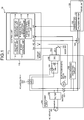
- Fig. 1 is a block diagram illustrating the overall configuration of an image processing apparatus 10 according to a first embodiment of the present invention.
- the image forming apparatus 10 generally includes a main power supply 100, a control board 110, and a fixing unit 120.
- the image forming apparatus 10 further includes a power supply switch (SW) 141, a door SW 142, and a triac (TRI) 143.
- SW power supply switch
- TRI triac
- the control board 110 controls the overall image forming apparatus 10.
- the control board 110 is mounted on a computer, to which a central processing unit (CPU), random access memory (RAM), read only memory (ROM), non-volatile RAM (NVRAM), application specific integrated circuit (ASIC), and an input/output interface, which are not shown, are connected via a bus.
- CPU central processing unit
- RAM random access memory
- ROM read only memory
- NVRAM non-volatile RAM
- ASIC application specific integrated circuit
- ASIC application specific integrated circuit
- the control board 110 controls on and off of the TRI 143 and an electromagnetic relay 106 provided between the main power supply 100 and the fixing unit 120, thereby performing temperature control of the fixing unit 120 and on/off control of a halogen heater 121.
- Other heater such as a ceramic heater, can be used in place of the halogen heater 121.
- a thermistor 122 provided near the halogen heater 121 of the fixing unit 120 measures surface temperature of the halogen heater 121.
- the control board 110 performs analog-to-digital (A/D) conversion of the surface temperature measured by the thermistor 122 to obtain the surface temperature of the halogen heater 121.
- the control board 110 controls on and off of the TRI 143 and the electromagnetic relay 106 for stabilization of the surface temperature.
- the DDC 105 which is a switching direct-current (DC)-DC converter, delivers a constant voltage Vcc to the control board 110 and a voltage of 24 volts to the electromagnetic relay 106.
- the electromagnetic relay 106 is operable to switch on a switch 107 and switch off the fixing unit 120 via the control board 110 when the door SW 142 of the image forming apparatus 10 is switched on.
- the electromagnetic relay 106 serves as a safety lock mechanism of the fixing unit 120.
- Zero-crossing detecting circuit 108 detects a zero-crossing point pertaining to the AC source 101.
- the control board 110 switches on and off the TRI 143 depending on the zero-crossing point. With the switch 107 on, the alternating current fed to the zero-crossing detecting circuit 108 crosses a zero-voltage point every half wavelength. Therefore, it is impossible for a transistor of the zero-crossing detecting circuit 108 to maintain on-state voltage. Upon detecting this state of the transistor, the zero-crossing detecting circuit 108 outputs a zero-crossing signal to the control board 110.
- the control board 110 includes a control unit 111 that controls the temperature of the halogen heater 121.
- the control unit 111 includes a half-wave control unit 112, a phase control unit 113, a heater-off-time measuring unit 114, a phase-control-execution determining unit 115, and a phase-control-time determining unit 116.
- the half-wave control unit 112 performs half-wave control, which is on/off control of power supply to the halogen heater 121 on a half-wave basis, according to a heater-on pattern having been set for each control cycle.
- the control cycle is a voltage cycle pertaining to the AC source 101 controlled by the control board 110 and is a cycle having a predetermined length.
- the on/off pattern for power supply to the halogen heater 121 is made such that each half wavelength, which is one-half of a wavelength, is allocated to either heater-on or heater-off.
- the half-wave control unit 112 first determines a duty ratio based on the surface temperature and a target temperature of the halogen heater 121.
- Fig. 2 is an explanatory diagram of the heater-on pattern table. As illustrated in Fig. 2 , a plurality of heater-on patterns that are individually associated with duty ratios are stored. For instance, according to a 40%-heater-on pattern, if each control cycle, which corresponds a voltage cycle of voltage control performed by the control board 110, is ten half wavelengths, electric power is supplied to the halogen heater 121 only during four half wavelengths specified by the pattern. Similarly, according to a 30%-heater-on pattern, electric power is supplied to the halogen heater 121 only during three half wavelengths specified by the pattern.
- the phase control unit 113 controls power supply to the halogen heater 121 by shifting phase of the voltage pertaining to the AC source 101.
- the image forming apparatus 10 it is allowed to control the halogen heater 121 by using the two methods, one of which is the half-wave control performed by the half-wave control unit 112 and the other is the phase control performed by the phase control unit 113.
- the heater-off-time measuring unit 114 start measurement of a heater-off period of time T when the halogen heater 121 is switched off. Specifically, the heater-off-time measuring unit 114 obtains a count value of zero crossings, which are detected by the zero-crossing detecting circuit 108 one by one over a period between switch-off and next switch-on of the halogen heater 121. The heater-off-time measuring unit 114 then calculates a period of time corresponding to the count value as the heater-off period of time T.
- the phase-control-execution determining unit 115 determines, based on the heater-off period of time T measured by the heater-off-time measuring unit 114, whether the phase control is to be performed by the phase control unit 113. Specifically, the phase-control-execution determining unit 115 performs comparison between a predetermined threshold value T0 for a heater-off period of time and the actually-measured heater-off period of time T, and if the heater-off period of time T is equal to or longer than the threshold value T0, determines that the phase control is to be performed. In contrast, if the heater-off period of time T is shorter than the threshold value T0, the phase-control-execution determining unit 115 determines that the phase control is to be skipped.
- duration of the phase control is desirably minimized. Accordingly, it is desirable to set ⁇ and ⁇ to such values that minimize the length of the execution period of time. The same goes for the threshold value T0 discussed above. There can be some cases where the heater-off period of time T is so short that the phase control is not required. From this point of view, the threshold value T0 is desirably set to such a value that minimizes duration of the phase control.
- Fig. 3 is flowchart illustrating a process procedure for heater control performed by the image forming apparatus 10 to control the halogen heater 121.
- the heater-off-time measuring unit 114 starts measurement of the heater-off period of time T (Step S11), and continues count for measurement of the heater-off period of time T until the halogen heater 121 is switched on (No at Step S12).
- the phase-control-execution determining unit 115 performs comparison between the heater-off period of time T and the threshold value T0, and if the heater-off period of time T is equal to or longer than the threshold value T0 (Yes at Step S13), the phase-control-execution determining unit 115 determines that the phase control is to be applied. In this case, the phase control unit 113 performs the phase control on the voltage for the halogen heater 121 according to an instruction fed from the phase-control-execution determining unit 115 (Step S14).
- the half-wave control unit 112 After the phase control has been performed for the execution period of time determined by the phase-control-time determining unit 116, the half-wave control unit 112 performs the half-wave control (Step S15). The half-wave control is continued until the halogen heater 121 is switched off (No at Step S16). When the halogen heater 121 is switched off (Yes at Step S16), control returns to Step S11 where measurement of the heater-off period of time is performed.
- the image forming apparatus 10 is configured such that the phase control is performed prior to the half-wave control only when the heater-off period of time is relatively long, duration of the phase control is minimized, which leads to reduction of flicker.
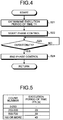
- Fig. 4 is a flowchart illustrating a detailed process procedure for the phase control (Step S14).
- the phase control is performed such that the phase-control-time determining unit 116 determines the execution period of time T1 of the phase control by using Equation (1) first (Step S21). Subsequently, the phase control unit 113 starts the phase control (Step S22), and continues the phase control until duration of the phase control performed by the phase control unit 113 becomes equal to the execution period of time T1 (No at Step S23). When the duration has become equal to or longer than the execution period of time T1 (Yes at Step S23), the phase control unit 113 stops the phase control (Step S24).
- the image forming apparatus 10 according to the first embodiment is configured such that when the heater-off period of time is equal to or longer than a predetermined period of time, the phase control is performed immediately after switch-on of the heater, and thereafter the half-wave control is performed. Accordingly, the inrush current that flows immediately after the switch-on of the heater in the case where all half-waves are allocated to the heater-on during an initial period after start of the heater-on/off control can be achieved. Furthermore, it is known that execution of the phase control causes flicker to occur. To this end, in the image forming apparatus 10 according to the first embodiment, the phase control is performed only for a minimum duration that depends on heater-off period of time. This allows flicker to be reduced and disturbance voltage to be decreased, thereby ensuring reliability.
- the control unit 111 can include an execution-time table.
- the phase-control-time determining unit 116 determines the execution period of time T1 based on the execution-time table.
- Fig. 5 is a table illustrating a data structure of the execution-time table in a simplified form. In the execution-time table, zero-crossing count values and execution period of time are associated with each other. Accordingly, the phase-control-time determining unit 116 refers to the execution-time table and determines application time associated with a counted zero-crossing count value as execution period of time, for a period of which the phase control is to be performed by the phase control unit 113.
- phase-control-execution determining unit 115 determines to skip the phase control.
- an execution period of time is preferably determined based on the execution-time table; however, if it is desirable to determine an execution period of time in smaller increments, the execution period of time is preferably determined by using Equation (1) as in the first embodiment. Note that equation for obtaining the execution period of time is not limited to that used in the embodiment, and any equation appropriate for characteristics of a heater can be employed.
- the heater-off-time measuring unit 114 continues count for measurement of the heater-off period of time T until the halogen heater 121 is switched on.
- a threshold value T2 for the heater-off period of time T is set and count for the heater-off period of time T is stopped when the heater-off period of time T has become equal to or longer than the threshold value T2
- the phase-control-execution determining unit 115 determines to perform the phase control
- the phase-control-time determining unit 116 determines a predetermined maximum execution period of time as an execution period of time, for a period of which the phase control is to be performed by the phase control unit 113.
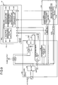
- Fig. 6 is a block diagram illustrating the overall configuration of an image processing apparatus 12 according to a second embodiment of the present invention.
- the image forming apparatus 12 includes a temperature sensor 510.
- the temperature sensor 510 measures the temperature near the fixing unit 120 corresponding to a fixing device.
- the temperature sensor 510 measures external temperature of the fixing unit 120; however, the temperature sensor 510 can alternatively be provided inside the fixing unit 120 to measure internal temperature of the fixing unit 120.
- a phase-control-execution determining unit 521 of a control unit 520 assigns a weight that depends on the temperature measured by the temperature sensor 510 to the heater-off period of time measured by the heater-off-time measuring unit 114. Specifically, when the measured temperature is equal to or higher than a predetermined threshold value T3, the phase-control-execution determining unit 521 obtains weighted heater-off period of time for use in comparison with the threshold value T0 by multiplying the measured heater-off period of time by 0.8, which is the value of weight (hereinafter, "weight value”), and determines whether to perform the phase control.
- weight value the value of weight
- a phase-control-time determining unit 522 assigns a weight that depends on the temperature measured by the temperature sensor 510 to the heater-off period of time measured by the heater-off-time measuring unit 114 as in the case of the phase-control-execution determining unit 521. Specifically, when the measured temperature is equal to or higher than the predetermined threshold value T3, the phase-control-time determining unit 522 obtains weighted heater-off period of time for use in determination of execution period of time by multiplying the measured heater-off period of time by 0.8, which is the weight value, and determines the execution period of time of the phase control by using Equation (1).
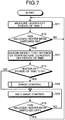
- Fig. 7 is a flowchart illustrating a process procedure for heater control.
- the phase-control-execution determining unit 521 assigns a weight that depends on the temperature measured by the temperature sensor 510 to heater-off period of time measured by the heater-off-time measuring unit 114 (Step S17). Specifically, when the temperature is equal to or higher than the threshold value T3, the phase-control-execution determining unit 521 obtains weighted heater-off period of time by multiplying the measured heater-off period of time by 0.8, and performs operations pertaining to Step S13 and subsequent steps as discussed above. Put another way, the phase-control-execution determining unit 521 determines whether to perform the phase control based on the weighted heater-off period of time, in which the temperature measured by the temperature sensor 510 is taken into account.
- Fig. 8 is a flowchart illustrating a detailed process procedure for the phase control (Step S14). Also in the phase control, the phase-control-time determining unit 522 assigns a weight that depends on the temperature measured by the temperature sensor 510 to the heater-off period of time measured by the heater-off-time measuring unit 114 first (Step S25). Specifically, when the temperature is equal to or higher than the threshold value T3, the phase-control-time determining unit 522 obtains weighted heater-off period of time by multiplying the measured heater-off period of time by 0.8, and performs operations pertaining to Step S21 and subsequent steps as discussed above. Put another way, the phase-control-time determining unit 522 determines the execution period of time of the phase control based on the weighted heater-off period of time, in which the temperature measured by the temperature sensor 510 is taken into account.
- Each of the phase-control-execution determining unit 521 and the phase-control-time determining unit 522 of the image forming apparatus 12 according to the second embodiment assigns a weight that depends on the temperature in the above discussion.
- Another configuration in which only any one of the phase-control-execution determining unit 521 and the phase-control-time determining unit 522 assigns a weight that depends on the temperature, can be employed as a first modification of the second embodiment. This modification allows various control operations to be performed.
- phase-control-execution determining unit 521 and the phase-control-time determining unit 522 use different threshold values for determination as to whether to perform weighting
- the weight value used by the phase-control-execution determining unit 521 and that used by the phase-control-time determining unit 522 can differ from each other. This allows evaluations to be made appropriately for each processing.
- Still another configuration in which when the temperature is lower than the threshold value T3, the weighted heater-off period of time is obtained by multiplying the measured heater-off period of time by such a weight value, e.g., 1.2, as to extend the length of the weighted heater-off period of time, can be employed as a third modification of the second embodiment.
- a weight value e.g., 1.2
- weighting is performed when the temperature is equal to or higher than the threshold value T3.
- Still another configuration in which, for instance, there has been set in advance an equation for calculating a weight value from the temperature such that the weight value decreases as the temperature increases, and heater-off period of time for use in determination as to whether to perform the phase control and determination of an execution period of time is determined by multiplying measured heater-off period of time by a weight value calculated by the using the equation, can be employed as a fourth modification of the second embodiment.
- Fig. 9 is a block diagram illustrating the overall configuration of an image processing apparatus 14 according to a third embodiment of the present invention.
- the image forming apparatus 14 includes a plurality of halogen heaters. An example where the image forming apparatus 14 includes two halogen heaters, or specifically a heater that heats a center portion of a fixing device and a heater that heats an end portion of the fixing device, will be described below.
- a fixing unit 130 includes a first halogen heater 121A and a second halogen heater 121B.
- the fixing unit 130 further includes a first thermistor 122A that measures surface temperature of the first halogen heater 121A and a second thermistor 122B that measures surface temperature of the second halogen heater 121B.
- the image forming apparatus 14 further includes a first TRI 143A and a second TRI 143B associated with the first halogen heater 121A and the second halogen heater 121B, respectively.
- a half-wave control unit 601 of a control unit 600 applies the half-wave control to the first halogen heater 121A and the half-wave control to the second halogen heater 121B.
- a phase control unit 602 performs the phase control for the first halogen heater 121A and the phase control for the second halogen heater 121B.
- a heater-off-period of time measuring unit 603 measures heater-off period time of the first halogen heater 121A and heater-off period of time of the second halogen heater 121B.
- a phase-control-execution determining unit 604 determines whether to apply the phase control to the first halogen heater 121A based on heater-off period of time T of the first halogen heater 121A, and further determines whether to apply the phase control to the second halogen heater 121B based on heater-off period of time T of the second halogen heater 121B.
- a phase-control-time determining unit 605 determines an execution period of time of the phase control for the first halogen heater 121A based on the heater-off period of time T of the first halogen heater 121A, and further determines an execution period of time of the phase control for the second halogen heater 121B based on the heater-off period of time T of the second halogen heater 121B.
- a priority heater is designated in advance and such heater control as to avoid concurrent execution of the phase control is employed.
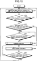
- Fig. 10 is a flowchart illustrating a process procedure for heater control to be applied to a halogen heater that is not designated as the priority heater.
- the heater-off-time measuring unit 603 starts measurement of the heater-off period of time T of the second halogen heater 121B (Step S31), and continues count for measurement of the heater-off period of time T until the second halogen heater 121B is switched on (No at Step S32).
- the phase-control-execution determining unit 604 performs comparison between the heater-off period of time T and the threshold value T0, and when the heater-off period of time T is equal to or longer than the threshold value T0 (Yes at Step S33), the phase-control-execution determining unit 604 further determines whether the first halogen heater 121A is under the phase control performed by the phase control unit 602. When the first halogen heater 121A is under the phase control (Yes at Step S34), the phase-control-execution determining unit 604 waits for completion of the phase control of the first halogen heater 121A without causing the phase control of the second halogen heater 121B to start.
- the phase control unit 602 performs the phase control for the second halogen heater 121B (Step S35).
- the heater control with the image forming apparatus 14 is configured such that while a priority halogen heater is under the phase control, the phase control is not applied to other halogen heater, and the phase control for the other halogen heater is started after completion of the phase control for the priority halogen heater. This leads to flicker reduction.
- heater control operations of the third embodiment are similar to heater control operations of the first embodiment discussed earlier with reference to Fig. 3 .
- Heater control operations to be performed on a halogen heater designated as the priority heater is similar to the heater control operations discussed earlier with reference to Fig. 3 .
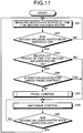
- Fig. 11 is a flowchart illustrating a process procedure for heater control according to the first modification of the third embodiment.
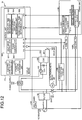
- Fig. 12 is a block diagram illustrating the overall configuration of an image processing apparatus 16 according to a fourth embodiment of the present invention.
- the image processing apparatus 16 according to the fourth embodiment is substantially identical with the image processing apparatus 14 according to the third embodiment, the image processing apparatus 16 differs from the image processing apparatus 14 in further determining which one of the halogen heaters is to be designated as the priority heater.
- the control board 110 of the image forming apparatus 16 includes, in addition to the control unit 600, an electric-power-value storage unit 701 and a priority-heater determining unit 702.
- the electric-power-value storage unit 701 stores electric power consumption of each of the halogen heaters 121A and 121B.
- the priority-heater determining unit 702 determines which one of the halogen heaters is to be designated as the priority heater based on the electric power consumption of each of the halogen heaters 121A and 121B stored in the electric-power-value storage unit 701.
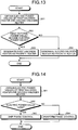
- Fig. 13 is a flowchart illustrating a process procedure for priority heater determination.
- the priority-heater determining unit 702 obtains a first electric power value, which is electric power consumption of the first halogen heater 121A, and a second electric power value, which is electric power consumption of the second halogen heater 121B, from the electric-power-value storage unit 701 first (Step S51). Subsequently, the priority-heater determining unit 702 performs comparison between the first electric power value and the second electric power value, and when the first electric power value is smaller than the second electric power value (Yes at Step S52), designates the first halogen heater 121A as the priority heater (Step S53).
- the priority-heater determining unit 702 designates the second halogen heater 121B as the priority heater (Step S54). Priority heater determination is completed with the designation.
- the image forming apparatus 16 is configured to determine the priority heater based on values of electric power consumption, thereby reducing flicker to a minimum.
- Fig. 14 is a flowchart illustrating a process procedure for electric-power-value determination according to the first modification of the fourth embodiment.
- the priority-heater determining unit 702 obtains the first electric power value of the first halogen heater 121A and the second electric power value of the second halogen heater 121B stored in the electric-power-value storage unit 701 (Step S61).
- the priority-heater determining unit 702 performs comparison between each of the electric power values and the threshold value ⁇ (W).
- the priority-heater determining unit 702 determines that the phase control is to be skipped (Step S63).
- the priority-heater determining unit 702 determines that the phase control is to be applied (Step S64).
- phase control is to be skipped when the phase-control-execution determining unit 604 of the control unit 600 has determined that the phase control is to be skipped.
- the phase control is skipped when electric power consumption is too small. Accordingly, flicker caused by unnecessary application of the phase control can be prevented.
- Still another configuration in which a weight that depends on electric power consumption is assigned to a heater-off period of time, can be employed as a second modification of the fourth embodiment.
- a configuration in which when electric power consumption is equal to or greater than a threshold value, a weighted heater-off period of time is obtained by multiplying measured heater-off period of time by 1.2, can be employed.
- a weight that extends the length of phase control time is assigned.
- whether to perform the phase control and an execution period of time of the phase control are determined based on the weighted heater-off period of time.
- whether to perform the phase control and an execution period of time of the phase control are determined based on the weighted heater-off period of time, in which the electric power consumption is taken into account. This allows execution of the phase control to be minimized.
- Each of the image forming apparatuses includes a control device, such as a CPU, a storage device, such as ROM and/or RAM, an external storage device, such as a hard disk drive (HDD) and/or a compact disk (CD) drive, a display device, and an input device, such as a keyboard and a mouse, and has a hardware configuration that utilizes a general computer.
- Control program to be executed by each of the image forming apparatuses of the embodiments can be provided as being recorded in a computer-readable recording medium such as a CD-ROM, a flexible disk (FD), a CD-recordable (CD-R), or a digital versatile disk (DVD) in an installable or executable format.
- control program to be executed by each of the image forming apparatuses of the embodiments can be configured to be stored in a computer connected to a network, such as the Internet, so as to be provided by being downloaded via the network. Still alternatively, the control program to be executed by each of the image forming apparatuses of the embodiments can be configured so as to be provided or distributed via a network, such as the Internet. Still alternatively, the control program to be executed by each of the image forming apparatuses of the embodiments can be configured to be provided as being pre-installed in ROM or the like.
- the control program to be executed by each of the image forming apparatuses of the embodiments has a module configuration that includes the units discussed above. From the viewpoint of actual hardware, the CPU (processor) reads the control program from the storage medium and executes the control program to load the units on a main memory device, whereby the units are generated on the main memory device.
- the image forming apparatus is applied to an MFP that has at least two functions of a copying function, a printer function, a scanner function, and a facsimile function; however, the image forming apparatus can be applied to any one of an MFP, a printer, a scanner, a facsimile machine, and a like image forming apparatus.
Landscapes
- Physics & Mathematics (AREA)
- General Physics & Mathematics (AREA)
- Fixing For Electrophotography (AREA)
- Control Or Security For Electrophotography (AREA)
Claims (15)
- Bilderzeugungsgerät (10; 12; 14; 16), Folgendes beinhaltend:eine Filtereinheit (120, 130);einen Erhitzer (121; 121A, 121B), welcher in der Fixiereinheit (120; 130) bereitgestellt ist;eine Wechselstromquelle (101), welche konfiguriert ist, um Wechselstrom an den Erhitzer (121,121A, 121B) anzulegen;eine Halbwellen-Steuerungseinheit (112; 601), welche konfiguriert ist, um ein Einschaltverhältnis basierend auf einer Oberflächentemperatur und einer Zieltemperatur des Erhitzers (121; 121A, 121 B) zu bestimmen und ein Erhitzer-Ein-Muster basierend auf dem bestimmten Einschaltverhältnis einzustellen, wobei das Erhitzer-Ein-Muster aus einem zuvor gespeicherten Erhitzer-Ein-Muster gewählt wird, welches dem vorbestimmten Einschaltverhältnis zugeordnet ist, und um eine Halbwellensteuerung durchzuführen, um den Erhitzer (121; 121A, 121 B) auf der Basis einer Halbwellenlänge zu steuern, gemäß dem Erhitzer-Ein-Muster, welches für jeden Steuerungszyklus, welcher eine vorbestimmte Länge besitzt, eingestellt ist;eine Messeinheit (114, 603), welche konfiguriert ist, wenn der Erhitzer (121, 121A, 121B) ausgeschaltet ist, einen Erhitzer-Aus-Zeitraum zu messen, welcher verstreicht, bis der Erhitzer wieder eingeschaltet wird;eine Bestimmungseinheit (115, 521, 604), welche konfiguriert ist, um, basierend auf dem gemessenen Erhitzer-Aus-Zeitraum, zu bestimmen, ob eine Phasensteuerung an der Wechselspannung vorgenommen werden muss, um den Erhitzer (121, 121A, 121B) zu steuern, wobei die Phasensteuerung durch Phasenverschiebung der Wechselspannung vorgenommen wird; undeine Phasensteuerungseinheit (113, 602), welche konfiguriert ist, um, wenn die Bestimmungseinheit (115, 521, 604) bestimmt, dass die Phasensteuerung durchgeführt werden muss, die Phasensteuerung nur über einen Zeitraum, welcher von dem gemessenen Erhitzer-Aus-Zeitraum nach Einschaltung des Erhitzers abhängt und vor Ausführung der Halbwellensteuerung, durchzuführen.
- Bilderzeugungsgerät (10, 12, 14, 16) nach Anspruch 1, bei welchem die Bestimmungseinheit (115, 521, 604) konfiguriert ist, um zu bestimmen, dass die Phasensteuerung durchgeführt werden muss, wenn der Erhitzer-Aus-Zeitraum gleich einem vorbestimmten Zeitraum oder länger als dieser ist.
- Bilderzeugungsgerät (10) nach Anspruch 1 oder 2, bei welchem die Phasensteuerungseinheit (113) konfiguriert ist, um die Phasensteuerung in solch einer Weise durchzuführen, dass, je länger der Erhitzer-Aus-Zeitraum ist, desto länger der Ausführungszeitraum der Phasensteuerung wird.
- Bilderzeugungsgerät (12) nach einem der Ansprüche 1 bis 3, zudem beinhaltend eine Temperaturmesseinheit (122, 510), welche konfiguriert ist, um eine von einer Innentemperatur und einer Außentemperatur der Fixiereinheit (120) zu messen, wobei die Bestimmungseinheit (521) konfiguriert ist zum Bestimmen, ebenso basierend auf der durch die Temperaturmesseinheit (122, 510) gemessenen Temperatur, ob die Phasensteuerung durchgeführt werden muss.
- Bilderzeugungsgerät (12) nach Anspruch 4, bei welchem die Phasensteuerungseinheit (113) konfiguriert ist, um die Phasensteuerung über einen Zeitraum durchzuführen, welcher zusätzlich von der durch die Temperaturmesseinheit gemessenen Temperatur (122, 510) abhängig ist.
- Bilderzeugungsgerät (12) nach Anspruch 5, bei welchem die Phasensteuerungseinheit (113) konfiguriert ist, um die Phasensteuerung über einen Zeitraum durchzuführen, welcher von einem gewichteten Erhitzer-Aus-Zeitraum abhängt, welcher durch Zuweisen eines Gewichtes erzielt wird, welches von dem Verhältnis Temperatur/Erhitzer-Aus-Zeitraum abhängt.
- Bilderzeugungsgerät (14; 16) nach einem der Ansprüche 1 bis 6, bei welchem
der Erhitzer eine Vielzahl von Erhitzern (121A, 121 B) beinhaltet,
die Halbwellensteuerungseinheit konfiguriert ist, um die Halbwellensteuerung für jeden der Erhitzer durchzuführen,
die Phasensteuerungseinheit (601) konfiguriert ist, um die Phasensteuerung für jeden der Erhitzer (121A, 121B) durchzuführen, und
die Bestimmungseinheit (604) zudem konfiguriert ist, um zu bestimmen, ob die Phasensteuerung durchgeführt werden muss, um zu verhindern, dass die Phasensteuerung gleichzeitig für die Erhitzer (121A, 121B) durchgeführt wird. - Bilderzeugungsgerät (16) nach Anspruch 7, zudem beinhaltend eine Speichereinheit für elektrische Werte (701), welche konfiguriert ist, um einen elektrischen Stromverbrauch eines jeden der Erhitzer (121A, 121B) zu speichern,
wobei die Bestimmungseinheit (604) konfiguriert ist, um ebenso basierend auf einer Stärke eines elektrischen Stromverbrauchs des Erhitzers (121A, 121B) zu bestimmen, ob die Phasensteuerung für einen jeden der Erhitzer (121A, 121B) durchgeführt werden muss. - Bilderzeugungsgerät (16) nach Anspruch 8, bei welchem die Phasensteuerungseinheit (602) konfiguriert ist, um die Phasensteuerung über einen Zeitraum durchzuführen, welcher zusätzlich von dem elektrischen Stromverbrauch abhängig ist.
- Bilderzeugungsgerät (10; 12; 14; 16) nach einem der Ansprüche 1 bis 9, bei welchem die Messeinheit (114; 603) eine Zeitschaltuhr umfasst, welche konfiguriert ist, um als den Erhitzer-Aus-Zeitraum die Dauer von einem Zeitpunkt, an welchem der Erhitzer (121; 121A, 121B) ausgeschaltet wird bis zu einem Zeitpunkt, an welchem der Erhitzer (121; 121A, 121B) eingeschaltet wird, zu messen.
- Bilderzeugungsgerät (10; 12; 14; 16) nach einem der Ansprüche 1 bis 9, zudem beinhaltend eine Nulldurchgangs-Erkennungsschaltung (108), welche konfiguriert ist, um einen Nulldurchgangspunkt der Wechselspannung zu erkennen,
wobei die Messeinheit (114; 603) konfiguriert ist, um Nulldurchgangspunkte zu zählen, welche durch die Nulldurchgangs-Erkennungsschaltung (108) einzeln von einem Zeitpunkt, an welchem der Erhitzer (121; 121A, 121B) ausgeschaltet wird bis zu einem Zeitpunkt, an welchem der Erhitzer (121; 121A, 121B) eingeschaltet wird, erkannt werden, um einen Zeitraum zu erzielen, welcher von einem gezählten Wert als dem Erhitzer-aus-Zeitraum abhängig ist. - Bilderzeugungsgerät (10; 12; 14; 16) nach einem der Ansprüche 1 bis 9, bei welchem die Messeinheit (114; 603) konfiguriert ist, um für jeden Steuerungszyklus eine Dauer von einem Zeitpunkt, an welchem der Erhitzer ausgeschaltet wird bis zu einem Zeitpunkt, an welchem der Erhitzer eingeschaltet wird, zu messen.
- Bilderzeugungsgerät (10; 12) nach einem der Ansprüche 1 bis 12, bei welchem die Phasensteuerungseinheit (113) konfiguriert ist, die Phasensteuerung nur für einen Zeitraum eines Ausführungszeitraums durchzuführen, welcher anhand des gemessenen Erhitzer-Aus-Zeitraums unter Verwendung einer vorbestimmten Gleichung berechnet wird, wobei die Gleichung zeigt, dass je länger der Erhitzer-Aus-Zeitraum ist, desto länger der Ausführungszeitraum wird.
- Bilderzeugungsgerät (10) nach einem der Ansprüche 1 bis 12, zudem beinhaltend eine Speichereinheit, welche konfiguriert ist, um darin den dem Ausführungszeitraum zugeordneten Erhitzer-Aus-Zeitraum zu speichern, wobei der Ausführungszeitraum so eingestellt wird, dass, je länger der Erhitzer-Aus-Zeitraum ist, desto länger der Ausführungszeitraum wird,
wobei die Phasensteuerungseinheit (113) konfiguriert ist, um die Phasensteuerung nur für den Ausführungszeitraum durchzuführen, welcher dem Erhitzer-Aus-Zeitraum in der Speicherungseinheit zugeordnet ist. - Steuerungsverfahren für einen Erhitzer, welches in einem Bilderzeugungsgerät (10; 12; 14; 16) ausgeführt werden soll, welches eine Fixiereinheit (120; 130), einen in der Fixiereinheit (120; 130) bereitgestellten Erhitzer (121; 121A, 121B), eine Wechselstromquelle (101), welche Wechselstrom an den Erhitzer (121; 121A, 121B) anlegt, eine Halbwellensteuerungseinheit (112; 601), eine Messeinheit (114; 603), eine Bestimmungseinheit (115; 521; 604) und eine Phasensteuerungseinheit (113; 602) beinhaltet, wobei das Steuerungsverfahren für einen Erhitzer folgendes beinhaltet:Bestimmen eines Einschaltverhältnisses, basierend auf einer Oberflächentemperatur und einer Zieltemperatur des Erhitzers (121; 121A, 121B) und Einstellen eines Erhitzer-Ein-Musters, basierend auf dem bestimmten Einschaltverhältnis, wobei das Erhitzer-Ein-Muster aus einem zuvor gespeicherten Erhitzer-Ein-Muster gewählt wird, welches dem vorbestimmten Einschaltverhältnis zugeordnet ist;Durchführen, unter Verwendung der Halbwellensteuerungseinheit (112; 601), einer Halbwellensteuerung zum Steuern des Erhitzers (121; 121A, 121B) auf der Basis einer Halbwellenlänge, gemäß einem Erhitzer-Ein/Aus-Muster, welches für jeden Steuerungszyklus, welcher eine vorbestimmte Länge besitzt, eingestellt ist;Messen, unter Verwendung der Messeinheit (114, 603), wenn der Erhitzer (121; 121A, 121B) ausgeschaltet ist, eines Erhitzer-Aus-Zeitraums, welcher verstreicht, bis der Erhitzer wieder eingeschaltet wird;Bestimmen, unter Verwendung der Bestimmungseinheit (115; 521; 604), basierend auf dem gemessenen Erhitzer-Aus-Zeitraum, ob eine Phasensteuerung an der Wechselspannung vorgenommen werden muss, um den Erhitzer (121, 121A, 121 B) zu steuern, wobei die Phasensteuerung durch Phasenverschiebung der Wechselspannung vorgenommen wird; undDurchführen, unter Verwendung der Phasensteuerungseinheit (113, 602), wenn bestimmt wurde, dass die Phasensteuerung durchgeführt werden muss, der Phasensteuerung nur über einen Zeitraum, welcher von dem gemessenen Erhitzer-Aus-Zeitraum, der bei der Messung nach Einschaltung des Erhitzers und vor Ausführung der Halbwellensteuerung gemessen wurde, abhängig ist.
Applications Claiming Priority (1)
| Application Number | Priority Date | Filing Date | Title |
|---|---|---|---|
| JP2009147945A JP5359594B2 (ja) | 2009-06-22 | 2009-06-22 | 画像形成装置、ヒータ制御方法およびプログラム |
Publications (3)
| Publication Number | Publication Date |
|---|---|
| EP2278417A2 EP2278417A2 (de) | 2011-01-26 |
| EP2278417A3 EP2278417A3 (de) | 2011-06-29 |
| EP2278417B1 true EP2278417B1 (de) | 2020-06-24 |
Family
ID=43235362
Family Applications (1)
| Application Number | Title | Priority Date | Filing Date |
|---|---|---|---|
| EP10251117.7A Not-in-force EP2278417B1 (de) | 2009-06-22 | 2010-06-21 | Bilderzeugungsvorrichtung und Heizungssteuerverfahren |
Country Status (3)
| Country | Link |
|---|---|
| US (1) | US8260165B2 (de) |
| EP (1) | EP2278417B1 (de) |
| JP (1) | JP5359594B2 (de) |
Families Citing this family (11)
| Publication number | Priority date | Publication date | Assignee | Title |
|---|---|---|---|---|
| JP5471618B2 (ja) * | 2010-03-05 | 2014-04-16 | 株式会社リコー | ヒータ制御装置、画像形成装置、ヒータ制御方法およびプログラム |
| JP5516097B2 (ja) * | 2010-06-09 | 2014-06-11 | 株式会社リコー | 画像形成装置、ヒータ制御方法およびプログラム |
| JP5744497B2 (ja) * | 2010-12-09 | 2015-07-08 | キヤノン株式会社 | 画像形成装置 |
| JP2014085430A (ja) * | 2012-10-22 | 2014-05-12 | Ricoh Co Ltd | 定着装置および画像形成装置 |
| JP5712186B2 (ja) * | 2012-10-31 | 2015-05-07 | 京セラドキュメントソリューションズ株式会社 | 状態検知装置及びこれを備えた画像形成装置 |
| WO2015183274A1 (en) | 2014-05-29 | 2015-12-03 | Hewlett-Packard Development Company, L.P. | Power management |
| JP6269627B2 (ja) * | 2015-09-18 | 2018-01-31 | コニカミノルタ株式会社 | 定着装置及び画像形成装置 |
| JP6414039B2 (ja) * | 2015-12-11 | 2018-10-31 | コニカミノルタ株式会社 | 画像形成装置 |
| US10534295B2 (en) | 2017-05-18 | 2020-01-14 | Canon Kabushiki Kaisha | Fixing apparatus for fixing a toner image to a sheet, the fixing apparatus being operable in relation to either of a first nominal voltage of a second nominal voltage as an alternating voltage of a commercial alternating current power supply |
| KR20200014067A (ko) * | 2018-07-31 | 2020-02-10 | 휴렛-팩커드 디벨롭먼트 컴퍼니, 엘.피. | 정착기의 구동 제어 방법 |
| JP7567641B2 (ja) * | 2021-04-21 | 2024-10-16 | 沖電気工業株式会社 | 画像形成装置 |
Family Cites Families (16)
| Publication number | Priority date | Publication date | Assignee | Title |
|---|---|---|---|---|
| JPH0727477Y2 (ja) | 1987-07-03 | 1995-06-21 | 株式会社リコー | 複写機における熱ロ−ラ定着装置の定着温度制御装置 |
| DE69707180T2 (de) * | 1996-03-21 | 2002-05-02 | Canon K.K., Tokio/Tokyo | Heizgerät für ein Bild |
| JP3847951B2 (ja) * | 1997-04-30 | 2006-11-22 | キヤノン株式会社 | 加熱制御装置 |
| JPH1124487A (ja) * | 1997-06-27 | 1999-01-29 | Mita Ind Co Ltd | 発熱体の駆動制御方法 |
| JP3316170B2 (ja) | 1997-09-18 | 2002-08-19 | コピア株式会社 | 定着ヒータの制御方法および画像形成装置 |
| JP2000267496A (ja) * | 1999-03-17 | 2000-09-29 | Canon Inc | 定着装置、及びこれを備えた画像形成装置 |
| JP2001005537A (ja) * | 1999-06-25 | 2001-01-12 | Sharp Corp | 加熱制御装置 |
| US6633726B2 (en) * | 1999-07-27 | 2003-10-14 | Kenneth A. Bradenbaugh | Method of controlling the temperature of water in a water heater |
| JP2002006655A (ja) * | 2000-06-21 | 2002-01-11 | Canon Inc | 定着器駆動装置 |
| JP2004191710A (ja) * | 2002-12-12 | 2004-07-08 | Kyocera Mita Corp | 定着装置及びこれを備えた画像形成装置 |
| JP2005195640A (ja) * | 2003-12-26 | 2005-07-21 | Canon Finetech Inc | 定着ヒータ制御方法および画像形成装置 |
| JP2006184329A (ja) | 2004-12-24 | 2006-07-13 | Ricoh Co Ltd | 画像形成装置 |
| JP4539453B2 (ja) * | 2005-06-17 | 2010-09-08 | 富士ゼロックス株式会社 | ヒータ制御装置、画像形成装置、ヒータ制御方法及びプログラム |
| JP2007305400A (ja) | 2006-05-11 | 2007-11-22 | Ricoh Co Ltd | 誘導加熱による発熱装置、及び画像形成装置 |
| US8532516B2 (en) * | 2007-04-12 | 2013-09-10 | Ricoh Company, Ltd. | Fixing device, image forming apparatus, and heating control method |
| JP5068612B2 (ja) | 2007-09-14 | 2012-11-07 | 株式会社リコー | 画像形成装置とその制御方法 |
-
2009
- 2009-06-22 JP JP2009147945A patent/JP5359594B2/ja active Active
-
2010
- 2010-06-21 EP EP10251117.7A patent/EP2278417B1/de not_active Not-in-force
- 2010-06-21 US US12/819,461 patent/US8260165B2/en active Active
Non-Patent Citations (1)
| Title |
|---|
| None * |
Also Published As
| Publication number | Publication date |
|---|---|
| JP2011002782A (ja) | 2011-01-06 |
| EP2278417A3 (de) | 2011-06-29 |
| EP2278417A2 (de) | 2011-01-26 |
| US8260165B2 (en) | 2012-09-04 |
| JP5359594B2 (ja) | 2013-12-04 |
| US20100322656A1 (en) | 2010-12-23 |
Similar Documents
| Publication | Publication Date | Title |
|---|---|---|
| EP2278417B1 (de) | Bilderzeugungsvorrichtung und Heizungssteuerverfahren | |
| US8521049B2 (en) | Heater controller, image forming apparatus, method for controlling heater | |
| US8530800B2 (en) | Heater control device, image forming apparatus, and computer program product | |
| JP6700704B2 (ja) | 電力供給装置及び画像形成装置 | |
| KR100503843B1 (ko) | 정착 장치 | |
| US8835815B2 (en) | Heater control device, image forming apparatus, and heater controlling method | |
| JP5321380B2 (ja) | ヒータ制御装置、画像形成装置およびプログラム | |
| JP5068968B2 (ja) | 電源電圧制御装置、電源電圧制御方法、その方法をコンピュータに実行させるプログラム、および画像形成装置 | |
| KR20170045954A (ko) | 화상형성장치 및 그의 제어 방법 | |
| JP5614188B2 (ja) | ヒータ制御装置、画像形成装置およびプログラム | |
| JP2024016197A (ja) | ヒータ制御装置、画像形成装置、ヒータの制御方法およびヒータの制御プログラム | |
| JP5397151B2 (ja) | ヒータ制御装置、画像形成装置、ヒータ制御方法およびプログラム | |
| JP2011064824A (ja) | ヒータ制御装置、画像形成装置、ヒータ制御方法およびヒータ制御プログラム | |
| JP5982818B2 (ja) | 電圧出力装置、画像形成装置 | |
| JP5446645B2 (ja) | ヒータ制御装置、ヒータ制御方法、およびプログラム | |
| JP2005148273A (ja) | 画像形成装置 | |
| JP2005012977A (ja) | 電力制御装置及び画像形成装置 | |
| JP5906454B2 (ja) | 誘導加熱装置とその制御方法 | |
| JP2018173528A (ja) | 画像形成装置、ヒータの制御方法、およびプログラム | |
| JP5066413B2 (ja) | ヒータ制御装置およびヒータ制御方法 | |
| JP4606825B2 (ja) | 電源装置、画像形成装置、電源制御方法、電源制御プログラム、記録媒体 | |
| JP2021110844A (ja) | ヒータ制御装置、定着装置、画像形成装置、及び、ヒータ制御方法 | |
| JP2018173530A (ja) | 画像形成装置、ヒータの制御方法、およびプログラム |
Legal Events
| Date | Code | Title | Description |
|---|---|---|---|
| PUAI | Public reference made under article 153(3) epc to a published international application that has entered the european phase |
Free format text: ORIGINAL CODE: 0009012 |
|
| 17P | Request for examination filed |
Effective date: 20100705 |
|
| AK | Designated contracting states |
Kind code of ref document: A2 Designated state(s): AL AT BE BG CH CY CZ DE DK EE ES FI FR GB GR HR HU IE IS IT LI LT LU LV MC MK MT NL NO PL PT RO SE SI SK SM TR |
|
| AX | Request for extension of the european patent |
Extension state: BA ME RS |
|
| PUAL | Search report despatched |
Free format text: ORIGINAL CODE: 0009013 |
|
| AK | Designated contracting states |
Kind code of ref document: A3 Designated state(s): AL AT BE BG CH CY CZ DE DK EE ES FI FR GB GR HR HU IE IS IT LI LT LU LV MC MK MT NL NO PL PT RO SE SI SK SM TR |
|
| AX | Request for extension of the european patent |
Extension state: BA ME RS |
|
| RIC1 | Information provided on ipc code assigned before grant |
Ipc: G03G 15/00 20060101ALI20110525BHEP Ipc: G03G 15/20 20060101AFI20101206BHEP |
|
| 17Q | First examination report despatched |
Effective date: 20150202 |
|
| STAA | Information on the status of an ep patent application or granted ep patent |
Free format text: STATUS: EXAMINATION IS IN PROGRESS |
|
| GRAP | Despatch of communication of intention to grant a patent |
Free format text: ORIGINAL CODE: EPIDOSNIGR1 |
|
| STAA | Information on the status of an ep patent application or granted ep patent |
Free format text: STATUS: GRANT OF PATENT IS INTENDED |
|
| RIN1 | Information on inventor provided before grant (corrected) |
Inventor name: CHOSOKABE, KIRIKO Inventor name: TAKUMA, KASAI Inventor name: NEMOTO, EIJI Inventor name: OKADA, NORIKAZU |
|
| INTG | Intention to grant announced |
Effective date: 20200203 |
|
| GRAS | Grant fee paid |
Free format text: ORIGINAL CODE: EPIDOSNIGR3 |
|
| GRAA | (expected) grant |
Free format text: ORIGINAL CODE: 0009210 |
|
| STAA | Information on the status of an ep patent application or granted ep patent |
Free format text: STATUS: THE PATENT HAS BEEN GRANTED |
|
| AK | Designated contracting states |
Kind code of ref document: B1 Designated state(s): AL AT BE BG CH CY CZ DE DK EE ES FI FR GB GR HR HU IE IS IT LI LT LU LV MC MK MT NL NO PL PT RO SE SI SK SM TR |
|
| REG | Reference to a national code |
Ref country code: GB Ref legal event code: FG4D |
|
| REG | Reference to a national code |
Ref country code: CH Ref legal event code: EP |
|
| REG | Reference to a national code |
Ref country code: DE Ref legal event code: R096 Ref document number: 602010064712 Country of ref document: DE |
|
| REG | Reference to a national code |
Ref country code: AT Ref legal event code: REF Ref document number: 1284498 Country of ref document: AT Kind code of ref document: T Effective date: 20200715 |
|
| REG | Reference to a national code |
Ref country code: IE Ref legal event code: FG4D |
|
| REG | Reference to a national code |
Ref country code: NL Ref legal event code: FP |
|
| PG25 | Lapsed in a contracting state [announced via postgrant information from national office to epo] |
Ref country code: GR Free format text: LAPSE BECAUSE OF FAILURE TO SUBMIT A TRANSLATION OF THE DESCRIPTION OR TO PAY THE FEE WITHIN THE PRESCRIBED TIME-LIMIT Effective date: 20200925 Ref country code: NO Free format text: LAPSE BECAUSE OF FAILURE TO SUBMIT A TRANSLATION OF THE DESCRIPTION OR TO PAY THE FEE WITHIN THE PRESCRIBED TIME-LIMIT Effective date: 20200924 Ref country code: SE Free format text: LAPSE BECAUSE OF FAILURE TO SUBMIT A TRANSLATION OF THE DESCRIPTION OR TO PAY THE FEE WITHIN THE PRESCRIBED TIME-LIMIT Effective date: 20200624 Ref country code: LT Free format text: LAPSE BECAUSE OF FAILURE TO SUBMIT A TRANSLATION OF THE DESCRIPTION OR TO PAY THE FEE WITHIN THE PRESCRIBED TIME-LIMIT Effective date: 20200624 Ref country code: FI Free format text: LAPSE BECAUSE OF FAILURE TO SUBMIT A TRANSLATION OF THE DESCRIPTION OR TO PAY THE FEE WITHIN THE PRESCRIBED TIME-LIMIT Effective date: 20200624 |
|
| REG | Reference to a national code |
Ref country code: LT Ref legal event code: MG4D |
|
| PG25 | Lapsed in a contracting state [announced via postgrant information from national office to epo] |
Ref country code: LV Free format text: LAPSE BECAUSE OF FAILURE TO SUBMIT A TRANSLATION OF THE DESCRIPTION OR TO PAY THE FEE WITHIN THE PRESCRIBED TIME-LIMIT Effective date: 20200624 Ref country code: HR Free format text: LAPSE BECAUSE OF FAILURE TO SUBMIT A TRANSLATION OF THE DESCRIPTION OR TO PAY THE FEE WITHIN THE PRESCRIBED TIME-LIMIT Effective date: 20200624 Ref country code: BG Free format text: LAPSE BECAUSE OF FAILURE TO SUBMIT A TRANSLATION OF THE DESCRIPTION OR TO PAY THE FEE WITHIN THE PRESCRIBED TIME-LIMIT Effective date: 20200924 |
|
| REG | Reference to a national code |
Ref country code: AT Ref legal event code: MK05 Ref document number: 1284498 Country of ref document: AT Kind code of ref document: T Effective date: 20200624 |
|
| PG25 | Lapsed in a contracting state [announced via postgrant information from national office to epo] |
Ref country code: AL Free format text: LAPSE BECAUSE OF FAILURE TO SUBMIT A TRANSLATION OF THE DESCRIPTION OR TO PAY THE FEE WITHIN THE PRESCRIBED TIME-LIMIT Effective date: 20200624 |
|
| PG25 | Lapsed in a contracting state [announced via postgrant information from national office to epo] |
Ref country code: PT Free format text: LAPSE BECAUSE OF FAILURE TO SUBMIT A TRANSLATION OF THE DESCRIPTION OR TO PAY THE FEE WITHIN THE PRESCRIBED TIME-LIMIT Effective date: 20201026 Ref country code: ES Free format text: LAPSE BECAUSE OF FAILURE TO SUBMIT A TRANSLATION OF THE DESCRIPTION OR TO PAY THE FEE WITHIN THE PRESCRIBED TIME-LIMIT Effective date: 20200624 Ref country code: RO Free format text: LAPSE BECAUSE OF FAILURE TO SUBMIT A TRANSLATION OF THE DESCRIPTION OR TO PAY THE FEE WITHIN THE PRESCRIBED TIME-LIMIT Effective date: 20200624 Ref country code: CZ Free format text: LAPSE BECAUSE OF FAILURE TO SUBMIT A TRANSLATION OF THE DESCRIPTION OR TO PAY THE FEE WITHIN THE PRESCRIBED TIME-LIMIT Effective date: 20200624 Ref country code: IT Free format text: LAPSE BECAUSE OF FAILURE TO SUBMIT A TRANSLATION OF THE DESCRIPTION OR TO PAY THE FEE WITHIN THE PRESCRIBED TIME-LIMIT Effective date: 20200624 Ref country code: EE Free format text: LAPSE BECAUSE OF FAILURE TO SUBMIT A TRANSLATION OF THE DESCRIPTION OR TO PAY THE FEE WITHIN THE PRESCRIBED TIME-LIMIT Effective date: 20200624 Ref country code: AT Free format text: LAPSE BECAUSE OF FAILURE TO SUBMIT A TRANSLATION OF THE DESCRIPTION OR TO PAY THE FEE WITHIN THE PRESCRIBED TIME-LIMIT Effective date: 20200624 Ref country code: SM Free format text: LAPSE BECAUSE OF FAILURE TO SUBMIT A TRANSLATION OF THE DESCRIPTION OR TO PAY THE FEE WITHIN THE PRESCRIBED TIME-LIMIT Effective date: 20200624 |
|
| PG25 | Lapsed in a contracting state [announced via postgrant information from national office to epo] |
Ref country code: IS Free format text: LAPSE BECAUSE OF FAILURE TO SUBMIT A TRANSLATION OF THE DESCRIPTION OR TO PAY THE FEE WITHIN THE PRESCRIBED TIME-LIMIT Effective date: 20201024 Ref country code: SK Free format text: LAPSE BECAUSE OF FAILURE TO SUBMIT A TRANSLATION OF THE DESCRIPTION OR TO PAY THE FEE WITHIN THE PRESCRIBED TIME-LIMIT Effective date: 20200624 Ref country code: PL Free format text: LAPSE BECAUSE OF FAILURE TO SUBMIT A TRANSLATION OF THE DESCRIPTION OR TO PAY THE FEE WITHIN THE PRESCRIBED TIME-LIMIT Effective date: 20200624 |
|
| REG | Reference to a national code |
Ref country code: DE Ref legal event code: R097 Ref document number: 602010064712 Country of ref document: DE |
|
| PG25 | Lapsed in a contracting state [announced via postgrant information from national office to epo] |
Ref country code: DK Free format text: LAPSE BECAUSE OF FAILURE TO SUBMIT A TRANSLATION OF THE DESCRIPTION OR TO PAY THE FEE WITHIN THE PRESCRIBED TIME-LIMIT Effective date: 20200624 |
|
| PLBE | No opposition filed within time limit |
Free format text: ORIGINAL CODE: 0009261 |
|
| STAA | Information on the status of an ep patent application or granted ep patent |
Free format text: STATUS: NO OPPOSITION FILED WITHIN TIME LIMIT |
|
| 26N | No opposition filed |
Effective date: 20210325 |
|
| PG25 | Lapsed in a contracting state [announced via postgrant information from national office to epo] |
Ref country code: SI Free format text: LAPSE BECAUSE OF FAILURE TO SUBMIT A TRANSLATION OF THE DESCRIPTION OR TO PAY THE FEE WITHIN THE PRESCRIBED TIME-LIMIT Effective date: 20200624 |
|
| PG25 | Lapsed in a contracting state [announced via postgrant information from national office to epo] |
Ref country code: MC Free format text: LAPSE BECAUSE OF FAILURE TO SUBMIT A TRANSLATION OF THE DESCRIPTION OR TO PAY THE FEE WITHIN THE PRESCRIBED TIME-LIMIT Effective date: 20200624 |
|
| REG | Reference to a national code |
Ref country code: CH Ref legal event code: PL |
|
| REG | Reference to a national code |
Ref country code: BE Ref legal event code: MM Effective date: 20210630 |
|
| PG25 | Lapsed in a contracting state [announced via postgrant information from national office to epo] |
Ref country code: LU Free format text: LAPSE BECAUSE OF NON-PAYMENT OF DUE FEES Effective date: 20210621 |
|
| PG25 | Lapsed in a contracting state [announced via postgrant information from national office to epo] |
Ref country code: LI Free format text: LAPSE BECAUSE OF NON-PAYMENT OF DUE FEES Effective date: 20210630 Ref country code: IE Free format text: LAPSE BECAUSE OF NON-PAYMENT OF DUE FEES Effective date: 20210621 Ref country code: CH Free format text: LAPSE BECAUSE OF NON-PAYMENT OF DUE FEES Effective date: 20210630 |
|
| PG25 | Lapsed in a contracting state [announced via postgrant information from national office to epo] |
Ref country code: BE Free format text: LAPSE BECAUSE OF NON-PAYMENT OF DUE FEES Effective date: 20210630 |
|
| PGFP | Annual fee paid to national office [announced via postgrant information from national office to epo] |
Ref country code: NL Payment date: 20220620 Year of fee payment: 13 Ref country code: GB Payment date: 20220622 Year of fee payment: 13 Ref country code: DE Payment date: 20220620 Year of fee payment: 13 |
|
| PGFP | Annual fee paid to national office [announced via postgrant information from national office to epo] |
Ref country code: FR Payment date: 20220628 Year of fee payment: 13 |
|
| PG25 | Lapsed in a contracting state [announced via postgrant information from national office to epo] |
Ref country code: HU Free format text: LAPSE BECAUSE OF FAILURE TO SUBMIT A TRANSLATION OF THE DESCRIPTION OR TO PAY THE FEE WITHIN THE PRESCRIBED TIME-LIMIT; INVALID AB INITIO Effective date: 20100621 Ref country code: CY Free format text: LAPSE BECAUSE OF FAILURE TO SUBMIT A TRANSLATION OF THE DESCRIPTION OR TO PAY THE FEE WITHIN THE PRESCRIBED TIME-LIMIT Effective date: 20200624 |
|
| REG | Reference to a national code |
Ref country code: DE Ref legal event code: R119 Ref document number: 602010064712 Country of ref document: DE |
|
| REG | Reference to a national code |
Ref country code: NL Ref legal event code: MM Effective date: 20230701 |
|
| GBPC | Gb: european patent ceased through non-payment of renewal fee |
Effective date: 20230621 |
|
| PG25 | Lapsed in a contracting state [announced via postgrant information from national office to epo] |
Ref country code: NL Free format text: LAPSE BECAUSE OF NON-PAYMENT OF DUE FEES Effective date: 20230701 |
|
| PG25 | Lapsed in a contracting state [announced via postgrant information from national office to epo] |
Ref country code: MK Free format text: LAPSE BECAUSE OF FAILURE TO SUBMIT A TRANSLATION OF THE DESCRIPTION OR TO PAY THE FEE WITHIN THE PRESCRIBED TIME-LIMIT Effective date: 20200624 Ref country code: DE Free format text: LAPSE BECAUSE OF NON-PAYMENT OF DUE FEES Effective date: 20240103 Ref country code: GB Free format text: LAPSE BECAUSE OF NON-PAYMENT OF DUE FEES Effective date: 20230621 |
|
| PG25 | Lapsed in a contracting state [announced via postgrant information from national office to epo] |
Ref country code: FR Free format text: LAPSE BECAUSE OF NON-PAYMENT OF DUE FEES Effective date: 20230630 |
|
| PG25 | Lapsed in a contracting state [announced via postgrant information from national office to epo] |
Ref country code: MT Free format text: LAPSE BECAUSE OF FAILURE TO SUBMIT A TRANSLATION OF THE DESCRIPTION OR TO PAY THE FEE WITHIN THE PRESCRIBED TIME-LIMIT Effective date: 20200624 |
|
| PG25 | Lapsed in a contracting state [announced via postgrant information from national office to epo] |
Ref country code: TR Free format text: LAPSE BECAUSE OF FAILURE TO SUBMIT A TRANSLATION OF THE DESCRIPTION OR TO PAY THE FEE WITHIN THE PRESCRIBED TIME-LIMIT Effective date: 20200624 |