EP2277640B1 - Rundläuferrollenlanlage - Google Patents
Rundläuferrollenlanlage Download PDFInfo
- Publication number
- EP2277640B1 EP2277640B1 EP09732948.6A EP09732948A EP2277640B1 EP 2277640 B1 EP2277640 B1 EP 2277640B1 EP 09732948 A EP09732948 A EP 09732948A EP 2277640 B1 EP2277640 B1 EP 2277640B1
- Authority
- EP
- European Patent Office
- Prior art keywords
- take
- strip
- drum
- roller
- carousel reel
- Prior art date
- Legal status (The legal status is an assumption and is not a legal conclusion. Google has not performed a legal analysis and makes no representation as to the accuracy of the status listed.)
- Active
Links
Images


Classifications
-
- B—PERFORMING OPERATIONS; TRANSPORTING
- B21—MECHANICAL METAL-WORKING WITHOUT ESSENTIALLY REMOVING MATERIAL; PUNCHING METAL
- B21C—MANUFACTURE OF METAL SHEETS, WIRE, RODS, TUBES, PROFILES OR LIKE SEMI-MANUFACTURED PRODUCTS OTHERWISE THAN BY ROLLING; AUXILIARY OPERATIONS USED IN CONNECTION WITH METAL-WORKING WITHOUT ESSENTIALLY REMOVING MATERIAL
- B21C47/00—Winding-up, coiling or winding-off metal wire, metal band or other flexible metal material characterised by features relevant to metal processing only
- B21C47/24—Transferring coils to or from winding apparatus or to or from operative position therein; Preventing uncoiling during transfer
- B21C47/245—Devices for the replacement of full reels by empty reels or vice versa, without considerable loss of time
-
- B—PERFORMING OPERATIONS; TRANSPORTING
- B21—MECHANICAL METAL-WORKING WITHOUT ESSENTIALLY REMOVING MATERIAL; PUNCHING METAL
- B21C—MANUFACTURE OF METAL SHEETS, WIRE, RODS, TUBES, PROFILES OR LIKE SEMI-MANUFACTURED PRODUCTS OTHERWISE THAN BY ROLLING; AUXILIARY OPERATIONS USED IN CONNECTION WITH METAL-WORKING WITHOUT ESSENTIALLY REMOVING MATERIAL
- B21C47/00—Winding-up, coiling or winding-off metal wire, metal band or other flexible metal material characterised by features relevant to metal processing only
- B21C47/02—Winding-up or coiling
- B21C47/04—Winding-up or coiling on or in reels or drums, without using a moving guide
- B21C47/06—Winding-up or coiling on or in reels or drums, without using a moving guide with loaded rollers, bolts, or equivalent means holding the material on the reel or drum
-
- B—PERFORMING OPERATIONS; TRANSPORTING
- B21—MECHANICAL METAL-WORKING WITHOUT ESSENTIALLY REMOVING MATERIAL; PUNCHING METAL
- B21C—MANUFACTURE OF METAL SHEETS, WIRE, RODS, TUBES, PROFILES OR LIKE SEMI-MANUFACTURED PRODUCTS OTHERWISE THAN BY ROLLING; AUXILIARY OPERATIONS USED IN CONNECTION WITH METAL-WORKING WITHOUT ESSENTIALLY REMOVING MATERIAL
- B21C47/00—Winding-up, coiling or winding-off metal wire, metal band or other flexible metal material characterised by features relevant to metal processing only
- B21C47/34—Feeding or guiding devices not specially adapted to a particular type of apparatus
Definitions
- the present invention relates to a carousel reel facility capable of continuously taking up a transported strip by alternately switching take-up positions of two rotatable take-up drums revolving with a carousel reel.
- a cold-rolled strip of soft steel, high-tensile steel, or the like is rolled in a single pass by continuous tandem rolling in order to achieve high efficiency and high yield.
- a preceding strip and a following strip each unwound from a coil of a hot rolled strip are connected together to form a continuous strip.
- this strip is continuously fed to a continuous tandem rolling mill to perform cold rolling.
- the strip is sequentially passed through rolling stands of the continuous tandem rolling mill to be rolled to a target thickness. Subsequently, the rolled strip is again taken up in a coil shape on the delivery side of the continuous tandem rolling mill, where the connecting portion of the preceding strip and the following strip is cut.
- the continuous tandem rolling mill is provided, on the delivery side, with a take-up facility which is capable of continuously taking up the cut preceding strip and following strip in a coil shape.
- a take-up facility which is capable of continuously taking up the cut preceding strip and following strip in a coil shape.
- take-up facilities one in which two rotatable take-up drums revolve with a carousel reel (called a carousel reel facility below) is recently widely used from the viewpoint of productivity and reduction of facility cost.
- a first take-up drum 22 which is disposed at a take-up start position on an upstream side starts to take up a preceding strip Sf. Then, a carousel reel 21 is revolved during the taking-up to move the first take-up drum 22 to a take-up completion position on a downstream side and a second take-up drum 23 to the take-up start position.
- a trailing edge of the preceding strip Sf is cut by cutting blades 121a, 121b of respective drum shears 12a, 12b in this state. Then, a leading edge of a following strip Sb is taken-up by the second take-up drum 23.
- Patent Documents 1 and 2 each disclose a carousel reel facility applied to a continuous finishing facility.
- a take-up start position where a take-up drum starts to take up a strip is set to be lower than an installed position of a deflector roller used to change a direction of the transported strip.
- the take-up start position is set to be lower than a pass line of the transported strip.
- WO 99/03614 A1 discloses a carousel reel facility with the features in the pre-characterizing portion of Claim 1. Further carousel reel facilities related to the one of the present invention are disclosed in documents JP S63 188425 A , JP 58 051817 U , JP 2000 301234 A and JP 6 328129 A .
- the take-up start position where the take-up drums 22, 23 start taking up the strip is set to substantially the same height as the installed position of the deflector roller 13 so that the carousel reel facility can handle high-speed, high-tensile, and hard materials.
- the take-up start position is set to substantially the same height as the pass line of the transported strip S. Accordingly, even if the strip S is transported fast, the strip S is taken up by the take-up drum 22, 23 disposed at the take-up start position without overshooting the take-up drum 22, 23 due to its own inertial force.
- the take-up start position is set lower than the installed position of the deflector roller and the transport speed of the strip is high, the strip reaches the take-up start position by its own weight, but may overshoot the take-up drum and may not be taken up by the take-up drum properly.
- the transport speed of the strip S during cutting has to be set to, for example, 250 m/min or lower in the conventional carousel reel facility for cold rolling.
- faster high-tensile cold rolling is to be achieved.
- the present invention aims to solve the above problems, and has an object to provide a carousel reel facility capable of, even when a strip to be cut is transported at high speed, stably guiding a trailing edge of the cut strip to a take-up drum.
- the present invention is defined in independent claim 1.
- a transport speed of the strip during the cutting may be set to 250 m/min or higher.
- the guiding means may include a magnet for attracting the strip by magnetic force and a roller protruding out relative to an attracting surface of the magnet, and attraction by the magnet may be performed when a transport speed of the strip during the cutting exceeds 300 m/min.
- the trailing edge of the cut strip can be stably guided to the take-up drum. Accordingly, there is no need to reduce the transport speed of the strip more than necessary during the cutting. Thus, productivity and quality of the strip can be improved.
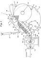
- Fig. 1 is a schematic configuration diagram of a carousel reel facility according to one embodiment of the present invention.
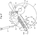
- Fig. 2 is a diagram for explaining a take-up operation.
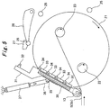
- Fig. 3 is a diagram for explaining a take-up operation subsequent to Fig. 2 .
- Fig. 4 is a diagram for explaining a take-up operation subsequent to Fig. 3 .
- Fig. 5 is a diagram for explaining a take-up operation subsequent to Fig. 4 .
- the carousel reel facility 1 shown in Fig. 1 is, for example, provided on a delivery side of a continuous tandem rolling mill including multiple rolling mill stands, in an unillustrated cold rolling mill line for manufacturing a cold-rolled strip (hereinafter, referred to as strip S).
- the strip S is formed as follows. Preceding strip Sf and following strip Sb (see Figs. 2 to 5 ) which are hot milled and coiled are unwound on the entry side of the continuous tandem rolling mill. Then, a trailing edge of the preceding strip Sf and a leading edge of the following strip Sb are connected. The above processing is repeated. Thus formed strip S is continuously fed to the continuous tandem rolling mill.
- a pair of upper and lower entry-side rollers 11a, 11b is rotatably supported on the entry side of the carousel reel facility 1. These entry-side rollers 11a, 11b are disposed facing each other to hold the transported strip S in between.
- a pair of upper and lower drum shears 12a, 12b is rotatably supported downstream of the entry-side rollers 11a, 11b. These drum shears 12a, 12b are disposed facing each other to hold the strip S transported from the entry-side rollers 11a, 11b in between.
- Cutting blades 121a, 121b are provided on the circumferential portions of the drum shears 12a, 12b, respectively, and are arranged to face each other when the drum shears are rotated. In other words, when the drum shears 12a, 12b make one revolution synchronously with the transport speed of the strip S and synchronously with each other in opposite directions, the protruding cutting blades 121a, 121b cut the strip S at a predetermined position.
- a deflector roller 13 is rotatably supported downstream of the drum shears 12a, 12b.
- the deflector roller 13 changes the transport direction of the strip S by winding the strip S thereon.
- Guide plates 14, 15 are provided below the deflector roller 13.
- the guide plate 14 extends in the transport direction of the strip S and is fixed.
- the guide plate 15, which will be described in detail later, is supported to be moveable between a guide position for guiding the strip S and a retracted position where the guide 15 is retracted from the guide position. Note that the guide plate 15 shown in Fig. 1 is disposed at the guide position.
- a disk shaped carousel reel 21 is provided on a delivery side of the carousel reel facility 1, and is rotationally driven about a substantially-horizontal axis thereof.
- a first take-up drum 22 and a second take-up drum 23 are provided on a front surface of the carousel reel 21, and are supported in such a manner as to be rotatable about substantially-horizontal axes thereof, respectively.
- the first take-up drum 22 and the second take-up drum 23 are arranged to be symmetrical with respect to the rotation axis of the carousel reel 21.
- the first take-up drum 22 takes up the cut preceding strip Sf
- the second take-up drum 23 takes up the cut following strip Sb.
- the first take-up drum 22 is disposed at a take-up start position on a reel upstream side
- the second take-up drum 23 is disposed at a take-up completion position on a reel downstream side.
- the take-up positions of the first take-up drum 22 and the second take-up drum 23 can be switched by revolving the carousel reel 21 180° clockwise.
- the take-up start position is set to be lower than the take-up completion position, and also the take-up drum 22, 23 disposed at the take-up start position is disposed at substantially the same height as the deflector roller 13. In other words, the take-up start position is set to be substantially the same height as the pass line of the strip S transported from the entry side of the carousel reel facility 1.
- a belt wrapper 24 is attachable and detachable to the first take-up drum 22 or the second take-up drum 23 disposed at the take-up start position.
- the belt wrapper 24 has a configuration in which a pressing belt is wound around multiple rollers.
- the belt wrapper 24 is wound around a circumferential surface of the take-up drum 22, 23, thereby assisting the leading edge of the cut strip Sf or Sb to be wrapped around the circumferential surface of the take-up drum 22, 23.
- multiple rotatable snubber rollers 25 are attachable and detachable to the first take-up drum 22 or the second take-up drum 23 disposed at the take-up completion position.
- the snubber rollers 25 are swingably supported, and come into contact with the circumferential surface of the strip Sf or Sb taken up by the take-up drum 22, 23, while following an increase in the coil diameter of the strip.
- the snubber rollers 25 thus press the strip Sf or Sb taken up in a coil shape so that the strip does not spring back.
- the snubber rollers 25 swing outward in the coil diameter direction while pressing against the circumferential surface of the strip S.
- the snubber roller (pressing means) 25 disposed at the highest position is rotatably supported by a tip of a swing arm 26.
- the swing arm 26 is swingably supported at its base end.
- a receiving pad 27 is provided at the tip of the swing arm 26 in such a manner as not to interfere with the rotation of the snubber roller 25.
- a base end of a guide frame 31 is swingably supported by a rotation shaft of the deflector roller 13.
- a guide roller 32 is rotatably supported by a tip of the guide frame 31.
- the guide roller 32 is disposed to face an upper surface of the receiving pad 27.
- magnets 33 and support rollers 34 are alternately provided on a bottom surface of the guide frame 31 from the base end to the tip end thereof.
- the support rollers 34 are disposed so that circumferential surfaces thereof may protrude from attracting surfaces of the magnets 33.
- a link member 35 is provided on an upper surface of the guide frame 31.
- One end of a link bar 36 is swingably supported by the link member 35.
- a rod 37a of an elevating/lowering cylinder 37 is swingably supported by the other end of the link bar 36. Further, the base end of the elevating/lowering cylinder 37 is also swingably supported.
- the guide frame 31, the guider roller 32, the magnets 33, and the support rollers 34 constitute guiding means, and that the link member 35, the link bar 36, and the elevating/lowering cylinder 37 constitute swinging means and swing allowing means.
- Extension of the rod 37a of the elevating/lowering cylinder 37 brings the guide roller 32 of the guide frame 31 into contact with the receiving pad 27 of the swing arm 26.
- the guide frame 31 is swung to a guide position, and the strip S (strip Sf or Sb) to be taken up by the take-up roller 22, 23 disposed at the take-up completion position can be guided by the support rollers 34 while being attracted by the magnets 33 (see Fig. 1 ).
- the guide frame 31 When disposed at the guide position, the guide frame 31 is made to swing by the snubber roller 25 and the guide roller 32 as the coil diameter of the strip S (strip Sf or Sb) taken up by the take-up drum 22, 23 disposed at the take-up completion position increases.
- the rod 37a of the elevating/lowering cylinder 37 is maintained in the extended state. Meanwhile, the link member 35, the link bar 36, and the elevating/lowering cylinder 37 swing to operate as a link mechanism which allows the guide frame 31 to swing.
- a demagnetizing device 38 is provided in the guide frame 31 in such a manner as to face the magnets 33.
- the demagnetizing device 38 demagnetizes peripheral devices magnetized by the magnetic forces of the magnets 33 when the carousel reel facility 1 is shut down and the magnetic forces of the magnets 33 are being turned off.
- the direction of the strip S (strip Sf) cold-rolled by the continuous tandem rolling mill is changed by the deflector roller 13, and the strip Sf is then taken up by the first take-up drum 22 having moved to the take-up completion position.
- the snubber rollers 25 are in contact with the circumferential surface of the preceding strip Sf taken up by the first take-up drum 22.
- the snubber rollers 25 thus press the preceding strip Sf so that the strip does not spring back.
- the rod 37a of the elevating/lowering cylinder 37 is extended to bring the guide roller 32 in contact with the receiving pad 27, so that the guide frame 31 is disposed at the guide position. Accordingly, the preceding strip Sf is attracted to the magnets 33, and comes into contact with the support rollers 34. As a result, the preceding strip Sf is stably guided to the first take-up drum 22 by the rotation of the support rollers 34 without fluttering or springing back.
- the second take-up drum 23 having moved to the take-up start position is in a stand-by as a substitute while being rotationally driven.
- the belt wrapper 24 is wound around the circumferential surface of the second take-up drum 23.
- the snubber rollers 25 swing outward in the coil diameter direction of the preceding strip Sf as the coil diameter of the preceding strip Sf taken up by the first take-up drum 22 increases.
- the swing arm 26 also swings.
- the guide roller 32 rolls on the receiving pad 27 of the swing arm 26, and consequently the guide frame 31 also swings.
- the snubber rollers 25 swing along with the increase in the coil diameter of the preceding strip Sf, and the link member 35, the link bar 36, and the elevating/lowering cylinder 37 in the extended state performs the link operation.
- This causes the guide frame 31 to swing at substantially the same angle as a take-up angel of the preceding strip S in accordance with the swinging of the snubber rollers 25.
- the attracting surfaces of the magnets 33 are always parallel to the surface of the preceding strip Sf.
- efficient attracting is performed, and the surface of the preceding strip Sf is securely in contact with the circumferential surfaces of the support rollers 34 to stably guide the preceding strip Sf.
- the guide frame 31 since there is no need to operate the elevating/lowering cylinder 37, the guide frame 31 operates in accordance with the snubber rollers 25 through the guide roller 32 without any response delay to the swinging of the snubber rollers 25.
- the cutting blades 121a, 121b protrude from the drum shears 12a, 12b rotationally driven, thereby cutting the connecting portion between the preceding strip Sf and the following strip Sb.
- the preceding strip Sf is attracted to the magnets 33 of the guide frame 31 before being cut and is therefore stably guided, the trailing edge of the preceding strip Sf is stably guided along the support rollers 34 to the first take-up drum 22 without fluttering or springing back even after the preceding strip Sf loses its tension by being cut.
- a coil of the preceding strip Sf taken up by the first take-up drum 22 is pulled out by an unillustrated coil pulling-out device.
- the rod 37a of the elevating/lowering cylinder 37 contracts to move the guide frame 31 to the retracted position, and the snubber rollers 25 are also retracted outward from the carousel reel 21.
- the attraction of the lowermost (base end side of the guide frame 31) magnet 33 is turned off, and therefore the cut following strip Sb travels on the guide plate 15 having moved to the guide position and is taken up by the second take-up drum 23 disposed at the take-up start position.
- the belt wrapper 24 is wound around the circumferential surface of the second take-up drum 23, the leading edge of the cut following strip Sb is securely wound around the circumferential surface of the second take-up drum 23.
- the guide plate 15 is moved to the retracted position, and the belt wrapper 24 is released from the second take-up drum 23 and retracted downward. Then, the carousel reel 21 is revolved 180°. Thus, the second take-up drum 23 is moved to the take-up completion position while taking up the following strip Sb. On the other hand, the first take-up drum 22 is moved to the take-up start position to be in the stand-by state. Thereafter, similar take-up operations are repeated in sequence.
- the carousel reel facility of the present invention achieves the following.
- the tip of the guide frame 31 is caused to be attachably and detachably in contact with the snubber roller 25 which is pressing against the circumferential surface of the strip S taken up at the take-up completion position, while following an increase in the coil diameter.
- This allows the guide frame 31 to swing in accordance with the coil diameter following operation of the snubber rollers 25.
- the strip S is attracted to the magnets 33 regardless of its coil diameter, and comes into contact with the support rollers 34. Accordingly, even when the strip S is cut and is released from tension, the trailing edge thereof is stably guided to the take-up drum 22, 23 disposed at the take-up completion position.
- the rod 37a of the elevating/lowering cylinder 37 is maintained at the extended state, and the link member 35, the link bar 36, and the elevating/lowering cylinder 37 operate as the link mechanism.
- This allows the guide frame 31 to swing at substantially the same angle as the take-up angle of the strip S.
- the strip S is effectively attracted to the magnets 33, and is stably guided by the support rollers 34.
- the guide frame 31 can operate in accordance with the coil diameter following operation of the snubber rollers 25 without any response delay.
- the transport speed of the strip S when the cutting is performed can be set to 250 m/min to 350 m/min. This not only increases the productivity, but also eliminates the risk of adversely affecting a plate-shape control of the strips S during rolling. As a result, the strip S can be rolled highly accurately, and the quality thereof can be improved.
- the carousel reel facility when the transport speed of the strip S is 250 m/min to 300 m/min during the cutting, the trailing edge of the strip S can be guided only by the support rollers 34 without the strip S being attracted to the magnets 33.
- the carousel reel facility is configured to perform the attraction of the magnets 33 only when the transport speed of the strip S is 300 m/min to 350 m/min during the cutting.
- the present invention is applicable to a highly productive carousel reel facility having excellent yield.
Landscapes
- Engineering & Computer Science (AREA)
- Mechanical Engineering (AREA)
- Winding, Rewinding, Material Storage Devices (AREA)
Claims (2)
- Rundlaufaufrollanlage (1), in der
eine scheibenförmige drehbare Rundlaufrolle (21) mit zwei rotierbaren Aufnahmetrommeln (22, 23) versehen ist, die jeweils an bezüglich einer Rotationsachse der Rundlaufrolle (21) zueinander symmetrischen Positionen angeordnet sind,
eine der Aufnahmetrommeln (22), die an einer stromaufwärtigen Seite angeordnet ist, einen vorhergehenden Streifen (S, Sf) aufzunehmen beginnt,
die Rundlaufrolle (21) während des Aufnehmens gedreht wird, um die eine Aufnahmetrommel (22) auf eine stromabwärtige Seite und die andere Aufnahmetrommel (3) auf die stromaufwärtige Seite zu bewegen, und
in diesem Zustand eine nachlaufende Kante des vorhergehenden Streifens (S, Sf) geschnitten wird und eine führende Kante eines folgenden Streifens (S, Sb) von der anderen Aufnahmetrommel aufgenommen wird, wobei die Rundlaufaufrollanlage (1) umfasst:eine Ablenkrolle (13), die auf einer Eingangsseite der Rundlaufrolle (21) an einer fast so hohen Position wie die auf der stromaufwärtigen Seite angeordnete Aufnahmetrommel (22, 23) vorgesehen ist, wobei die Ablenkrolle (13) den geförderten Streifen (S, Sf, Sb) zu irgendeiner der auf der stromaufwärtigen und der stromabwärtigen Seite angeordneten Aufnahmetrommeln (22, 23) führt;eine Dämpfungsrolle (25), die von einer Spitze eines schwenkbar gehaltenen Schwenkarms (26) rotierbar gehalten wird und gegen eine Umfangsoberfläche des Streifens (S, Sf, Sb), der von der auf der stromabwärtigen Seite angeordneten Aufnahmetrommel (22, 23) aufgenommen wird, drückt, während sie einer Erhöhung in einem Spuldurchmesser des Streifens (S, Sf, Sb) folgt, und damit das Flattern der nachfolgenden Kante des geschnittenen Streifens (S, Sf, Sb) verhindert;eine Führungseinrichtung (31, 32, 33, 34), die einen Führungsrahmen enthält, der an seinem Basisende durch die Rotationswelle der Ablenkrolle (13) schwenkbar gehalten wird, sodass die Führungseinrichtung (31, 32, 33, 34) um die Rotationswelle der Ablenkrolle (13) schwenkbar ist, wobei die Führungseinrichtung die nachfolgende Kante des geschnittenen Streifens (S, Sf, Sb) zu der auf der stromabwärtigen Seite angeordneten Aufnahmetrommel (22, 23) führt, während eine Spitze der Führungseinrichtung (31, 32, 33, 34) gemäß einem Spuldurchmesserfolgevorgang der Dämpfungsrolle (25) arbeiten gelassen wird;eine Schwenkeinrichtung (35, 36, 37), die die Führungseinrichtung schwingen lässt, sodass die Führungseinrichtung (31, 32, 33, 34) nicht die durch die Drehung der Rundlaufrollen (21) bewegten Aufnahmetrommeln (22, 23) stört; undeine Schwingmöglichkeitseinrichtung (35, 36, 37), die der Führungseinrichtung (31, 32, 33, 34) das Schwingen gemäß dem Spuldurchmesserfolgevorgang der Dämpfungsrolle (25) ohne Betreiben der Schwenkeinrichtung (35, 36, 37) ermöglicht;gekennzeichnet dadurch, dassein Empfangsblock (27) am spitzen Ende des Schwenkarms (26) so vorgesehen ist, dass er die Rotation der Dämpfungsrolle (25) nicht stört, unddie Führungseinrichtung, (31, 32, 33, 34) ferner eine Führungsrolle (32) enthält, die von einem spitzen Ende des Führungsrahmens (31) rotierbar gehalten wird, wobei die Führungsrolle an und von einer oberen Oberfläche des Empfangsblocks (27) anbringbar und abnehmbar ist. - Rundlaufaufrollanlage nach Anspruch 1, wobei die Führungseinrichtung (31, 32, 33, 34) dazu ausgelegt ist, eine Fördergeschwindigkeit des Streifens während des Schneidens auf 250 m/min oder höher einzustellen.
Applications Claiming Priority (2)
| Application Number | Priority Date | Filing Date | Title |
|---|---|---|---|
| JP2008107445A JP5313542B2 (ja) | 2008-04-17 | 2008-04-17 | カローゼルリール設備 |
| PCT/JP2009/057231 WO2009128380A1 (ja) | 2008-04-17 | 2009-04-08 | カローゼルリール設備 |
Publications (3)
| Publication Number | Publication Date |
|---|---|
| EP2277640A1 EP2277640A1 (de) | 2011-01-26 |
| EP2277640A4 EP2277640A4 (de) | 2014-12-17 |
| EP2277640B1 true EP2277640B1 (de) | 2017-02-01 |
Family
ID=41199077
Family Applications (1)
| Application Number | Title | Priority Date | Filing Date |
|---|---|---|---|
| EP09732948.6A Active EP2277640B1 (de) | 2008-04-17 | 2009-04-08 | Rundläuferrollenlanlage |
Country Status (5)
| Country | Link |
|---|---|
| EP (1) | EP2277640B1 (de) |
| JP (1) | JP5313542B2 (de) |
| CN (1) | CN102006946B (de) |
| BR (1) | BRPI0910731A2 (de) |
| WO (1) | WO2009128380A1 (de) |
Families Citing this family (11)
| Publication number | Priority date | Publication date | Assignee | Title |
|---|---|---|---|---|
| IT1397452B1 (it) * | 2009-12-30 | 2013-01-10 | Danieli E C Ohg S P A | Dispositivo e procedimento per avvolgere/svolgere un prodotto metallico in una linea di laminazione |
| CN102527769B (zh) * | 2010-12-22 | 2014-03-12 | 中国二十冶集团有限公司 | 卡罗塞尔卷取机偏移倾斜安装方法 |
| KR101207699B1 (ko) | 2010-12-28 | 2012-12-03 | 주식회사 포스코 | 스트립 권취 유도 장치 |
| US8824951B2 (en) | 2011-11-30 | 2014-09-02 | Ricoh Company, Ltd. | Toner conveyor, process cartridge, and image forming apparatus |
| KR101368259B1 (ko) | 2012-04-26 | 2014-03-12 | 현대제철 주식회사 | 소재 권취장치 |
| CN102836899B (zh) * | 2012-09-25 | 2014-07-30 | 鞍钢股份有限公司 | 一种将翘头带钢引入卷筒钳口的方法 |
| CN103691742B (zh) * | 2013-12-03 | 2015-11-18 | 内蒙古包钢钢联股份有限公司 | 改善卡伦赛卷取机转盘旋转过程张力波动的方法 |
| CN112077111A (zh) * | 2020-07-20 | 2020-12-15 | 赵海荣 | 一种废弃轨道回收处理装置 |
| CN112705585B (zh) * | 2020-12-25 | 2022-11-22 | 贵州航天南海科技有限责任公司 | 一种梅花收线装置 |
| CN113148760A (zh) * | 2021-04-30 | 2021-07-23 | 非凡电缆集团有限公司 | 一种电缆双收装置的操作方法 |
| EP4389313A1 (de) * | 2022-12-22 | 2024-06-26 | Primetals Technologies Austria GmbH | Haspelsystem für eine giess-walz-verbundanlage und verfahren zum betrieb des haspelsystems |
Family Cites Families (10)
| Publication number | Priority date | Publication date | Assignee | Title |
|---|---|---|---|---|
| DE2037869A1 (en) * | 1970-07-30 | 1972-02-03 | Siemag Siegener Masch Bau | Coiler for hot wide strip - using pressure rollers and guides |
| JPS5643807B2 (de) * | 1973-10-29 | 1981-10-15 | ||
| JPS5851817U (ja) * | 1981-09-30 | 1983-04-08 | 株式会社日立製作所 | ストリツプの巻取り機用案内装置 |
| JPH078381B2 (ja) | 1986-12-05 | 1995-02-01 | 株式会社日立製作所 | 後端ストリツプ巻取用案内装置 |
| JPH07106384B2 (ja) * | 1987-01-28 | 1995-11-15 | 株式会社日立製作所 | ストリツプ尾端巻取案内装置 |
| JP2904675B2 (ja) * | 1993-05-14 | 1999-06-14 | 新日本製鐵株式会社 | 鋼板巻き取りガイド装置 |
| CA2296551A1 (en) * | 1997-07-15 | 1999-01-28 | Danieli & C. Officine Meccaniche S.P.A. | Coiling machine for hot rolled stock such as strip or sheet and relative coiling method |
| JP2000301234A (ja) * | 1999-04-13 | 2000-10-31 | Hitachi Ltd | 巻取り設備及び巻取り方法 |
| JP3845352B2 (ja) * | 2002-09-26 | 2006-11-15 | 新日本製鐵株式会社 | 金属帯の蛇行矯正巻取方法および金属帯の蛇行矯正巻取装置 |
| CN2714190Y (zh) * | 2003-04-23 | 2005-08-03 | 攀枝花新钢钒股份有限公司热轧板厂 | 钢卷卧式取样装置 |
-
2008
- 2008-04-17 JP JP2008107445A patent/JP5313542B2/ja active Active
-
2009
- 2009-04-08 BR BRPI0910731A patent/BRPI0910731A2/pt not_active Application Discontinuation
- 2009-04-08 CN CN200980113210.9A patent/CN102006946B/zh active Active
- 2009-04-08 WO PCT/JP2009/057231 patent/WO2009128380A1/ja not_active Ceased
- 2009-04-08 EP EP09732948.6A patent/EP2277640B1/de active Active
Non-Patent Citations (1)
| Title |
|---|
| None * |
Also Published As
| Publication number | Publication date |
|---|---|
| JP2009255129A (ja) | 2009-11-05 |
| CN102006946A (zh) | 2011-04-06 |
| EP2277640A4 (de) | 2014-12-17 |
| JP5313542B2 (ja) | 2013-10-09 |
| CN102006946B (zh) | 2012-12-26 |
| WO2009128380A1 (ja) | 2009-10-22 |
| EP2277640A1 (de) | 2011-01-26 |
| BRPI0910731A2 (pt) | 2015-09-29 |
Similar Documents
| Publication | Publication Date | Title |
|---|---|---|
| EP2277640B1 (de) | Rundläuferrollenlanlage | |
| JP5767246B2 (ja) | 巻取/巻戻装置および圧延ラインにおける金属製品の巻取/巻戻方法 | |
| TWI593949B (zh) | 金屬帶取樣的裝置與方法 | |
| AU732328B2 (en) | Shearing and coiling assembly for hot rolled stock | |
| CN101247915B (zh) | 用于采样的装置和方法 | |
| EP1015147B1 (de) | Hochgeschwindigkeitsstreifenübertragung in einer streifen-verarbeitungsanwendung | |
| JPH11342402A (ja) | 冷間圧延設備 | |
| JP5893716B1 (ja) | セパレーター装置、コイル製品の製造装置及び製造方法 | |
| CN217807742U (zh) | 一种转塔收卷扶料机构与转塔收卷装置 | |
| JP2005510362A (ja) | 圧延作業の終期においてストリップ処理設備から走行している残余ストリップから巻取り可能な残余コイルのためのグリッパ | |
| JP2996844B2 (ja) | 金属ストリップ連続処理ラインの間紙挿入装置 | |
| JP2862125B2 (ja) | 巻取り機のコイル押え装置 | |
| EP1753558B1 (de) | Verbesserte wickelmaschine für gewalzten oder gezogenen draht/stab | |
| CN120696260B (zh) | 一种适用于多种尺寸的彩装铝卷开卷机 | |
| CN112533709A (zh) | 卷轴装置以及具备其的轧制设备及轧制方法 | |
| JPH10263698A (ja) | ストリップ切断方法 |
Legal Events
| Date | Code | Title | Description |
|---|---|---|---|
| PUAI | Public reference made under article 153(3) epc to a published international application that has entered the european phase |
Free format text: ORIGINAL CODE: 0009012 |
|
| 17P | Request for examination filed |
Effective date: 20101115 |
|
| AK | Designated contracting states |
Kind code of ref document: A1 Designated state(s): AT BE BG CH CY CZ DE DK EE ES FI FR GB GR HR HU IE IS IT LI LT LU LV MC MK MT NL NO PL PT RO SE SI SK TR |
|
| AX | Request for extension of the european patent |
Extension state: AL BA RS |
|
| DAX | Request for extension of the european patent (deleted) | ||
| A4 | Supplementary search report drawn up and despatched |
Effective date: 20141113 |
|
| RIC1 | Information provided on ipc code assigned before grant |
Ipc: B21C 47/34 20060101ALI20141107BHEP Ipc: B21C 47/00 20060101ALI20141107BHEP Ipc: B21C 47/02 20060101AFI20141107BHEP |
|
| RAP1 | Party data changed (applicant data changed or rights of an application transferred) |
Owner name: PRIMETALS TECHNOLOGIES JAPAN, LTD. |
|
| GRAP | Despatch of communication of intention to grant a patent |
Free format text: ORIGINAL CODE: EPIDOSNIGR1 |
|
| INTG | Intention to grant announced |
Effective date: 20160725 |
|
| STAA | Information on the status of an ep patent application or granted ep patent |
Free format text: STATUS: GRANT OF PATENT IS INTENDED |
|
| GRAJ | Information related to disapproval of communication of intention to grant by the applicant or resumption of examination proceedings by the epo deleted |
Free format text: ORIGINAL CODE: EPIDOSDIGR1 |
|
| STAA | Information on the status of an ep patent application or granted ep patent |
Free format text: STATUS: REQUEST FOR EXAMINATION WAS MADE |
|
| GRAR | Information related to intention to grant a patent recorded |
Free format text: ORIGINAL CODE: EPIDOSNIGR71 |
|
| GRAS | Grant fee paid |
Free format text: ORIGINAL CODE: EPIDOSNIGR3 |
|
| STAA | Information on the status of an ep patent application or granted ep patent |
Free format text: STATUS: GRANT OF PATENT IS INTENDED |
|
| GRAA | (expected) grant |
Free format text: ORIGINAL CODE: 0009210 |
|
| STAA | Information on the status of an ep patent application or granted ep patent |
Free format text: STATUS: THE PATENT HAS BEEN GRANTED |
|
| INTC | Intention to grant announced (deleted) | ||
| INTG | Intention to grant announced |
Effective date: 20161222 |
|
| AK | Designated contracting states |
Kind code of ref document: B1 Designated state(s): AT BE BG CH CY CZ DE DK EE ES FI FR GB GR HR HU IE IS IT LI LT LU LV MC MK MT NL NO PL PT RO SE SI SK TR |
|
| REG | Reference to a national code |
Ref country code: GB Ref legal event code: FG4D |
|
| REG | Reference to a national code |
Ref country code: CH Ref legal event code: EP Ref country code: AT Ref legal event code: REF Ref document number: 865111 Country of ref document: AT Kind code of ref document: T Effective date: 20170215 |
|
| REG | Reference to a national code |
Ref country code: IE Ref legal event code: FG4D |
|
| REG | Reference to a national code |
Ref country code: DE Ref legal event code: R096 Ref document number: 602009044057 Country of ref document: DE |
|
| REG | Reference to a national code |
Ref country code: NL Ref legal event code: MP Effective date: 20170201 |
|
| REG | Reference to a national code |
Ref country code: LT Ref legal event code: MG4D |
|
| PG25 | Lapsed in a contracting state [announced via postgrant information from national office to epo] |
Ref country code: LT Free format text: LAPSE BECAUSE OF FAILURE TO SUBMIT A TRANSLATION OF THE DESCRIPTION OR TO PAY THE FEE WITHIN THE PRESCRIBED TIME-LIMIT Effective date: 20170201 Ref country code: IS Free format text: LAPSE BECAUSE OF FAILURE TO SUBMIT A TRANSLATION OF THE DESCRIPTION OR TO PAY THE FEE WITHIN THE PRESCRIBED TIME-LIMIT Effective date: 20170601 Ref country code: GR Free format text: LAPSE BECAUSE OF FAILURE TO SUBMIT A TRANSLATION OF THE DESCRIPTION OR TO PAY THE FEE WITHIN THE PRESCRIBED TIME-LIMIT Effective date: 20170502 Ref country code: HR Free format text: LAPSE BECAUSE OF FAILURE TO SUBMIT A TRANSLATION OF THE DESCRIPTION OR TO PAY THE FEE WITHIN THE PRESCRIBED TIME-LIMIT Effective date: 20170201 Ref country code: FI Free format text: LAPSE BECAUSE OF FAILURE TO SUBMIT A TRANSLATION OF THE DESCRIPTION OR TO PAY THE FEE WITHIN THE PRESCRIBED TIME-LIMIT Effective date: 20170201 Ref country code: NO Free format text: LAPSE BECAUSE OF FAILURE TO SUBMIT A TRANSLATION OF THE DESCRIPTION OR TO PAY THE FEE WITHIN THE PRESCRIBED TIME-LIMIT Effective date: 20170501 |
|
| PG25 | Lapsed in a contracting state [announced via postgrant information from national office to epo] |
Ref country code: NL Free format text: LAPSE BECAUSE OF FAILURE TO SUBMIT A TRANSLATION OF THE DESCRIPTION OR TO PAY THE FEE WITHIN THE PRESCRIBED TIME-LIMIT Effective date: 20170201 Ref country code: PL Free format text: LAPSE BECAUSE OF FAILURE TO SUBMIT A TRANSLATION OF THE DESCRIPTION OR TO PAY THE FEE WITHIN THE PRESCRIBED TIME-LIMIT Effective date: 20170201 Ref country code: LV Free format text: LAPSE BECAUSE OF FAILURE TO SUBMIT A TRANSLATION OF THE DESCRIPTION OR TO PAY THE FEE WITHIN THE PRESCRIBED TIME-LIMIT Effective date: 20170201 Ref country code: BG Free format text: LAPSE BECAUSE OF FAILURE TO SUBMIT A TRANSLATION OF THE DESCRIPTION OR TO PAY THE FEE WITHIN THE PRESCRIBED TIME-LIMIT Effective date: 20170501 Ref country code: ES Free format text: LAPSE BECAUSE OF FAILURE TO SUBMIT A TRANSLATION OF THE DESCRIPTION OR TO PAY THE FEE WITHIN THE PRESCRIBED TIME-LIMIT Effective date: 20170201 Ref country code: SE Free format text: LAPSE BECAUSE OF FAILURE TO SUBMIT A TRANSLATION OF THE DESCRIPTION OR TO PAY THE FEE WITHIN THE PRESCRIBED TIME-LIMIT Effective date: 20170201 Ref country code: PT Free format text: LAPSE BECAUSE OF FAILURE TO SUBMIT A TRANSLATION OF THE DESCRIPTION OR TO PAY THE FEE WITHIN THE PRESCRIBED TIME-LIMIT Effective date: 20170601 |
|
| PG25 | Lapsed in a contracting state [announced via postgrant information from national office to epo] |
Ref country code: RO Free format text: LAPSE BECAUSE OF FAILURE TO SUBMIT A TRANSLATION OF THE DESCRIPTION OR TO PAY THE FEE WITHIN THE PRESCRIBED TIME-LIMIT Effective date: 20170201 Ref country code: EE Free format text: LAPSE BECAUSE OF FAILURE TO SUBMIT A TRANSLATION OF THE DESCRIPTION OR TO PAY THE FEE WITHIN THE PRESCRIBED TIME-LIMIT Effective date: 20170201 Ref country code: SK Free format text: LAPSE BECAUSE OF FAILURE TO SUBMIT A TRANSLATION OF THE DESCRIPTION OR TO PAY THE FEE WITHIN THE PRESCRIBED TIME-LIMIT Effective date: 20170201 Ref country code: CZ Free format text: LAPSE BECAUSE OF FAILURE TO SUBMIT A TRANSLATION OF THE DESCRIPTION OR TO PAY THE FEE WITHIN THE PRESCRIBED TIME-LIMIT Effective date: 20170201 |
|
| REG | Reference to a national code |
Ref country code: DE Ref legal event code: R097 Ref document number: 602009044057 Country of ref document: DE |
|
| PG25 | Lapsed in a contracting state [announced via postgrant information from national office to epo] |
Ref country code: DK Free format text: LAPSE BECAUSE OF FAILURE TO SUBMIT A TRANSLATION OF THE DESCRIPTION OR TO PAY THE FEE WITHIN THE PRESCRIBED TIME-LIMIT Effective date: 20170201 |
|
| REG | Reference to a national code |
Ref country code: CH Ref legal event code: PL |
|
| PLBE | No opposition filed within time limit |
Free format text: ORIGINAL CODE: 0009261 |
|
| STAA | Information on the status of an ep patent application or granted ep patent |
Free format text: STATUS: NO OPPOSITION FILED WITHIN TIME LIMIT |
|
| 26N | No opposition filed |
Effective date: 20171103 |
|
| GBPC | Gb: european patent ceased through non-payment of renewal fee |
Effective date: 20170501 |
|
| REG | Reference to a national code |
Ref country code: IE Ref legal event code: MM4A |
|
| REG | Reference to a national code |
Ref country code: FR Ref legal event code: ST Effective date: 20171229 |
|
| PG25 | Lapsed in a contracting state [announced via postgrant information from national office to epo] |
Ref country code: FR Free format text: LAPSE BECAUSE OF NON-PAYMENT OF DUE FEES Effective date: 20170502 Ref country code: MC Free format text: LAPSE BECAUSE OF FAILURE TO SUBMIT A TRANSLATION OF THE DESCRIPTION OR TO PAY THE FEE WITHIN THE PRESCRIBED TIME-LIMIT Effective date: 20170201 |
|
| PG25 | Lapsed in a contracting state [announced via postgrant information from national office to epo] |
Ref country code: LI Free format text: LAPSE BECAUSE OF NON-PAYMENT OF DUE FEES Effective date: 20170430 Ref country code: LU Free format text: LAPSE BECAUSE OF NON-PAYMENT OF DUE FEES Effective date: 20170408 Ref country code: CH Free format text: LAPSE BECAUSE OF NON-PAYMENT OF DUE FEES Effective date: 20170430 Ref country code: SI Free format text: LAPSE BECAUSE OF FAILURE TO SUBMIT A TRANSLATION OF THE DESCRIPTION OR TO PAY THE FEE WITHIN THE PRESCRIBED TIME-LIMIT Effective date: 20170201 |
|
| REG | Reference to a national code |
Ref country code: BE Ref legal event code: MM Effective date: 20170430 |
|
| PG25 | Lapsed in a contracting state [announced via postgrant information from national office to epo] |
Ref country code: IE Free format text: LAPSE BECAUSE OF NON-PAYMENT OF DUE FEES Effective date: 20170408 Ref country code: GB Free format text: LAPSE BECAUSE OF NON-PAYMENT OF DUE FEES Effective date: 20170501 |
|
| PG25 | Lapsed in a contracting state [announced via postgrant information from national office to epo] |
Ref country code: BE Free format text: LAPSE BECAUSE OF NON-PAYMENT OF DUE FEES Effective date: 20170430 |
|
| PG25 | Lapsed in a contracting state [announced via postgrant information from national office to epo] |
Ref country code: MT Free format text: LAPSE BECAUSE OF NON-PAYMENT OF DUE FEES Effective date: 20170408 |
|
| PG25 | Lapsed in a contracting state [announced via postgrant information from national office to epo] |
Ref country code: HU Free format text: LAPSE BECAUSE OF FAILURE TO SUBMIT A TRANSLATION OF THE DESCRIPTION OR TO PAY THE FEE WITHIN THE PRESCRIBED TIME-LIMIT; INVALID AB INITIO Effective date: 20090408 |
|
| REG | Reference to a national code |
Ref country code: AT Ref legal event code: UEP Ref document number: 865111 Country of ref document: AT Kind code of ref document: T Effective date: 20170201 |
|
| PG25 | Lapsed in a contracting state [announced via postgrant information from national office to epo] |
Ref country code: CY Free format text: LAPSE BECAUSE OF NON-PAYMENT OF DUE FEES Effective date: 20170201 |
|
| PG25 | Lapsed in a contracting state [announced via postgrant information from national office to epo] |
Ref country code: MK Free format text: LAPSE BECAUSE OF FAILURE TO SUBMIT A TRANSLATION OF THE DESCRIPTION OR TO PAY THE FEE WITHIN THE PRESCRIBED TIME-LIMIT Effective date: 20170201 |
|
| PG25 | Lapsed in a contracting state [announced via postgrant information from national office to epo] |
Ref country code: TR Free format text: LAPSE BECAUSE OF FAILURE TO SUBMIT A TRANSLATION OF THE DESCRIPTION OR TO PAY THE FEE WITHIN THE PRESCRIBED TIME-LIMIT Effective date: 20170201 |
|
| PGFP | Annual fee paid to national office [announced via postgrant information from national office to epo] |
Ref country code: IT Payment date: 20250320 Year of fee payment: 17 |
|
| PGFP | Annual fee paid to national office [announced via postgrant information from national office to epo] |
Ref country code: DE Payment date: 20250305 Year of fee payment: 17 |
|
| PGFP | Annual fee paid to national office [announced via postgrant information from national office to epo] |
Ref country code: AT Payment date: 20250325 Year of fee payment: 17 |