EP2275389B1 - Heizvorrichtung und herstellungsverfahren dafür - Google Patents
Heizvorrichtung und herstellungsverfahren dafür Download PDFInfo
- Publication number
- EP2275389B1 EP2275389B1 EP09721668.3A EP09721668A EP2275389B1 EP 2275389 B1 EP2275389 B1 EP 2275389B1 EP 09721668 A EP09721668 A EP 09721668A EP 2275389 B1 EP2275389 B1 EP 2275389B1
- Authority
- EP
- European Patent Office
- Prior art keywords
- pattern
- heating element
- heating
- conductive
- element according
- Prior art date
- Legal status (The legal status is an assumption and is not a legal conclusion. Google has not performed a legal analysis and makes no representation as to the accuracy of the status listed.)
- Active
Links
- 238000004519 manufacturing process Methods 0.000 title claims description 19
- 238000010438 heat treatment Methods 0.000 claims description 171
- 238000000034 method Methods 0.000 claims description 58
- 239000011521 glass Substances 0.000 claims description 32
- 229920005989 resin Polymers 0.000 claims description 32
- 239000011347 resin Substances 0.000 claims description 32
- 238000007639 printing Methods 0.000 claims description 22
- 239000000463 material Substances 0.000 claims description 20
- 239000000126 substance Substances 0.000 claims description 20
- 238000007645 offset printing Methods 0.000 claims description 10
- 238000005245 sintering Methods 0.000 claims description 8
- 239000000758 substrate Substances 0.000 claims description 8
- 239000004033 plastic Substances 0.000 claims description 4
- 229920003023 plastic Polymers 0.000 claims description 4
- 229910003460 diamond Inorganic materials 0.000 claims description 2
- 239000010432 diamond Substances 0.000 claims description 2
- 238000002834 transmittance Methods 0.000 claims 3
- 230000001788 irregular Effects 0.000 claims 2
- 239000010408 film Substances 0.000 description 28
- BQCADISMDOOEFD-UHFFFAOYSA-N Silver Chemical compound [Ag] BQCADISMDOOEFD-UHFFFAOYSA-N 0.000 description 9
- 229910052709 silver Inorganic materials 0.000 description 9
- 239000004332 silver Substances 0.000 description 9
- 239000011230 binding agent Substances 0.000 description 7
- 239000002184 metal Substances 0.000 description 6
- 229910052751 metal Inorganic materials 0.000 description 6
- 239000002904 solvent Substances 0.000 description 6
- OKTJSMMVPCPJKN-UHFFFAOYSA-N Carbon Chemical compound [C] OKTJSMMVPCPJKN-UHFFFAOYSA-N 0.000 description 4
- 229910052802 copper Inorganic materials 0.000 description 4
- 239000010949 copper Substances 0.000 description 4
- 230000035699 permeability Effects 0.000 description 4
- -1 polyethylene naphthalate Polymers 0.000 description 4
- RYGMFSIKBFXOCR-UHFFFAOYSA-N Copper Chemical compound [Cu] RYGMFSIKBFXOCR-UHFFFAOYSA-N 0.000 description 3
- 230000005540 biological transmission Effects 0.000 description 3
- 239000002041 carbon nanotube Substances 0.000 description 3
- 229910021393 carbon nanotube Inorganic materials 0.000 description 3
- 238000007598 dipping method Methods 0.000 description 3
- 238000000206 photolithography Methods 0.000 description 3
- 229920006255 plastic film Polymers 0.000 description 3
- 239000002985 plastic film Substances 0.000 description 3
- 229920001200 poly(ethylene-vinyl acetate) Polymers 0.000 description 3
- MHAJPDPJQMAIIY-UHFFFAOYSA-N Hydrogen peroxide Chemical compound OO MHAJPDPJQMAIIY-UHFFFAOYSA-N 0.000 description 2
- 239000002313 adhesive film Substances 0.000 description 2
- 230000000694 effects Effects 0.000 description 2
- 238000005530 etching Methods 0.000 description 2
- 229910052736 halogen Inorganic materials 0.000 description 2
- 238000005259 measurement Methods 0.000 description 2
- 239000000203 mixture Substances 0.000 description 2
- 230000003287 optical effect Effects 0.000 description 2
- 239000002245 particle Substances 0.000 description 2
- 229920003207 poly(ethylene-2,6-naphthalate) Polymers 0.000 description 2
- 229920002037 poly(vinyl butyral) polymer Polymers 0.000 description 2
- 229920001225 polyester resin Polymers 0.000 description 2
- 239000011112 polyethylene naphthalate Substances 0.000 description 2
- 229920000139 polyethylene terephthalate Polymers 0.000 description 2
- 239000005020 polyethylene terephthalate Substances 0.000 description 2
- 239000002952 polymeric resin Substances 0.000 description 2
- 229920000098 polyolefin Polymers 0.000 description 2
- 239000004814 polyurethane Substances 0.000 description 2
- 238000007650 screen-printing Methods 0.000 description 2
- 229920003002 synthetic resin Polymers 0.000 description 2
- 239000010409 thin film Substances 0.000 description 2
- VXQBJTKSVGFQOL-UHFFFAOYSA-N 2-(2-butoxyethoxy)ethyl acetate Chemical compound CCCCOCCOCCOC(C)=O VXQBJTKSVGFQOL-UHFFFAOYSA-N 0.000 description 1
- FPZWZCWUIYYYBU-UHFFFAOYSA-N 2-(2-ethoxyethoxy)ethyl acetate Chemical compound CCOCCOCCOC(C)=O FPZWZCWUIYYYBU-UHFFFAOYSA-N 0.000 description 1
- SVONRAPFKPVNKG-UHFFFAOYSA-N 2-ethoxyethyl acetate Chemical compound CCOCCOC(C)=O SVONRAPFKPVNKG-UHFFFAOYSA-N 0.000 description 1
- 229920002799 BoPET Polymers 0.000 description 1
- VEXZGXHMUGYJMC-UHFFFAOYSA-M Chloride anion Chemical compound [Cl-] VEXZGXHMUGYJMC-UHFFFAOYSA-M 0.000 description 1
- 206010060904 Freezing phenomenon Diseases 0.000 description 1
- GRYLNZFGIOXLOG-UHFFFAOYSA-N Nitric acid Chemical class O[N+]([O-])=O GRYLNZFGIOXLOG-UHFFFAOYSA-N 0.000 description 1
- 239000000853 adhesive Substances 0.000 description 1
- 230000001070 adhesive effect Effects 0.000 description 1
- WUOACPNHFRMFPN-UHFFFAOYSA-N alpha-terpineol Chemical compound CC1=CCC(C(C)(C)O)CC1 WUOACPNHFRMFPN-UHFFFAOYSA-N 0.000 description 1
- 230000015572 biosynthetic process Effects 0.000 description 1
- 229910052799 carbon Inorganic materials 0.000 description 1
- 239000006229 carbon black Substances 0.000 description 1
- 229920002678 cellulose Polymers 0.000 description 1
- 239000001913 cellulose Substances 0.000 description 1
- 239000012461 cellulose resin Substances 0.000 description 1
- 239000011248 coating agent Substances 0.000 description 1
- 238000000576 coating method Methods 0.000 description 1
- 239000004020 conductor Substances 0.000 description 1
- 238000010276 construction Methods 0.000 description 1
- 238000001816 cooling Methods 0.000 description 1
- JHIVVAPYMSGYDF-UHFFFAOYSA-N cyclohexanone Chemical compound O=C1CCCCC1 JHIVVAPYMSGYDF-UHFFFAOYSA-N 0.000 description 1
- SQIFACVGCPWBQZ-UHFFFAOYSA-N delta-terpineol Natural products CC(C)(O)C1CCC(=C)CC1 SQIFACVGCPWBQZ-UHFFFAOYSA-N 0.000 description 1
- 239000007772 electrode material Substances 0.000 description 1
- 238000005516 engineering process Methods 0.000 description 1
- 239000003822 epoxy resin Substances 0.000 description 1
- 239000007789 gas Substances 0.000 description 1
- 150000002367 halogens Chemical class 0.000 description 1
- AMGQUBHHOARCQH-UHFFFAOYSA-N indium;oxotin Chemical compound [In].[Sn]=O AMGQUBHHOARCQH-UHFFFAOYSA-N 0.000 description 1
- 150000002500 ions Chemical class 0.000 description 1
- 229910052742 iron Inorganic materials 0.000 description 1
- 238000009766 low-temperature sintering Methods 0.000 description 1
- 239000007769 metal material Substances 0.000 description 1
- 229910044991 metal oxide Inorganic materials 0.000 description 1
- 150000004706 metal oxides Chemical class 0.000 description 1
- 238000012986 modification Methods 0.000 description 1
- 230000004048 modification Effects 0.000 description 1
- 230000000704 physical effect Effects 0.000 description 1
- 239000000049 pigment Substances 0.000 description 1
- 229920000515 polycarbonate Polymers 0.000 description 1
- 239000004417 polycarbonate Substances 0.000 description 1
- 229920005668 polycarbonate resin Polymers 0.000 description 1
- 239000004431 polycarbonate resin Substances 0.000 description 1
- 229920000647 polyepoxide Polymers 0.000 description 1
- 229920000728 polyester Polymers 0.000 description 1
- 239000004645 polyester resin Substances 0.000 description 1
- 229920001721 polyimide Polymers 0.000 description 1
- 239000009719 polyimide resin Substances 0.000 description 1
- 229920006254 polymer film Polymers 0.000 description 1
- 229920002635 polyurethane Polymers 0.000 description 1
- 229920005749 polyurethane resin Polymers 0.000 description 1
- 238000005096 rolling process Methods 0.000 description 1
- 238000005476 soldering Methods 0.000 description 1
- 238000004544 sputter deposition Methods 0.000 description 1
- 229940116411 terpineol Drugs 0.000 description 1
- 229910052721 tungsten Inorganic materials 0.000 description 1
- 238000005406 washing Methods 0.000 description 1
- 239000002699 waste material Substances 0.000 description 1
Images


Classifications
-
- H—ELECTRICITY
- H05—ELECTRIC TECHNIQUES NOT OTHERWISE PROVIDED FOR
- H05B—ELECTRIC HEATING; ELECTRIC LIGHT SOURCES NOT OTHERWISE PROVIDED FOR; CIRCUIT ARRANGEMENTS FOR ELECTRIC LIGHT SOURCES, IN GENERAL
- H05B3/00—Ohmic-resistance heating
- H05B3/84—Heating arrangements specially adapted for transparent or reflecting areas, e.g. for demisting or de-icing windows, mirrors or vehicle windshields
-
- H—ELECTRICITY
- H05—ELECTRIC TECHNIQUES NOT OTHERWISE PROVIDED FOR
- H05B—ELECTRIC HEATING; ELECTRIC LIGHT SOURCES NOT OTHERWISE PROVIDED FOR; CIRCUIT ARRANGEMENTS FOR ELECTRIC LIGHT SOURCES, IN GENERAL
- H05B2203/00—Aspects relating to Ohmic resistive heating covered by group H05B3/00
- H05B2203/002—Heaters using a particular layout for the resistive material or resistive elements
-
- H—ELECTRICITY
- H05—ELECTRIC TECHNIQUES NOT OTHERWISE PROVIDED FOR
- H05B—ELECTRIC HEATING; ELECTRIC LIGHT SOURCES NOT OTHERWISE PROVIDED FOR; CIRCUIT ARRANGEMENTS FOR ELECTRIC LIGHT SOURCES, IN GENERAL
- H05B2203/00—Aspects relating to Ohmic resistive heating covered by group H05B3/00
- H05B2203/017—Manufacturing methods or apparatus for heaters
-
- H—ELECTRICITY
- H05—ELECTRIC TECHNIQUES NOT OTHERWISE PROVIDED FOR
- H05B—ELECTRIC HEATING; ELECTRIC LIGHT SOURCES NOT OTHERWISE PROVIDED FOR; CIRCUIT ARRANGEMENTS FOR ELECTRIC LIGHT SOURCES, IN GENERAL
- H05B2214/00—Aspects relating to resistive heating, induction heating and heating using microwaves, covered by groups H05B3/00, H05B6/00
- H05B2214/04—Heating means manufactured by using nanotechnology
Definitions
- the present invention relates to a heating element and a method for manufacturing the same. More particularly, the present invention relates to a heating element that is not well visible, has excellent heating performance at a low voltage, and a method for manufacturing the same.
- frost is formed on a glass surface of a vehicle because of a difference between temperatures of the outside and inside of the vehicle.
- a freezing phenomenon occurs because of a difference between temperatures of the inside where there is a slope and the outside of the slope.
- the heating glass uses a concept where after a hot line sheet is attached to the glass surface or a hot line is directly formed on the glass surface, a current is applied to both terminals of the hot line to generate heat from the hot line, thereby increasing the temperature of the glass surface. It is important that the heating glass for vehicle or construction has low resistance in order to smoothly generate heat, but it should not be offensive to human eye.
- the heating glass according to the above method has a problem in that it is difficult to drive it at a low voltage of 40 V or less because of high surface resistance.
- the other method in a photolithography method, since a manufacturing process is complicated and material waste is severe, it is impossible to manufacture products at low cost, such that it cannot be used to manufacture the heating glass.
- the present invention has been made in an effort to provide a heating element that is not well visible and has excellent heating performance at a low voltage, and a method for easily manufacturing the same at low cost.
- an exemplary embodiment of the present invention provides a method for manufacturing a heating element according to claim 1.
- Another exemplary embodiment of the present invention provides a heating element according to claim 5.
- the conductive heating pattern of the heating element is formed by using an offset printing method.
- the method for manufacturing a heating element may provide a heating element that has a conductive heating pattern that is not well visible because of a thin line width, has low resistance, and has excellent heating performance at a low voltage, and the process is easily performed and its cost is low.
- a method for manufacturing a heating element according to an exemplary embodiment of the present invention includes the steps as recited in claim 1.
- the transparent conductive thin film layer such as ITO
- the heating pattern is formed by attaching the metal line to the glass or attaching the metal paste to the glass by using the method such as screen printing, but in the case of when this method is used, since the line of the heating pattern is too thick, it is apparently observed by the naked eye. Accordingly, it may not be applied to the purpose of the front window for the vehicle where it is important that a view field is ensured.
- the form of the conductive heating pattern is previously determined so that the line width of the pattern is 50 micrometers or less and the pattern the opening ratio is 70% to 99%, and the conductive heating pattern is formed by using the printing method.
- the heating element which has low surface resistance and excellent heating performance at a low voltage and in which since the heating pattern cannot be discriminated by the naked eye may be provided by making the interval between the lines narrow and controlling the opening ratio, that is, the area that is not occupied by the pattern, within a predetermined range while the conductive heating pattern has the thin line width.
- the form of the finally formed conductive heating pattern may be predicted by previously determining the form of the pattern and forming the heating pattern as it stands on the resin film by using the printing method. Therefore, it is possible to predict the form of the heating pattern on the heating element or performance of the heating element and it is possible to easily manage them. Accordingly, as compared to the pattern that is randomly formed, the state and performance of the heating element are more advantageously managed.
- the present invention it is possible to more simplify the manufacturing process of the heating element by the conductive heating pattern on the resin film, and various materials and various printing methods, for example, a roll printing process and the like may be used.
- the printing method is an offset printing method.
- the printing method may use a roll to roll method, roll to plate, plate to roll or plate to plate method.
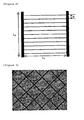
- the offset printing may be performed by using the method in which after the paste 5 is filled in the pattern of the intaglio I by using the doctor blade 2 as the first step; the first transferring is performed by rotating the blanket 3 (upper part of FIG. 1 ) and as a second step, the second transferring is performed on the resin film 4 by rotating the blanket 3.
- the intaglio may be manufactured by precisely etching the glass on which the desired electric conductive heating pattern is formed, and metal or DLC (diamond-like carbon) coating may be performed on the glass surface for the durability.
- the intaglio may be manufactured by etching the metal plate.
- FIG. 1 illustrates the offset printing method.
- the first transferring is performed by rotating the blanket, and as the second step, the second transferring is performed on the resin film by rotating the blanket.
- the conductive heating material metal that has an excellent thermal conductivity is used.
- the specific resistance value of the conductive heating pattern material is in the range of 1 microOhm cm to 200 microOhm cm.
- the conductive heating pattern material copper, silver, carbon nanotube (CNT) may be used, and silver is most preferable.
- the conductive heating material may be used in a particle form.
- the conductive heating pattern material copper particles that are coated with silver may be used.
- the paste may further include an organic binder in addition to the above conductive heating material so that the printing process is easily performed. It is preferable that the organic binder has a volatile property in the sintering process.
- the organic binder there are polyacryl resin, polyurethane resin, polyester resin, polyolefine resin, polycarbonate resin and cellulose resin, polyimide resin, polyethylene naphthalate resin and denatured epoxy resin, but it is not limited thereto.
- the paste may further include a glass frit.
- the glass frit may be selected from commercial products, but it is preferable to use the environmentally friendly glass frit that includes no lead component. In this case, it is preferable that the average diameter of the glass frit is 2 micrometers or less and the maximum diameter thereof is 50 micrometers or less.
- a solvent may be further added to the paste.
- the solvent there are butyl carbitol acetate, carbitol acetate, cyclohexanon, cellosolve acetate and terpineol, but it is not limited thereto.
- the weight ratio of the conductive heating material is 50 to 90%, the weight ratio of the organic binder is 1 to 20%, the weight ratio of the glass frit is 0.1 to 10% and the weight ratio of the solvent is 1 to 20%.
- the above paste may be printed so that the line width of the line that forms the conductive heating pattern is 50 micrometers or less, much more preferably 30 micrometers or less by using the printing method.
- the line width of the conductive heating pattern may be in the range of 5 micrometers to 30 micrometers by the printing method.
- the above heating pattern may be formed so that the line width and the line height are uniform by the method or it may artificially include the different line widths or line heights. That is, in the case of when the printing method is used by using the paste, it is possible to control the interval between lines of the conductive heating pattern.
- the opening ratio that is, the ratio of the area of the resin film that is not covered with the pattern is 70% or less
- the interval between the lines of conductive heating pattern is 30 mm or less.
- the interval between the lines of the conductive heating pattern is 200 micrometers or more and 30 mm or less.
- the height of the line from the resin film may be printed so that it is 1 to 100 micrometers, and preferably about 3 micrometers.
- the line width and line height of the heating pattern may be made uniform by the above methods.
- the uniformity of the heating pattern may be in the range of ⁇ 3 micrometers in the case of the line width and in the range of ⁇ 1 micrometer in the case of the line height.
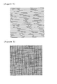
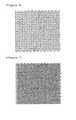
- the printing pattern may be stripe, diamond, rectangular lattice, circle, wave pattern, grid, 2-dimensional grid, and the like as shown in FIGS. 3 , 4 to 7 , but is not limited to a predetermined form, and it is preferable that it is designed so that light that is emitted from a predetermined light source does not suppress optical properties by diffraction and interference. That is, in order to minimize the regularity of the pattern, the spacing of the tide pattern, sine wave, and the lattice structure and the pattern where the line thickness is made nonuniform may be used. In addition, in order to improve the optical properties, various patterns as shown in FIG. 8 may be added in addition to the above pattern. In addition, the additional dot patterns may be irregularly formed while they are not connected to the above pattern.
- the patterns and the dot patterns have the size of 30 micrometers or less.
- the printing pattern may be a combination of two or more patterns.
- the line that configures the heating pattern may be formed of the straight lines, or various modifications such as curved lines, wave lines, and zigzag lines may be feasible.
- the line width and line height may be made uniform.
- at least a portion of the conductive heating pattern may be different from the remaining pattern.
- the desired heating pattern may be obtained by this configuration.
- the heating patterns of the corresponding area and the remaining area may be different from each other.
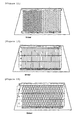
- the line widths and line intervals of the printing pattern may be different from each other so that at least a portion of the heating pattern is different from the remaining printing pattern. Therefore, the heating may more rapidly or efficiently occur at a desired place. That is, as shown in FIGS.
- the interval between the lines may be controlled, and as shown in FIGS. 12 to 14 , much heat emission may be obtained in the B area by using the large line width in the A and C areas and the small line width in the B area.
- the heating element according to an exemplary embodiment of the present invention may include at least two areas where the line widths or line intervals of the heating pattern are different.
- the heating element may include an area in which the conductive heating pattern is not formed. Transmission and reception that have a predetermined frequency can be performed by allowing at least a portion of the heating element not to form the conductive heating pattern, and information transmission and reception may be performed between the internal space and the external space.
- the area in which the conductive heating pattern is not formed may have an area that varies according to the desired frequency of the transmission and reception. For example, in order to pass the electromagnetic wave of 1.6 GHz that is used in the GPS, the area that has the long side that is 1/2 (9.4 cm) or more of the above wavelength is required.
- the area in which the conductive heating pattern is not formed may have an area that can transmit and receive the desired frequency, and its form is not particularly limited.
- the area in which the conductive heating pattern is not formed may the heating element that is provided with one or more semicircular areas that have the diameter of 5 to 20 cm.
- the conductive heating pattern may be blackened. If the paste that includes the metal material is sintered at the high temperature, metal gloss is shown, such that the visibility may be lowered because of the reflection of light. The problem may be prevented by blackening the conductive heating pattern.
- the blackening material may be added to the paste for forming the heating pattern or the blackening treatment may be performed after the paste is printed and sintered, thereby blackening the conductive heating pattern.
- the blackening material that may be added to the paste there are metal oxide, carbon black, carbon nanotube, black pigment, colored glass frit and the like.
- the composition of the paste may include 50 to 90 wt% of the conductive heating material, 1 to 20 wt% of organic binder, 1 to 10 wt% of blackening material, 0.1 to 10 wt% of glass frit, and 1 to 20 wt% of solvent.
- the composition of the paste may include 50 to 90 wt% of the conductive heating material, 1 to 20 wt% of organic binder, 0.1 to 10 wt% of glass frit, and 1 to 20 wt% of solvent.
- the blackening treatment after the sintering includes dipping into the oxidized solution, for example, solution that includes the Fe or Cu ion, dipping into the solution that includes halogen ions such as a chlorine ion, dipping into hydrogen peroxide and nitric acids, and treatment using the halogen gas.
- the resin film it is preferable to use the film that is formed of the polymer resin.
- the polymer resin one or more resins that are selected from a polyacryl-based resin, polyurethane-based resin, polyester-based resin, polyolefine-based resin, polycarbonate-based resin, cellulose-based resin, polyethylene naphthalate, PVB, and EVA may be used.
- the board that has the film form may be rigid or flexible.
- the conductive paste is most preferably a low sintering type silver conductive paste.
- the low temperature is 50 to 350°C, preferably 200°C or less, and more preferably 150°C or less.
- the resin film is PET (Polyethylene Terephthalate)
- the thickness of the resin film may be 12.5 to 500 micrometers and preferably 50 to 250 micrometers.
- the step for forming the bus bar at both ends of the conductive heating pattern the step for attaching the transparent substance to at least one side of the resin film that has the conductive heating pattern, and the step for providing the power portion that is connected to the bus bar are performed. These steps may use a method that is known in the art.
- the bus bar may be simultaneously formed in conjunction with the formation of the conductive heating pattern, and may be formed by using the other printing method after the conductive heating pattern is formed.
- the bus bar may be formed through the screen printing.
- the thickness of the bus bar is 1 to 100 micrometers and it is preferably 10 to 50 micrometers. If it is less than 1 micrometer, since the contact resistance between the conductive heating pattern and the bus bar is increased, local heating may be performed at the contact portion, and if it is less than 100 micrometers, the cost of the electrode material is increased.
- the connection between the bus bar and power may be performed through soldering and physical contact to the structure that has good conductive heat emission.
- the step for attaching the transparent substance to at least one side of the resin film that has the conductive heating pattern may be performed, for example, by inserting the resin film on which the conductive heating pattern is printed between the transparent substance and using two attachment films.
- the transparent substance may be a glass or plastic substrate or a plastic film.
- the heating element according to an exemplary embodiment of the present invention may include additional transparent substance on at least one side thereof.
- the attachment film may be used. In the course of attaching them, the temperature and pressure may be controlled.
- the attachment film is inserted between the heating element according to an exemplary embodiment of the present invention and additional transparent substance, and they are put into the vacuum bag, and reduced in pressure or increased in temperature or increased in temperature by using the hot roll, thus removing the air, thereby accomplishing first attachment.
- the pressure, temperature and time may vary according to the kind of the attachment film, and in general, the temperature may be gradually increased from normal temperature to 100°C at a pressure of 300 to 700 Torr. In this case, it is preferable that the time is generally 1 hour or less.
- the preliminarily attached layered structure that is first attached is subjected to the second attachment process by the autoclave process where the temperature is increased while the pressure is added in the autoclave.
- the second attachment varies according to the kind of the attachment film, but it is preferable that after the attachment is performed at the pressure of 140 bar or more and the temperature in the range of 130 to 150°C for 1 to 3 hours, it is slowly cooled.
- the method for attaching them through one step by using the vacuum laminator device unlike the above two step attachment process may be used.
- the attachment may be performed by stepwisely increasing the temperature to 80 to 150°C and cooling them so that the pressure is lowered (- 5 mbar) until the temperature is 100°C and thereafter the pressure is added (- 1000 mbar).
- any material that has an adhesive strength and is transparent after attaching may be used as the material of the adhesive film.
- the PVB film, EVA film, PU film and the like may be used, but is not limited thereto.
- the adhesive film is not particularly limited, but it is preferable that its thickness is in the range of 100 micrometers to 800 micrometers.
- the additional attached transparent substance may be formed of only the transparent substance and may be formed of the transparent substance that is provided with the conductive heating pattern that is manufactured as described above.
- the additional transparent substance may be a glass or plastic substrate or a plastic film.
- the heating element may include additional transparent substance on at least one side thereof.
- the transparent substance may be a glass or plastic substrate or a plastic film.
- the conductive heating pattern that is formed by the printing method may slightly vary according to the kind of the paste or the printing method, but the surface thereof may be rounded by the surface tension. This surface shape may not be formed by a known photolithography method.
- the vertical cross section of the pattern that is rounded may be a lenticular lens. It is preferable that the angle between the tangent at the contact point between the pattern and the surface of resin film and the surface of the resin film is 80° or less, preferably 75° or less, and more preferably 60° or less. It is preferable that in the rounded upper surface of the vertical cross section of the pattern, the straight line area is 1/50 or less in a circumference direction.
- the line width of the conductive heating pattern of the heating element is 50 micrometers or less, more preferably 30 micrometers or less, much more preferably 25 micrometers or less, and the interval between the lines is 30 mm or less, and the height of the line is 1 to 100 micrometers, and more preferably about 3 micrometers.
- the heating element according to an exemplary embodiment of the present invention may to the power for heat emission, and In this case, the heating amount is 100 to 700 W per m 2 , and preferably 200 to 300 W. Since the heating element according to an exemplary embodiment of the present invention has excellent heating performance at the low voltage, for example, 30 V or less, and preferably 20 V or less, it may be usefully used in vehicles and the like.
- the resistance of the heating element is 5 ohm/square or less, preferably 1 ohm/square or less, and more preferably 0.5 ohm/square or less.
- the heating element according to an exemplary embodiment of the present invention may have a shape of curved surface.
- the opening ratio of the conductive heating pattern that is, the area ratio of the resin film that is not covered with the pattern is 70% or more.
- the opening ratio of the pattern is constant in the unit area.
- the permeability deviation of the heating element is 5% or less in respects to a predetermined circle that has the diameter of 20 cm.
- the heating element may prevent the local heat emission.
- the standard deviation of the surface temperature of the transparent substance is within 20%, and preferably after the heat emission, within 10% for 5 min.
- the heating element according to an exemplary embodiment of the present invention has the conductive heating pattern that is formed by using, five or more pattern lines may be disposed per 1 cm of the length of the bus bar.
- the heating element that has the stripe shape according to FIG. 2 has the following physical properties.
- the line width w of the hot line is 20 micrometers
- the height h is 1.5 micrometers
- specific resistance p is 3*10-6 ⁇ cm
- the interval p between the lines is 300 micrometers
- L1 is 1 m
- L2 is 1 m
- R is 0.3 ⁇
- the opening ratio is 93.3%
- the heating element according to the exemplary embodiments of the present invention may be applied to glass that is used for various transport means such as vehicles, ships, railroads, high-speed railroads, and airplanes, houses or other buildings.
- the heating element according to the exemplary embodiments of the present invention since the heating element according to the exemplary embodiments of the present invention has an excellent heating property at a low voltage, can minimize side effects by diffraction and interference of single light source after sunset, and can be invisible in the above line width, unlike the known technology, it may be applied to the front window for transport means such as vehicles.
- the silver paste As the silver paste, the silver paste for low temperature sintering that is manufactured by Fujikura, Co., Ltd. was used.
- As the intaglio a glass that had patterns that had the interval of 300 micrometers, the width of 20 micrometers, and the depth of 7.5 micrometers and were orthogonally formed in a grid manner was used.
- the polyester-based primer was bar coated on the PET film (thickness of 125 micrometers), it was dried for 2 min to perform the primer treatment.
- the grid manner silver pattern was formed by using the manner shown in FIG. 1 and the offset printer, the silver line was formed by sintering it at 150°C for 30 min. In this case, the interval of the formed silver line was 300 micrometers, the width was 25 micrometers, the height was 1.5 micrometers, and the opening ratio was 84%.
- the substrate was cut in the size of 275 mm X 270 mm, it was disposed between the EVA that had the thickness of 400 micrometers, and the attachment glass was manufactured by putting the complex between glasses that had the thickness of 3 mm and the size of 270 mm X 270 mm and attaching them under 5 atm at 140°C for 30 min.
- the bus bar was formed by contacting the portion that was disposed outside the attachment glass in the long axis direction with the copper strip by using the clip. In this case, the resistance between both terminals was 5.4 ohm. In this case, when the voltage of 13 V was applied, the heating amount was 38 W (510 W/m 2 ).
- the temperature was increased from 20°C to 50°C within 5 min.
- the temperature deviation percentage value that was obtained by dividing the difference between the maximum value and the minimum value of the temperatures that were measured 20 points within the heating area by the average value was 7% or less for the measurement time.
Landscapes
- Surface Heating Bodies (AREA)
- Resistance Heating (AREA)
- Laminated Bodies (AREA)
- Joining Of Glass To Other Materials (AREA)
Claims (14)
- Verfahren zum Herstellen eines Heizelementes, wobei das Verfahren umfasst:Bestimmen einer Form eines Musters, in welchem eine Linienbreite 50 Mikrometer oder weniger ist und ein Öffnungsverhältnis in dem Bereich von 70% bis 99% ist;Drucken einer Paste (5), welche ein leitfähiges Heizmaterial entsprechend dem bestimmten Muster auf mindestens einer Seite eines Harzfilmes (4) einschließt;Bilden eines leitfähigen Heizmusters durch Sintern der Druckpaste (5), welche das leitfähige Heizmaterial einschließt;Bilden von Sammelschienen auf beiden Seiten des leitfähigen Heizmusters;Befestigen einer transparenten Substanz an mindestens einer Seite des Harzfilmes (4), welcher das leitfähige Heizmuster aufweist; undBereitstellen eines Leistungsteils, welches mit den Sammelschienen verbunden ist;wobei das Muster so konfiguriert ist, dass Abstand oder Liniendicke unregelmäßig ist, das Drucken ein Offsetdruckverfahren verwendet, undeine Transmissionsabweichung sichtbaren Lichts des Heizelementes 5% oder weniger, in Bezug zu einem vorbestimmten Kreis, welcher einen Durchmesser von 20 cm hat, ist.
- Verfahren zum Herstellen eines Heizelementes nach Anspruch 1, wobei das Drucken so durchgeführt wird, dass ein Intervall zwischen Linien der Druckmuster 30 mm oder weniger nach dem Sintern ist, und eine Höhe der Linie von der Oberfläche des transparenten Substrats in dem Bereich von 1 bis 100 Mikrometer ist.
- Verfahren zum Herstellen eines Heizelementes nach Anspruch 1, wobei das Muster ein oder mehrere Kombinationsmuster aus Streifen, Karo, Gitter, Kreis, Wellenmuster, Netz, zweidimensionalem Netz, Wechselmuster und Sinuswelle ist.
- Verfahren zum Herstellen eines Heizelementes nach Anspruch 1, weiter umfassend Schichten und Befestigen zusätzlicher transparenter Substanz auf mindestens einer Seite des Heizelementes.
- Heizelement, erhalten durch das Verfahren nach einem der Ansprüche 1 bis 4, wobei das Heizelement umfasst:a) einen Harzfilm (4);b) ein leitfähiges Heizmuster (5), welches auf mindestens einer Seite des Harzfilmes (4) angeordnet ist, wobei die Linienbreite des Musters, 50 Mikrometer oder weniger ist und das Öffnungsverhältnis des Musters, 70% bis 99% ist;c) Sammelschienen, welche an beiden Enden des leitfähigen Heizmusters angeordnet sind;d) ein Leistungsteil, welches mit den Sammelschienen verbunden ist; unde) eine transparente Substanz, welche auf mindestens einer Seite des Harzfilms bereitgestellt ist, auf welchem das leitfähige Heizmuster gebildet ist;wobei das Muster so konfiguriert ist, dass Abstand oder Liniendicke unregelmäßig ist,
das leitfähige Heizmuster durch Verwenden eines Offsetdruckverfahrens gebildet ist, und
die Transmissionsabweichung sichtbaren Lichts des Heizelementes 5% oder weniger, in Bezug auf einen vorbestimmten Kreis, der den Durchmesser von 20 cm hat, ist. - Heizelement nach Anspruch 5, wobei das Intervall zwischen Linien des leitfähigen Heizmusters 30 mm oder weniger ist, und die Höhe der Linie von der Oberfläche des transparenten Substrats in dem Bereich von 1 bis 100 Mikrometer ist.
- Heizelement nach Anspruch 5, wobei eine Temperaturabweichung innerhalb 5 min nach einem Heizbetrieb 10% oder weniger ist, durch eine Transmissionsabweichung des leitfähigen Heizmusters von 5% oder weniger, in Bezug auf einen vorbestimmten Kreis, der den Durchmesser von 20 cm hat.
- Heizelement nach Anspruch 5, wobei 5 oder mehr Musterlinien pro 1 cm der Länge der Sammelschiene angeordnet sind.
- Heizelement nach Anspruch 5, wobei das Heizelement mindestens zwei Bereiche, die verschiedene leitfähige Heizmuster haben, einschließt.
- Heizelement nach Anspruch 5, wobei das Heizelement einen Bereich einschließt, in welchem das leitfähige Heizmuster nicht so gebildet wird, dass der Bereich eine vorbestimmte Frequenz übermittelt und empfängt.
- Heizelement nach Anspruch 5, wobei das leitfähige Heizmuster geschwärzt ist.
- Heizelement nach Anspruch 5, wobei das Heizelement eine zusätzliche transparente Substanz enthält, welche auf dem Heizmuster c) bereitgestellt ist.
- Heizelement nach Anspruch 5, wobei das transparente Substrat ein Glas- oder Plastiksubstrat ist.
- Heizelement nach Anspruch 5, wobei das Heizelement für eine Frontscheibe von Fahrzeugen ist.
Applications Claiming Priority (13)
| Application Number | Priority Date | Filing Date | Title |
|---|---|---|---|
| KR20080024458 | 2008-03-17 | ||
| KR20080024461 | 2008-03-17 | ||
| KR20080024460 | 2008-03-17 | ||
| KR20080026546 | 2008-03-21 | ||
| KR20080026550 | 2008-03-21 | ||
| KR20080026548 | 2008-03-21 | ||
| KR20080026547 | 2008-03-21 | ||
| KR20080026545 | 2008-03-21 | ||
| KR20080045176 | 2008-05-15 | ||
| KR20080045177 | 2008-05-15 | ||
| KR20080045178 | 2008-05-15 | ||
| KR20080045179 | 2008-05-15 | ||
| PCT/KR2009/001339 WO2009116786A2 (ko) | 2008-03-17 | 2009-03-17 | 발열체 및 이의 제조방법 |
Publications (3)
| Publication Number | Publication Date |
|---|---|
| EP2275389A2 EP2275389A2 (de) | 2011-01-19 |
| EP2275389A4 EP2275389A4 (de) | 2011-08-03 |
| EP2275389B1 true EP2275389B1 (de) | 2013-09-18 |
Family
ID=41091387
Family Applications (1)
| Application Number | Title | Priority Date | Filing Date |
|---|---|---|---|
| EP09721668.3A Active EP2275389B1 (de) | 2008-03-17 | 2009-03-17 | Heizvorrichtung und herstellungsverfahren dafür |
Country Status (4)
| Country | Link |
|---|---|
| EP (1) | EP2275389B1 (de) |
| JP (1) | JP2011515809A (de) |
| KR (1) | KR101004171B1 (de) |
| WO (1) | WO2009116786A2 (de) |
Families Citing this family (33)
| Publication number | Priority date | Publication date | Assignee | Title |
|---|---|---|---|---|
| KR101265895B1 (ko) * | 2009-10-21 | 2013-05-20 | (주)엘지하우시스 | 발열 필름 및 그를 포함하는 발열 제품 |
| FR2953677B1 (fr) * | 2009-12-04 | 2020-11-06 | Saint Gobain | Vitrage a fils conducteurs integres par ultrasons |
| JP5385192B2 (ja) * | 2010-03-29 | 2014-01-08 | 富士フイルム株式会社 | パターン生成方法及びパターン生成プログラム |
| US20130020303A1 (en) * | 2010-04-01 | 2013-01-24 | Sujin Kim | Heating element and method for manufacturing same |
| JP5497555B2 (ja) * | 2010-06-30 | 2014-05-21 | 富士フイルム株式会社 | 透明導電性フイルム及び発熱ガラスの製造方法 |
| JP5548051B2 (ja) * | 2010-06-30 | 2014-07-16 | 富士フイルム株式会社 | 透明導電性フイルム及び発熱ガラスの製造方法 |
| KR101302257B1 (ko) * | 2011-01-13 | 2013-09-03 | 주식회사 엘지화학 | 발열체 및 이의 제조방법 |
| KR20140105408A (ko) * | 2013-02-22 | 2014-09-01 | 주식회사 엘지화학 | 발열체 및 이의 제조방법 |
| GB201404084D0 (en) | 2014-03-07 | 2014-04-23 | Pilkington Group Ltd | Glazing |
| DE102014107480B4 (de) | 2014-05-27 | 2016-02-04 | Webasto SE | Kunststoffheckscheibe mit Heckscheibenheizung und Verfahren zur Herstellung derselben |
| KR101871965B1 (ko) * | 2014-06-09 | 2018-07-31 | 미츠코 바바 | 발열체 |
| JP6589270B2 (ja) * | 2014-10-27 | 2019-10-16 | 大日本印刷株式会社 | 発熱板用の中間部材 |
| EP3656749B1 (de) | 2014-11-17 | 2021-11-17 | Dai Nippon Printing Co., Ltd. | Heizplatte, leitfähige musterschicht, fahrzeug und verfahren zur herstellung einer heizplatte |
| US10912155B2 (en) | 2014-11-17 | 2021-02-02 | Dai Nippon Printing Co., Ltd. | Heating plate, conductive pattern sheet, vehicle, and method of manufacturing heating plate |
| JP2016102056A (ja) * | 2014-11-17 | 2016-06-02 | 大日本印刷株式会社 | 合わせガラス及びその製造方法 |
| JP2016102055A (ja) * | 2014-11-17 | 2016-06-02 | 大日本印刷株式会社 | 合わせガラス、パターンシート及び合わせガラスの製造方法 |
| JP6293722B2 (ja) * | 2014-12-01 | 2018-03-14 | 大日本印刷株式会社 | 合わせガラス及び合わせガラス用パターンシート |
| JP6840452B2 (ja) * | 2015-01-30 | 2021-03-10 | 大日本印刷株式会社 | 合わせガラスおよび導電性発熱体 |
| JP6976676B2 (ja) * | 2015-03-31 | 2021-12-08 | 大日本印刷株式会社 | 透明発熱板及び乗り物 |
| US20190159296A1 (en) * | 2015-11-17 | 2019-05-23 | Dai Nippon Printing Co., Ltd. | Heating electrode device, electrical heating glass, heat-generating plate, vehicle, window for building, sheet with conductor, conductive pattern sheet, conductive heat-generating body, laminated glass, and manufacturing method for conductive heat-generating body |
| JP6913294B2 (ja) * | 2015-12-16 | 2021-08-04 | 大日本印刷株式会社 | 発熱板、導電体付きシート、乗り物及び建築物用窓 |
| KR102069936B1 (ko) | 2016-04-29 | 2020-01-23 | 주식회사 엘지화학 | 발열체 |
| JP2017204388A (ja) * | 2016-05-11 | 2017-11-16 | 大日本印刷株式会社 | 導電性発熱体および合わせガラス |
| FR3056069A1 (fr) * | 2016-09-13 | 2018-03-16 | Commissariat A L'energie Atomique Et Aux Energies Alternatives | Reseau percolant de nanofils pour chauffage grande surface. |
| FR3056070B1 (fr) * | 2016-09-13 | 2018-10-05 | Commissariat A L'energie Atomique Et Aux Energies Alternatives | Reseau percolant de nanofils pour chauffage localise. |
| JP6905831B2 (ja) * | 2017-01-19 | 2021-07-21 | 日本板硝子株式会社 | 合わせガラス |
| KR102251892B1 (ko) * | 2017-04-13 | 2021-05-14 | 엘지이노텍 주식회사 | 발열 장치 |
| JP7311948B2 (ja) * | 2017-11-29 | 2023-07-20 | 日本板硝子株式会社 | ウインドシールド |
| JP6984388B2 (ja) * | 2017-12-20 | 2021-12-17 | 住友ベークライト株式会社 | 構造体および内装材 |
| WO2020129420A1 (ja) * | 2018-12-21 | 2020-06-25 | Agc株式会社 | 合わせガラス |
| DE102019111546A1 (de) * | 2019-05-03 | 2020-11-05 | Irlbacher Blickpunkt Glas Gmbh | Leuchte mit einer Beschichtung zur Enteisung |
| JP6818260B2 (ja) * | 2019-09-18 | 2021-01-20 | 大日本印刷株式会社 | 発熱板用の中間部材 |
| WO2023120024A1 (ja) * | 2021-12-24 | 2023-06-29 | 富士フイルム株式会社 | 透明発熱体および透明発熱成形体 |
Citations (1)
| Publication number | Priority date | Publication date | Assignee | Title |
|---|---|---|---|---|
| EP0594932A1 (de) * | 1992-10-27 | 1994-05-04 | Matsushita Electric Industrial Co., Ltd. | Verfahren zur Herstellung eines transparenten Musters aus leitendem Film |
Family Cites Families (17)
| Publication number | Priority date | Publication date | Assignee | Title |
|---|---|---|---|---|
| NL8100601A (nl) * | 1981-02-09 | 1982-09-01 | Philips Nv | Ruit voorzien van elektrische draad en draad. |
| GB8705075D0 (en) * | 1987-03-04 | 1987-04-08 | Pilkington Brothers Plc | Printing |
| JPH02165591A (ja) * | 1988-12-20 | 1990-06-26 | Nippon Sheet Glass Co Ltd | 自動車窓用ヒータ線の導体印刷パターン作図装置 |
| JPH0728740U (ja) * | 1993-11-09 | 1995-05-30 | タムステクノロジー株式会社 | 自動車用曇り止め機能付ミラー |
| JPH0872674A (ja) * | 1994-07-08 | 1996-03-19 | Asahi Glass Co Ltd | 電熱窓ガラス |
| JPH11322361A (ja) * | 1998-05-08 | 1999-11-24 | Asahi Glass Co Ltd | 導電性ペースト及び導電体付ガラス板 |
| DE10126869A1 (de) * | 2001-06-01 | 2002-12-19 | Saint Gobain Sekurit D Gmbh | Elektrisch beheizbare Scheibe |
| JP2003157958A (ja) * | 2001-11-20 | 2003-05-30 | Matsushita Electric Ind Co Ltd | 面状発熱体 |
| KR200287050Y1 (ko) * | 2002-05-20 | 2002-08-30 | 황종하 | 산화주석코팅유리를 활용한 투명면상접합발열유리 |
| GB0408392D0 (en) * | 2004-04-15 | 2004-05-19 | Pilkington Plc | Electrically heated window |
| EP1748034A4 (de) * | 2004-04-28 | 2008-05-28 | Asahi Glass Co Ltd | Glasplatte mit leitfähigem aufdruck und herstellungsverfahren dafür |
| JP4679087B2 (ja) * | 2004-07-09 | 2011-04-27 | グンゼ株式会社 | 透明面状発熱体及びその製造方法 |
| JP4679088B2 (ja) * | 2004-07-09 | 2011-04-27 | グンゼ株式会社 | 透明面状発熱体及びその製造方法 |
| GB0427749D0 (en) * | 2004-12-18 | 2005-01-19 | Pilkington Plc | Electrically heated window |
| CN101129092A (zh) * | 2005-02-24 | 2008-02-20 | 埃克阿泰克有限责任公司 | 脉冲宽度调制的除霜器 |
| US7656357B2 (en) * | 2005-04-01 | 2010-02-02 | Nissha Printing Co., Ltd. | Transparent antenna for vehicle and vehicle glass with antenna |
| JP4971716B2 (ja) * | 2006-08-10 | 2012-07-11 | 日本板硝子株式会社 | 導電性セラミックス焼結体付き車両用窓ガラス及びその製造方法 |
-
2009
- 2009-03-17 WO PCT/KR2009/001339 patent/WO2009116786A2/ko active Application Filing
- 2009-03-17 EP EP09721668.3A patent/EP2275389B1/de active Active
- 2009-03-17 KR KR1020090022808A patent/KR101004171B1/ko active IP Right Grant
- 2009-03-17 JP JP2011500699A patent/JP2011515809A/ja active Pending
Patent Citations (1)
| Publication number | Priority date | Publication date | Assignee | Title |
|---|---|---|---|---|
| EP0594932A1 (de) * | 1992-10-27 | 1994-05-04 | Matsushita Electric Industrial Co., Ltd. | Verfahren zur Herstellung eines transparenten Musters aus leitendem Film |
Also Published As
| Publication number | Publication date |
|---|---|
| JP2011515809A (ja) | 2011-05-19 |
| KR101004171B1 (ko) | 2010-12-24 |
| WO2009116786A2 (ko) | 2009-09-24 |
| KR20090099503A (ko) | 2009-09-22 |
| EP2275389A4 (de) | 2011-08-03 |
| WO2009116786A3 (ko) | 2009-12-17 |
| EP2275389A2 (de) | 2011-01-19 |
Similar Documents
| Publication | Publication Date | Title |
|---|---|---|
| EP2275389B1 (de) | Heizvorrichtung und herstellungsverfahren dafür | |
| EP2257120B1 (de) | Heizelement und herstellungsverfahren dafür | |
| EP2284134B1 (de) | Erwärmungselement und herstellungsverfahren dafür | |
| US20110017719A1 (en) | Heater and manufacturing method for same | |
| EP2314552B1 (de) | Heizelement und herstellungsverfahren dafür | |
| EP2521422B1 (de) | Erwärmungselement und herstellungsverfahren dafür | |
| EP2618632B1 (de) | Erwärmungselement und herstellungsverfahren dafür | |
| EP2928264B1 (de) | Heizelement und verfahren zur herstellung davon | |
| EP2381739B1 (de) | Erwärmungselement und herstellungsverfahren dafür | |
| EP2844031A1 (de) | Heizelement und herstellungsverfahren dafür | |
| US20170238373A1 (en) | Heating element and manufacturing method therefor | |
| EP2665337A2 (de) | Heizelement und herstellungsverfahren dafür | |
| US10412788B2 (en) | Heating element and manufacturing method thereof |
Legal Events
| Date | Code | Title | Description |
|---|---|---|---|
| PUAI | Public reference made under article 153(3) epc to a published international application that has entered the european phase |
Free format text: ORIGINAL CODE: 0009012 |
|
| 17P | Request for examination filed |
Effective date: 20100916 |
|
| AK | Designated contracting states |
Kind code of ref document: A2 Designated state(s): AT BE BG CH CY CZ DE DK EE ES FI FR GB GR HR HU IE IS IT LI LT LU LV MC MK MT NL NO PL PT RO SE SI SK TR |
|
| AX | Request for extension of the european patent |
Extension state: AL BA RS |
|
| DAX | Request for extension of the european patent (deleted) | ||
| A4 | Supplementary search report drawn up and despatched |
Effective date: 20110706 |
|
| RIC1 | Information provided on ipc code assigned before grant |
Ipc: C03C 27/06 20060101AFI20110630BHEP Ipc: H05B 3/84 20060101ALI20110630BHEP |
|
| 17Q | First examination report despatched |
Effective date: 20120216 |
|
| GRAP | Despatch of communication of intention to grant a patent |
Free format text: ORIGINAL CODE: EPIDOSNIGR1 |
|
| INTG | Intention to grant announced |
Effective date: 20130429 |
|
| GRAS | Grant fee paid |
Free format text: ORIGINAL CODE: EPIDOSNIGR3 |
|
| GRAA | (expected) grant |
Free format text: ORIGINAL CODE: 0009210 |
|
| AK | Designated contracting states |
Kind code of ref document: B1 Designated state(s): AT BE BG CH CY CZ DE DK EE ES FI FR GB GR HR HU IE IS IT LI LT LU LV MC MK MT NL NO PL PT RO SE SI SK TR |
|
| REG | Reference to a national code |
Ref country code: GB Ref legal event code: FG4D |
|
| REG | Reference to a national code |
Ref country code: CH Ref legal event code: EP |
|
| REG | Reference to a national code |
Ref country code: IE Ref legal event code: FG4D |
|
| REG | Reference to a national code |
Ref country code: AT Ref legal event code: REF Ref document number: 632670 Country of ref document: AT Kind code of ref document: T Effective date: 20131015 |
|
| REG | Reference to a national code |
Ref country code: DE Ref legal event code: R096 Ref document number: 602009018889 Country of ref document: DE Effective date: 20131114 |
|
| REG | Reference to a national code |
Ref country code: SE Ref legal event code: TRGR |
|
| PG25 | Lapsed in a contracting state [announced via postgrant information from national office to epo] |
Ref country code: CY Free format text: LAPSE BECAUSE OF FAILURE TO SUBMIT A TRANSLATION OF THE DESCRIPTION OR TO PAY THE FEE WITHIN THE PRESCRIBED TIME-LIMIT Effective date: 20130918 Ref country code: HR Free format text: LAPSE BECAUSE OF FAILURE TO SUBMIT A TRANSLATION OF THE DESCRIPTION OR TO PAY THE FEE WITHIN THE PRESCRIBED TIME-LIMIT Effective date: 20130918 Ref country code: NO Free format text: LAPSE BECAUSE OF FAILURE TO SUBMIT A TRANSLATION OF THE DESCRIPTION OR TO PAY THE FEE WITHIN THE PRESCRIBED TIME-LIMIT Effective date: 20131218 Ref country code: LT Free format text: LAPSE BECAUSE OF FAILURE TO SUBMIT A TRANSLATION OF THE DESCRIPTION OR TO PAY THE FEE WITHIN THE PRESCRIBED TIME-LIMIT Effective date: 20130918 |
|
| REG | Reference to a national code |
Ref country code: NL Ref legal event code: VDEP Effective date: 20130918 |
|
| REG | Reference to a national code |
Ref country code: AT Ref legal event code: MK05 Ref document number: 632670 Country of ref document: AT Kind code of ref document: T Effective date: 20130918 |
|
| REG | Reference to a national code |
Ref country code: LT Ref legal event code: MG4D |
|
| PG25 | Lapsed in a contracting state [announced via postgrant information from national office to epo] |
Ref country code: GR Free format text: LAPSE BECAUSE OF FAILURE TO SUBMIT A TRANSLATION OF THE DESCRIPTION OR TO PAY THE FEE WITHIN THE PRESCRIBED TIME-LIMIT Effective date: 20131219 Ref country code: LV Free format text: LAPSE BECAUSE OF FAILURE TO SUBMIT A TRANSLATION OF THE DESCRIPTION OR TO PAY THE FEE WITHIN THE PRESCRIBED TIME-LIMIT Effective date: 20130918 Ref country code: FI Free format text: LAPSE BECAUSE OF FAILURE TO SUBMIT A TRANSLATION OF THE DESCRIPTION OR TO PAY THE FEE WITHIN THE PRESCRIBED TIME-LIMIT Effective date: 20130918 Ref country code: SI Free format text: LAPSE BECAUSE OF FAILURE TO SUBMIT A TRANSLATION OF THE DESCRIPTION OR TO PAY THE FEE WITHIN THE PRESCRIBED TIME-LIMIT Effective date: 20130918 |
|
| PG25 | Lapsed in a contracting state [announced via postgrant information from national office to epo] |
Ref country code: BE Free format text: LAPSE BECAUSE OF FAILURE TO SUBMIT A TRANSLATION OF THE DESCRIPTION OR TO PAY THE FEE WITHIN THE PRESCRIBED TIME-LIMIT Effective date: 20130918 |
|
| PG25 | Lapsed in a contracting state [announced via postgrant information from national office to epo] |
Ref country code: NL Free format text: LAPSE BECAUSE OF FAILURE TO SUBMIT A TRANSLATION OF THE DESCRIPTION OR TO PAY THE FEE WITHIN THE PRESCRIBED TIME-LIMIT Effective date: 20130918 Ref country code: CZ Free format text: LAPSE BECAUSE OF FAILURE TO SUBMIT A TRANSLATION OF THE DESCRIPTION OR TO PAY THE FEE WITHIN THE PRESCRIBED TIME-LIMIT Effective date: 20130918 Ref country code: EE Free format text: LAPSE BECAUSE OF FAILURE TO SUBMIT A TRANSLATION OF THE DESCRIPTION OR TO PAY THE FEE WITHIN THE PRESCRIBED TIME-LIMIT Effective date: 20130918 Ref country code: SK Free format text: LAPSE BECAUSE OF FAILURE TO SUBMIT A TRANSLATION OF THE DESCRIPTION OR TO PAY THE FEE WITHIN THE PRESCRIBED TIME-LIMIT Effective date: 20130918 Ref country code: IS Free format text: LAPSE BECAUSE OF FAILURE TO SUBMIT A TRANSLATION OF THE DESCRIPTION OR TO PAY THE FEE WITHIN THE PRESCRIBED TIME-LIMIT Effective date: 20140118 |
|
| PG25 | Lapsed in a contracting state [announced via postgrant information from national office to epo] |
Ref country code: PL Free format text: LAPSE BECAUSE OF FAILURE TO SUBMIT A TRANSLATION OF THE DESCRIPTION OR TO PAY THE FEE WITHIN THE PRESCRIBED TIME-LIMIT Effective date: 20130918 Ref country code: ES Free format text: LAPSE BECAUSE OF FAILURE TO SUBMIT A TRANSLATION OF THE DESCRIPTION OR TO PAY THE FEE WITHIN THE PRESCRIBED TIME-LIMIT Effective date: 20130918 Ref country code: AT Free format text: LAPSE BECAUSE OF FAILURE TO SUBMIT A TRANSLATION OF THE DESCRIPTION OR TO PAY THE FEE WITHIN THE PRESCRIBED TIME-LIMIT Effective date: 20130918 |
|
| REG | Reference to a national code |
Ref country code: DE Ref legal event code: R097 Ref document number: 602009018889 Country of ref document: DE |
|
| PG25 | Lapsed in a contracting state [announced via postgrant information from national office to epo] |
Ref country code: PT Free format text: LAPSE BECAUSE OF FAILURE TO SUBMIT A TRANSLATION OF THE DESCRIPTION OR TO PAY THE FEE WITHIN THE PRESCRIBED TIME-LIMIT Effective date: 20140120 |
|
| PLBE | No opposition filed within time limit |
Free format text: ORIGINAL CODE: 0009261 |
|
| STAA | Information on the status of an ep patent application or granted ep patent |
Free format text: STATUS: NO OPPOSITION FILED WITHIN TIME LIMIT |
|
| 26N | No opposition filed |
Effective date: 20140619 |
|
| PG25 | Lapsed in a contracting state [announced via postgrant information from national office to epo] |
Ref country code: IT Free format text: LAPSE BECAUSE OF FAILURE TO SUBMIT A TRANSLATION OF THE DESCRIPTION OR TO PAY THE FEE WITHIN THE PRESCRIBED TIME-LIMIT Effective date: 20130918 |
|
| PG25 | Lapsed in a contracting state [announced via postgrant information from national office to epo] |
Ref country code: DK Free format text: LAPSE BECAUSE OF FAILURE TO SUBMIT A TRANSLATION OF THE DESCRIPTION OR TO PAY THE FEE WITHIN THE PRESCRIBED TIME-LIMIT Effective date: 20130918 |
|
| REG | Reference to a national code |
Ref country code: DE Ref legal event code: R097 Ref document number: 602009018889 Country of ref document: DE Effective date: 20140619 |
|
| PG25 | Lapsed in a contracting state [announced via postgrant information from national office to epo] |
Ref country code: LU Free format text: LAPSE BECAUSE OF FAILURE TO SUBMIT A TRANSLATION OF THE DESCRIPTION OR TO PAY THE FEE WITHIN THE PRESCRIBED TIME-LIMIT Effective date: 20140317 |
|
| REG | Reference to a national code |
Ref country code: CH Ref legal event code: PL |
|
| REG | Reference to a national code |
Ref country code: IE Ref legal event code: MM4A |
|
| PG25 | Lapsed in a contracting state [announced via postgrant information from national office to epo] |
Ref country code: CH Free format text: LAPSE BECAUSE OF NON-PAYMENT OF DUE FEES Effective date: 20140331 Ref country code: IE Free format text: LAPSE BECAUSE OF NON-PAYMENT OF DUE FEES Effective date: 20140317 Ref country code: LI Free format text: LAPSE BECAUSE OF NON-PAYMENT OF DUE FEES Effective date: 20140331 |
|
| REG | Reference to a national code |
Ref country code: FR Ref legal event code: PLFP Year of fee payment: 8 |
|
| PG25 | Lapsed in a contracting state [announced via postgrant information from national office to epo] |
Ref country code: MT Free format text: LAPSE BECAUSE OF FAILURE TO SUBMIT A TRANSLATION OF THE DESCRIPTION OR TO PAY THE FEE WITHIN THE PRESCRIBED TIME-LIMIT Effective date: 20130918 |
|
| PG25 | Lapsed in a contracting state [announced via postgrant information from national office to epo] |
Ref country code: MC Free format text: LAPSE BECAUSE OF FAILURE TO SUBMIT A TRANSLATION OF THE DESCRIPTION OR TO PAY THE FEE WITHIN THE PRESCRIBED TIME-LIMIT Effective date: 20130918 Ref country code: RO Free format text: LAPSE BECAUSE OF FAILURE TO SUBMIT A TRANSLATION OF THE DESCRIPTION OR TO PAY THE FEE WITHIN THE PRESCRIBED TIME-LIMIT Effective date: 20130918 |
|
| PG25 | Lapsed in a contracting state [announced via postgrant information from national office to epo] |
Ref country code: BG Free format text: LAPSE BECAUSE OF FAILURE TO SUBMIT A TRANSLATION OF THE DESCRIPTION OR TO PAY THE FEE WITHIN THE PRESCRIBED TIME-LIMIT Effective date: 20130918 |
|
| PG25 | Lapsed in a contracting state [announced via postgrant information from national office to epo] |
Ref country code: TR Free format text: LAPSE BECAUSE OF FAILURE TO SUBMIT A TRANSLATION OF THE DESCRIPTION OR TO PAY THE FEE WITHIN THE PRESCRIBED TIME-LIMIT Effective date: 20130918 Ref country code: HU Free format text: LAPSE BECAUSE OF FAILURE TO SUBMIT A TRANSLATION OF THE DESCRIPTION OR TO PAY THE FEE WITHIN THE PRESCRIBED TIME-LIMIT; INVALID AB INITIO Effective date: 20090317 |
|
| REG | Reference to a national code |
Ref country code: FR Ref legal event code: PLFP Year of fee payment: 9 |
|
| REG | Reference to a national code |
Ref country code: FR Ref legal event code: PLFP Year of fee payment: 10 |
|
| PG25 | Lapsed in a contracting state [announced via postgrant information from national office to epo] |
Ref country code: MK Free format text: LAPSE BECAUSE OF FAILURE TO SUBMIT A TRANSLATION OF THE DESCRIPTION OR TO PAY THE FEE WITHIN THE PRESCRIBED TIME-LIMIT Effective date: 20130918 |
|
| PGFP | Annual fee paid to national office [announced via postgrant information from national office to epo] |
Ref country code: DE Payment date: 20240220 Year of fee payment: 16 Ref country code: GB Payment date: 20240220 Year of fee payment: 16 |
|
| PGFP | Annual fee paid to national office [announced via postgrant information from national office to epo] |
Ref country code: SE Payment date: 20240220 Year of fee payment: 16 Ref country code: FR Payment date: 20240226 Year of fee payment: 16 |