EP2268405B1 - Vorrichtung zur plasmaseparation - Google Patents
Vorrichtung zur plasmaseparation Download PDFInfo
- Publication number
- EP2268405B1 EP2268405B1 EP09714713.6A EP09714713A EP2268405B1 EP 2268405 B1 EP2268405 B1 EP 2268405B1 EP 09714713 A EP09714713 A EP 09714713A EP 2268405 B1 EP2268405 B1 EP 2268405B1
- Authority
- EP
- European Patent Office
- Prior art keywords
- channel
- membrane
- sample liquid
- filling
- punch
- Prior art date
- Legal status (The legal status is an assumption and is not a legal conclusion. Google has not performed a legal analysis and makes no representation as to the accuracy of the status listed.)
- Active
Links
Images


Classifications
-
- B—PERFORMING OPERATIONS; TRANSPORTING
- B01—PHYSICAL OR CHEMICAL PROCESSES OR APPARATUS IN GENERAL
- B01L—CHEMICAL OR PHYSICAL LABORATORY APPARATUS FOR GENERAL USE
- B01L3/00—Containers or dishes for laboratory use, e.g. laboratory glassware; Droppers
- B01L3/50—Containers for the purpose of retaining a material to be analysed, e.g. test tubes
- B01L3/502—Containers for the purpose of retaining a material to be analysed, e.g. test tubes with fluid transport, e.g. in multi-compartment structures
- B01L3/5027—Containers for the purpose of retaining a material to be analysed, e.g. test tubes with fluid transport, e.g. in multi-compartment structures by integrated microfluidic structures, i.e. dimensions of channels and chambers are such that surface tension forces are important, e.g. lab-on-a-chip
- B01L3/502753—Containers for the purpose of retaining a material to be analysed, e.g. test tubes with fluid transport, e.g. in multi-compartment structures by integrated microfluidic structures, i.e. dimensions of channels and chambers are such that surface tension forces are important, e.g. lab-on-a-chip characterised by bulk separation arrangements on lab-on-a-chip devices, e.g. for filtration or centrifugation
-
- B—PERFORMING OPERATIONS; TRANSPORTING
- B01—PHYSICAL OR CHEMICAL PROCESSES OR APPARATUS IN GENERAL
- B01D—SEPARATION
- B01D29/00—Filters with filtering elements stationary during filtration, e.g. pressure or suction filters, not covered by groups B01D24/00 - B01D27/00; Filtering elements therefor
- B01D29/01—Filters with filtering elements stationary during filtration, e.g. pressure or suction filters, not covered by groups B01D24/00 - B01D27/00; Filtering elements therefor with flat filtering elements
- B01D29/014—Filters with filtering elements stationary during filtration, e.g. pressure or suction filters, not covered by groups B01D24/00 - B01D27/00; Filtering elements therefor with flat filtering elements with curved filtering elements
-
- B—PERFORMING OPERATIONS; TRANSPORTING
- B01—PHYSICAL OR CHEMICAL PROCESSES OR APPARATUS IN GENERAL
- B01D—SEPARATION
- B01D29/00—Filters with filtering elements stationary during filtration, e.g. pressure or suction filters, not covered by groups B01D24/00 - B01D27/00; Filtering elements therefor
- B01D29/01—Filters with filtering elements stationary during filtration, e.g. pressure or suction filters, not covered by groups B01D24/00 - B01D27/00; Filtering elements therefor with flat filtering elements
- B01D29/05—Filters with filtering elements stationary during filtration, e.g. pressure or suction filters, not covered by groups B01D24/00 - B01D27/00; Filtering elements therefor with flat filtering elements supported
-
- B—PERFORMING OPERATIONS; TRANSPORTING
- B01—PHYSICAL OR CHEMICAL PROCESSES OR APPARATUS IN GENERAL
- B01D—SEPARATION
- B01D63/00—Apparatus in general for separation processes using semi-permeable membranes
- B01D63/08—Flat membrane modules
-
- B—PERFORMING OPERATIONS; TRANSPORTING
- B01—PHYSICAL OR CHEMICAL PROCESSES OR APPARATUS IN GENERAL
- B01D—SEPARATION
- B01D63/00—Apparatus in general for separation processes using semi-permeable membranes
- B01D63/08—Flat membrane modules
- B01D63/087—Single membrane modules
-
- B—PERFORMING OPERATIONS; TRANSPORTING
- B01—PHYSICAL OR CHEMICAL PROCESSES OR APPARATUS IN GENERAL
- B01D—SEPARATION
- B01D63/00—Apparatus in general for separation processes using semi-permeable membranes
- B01D63/08—Flat membrane modules
- B01D63/088—Microfluidic devices comprising semi-permeable flat membranes
-
- B—PERFORMING OPERATIONS; TRANSPORTING
- B01—PHYSICAL OR CHEMICAL PROCESSES OR APPARATUS IN GENERAL
- B01L—CHEMICAL OR PHYSICAL LABORATORY APPARATUS FOR GENERAL USE
- B01L3/00—Containers or dishes for laboratory use, e.g. laboratory glassware; Droppers
- B01L3/50—Containers for the purpose of retaining a material to be analysed, e.g. test tubes
- B01L3/502—Containers for the purpose of retaining a material to be analysed, e.g. test tubes with fluid transport, e.g. in multi-compartment structures
- B01L3/5027—Containers for the purpose of retaining a material to be analysed, e.g. test tubes with fluid transport, e.g. in multi-compartment structures by integrated microfluidic structures, i.e. dimensions of channels and chambers are such that surface tension forces are important, e.g. lab-on-a-chip
- B01L3/502715—Containers for the purpose of retaining a material to be analysed, e.g. test tubes with fluid transport, e.g. in multi-compartment structures by integrated microfluidic structures, i.e. dimensions of channels and chambers are such that surface tension forces are important, e.g. lab-on-a-chip characterised by interfacing components, e.g. fluidic, electrical, optical or mechanical interfaces
-
- G—PHYSICS
- G01—MEASURING; TESTING
- G01N—INVESTIGATING OR ANALYSING MATERIALS BY DETERMINING THEIR CHEMICAL OR PHYSICAL PROPERTIES
- G01N33/00—Investigating or analysing materials by specific methods not covered by groups G01N1/00 - G01N31/00
- G01N33/48—Biological material, e.g. blood, urine; Haemocytometers
- G01N33/483—Physical analysis of biological material
- G01N33/487—Physical analysis of biological material of liquid biological material
- G01N33/49—Blood
- G01N33/491—Blood by separating the blood components
-
- B—PERFORMING OPERATIONS; TRANSPORTING
- B01—PHYSICAL OR CHEMICAL PROCESSES OR APPARATUS IN GENERAL
- B01D—SEPARATION
- B01D2201/00—Details relating to filtering apparatus
- B01D2201/04—Supports for the filtering elements
- B01D2201/0415—Details of supporting structures
-
- B—PERFORMING OPERATIONS; TRANSPORTING
- B01—PHYSICAL OR CHEMICAL PROCESSES OR APPARATUS IN GENERAL
- B01D—SEPARATION
- B01D2201/00—Details relating to filtering apparatus
- B01D2201/44—Special measures allowing the even or uniform distribution of fluid along the length of a conduit
-
- B—PERFORMING OPERATIONS; TRANSPORTING
- B01—PHYSICAL OR CHEMICAL PROCESSES OR APPARATUS IN GENERAL
- B01D—SEPARATION
- B01D61/00—Processes of separation using semi-permeable membranes, e.g. dialysis, osmosis or ultrafiltration; Apparatus, accessories or auxiliary operations specially adapted therefor
- B01D61/14—Ultrafiltration; Microfiltration
- B01D61/18—Apparatus therefor
-
- B—PERFORMING OPERATIONS; TRANSPORTING
- B01—PHYSICAL OR CHEMICAL PROCESSES OR APPARATUS IN GENERAL
- B01L—CHEMICAL OR PHYSICAL LABORATORY APPARATUS FOR GENERAL USE
- B01L2300/00—Additional constructional details
- B01L2300/06—Auxiliary integrated devices, integrated components
- B01L2300/0681—Filter
-
- B—PERFORMING OPERATIONS; TRANSPORTING
- B01—PHYSICAL OR CHEMICAL PROCESSES OR APPARATUS IN GENERAL
- B01L—CHEMICAL OR PHYSICAL LABORATORY APPARATUS FOR GENERAL USE
- B01L2300/00—Additional constructional details
- B01L2300/08—Geometry, shape and general structure
- B01L2300/0861—Configuration of multiple channels and/or chambers in a single devices
- B01L2300/0864—Configuration of multiple channels and/or chambers in a single devices comprising only one inlet and multiple receiving wells, e.g. for separation, splitting
-
- B—PERFORMING OPERATIONS; TRANSPORTING
- B01—PHYSICAL OR CHEMICAL PROCESSES OR APPARATUS IN GENERAL
- B01L—CHEMICAL OR PHYSICAL LABORATORY APPARATUS FOR GENERAL USE
- B01L2400/00—Moving or stopping fluids
- B01L2400/04—Moving fluids with specific forces or mechanical means
- B01L2400/0403—Moving fluids with specific forces or mechanical means specific forces
- B01L2400/0406—Moving fluids with specific forces or mechanical means specific forces capillary forces
Definitions
- the present invention relates to a device for receiving blood and separating blood components, such as blood plasma, as a sample liquid.
- the present invention is concerned with microfluidic systems.
- the following statements relate to devices in which act capillary forces and are particularly crucial for the function.
- a device for separating blood plasma from blood by means of a Trennabutter, in particular a membrane is known, wherein the separated blood plasma is derived by capillary force in a channel.
- the present invention has for its object to provide an improved apparatus and an improved method for receiving blood and separation of blood components, such as blood plasma, as sample liquid, wherein an optimized filling of the channel with sample liquid is made possible and wherein a capillary contact between the separation element and the Channel is made and preferably the diagnostic or investigation options can be improved.
- blood components such as blood plasma
- a basic idea of the present invention is to provide a device for producing a fluidic capillary contact between separation elements, in particular membranes and a duct. This allows for optimal, fast and even filling of the channel and prevents unwanted air pockets.
- the sample liquid is taken up by capillary forces in a channel, is formed open at least on one narrow side or longitudinal side, so that a lateral liquid stop for the sample liquid is formed in the channel and the sample liquid can be guided sidewall free in the channel.
- a recess connects laterally to the open side of the channel.
- the laterally open design of the channel allows improved, in particular optimal ventilation when filling the channel with sample liquid.
- the side wall free held or guided surface of the sample liquid allows a direct examination of the sample liquid, in particular by coupling light, without an otherwise existing side wall o.
- the recess is trench-like and surrounds the channel, in particular laterally open, completely.
- the inner edges which otherwise occur during the transition from flat sides to narrow sides with particularly high capillary forces can be avoided altogether.
- the recess or side wall adjoining the channel laterally can also be filled with sample liquid or another liquid.
- the recess or side wall is then such - in particular with regard to their size, curvature or wetting behavior - or designed by guide elements that the filling speed of the channel with the sample liquid is greater than or equal to the filling speed of the recess or along the side wall in the filling direction - in particular longitudinal direction - the channel is.
- a lateral Vorschiessen the liquid front when filling with sample liquid can also be avoided.
- Another proposed method for determining a parameter in the blood plasma or a blood component is characterized in that in a microfluidic system directly after the retention or separation of blood cells directly a determination of a component or parameter of the blood plasma by means of a chemical or more chemicals , This allows a simple and compact design a quick and inexpensive analysis or determination of the parameter.
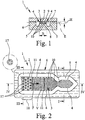
- Fig. 1 shows a schematic section of a first embodiment of a proposed device (1) for receiving and / or diagnosis of a sample liquid (2), in particular blood plasma o.
- the device (1) has a sample liquid (2) by capillary forces receiving channel (3 ) on.
- the channel (3) is open on at least one narrow side or longitudinal side (4), in the representation example on both narrow or long sides (4), as in Fig. 1 indicated. Laterally adjoins the open sides (4) a recess (5), which is preferably groove-like or trench-like in the illustrated embodiment.
- the device (1) has a carrier (6) and an associated cover (7), between which the channel (3) and the recess (5) are formed. If necessary, only the carrier (6) except for the formation of the necessary structures and the cover (7) flat, preferably at least substantially ausbloodungsok formed. However, this can be the other way around.
- the preferably rectangular cross-section recess (5) leads to such, in particular stepped or sudden cross-sectional enlargement, that reduce the capillary forces such that said liquid stop for the sample liquid (2) in the transition from the channel (3) to the recess (5).
- the channel (3) is preferably formed by only two opposite, in particular substantially flat surfaces or flat sides (8) and (9), which in the illustrated embodiment are formed by the carrier (6) or the cover (7) and run parallel, limited or formed. If necessary, therefore, the recess (5) can also be dispensed with altogether and the channel (3) can be formed, for example, by two suitable webs or the like with a suitable distance for producing the desired capillary forces.
- the recess (5) extends in the illustrated embodiment along the open side ( n) (4) of the channel (3), preferably at least along opposite, open longitudinal sides (4). Further, in the illustrated embodiment, the channel (3) is formed laterally open on all sides and the recess (5) is correspondingly formed circumferentially. The channel (3) is thus surrounded on all sides by the recess (5). Preferably, the recess (5) adjoins those narrow sides or longitudinal sides (4) of the channel (3) which are at least substantially parallel to the main filling direction F of the channel (3) with sample liquid (2), as in FIG Fig. 2 indicated, extend.
- the recess (5) preferably extends at least in sections parallel to the main filling direction F.
- the recess (5) with the sample liquid (2) or another, in particular with the sample liquid (2) not mixing liquid, such as oil or the like fills.
- the recess (5) is designed in such a way that its filling speed is at most as great as the filling speed of the channel (3) in order to achieve as uniform a filling as possible with sample liquid (2).
- the filling speeds in each case relate to the filling or advancement of the liquid front V in the main filling direction F.
- the recess (5) can also be rinsed with the other liquid before introducing the sample liquid (2).
- the channel (3) preferably has a substantially rectangular and / or flat cross-section, in particular transversely to the main filling direction F, on.
- height H of the channel (3) - ie the distance of the channel (3) limiting, preferably parallel surfaces (8) and (9) - is a maximum of 2000 microns, preferably at most 500 microns, especially about 50 to 200 microns.
- the recess (5) preferably leads to a gradual or sudden increase in the height H and thereby to form the desired liquid stop.
- the height H of the recess (5) is at least twice as large as the height H of the channel (3).
- the width B of the channel (3) is preferably about 100 to 5000 microns, more preferably about 200 to 4000 microns.
- the height H of the channel (3) is substantially smaller, in particular at least by a factor of 5 or 10, than the width B of the channel (3).
- the receiving volume of the channel (3) is preferably less than 1 ml, in particular less than 100 ⁇ l, more preferably not more than 10 ⁇ l.
- the device (1) thus forms a microfluidic system.
- the channel (3) and thus its Haupthellraum F and main extension plane E extend in the position of use preferably at least substantially horizontally.
- the recording or filling of the channel (3) with sample liquid (2) is preferably at least primarily determined or effected only by capillary forces.
- the main filling direction F can be horizontal or inclined, while the main extension plane E extends vertically, for example, so that the channel (3) is oriented upright.
- the channel (3) preferably forms at least one reservoir for the sample fluid (2), in particular for diagnostics. Possibly.
- the channel (3) may contain a chemical, not shown, in particular a dry chemical or the like.
- examinations of the sample liquid (2) can be made in any other way.
- the channel (3) has at least one guide element for influencing, in particular equalizing, the filling with the sample liquid (2).
- the channel (3) preferably has regularly distributed elevations (10) as guide elements.
- the elevations (10) are the rows offset in the main filling direction F.
- the sample liquid (2) fills the channel (3) in rows - ie row by row - and thereby progresses with a substantially straight-line liquid front V in the main filling direction F.
- the area density, the spacing and / or the size of the elevations (10) may vary, in particular as a function of the respective distance to an in Fig. 1 and Fig. 2 not shown inlet for the sample liquid (2) in the channel (3).
- the elevations (10) are preferably web-like, hump-shaped or column-shaped, in particular with a round or polygonal base surface. Instead, however, depressions may also be provided.
- the channel (3) may comprise at least one trench (11) or a web as a guide element which extends transversely or longitudinally to the main filling direction F of the channel (3).
- the preferably provided groove-like, in cross section in particular rectangular or semicircular trench (11) has a substantially smaller depth than the recess (5) and therefore forms only a temporary liquid stop to even out the liquid front V.
- the sample liquid (2 ) fills only after filling the channel (3) over its entire cross-section of the trench (11) and then the subsequent channel region.
- a highly uniform filling of the channel (3) by capillary forces with at least substantially rectilinear or perpendicular to the main filling direction F extending liquid front V can be achieved by the combination of side wallless guidance of the sample liquid (2) and the guide elements.
- Fig. 3 shows a further schematic section of the device (1) with the cover (7) along line III-III according to Fig. 2 ,
- the device (1) has at least one vent (12) associated with the channel (3) which is not connected directly to the channel (3) but to the recess (5).
- the device (1) has a feed device (13) for receiving and supplying sample liquid (2) to the channel (3).
- the feed device (13) has an opening, in particular opening (14), in the cover (7), preferably for receiving blood o.
- a separator (15) such as a filter, a membrane o .
- the separating device (15) is used in the representation example in a recess (16) open towards the carrier (6) in the cover (7) and covers the opening (14).
- the separator (15) is - in the illustrated embodiment with a flat side - in direct contact with the channel (3), in particular the separator (15) is preferably on columnar structures (17) o. The like. In the channel (3) in a feed ( 18) of the channel (3).
- the structures (17) are preferably provided with wedge-like recesses o. The like., To the blood plasma or the sample liquid (2) by Kapillar founded to the separator (15) opposite channel surface - here to the bottom surface formed by the carrier (8) (8 ) of the channel (3) - and thus to effect a complete filling between the bottom surface (8) and cover (7) and the supply region (18) with sample liquid (2).
- the structures (17) form a filling device for (fully) filling the channel (3) between the cover (7) and the bottom surface (8) with sample liquid (2).
- this filling device may also be formed in any other way, as explained later with reference to the fifth embodiment.
- the sample liquid (2) - in the illustrated example after overcoming the first trench (11) - sucked by capillary forces further into the channel (3), as through the Main filling direction F in Fig. 2 indicated.
- Fig. 4 shows in a schematic longitudinal section of the preferred construction of the proposed device (1) according to the first embodiment, wherein a supply of blood (19) are indicated for illustrative purposes.
- the separating device (15) can, if necessary, contain a chemical, in particular a dry chemical, in particular in order to enable or assist the separation of blood plasma as sample liquid (2) from the blood (19) which is desired in the illustrated embodiment and / or, if necessary, to enable lysis of cells ,
- the separation or forwarding takes place in particular exclusively by capillary forces.
- a single channel (3) for receiving or discharging the sample liquid (2) adjoins the feed device (13).
- the channel (3) in the sense of a single capillary to understand.
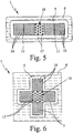
- FIGS. 7 and 8 show a fourth embodiment of the proposed device (1), namely Fig. 7 a top view of the carrier (6) without cover (7) and Fig. 8 a sectional view taken along line VIII-VIII of Fig. 7 with existing cover (7).
- the channel (3) forms here a collecting chamber (20) for the sample liquid (2).
- the collection chamber (20) is in turn substantially flat and has, if necessary, the indicated elevations (10) and / or other guide elements o. The like.
- the device (1) according to the fourth embodiment has a device (21), in particular a light guide or the like, for coupling light into the sample liquid (2), in particular for fluorescence measurements.
- the light strikes the free surface of the sample liquid (2) in the region of an open side (4) of the channel (3) and enters the sample liquid (2) due to a correspondingly steep direction of impact, preferably substantially perpendicular to the liquid surface, as indicated by arrow (22) indicated.
- the interface gas (air) / sample liquid (2) is used for the entrance of light so the interface gas (air) / sample liquid (2) is used.
- the incoming light beam (22) is preferably repeatedly reflected by total reflection at the interface sample liquid (2) / gas (air). This is achieved in that the angle betweenexcellentnlot and incident light beam is greater than the critical angle of total reflection.
- the bottom surface of the collection chamber (20) bounded and defined by the circumferential recess (5) is appropriately selected to achieve the desired beam guidance and total reflection, in the illustrative example by an appropriate polygonal configuration.
- the incident light (22) is used for fluorescence determination or fluorescence spectroscopy.
- the sample liquid (2) in particular marker molecules contained therein o. Like., Which are present for example as a chemical in channel (3) and are dissolved by sample liquid, are excited by a certain wavelength.
- the light beam plane is arranged above such or spaced apart from such structures. Furthermore, the light beam plane extends at least substantially parallel to the main extension plane or in the main extension plane E of the channel (3) or the collection chamber (20). The intended light irradiation and light guidance permit a substantially complete excitation of the sample liquid (2) or of marker molecules contained therein or the like as well as the simultaneous use of microstructures such as the elevations (10) or other guiding elements.
- Fig. 9 shows a schematic longitudinal section of a fifth embodiment of the proposed device (1).
- the filling device for filling the channel (3) between the two flat sides (8) and (9) in particular for discharging the blood plasma or the sample liquid (2) from the separating device (15) or from the top surface (9) to the opposite bottom surface (8) to form a spatial meniscus between the two faces (8) and (9), alternatively or in addition to the structures (17), a ramp (25) , which reduces the channel height H accordingly or possibly even to zero.
- the separating device (15) can be in direct contact with or rest on the ramp (25).
- the said filling device can also be called or understood as a device for lid and floor wetting.
- the schematic sectional view according to Fig. 10 shows a sixth embodiment of the proposed device (1).
- the recess (5) adjoining the channel (3) laterally can be filled by the sample liquid (2) and in such a way - in particular due to a corresponding rounding of its side wall (26) and / or through the formation of corresponding guide elements, such as elevations (10). or the like - formed such that the filling speed of the recess (5) in Haupt Stahl Ferncardi F - in the illustration according to Fig.
- the device according to the proposal (1) is suitable for a wide variety of tests, examinations or the like. In particular, it permits immunological or biochemical tests, for example of blood (19), blood plasma or the like.
- the channel (3) can form a plurality of examination areas or collecting areas (20), which can be filled successively with the sample liquid (2).
- a second examination or collection area (20) may adjoin a first examination or collection area (20), the second area preferably having a considerably higher capillarity, for example by an inserted nonwoven or the like.
- the sample liquid (2) can be subsequently sucked or guided into the second region after filling of the first region and, in particular, after dissolution of a dry chemical present there as required, wherein the dry chemical is washed out of the first region and thus, for example, a further examination in the first and / or second region is made possible.
- a first chemical in particular a dry chemical
- at least one second chemical in particular a dry chemical, preferably in the channel (3) or collecting area (20)
- the first chemical is designed such that it prevents or delays a coagulation of the blood (19).
- EDTA Ethylene Diamine Tetraacetic Acid (ethylene diamine tetraacetic acid)
- EDTA Ethylene Diamine Tetraacetic Acid (ethylene diamine tetraacetic acid)
- the second chemical serves to study or determine one or more parameters in the blood plasma, such as glucose, ketones or lactate.
- the first chemical is designed to lyse cells, such as blood cells, and liberate the calcium or the like.
- lysine buffer is used.
- the second chemical preferably a mixed chemical mixture, an investigation or determination of the parameter, in particular the calcium content.
- a component of the mixture preferably the chelating agent 8-hydroxyquinoline, is used to remove the reaction interfering magnesium ions from the reaction.
- Another complexing agent preferably o-cresolphthalein, forms a colored complex with calcium under alkaline conditions.
- the extinction of the color complex is proportional to the calcium concentration at a wavelength of 570 nm. It is determined directly in the channel (3) or collection area (20) or, if necessary, after removal.
- the extinction can also be used at other wavelengths and / or for the determination of other complexes, parameters or the like. The same applies to other, preferably optical determination methods, such as fluorescence measurements o.
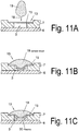
- the distance between the membrane surface and the channel bottom is the same as the channel height Fig. 11A represents.
- the separation element for blood separation can represent a fluidic barrier to the unimpeded flow of the plasma into the channel.
- a membrane or a filter element is used as the separating element, wherein the membrane or the filter element consists of an intertwined fiber network or of a porous material.
- the materials used are non-woven or compressed synthetic fibers or even porous ceramics as well as metal nets.
- the filter material has thin, branched channels with high capillary force through the mesh structure, thereby maintaining fluidic components in the filter or membrane.
- the membrane has a pore size of 0.01 microns to 1.2 microns, especially 0.2 to 0.6 microns.
- the membrane density is 50 microns to 500 microns, preferably 120 microns to 180 microns.
- the porosity that is, the volume fraction of the membrane not carried out with material, is 40-90%, preferably 70 to 80%.
- the pore material may be various materials such as nylon, in particular isotropically foamed nylon 60, with a pore volume greater than 70%, and a pore size of 0.45 micrometers, or preferably hydrophilic polyvinyl difluoride with a pore size of 0.6 micrometers.
- a drop of blood is then introduced into the inlet area in the feed device (18), a hemispherical drop of blood is applied to the surface of the membrane (15) as in FIG 11B can be observed.
- the blood plasma flows through the channels of the membrane (15), retaining the larger blood particles, and forms a plasma film or drop of plasma adhering to the membrane by the hydraulic pressure at the bottom.
- the small amounts of blood or plasma or, in particular, in the case of large dead volumes to be filled between the membrane and the channel bottom the fluidic connection between the plasma and the channel can be omitted.
- a plasma current flows in particular on the channel walls to to the channel bottom and fills the channel (3) or the collecting area (20) slowly.
- the start of the filling process is thereby delayed, which unintentionally causes long flow times, which have a negative effect on the function of a connected to the fluidic channel structure diagnostic or analytical device.
- the dead volume in the filling region between the separating element and the channel thus acts as an impedance or a resistance to the flow rate of the plasma.
- Another object solution of the present invention is to set this impedance targeted, in particular to reduce to a minimum.
- the flow resistance by an embodiment of the separating element (15) according to Fig. 11B be minimized.
- the separating element (15) is convexly shaped in the direction of the channel bottom, so that it preferably rests in a central region on the channel bottom or, alternatively, the apex of the convex shape reaches close to the channel bottom.
- the distance of the separating element, from the bottom of the filling device, in particular from the channel bottom is preferably 1 micron to 100 microns, especially 10 microns to 25 microns.
- the diameter of the membrane (15) used is 2 to 10 millimeters, in particular 250 to 350 micrometers.
- the value W is preferably 100 microns to 300 microns.
- the height value of the curvature should advantageously correspond approximately to the height of a chamber located in the inlet region or under the leading membrane (15).
- the height W of the curvature can also be adapted to the trench depth in the range of 50 to 200 microns vary.
- an element (17) is used with vertical notches on the channel bottom, as in the AP 101 3341 B1 is disclosed.
- the notch geometry initiates and supports a vertical flow from the filling area through the separating element to the channel bottom.
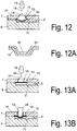
- Fig. 12 shows such elements on the channel bottom, wherein a plurality of elements are arranged to each other at the bottom of the channel, that due to the Kapillarwindung of the interstices, a horizontal volume flow of the fluid or plasma in a collection chamber (20) takes place in the channel direction.
- the convex curvature of the membrane is achieved by compressing the membrane as it is fastened in the direction of its center, causing it to bend towards the center. This can be achieved by making the diameter of the membrane larger than the diameter of the space in which the membrane attached, in particular glued.
- a corresponding holding tool (not shown), which has a convex surface shape, the membrane is inserted into the mounting area and glued. Due to the convex shaping of the tool, the shaping of the membrane deflection takes place.
- thermal methods such as welding, in particular ultrasonic welding, for fastening the membrane, wherein the membrane is advantageously also pressed in here with a preformed holding tool between two plastic elements of the device.
- the convex deflection of the separating element can also be carried out in advance by stamping the mold into the separating element.
- metallic filter elements for example, it is conceivable to press or bend them into a curved, in particular convex, shape.
- Fliesmaterialien would be a stamping process in a correspondingly shaped tool under pressure and / or temperature and / or additionally introduced chemical fixatives or adhesives conceivable.
- the separating element is constructed in two or more parts, in particular two layers, wherein a flexible membrane is arranged on a fixed holding element, in particular a membrane holder (31), such as Fig. 12A shows.
- a membrane holder 31
- the membrane is bonded in the outer region of the funnel-shaped holding element, but it can also be held by clamping elements.
- the funnel-shaped membrane holder or mold insert (29) has a passage opening or bore (32) in a central region, so that when the funnel is filled with blood, it can enter the membrane through the opening (32).
- a separating device has a membrane (15).
- the drop lies on the in Fig. 13A flat membrane (15).
- a plunger (28) inserted into the opening (14), wherein the plunger deformed the membrane surface in the direction of the channel interior, so that adjusts a convex membrane shape.
- the punch (28) is also preferably arched at its end contacting the membrane.
- the introduction of the plunger (28) can be done either manually by an operator or by an automated operating device with actuator drive means.
- the plunger (28) is mounted on an actuator, wherein the actuator moves the plunger so that it pushes down the membrane to the channel bottom.
- the actuator can be made by piezoelectric actuators or a stepper motor or other suitable mechanical or electrical actuators.
- the lowering of the plunger (28) takes place in dependence on the analysis step to be carried out.
- sensors can be attached to the device which detect the supply of a drop of blood (19) and actuate the plunger or punch (28) via a control device, in particular a microprocessor, which receives and processes the sensor signals.
- the channel (3) is formed by a recess (5) in the carrier (6) and a congruent recess in the cover (7).
- the cover (7) has an opening in the end region of the channel (3). This opening (14) is closed off to the top of the cover (7) by a pressure element (33).
- the cover element (33) comprises a punch (28) and an opening (14) through which a drop of blood (19) can be supplied to the feed region (18).
- a separating element (15) in particular a filter membrane is arranged and fixed.
- the attachment can be made for example by gluing or welding to the cover (7).
- the attachment of the membrane to the cover (7) is performed.
- the membrane-providing cover (7) and the carrier (6) are connected together.
- the cover element (33) is fastened to the cover (7), whereby the plunger (28) convexly deforms the membrane so that the dead volume in the feed device (13) is reduced and the apex of the convex membrane ( 27) reaches the vicinity of the channel bottom.
- This will be a Device (1) achieved in which a significantly reduced fluid resistance between the membrane (27) and the channel (3) is present.
- the punch (28) is inserted into a bore in the carrier (6) in the feed area.
- the stamp shank has a first section adjoining the stamp head, which in its length corresponds to the thickness of the support (6) in the region of the bore and seals the bore by inserting the stamp.
- a second section of the stamp shank is provided with notches or a profiling or has through openings in the longitudinal direction of the shaft.
- This second section of the stamp shank extends from the bottom of the feed area (18), in particular the bottom of the channel (3) or the bottom of a collection chamber (20) to the separating element (15) and contacts this, so that through the profiled stamp shank a vertical fluid connection is built up between the floor and a membrane (15).
- the stamp shaft can be provided with elevations or guide elements (10) on its preferably cylindrical lateral surface, which support a Kapillarhne the separated plasma.
- Fig. 16 shows a device in which the lid member (33) is provided with a central bore (32) through which a drop of blood (19) is introduced into the feed area (18).
- the cover element (33) is fastened to the cover (7), for example welded by means of ultrasound.
- Pressure element (33), cover (7) and carrier (6) are preferably made of plastic material.
- the membrane (27) is clamped between the cover (7) and the carrier (6), in particular welded.
- the pressure element (33) designed as a mold insert (29), wherein the mold insert (29) in the direction of the channel (3) is configured in three dimensions, the membrane is convexly bent and in fluidic contact with the bottom of the channel (3), in particular comes to the guide elements (10) at the bottom of the channel.
- the separating element (15) is first connected to the cover (7) and closes the
- the carrier element (6) which has a recess in the form of a channel (3), is constructively designed in the region of the opening of the cover (7), ie in the region of the membrane (27) just attached to the cover (7) in a region of the carrier (6) arranged opposite the central region of the opening, the carrier surface is formed beyond the connecting plane between carrier (6) and cover (7).
- This can be achieved, for example, by the fact that as in Fig. 17 provided the surface of the carrier (6) in this area convex convex, this presses against the membrane (27) and according to the shape of the carrier (6) deflects accordingly.
- the support surface is also provided in this area with guide elements (10), which cause a horizontal fluid flow of the plasma.
- the device (1) is constructed in three layers.
- the carrier (6) is connected to the cover via an intermediate element (34), in this case the channel element (34) forming the channel.
- the intermediate element (34) is adhesively bonded, for example, to the carrier (6) and to the cover (7).
- the intermediate element (34) is preferably a two-sided adhesive film.
- the channel structures, in particular the channel (3) are introduced as recesses (16) in the intermediate element, for example by punching out of the finished form or as recesses in the molding or casting process.
- the cover (7) and the carrier (6) are designed as flat elements without recesses (5) for the fluid-conducting structures, which requires the use of precise, cost-intensive microforming tools significantly reduced and makes the production easier.
- Fig. 18 is for the preparation of a fluidic contact and to reduce the flow resistance in the inlet region of the channel provided to form the carrier element (6) in the direction of the membrane (27), in particular at least one pin (37) in the carrier element (6) to bring in from the connection plane between the channel element (34) and the support element (6) protrudes in the direction of the membrane and makes a fluidic contact with the membrane.
- the pin (37), for example, in the production of the carrier (6) can be introduced directly by molding or downstream by mechanical and / or thermal impressions in the carrier element.
- the channel (3) as a recess (5) in the carriers (6) is formed.
- the separating device (15) in this case a filter element (15), is arranged in a recess (16) of the cover (7) and together with the insert element or insert (35) forms the tension guiding device (13). If a drop (19) of blood is now supplied to the feed region (18), the blood is absorbed by the filter (15) and filtered, the plasma exiting in the channel direction being taken up by the insert (35) arranged on the channel side of the filter (15) becomes.
- the insert (35) is geometrically designed such that its height corresponds approximately to the height of the space between the channel bottom and the underside of the filter (15) and the insert (35) both the channel bottom or chamber bottom in the inlet region as well as the bottom of the filter contacted.
- the insert (35) is an insert element (35), which means that the insert (35) when mounting the carrier (6) with the cover (7) its attachment learns by the fact that he from the contact pressure between the filter and the carrier (6) is held.
- the insert can be made for example as an O-ring made of an elastic plastic or a rubber.
- this consists of a further filter material, this may be a porous ceramic, a sponge made of fiber material, a metallic mesh or mesh element or any other suitable element of channel-carrying structures.
- the insert (35) is designed as a horseshoe-shaped insert element (35).
- the insert element can be made of non-porous Plastic material, but it is also conceivable to produce the insert element of one of the above channel-carrying materials.
- the insertion element in the edge region at least one notch (36), in particular a plurality of notches (36), which support a vertical discharge of the plasma into the plasma chamber (20) or the channel (3).
- the cross section of the inserts is wedge-shaped, as the section AA in Fig. 19A shows, wherein the tip of the wedge contacts the membrane surface and thereby establishes the fluid contact.
- the air present in the volume of the feed region can be enclosed in the filling region by means of a drop of blood during the filling.
- a cover (7) and an intermediate element (34) In order to ensure that in a structure with a carrier (6), a cover (7) and an intermediate element (34), a tight seal of the filter (15) is achieved, this is provided in its mounting region with a pressure (38), which compresses the filter material in the area of the pressure (38).
- a pressure (38) which compresses the filter material in the area of the pressure (38).
- Fig. 21 is in a support member (6) a recess (5) formed, which forms the channel (3).
- the intermediate element is a film-like plastic part provided with an adhesive on both sides, the adhesive making contact by gluing both to the cover (7) and to the carrier (6) and connecting them together.
- an insert (35) in the form of an insert (35) is arranged in the region of the feed device.
- the separator or the filter (15) is glued or welded into the cover (7), wherein the welding takes place for example by means of ultrasound or by means of thermal welding.
- the feed area is shown from above.
- the intermediate element (34) can be seen, which is, for example, a channel element with punched holes which form a sample collection chamber (20) in the feed region and a channel (3).
- the guide elements (10) can be seen in the region of the sample chamber (20).
- the welding line (fixing line) (39) is schematically illustrated, which in the upper cover (7) prevents the filter or the filter membrane (15) with the cover.
- the intermediate element is in particular a film which is provided on both sides with an adhesive.
- the separated plasma flows into the collection chamber (20) and is derived by the guide elements supportive in the channel (3).
- the inlet region of the channel (3) represents a clear and abrupt reduction of the flow cross-section.
- Fig. 22A shows, it can come to the influx of air into the channel (3), whereby flowing air bubbles can get into the channel, which can significantly increase the flow resistance or bring the flow flow completely to a standstill.
- the transverse inflow of air (40) since the filter material by the compression at this point during welding leaves a cavity from which air can flow.
- Fig. 23 provided to continuously reduce the flow area from the collection chamber to the channel along a transition region. This can be done, for example step by step, by like FIG. 22 can be seen, first a reduction in the cross-sectional area is carried out so far that the reduced cross section (41) is about 2 to 5 times the cross section of the channel (3).
- the cross-sectional step (41) is arranged such that the circumferential attachment line (39) brakes the outlet region from the collection chamber (20) in the region of the cross-sectional step and forms no intersection with the channel (3), whereby a direct inflow of air (40) in the channel (3) is avoided.
- These vanes help to support wetting by vertical fluid flow.
- a horizontal fluid flow is also supported by the capillary-acting intermediate spaces between the guide elements (10).
- All these embodiments have in common that the guide elements are not an essential functional component.
- a guide element (10) and the respective existing capillary gap between a filter and or a membrane (15) and the bottom of a channel (3) or a feed device (18) as influenced by the curvature of the soil to the membrane wedge-shaped capillary gaps with low height and high capillarity can be set in the contact surfaces or the nutritional surfaces.
Landscapes
- Chemical & Material Sciences (AREA)
- Health & Medical Sciences (AREA)
- Life Sciences & Earth Sciences (AREA)
- Chemical Kinetics & Catalysis (AREA)
- Hematology (AREA)
- Engineering & Computer Science (AREA)
- Analytical Chemistry (AREA)
- General Health & Medical Sciences (AREA)
- Biomedical Technology (AREA)
- Dispersion Chemistry (AREA)
- Molecular Biology (AREA)
- Clinical Laboratory Science (AREA)
- Physics & Mathematics (AREA)
- Food Science & Technology (AREA)
- Medicinal Chemistry (AREA)
- Biochemistry (AREA)
- Urology & Nephrology (AREA)
- General Physics & Mathematics (AREA)
- Immunology (AREA)
- Pathology (AREA)
- Biophysics (AREA)
- Ecology (AREA)
- Investigating Or Analysing Biological Materials (AREA)
- Sampling And Sample Adjustment (AREA)
- External Artificial Organs (AREA)
Applications Claiming Priority (2)
| Application Number | Priority Date | Filing Date | Title |
|---|---|---|---|
| DE102008011339 | 2008-02-27 | ||
| PCT/EP2009/001383 WO2009106331A2 (de) | 2008-02-27 | 2009-02-26 | Vorrichtung zur plasmaseparation |
Publications (2)
| Publication Number | Publication Date |
|---|---|
| EP2268405A2 EP2268405A2 (de) | 2011-01-05 |
| EP2268405B1 true EP2268405B1 (de) | 2017-01-04 |
Family
ID=40640360
Family Applications (1)
| Application Number | Title | Priority Date | Filing Date |
|---|---|---|---|
| EP09714713.6A Active EP2268405B1 (de) | 2008-02-27 | 2009-02-26 | Vorrichtung zur plasmaseparation |
Country Status (10)
| Country | Link |
|---|---|
| US (2) | US9539572B2 (enExample) |
| EP (1) | EP2268405B1 (enExample) |
| JP (1) | JP5475692B2 (enExample) |
| CN (1) | CN101959602A (enExample) |
| AU (1) | AU2009218752B2 (enExample) |
| BR (1) | BRPI0907148B1 (enExample) |
| CA (1) | CA2716411C (enExample) |
| MX (1) | MX346456B (enExample) |
| RU (1) | RU2523681C2 (enExample) |
| WO (1) | WO2009106331A2 (enExample) |
Families Citing this family (48)
| Publication number | Priority date | Publication date | Assignee | Title |
|---|---|---|---|---|
| FR2950544B1 (fr) * | 2009-09-29 | 2011-12-09 | Ecole Polytech | Circuit microfluidique |
| US8496889B2 (en) * | 2010-03-23 | 2013-07-30 | California Institute Of Technology | Microfluidic device for separating and sorting particles in a fluid medium |
| EP2413138B1 (de) * | 2010-07-27 | 2020-04-29 | BOEHRINGER INGELHEIM microParts GmbH | Vorrichtung und verfahren zur abtrennung von bestandteilen einer probenflüssigkeit |
| JP5850373B2 (ja) | 2010-07-27 | 2016-02-03 | ベーリンガー インゲルハイム マイクロパーツ ゲゼルシャフト ミットベシュレンクテル ハフツングBoehringer Ingelheim microParts GmbH | サンプル液体の成分を分離する器具及び方法 |
| US9116089B2 (en) | 2010-11-10 | 2015-08-25 | Boehringer Ingelheim Microparts Gmbh | Device for filtering blood |
| EP2688672A2 (de) | 2011-03-24 | 2014-01-29 | Boehringer Ingelheim Microparts GmbH | Vorrichtung und verfahren zur filtration von blut |
| US20130084647A1 (en) * | 2011-09-30 | 2013-04-04 | Michael W. LaCourt | Disposable foil punch for immunohematology test elements |
| US9386948B2 (en) | 2012-12-05 | 2016-07-12 | Theranos, Inc. | Systems, devices, and methods for bodily fluid sample transport |
| US10248765B1 (en) | 2012-12-05 | 2019-04-02 | Theranos Ip Company, Llc | Systems, devices, and methods for bodily fluid sample collection, transport, and handling |
| JP2014173937A (ja) * | 2013-03-07 | 2014-09-22 | Toshiba Corp | 半導体マイクロ分析チップ及び検体流動方法 |
| EP2972184A4 (en) | 2013-03-15 | 2016-11-30 | Theranos Inc | Methods and devices for sample collection and sample separation |
| US20140323911A1 (en) * | 2013-03-15 | 2014-10-30 | Theranos, Inc. | Methods and devices for sample collection and sample separation |
| ES2539843B2 (es) * | 2013-11-15 | 2015-11-16 | Universitat Politècnica De Catalunya | Dispositivo microfluídico para la separación de líquido del mismo líquido conteniendo partículas deformables sin fuentes de energía externas |
| JP6566319B2 (ja) * | 2013-12-03 | 2019-08-28 | 国立大学法人 東京大学 | 分離ユニット、分離方法、流体デバイス、複合型流体デバイス及びキット |
| WO2015095491A1 (en) * | 2013-12-19 | 2015-06-25 | The Trustees Of The University Of Pennsylvania | Plasma separator apparatus and associated methods |
| CA2953755C (en) * | 2014-07-03 | 2022-05-03 | Abionic Sa | Capsule for rapid molecular quantification of a fluid sample such as whole blood |
| US10071373B2 (en) | 2014-08-08 | 2018-09-11 | Ortho-Clinical Diagnostics, Inc. | Lateral-flow assay device having flow constrictions |
| US11033896B2 (en) | 2014-08-08 | 2021-06-15 | Ortho-Clinical Diagnostics, Inc. | Lateral-flow assay device with filtration flow control |
| US10073091B2 (en) * | 2014-08-08 | 2018-09-11 | Ortho-Clinical Diagnostics, Inc. | Lateral flow assay device |
| CN107108199B (zh) * | 2014-11-11 | 2020-01-10 | 微研生物科技有限公司 | 用于研究基于细胞的相互作用的微流体平台 |
| US10690653B2 (en) | 2014-12-12 | 2020-06-23 | The Trustees Of The University Of Pennsylvania | Fluid separator for point of care molecular diagnostics |
| US10829804B2 (en) | 2015-03-23 | 2020-11-10 | The University Of North Carolina At Chapel Hill | Method for identification and enumeration of nucleic acid sequences, expression, splice variant, translocation, copy, or DNA methylation changes using combined nuclease, ligase, polymerase, terminal transferase, and sequencing reactions |
| EP3274091B1 (en) * | 2015-03-23 | 2020-12-02 | The University of North Carolina at Chapel Hill | Universal molecular processor for precision medicine |
| CA2989764C (en) | 2015-06-20 | 2021-11-30 | Goran Stemme | A plasma separating microfluidic device |
| WO2016208362A1 (ja) * | 2015-06-22 | 2016-12-29 | 株式会社村田製作所 | 濾過フィルター |
| US10371606B2 (en) | 2015-07-21 | 2019-08-06 | Theraos IP Company, LLC | Bodily fluid sample collection and transport |
| WO2017044888A1 (en) | 2015-09-09 | 2017-03-16 | Theranos, Inc. | Methods and devices for sample collection and sample separation |
| US10730044B2 (en) | 2015-10-01 | 2020-08-04 | The Regents Of The University Of Michigan | Assay plate and uses thereof |
| US10369567B2 (en) * | 2015-11-04 | 2019-08-06 | International Business Machines Corporation | Continuous, capacitance-based monitoring of liquid flows in a microfluidic device |
| WO2017210199A1 (en) | 2016-05-31 | 2017-12-07 | Oregon State University | Fluidic devices for chromatographic separation and methods of making and using the same |
| CN116747613B (zh) * | 2016-06-07 | 2024-07-19 | 苏州苏瑞膜纳米科技有限公司 | 流体处理装置及其制备方法 |
| JP6729026B2 (ja) * | 2016-06-15 | 2020-07-22 | ウシオ電機株式会社 | マイクロ流路チップおよび検体濃度測定装置 |
| KR101891401B1 (ko) * | 2016-08-12 | 2018-08-23 | 고려대학교 산학협력단 | 미세유체 소자 및 이의 제조방법 |
| RU175245U1 (ru) * | 2017-01-13 | 2017-11-28 | Сергей Викторович Минаев | Сепарационное устройство для определения биохимических показателей и маркеров заболеваний в плазме крови |
| US11857966B1 (en) | 2017-03-15 | 2024-01-02 | Labrador Diagnostics Llc | Methods and devices for sample collection and sample separation |
| CN108722504A (zh) * | 2017-04-19 | 2018-11-02 | 光宝电子(广州)有限公司 | 检测装置及其注入口结构 |
| JP6877745B2 (ja) * | 2017-06-08 | 2021-05-26 | セルスペクト株式会社 | 血漿分離装置及び血漿分離方法 |
| TWI651074B (zh) * | 2017-10-25 | 2019-02-21 | 台達電子工業股份有限公司 | 粒子凝集混合方法及混合設備 |
| US11207455B2 (en) * | 2018-05-14 | 2021-12-28 | Oregon State University | Membrane device for blood separation and methods of making and using the same |
| JP2019209238A (ja) * | 2018-05-31 | 2019-12-12 | 日東電工株式会社 | 血液濾過膜 |
| CA3103453A1 (en) * | 2018-06-12 | 2019-12-19 | Nowdiagnostics, Inc. | Device and method for collecting plasma |
| US12326445B2 (en) | 2018-08-31 | 2025-06-10 | National Institute Of Advanced Industrial Science And Technology | Assay device |
| JP7409693B2 (ja) | 2018-09-06 | 2024-01-09 | キャピテイナー アーベー | マイクロ流体装置 |
| US10422729B1 (en) | 2019-03-08 | 2019-09-24 | Biodesix, Inc. | Blood sample separation devices and methods |
| US20220212474A1 (en) * | 2019-04-25 | 2022-07-07 | Kyocera Corporation | Flow path device, cartridge, and measurement system |
| CN120361622A (zh) * | 2019-10-02 | 2025-07-25 | 奥斯龙-明士克公司 | 血液成分收集和分离介质、血液成分收集和分离装置以及血液成分分离和提取方法 |
| CN113828028A (zh) * | 2021-10-31 | 2021-12-24 | 康硕(江西)智能制造有限公司 | 一种可更换滤网3d打印用陶瓷浆料过滤器 |
| US20250325986A1 (en) * | 2022-06-23 | 2025-10-23 | Solventum Intellectual Properties Company | Methods and devices for removing particles from fluids |
Family Cites Families (26)
| Publication number | Priority date | Publication date | Assignee | Title |
|---|---|---|---|---|
| US4323536A (en) | 1980-02-06 | 1982-04-06 | Eastman Kodak Company | Multi-analyte test device |
| JPH06103300B2 (ja) | 1986-03-25 | 1994-12-14 | ピービー ダイアグノスティック システムズ,インコーポレーテッド | 生物学的診断装置 |
| US6767510B1 (en) | 1992-05-21 | 2004-07-27 | Biosite, Inc. | Diagnostic devices and apparatus for the controlled movement of reagents without membranes |
| US6156270A (en) * | 1992-05-21 | 2000-12-05 | Biosite Diagnostics, Inc. | Diagnostic devices and apparatus for the controlled movement of reagents without membranes |
| US5458852A (en) | 1992-05-21 | 1995-10-17 | Biosite Diagnostics, Inc. | Diagnostic devices for the controlled movement of reagents without membranes |
| GB9324310D0 (en) * | 1993-11-26 | 1994-01-12 | Univ Birmingham | Liquid transfer device |
| US5756129A (en) * | 1994-07-01 | 1998-05-26 | Kabushiki Kaisha Kobe Seiko Sho | Filter member and screen changer for use in resin extruder |
| US5733449A (en) * | 1995-12-08 | 1998-03-31 | Orbital Biosciences, Llc | Microconcentrator device |
| US5922604A (en) * | 1997-06-05 | 1999-07-13 | Gene Tec Corporation | Thin reaction chambers for containing and handling liquid microvolumes |
| DE19753849A1 (de) | 1997-12-04 | 1999-06-10 | Roche Diagnostics Gmbh | Analytisches Testelement mit sich verjüngendem Kapillarkanal |
| WO2001024931A1 (en) | 1999-10-05 | 2001-04-12 | Roche Diagnostic Gmbh | Capillary device for separating undesired components from a liquid sample and related method |
| AU2001274558A1 (en) * | 2000-06-20 | 2002-01-02 | Kawamura Institute Of Chemical Research | Microdevice having multilayer structure and method for fabricating the same |
| DK1201304T3 (da) | 2000-10-25 | 2006-11-13 | Boehringer Ingelheim Micropart | Mikrostruktureret platform til undersögelse af en væske |
| US6776294B2 (en) * | 2000-12-18 | 2004-08-17 | Millipore Corporation | Device for microbiological examination of a sample of liquid under pressure and method for draining this device |
| AU2002352746A1 (en) * | 2001-11-15 | 2003-06-10 | Arryx, Inc. | Sample chip |
| SE0201738D0 (sv) | 2002-06-07 | 2002-06-07 | Aamic Ab | Micro-fluid structures |
| DE10326607A1 (de) * | 2003-06-13 | 2005-01-05 | Steag Microparts Gmbh | Vorrichtung zum Handhaben von Flüssigkeiten |
| US20040265171A1 (en) * | 2003-06-27 | 2004-12-30 | Pugia Michael J. | Method for uniform application of fluid into a reactive reagent area |
| US6938526B2 (en) * | 2003-07-30 | 2005-09-06 | Black & Decker Inc. | Impact wrench having an improved anvil to square driver transition |
| KR20060079791A (ko) * | 2003-08-08 | 2006-07-06 | 마이크롤리스 코포레이션 | 단순형 필터 장치 |
| DE10352535A1 (de) * | 2003-11-07 | 2005-06-16 | Steag Microparts Gmbh | Mikrostrukturierte Trennvorrichtung und Verfahren zum Abtrennen von flüssigen Bestandteilen aus einer Partikel enthaltenden Flüssigkeit |
| DE10360220A1 (de) * | 2003-12-20 | 2005-07-21 | Steag Microparts Gmbh | Mikrostrukturierte Anordnung zur blasenfreien Befüllung zumindest eines Systems zur Ableitung von Flüssigkeiten, Vorrichtung mit einer solchen Anordnung und Befüllungsverfahren |
| DE102004027422A1 (de) * | 2004-06-04 | 2005-12-29 | Boehringer Ingelheim Microparts Gmbh | Vorrichtung zur Aufnahme von Blut und Abtrennung von Blutbestandteilen |
| EP1685900B1 (de) * | 2005-01-27 | 2011-03-30 | Boehringer Ingelheim microParts GmbH | Verwendung einer Vorrichtung zur Untersuchung von Probenflüssigkeit |
| DE102005017653A1 (de) * | 2005-04-15 | 2006-10-19 | Boehringer Ingelheim Microparts Gmbh | Vorrichtung und Verfahren zur Manipulation einer Flüssigkeit |
| US7344465B2 (en) * | 2005-07-28 | 2008-03-18 | Caterpillar Inc. | Drive system for a machine |
-
2009
- 2009-02-26 BR BRPI0907148-2A patent/BRPI0907148B1/pt active IP Right Grant
- 2009-02-26 EP EP09714713.6A patent/EP2268405B1/de active Active
- 2009-02-26 WO PCT/EP2009/001383 patent/WO2009106331A2/de not_active Ceased
- 2009-02-26 AU AU2009218752A patent/AU2009218752B2/en active Active
- 2009-02-26 RU RU2010139578/14A patent/RU2523681C2/ru active
- 2009-02-26 US US12/867,335 patent/US9539572B2/en active Active
- 2009-02-26 CN CN200980106816XA patent/CN101959602A/zh active Pending
- 2009-02-26 JP JP2010548023A patent/JP5475692B2/ja active Active
- 2009-02-26 MX MX2010009331A patent/MX346456B/es active IP Right Grant
- 2009-02-26 CA CA2716411A patent/CA2716411C/en active Active
-
2016
- 2016-11-22 US US15/358,185 patent/US10363559B2/en active Active
Non-Patent Citations (1)
| Title |
|---|
| None * |
Also Published As
| Publication number | Publication date |
|---|---|
| BRPI0907148B1 (pt) | 2021-01-12 |
| CA2716411A1 (en) | 2009-09-03 |
| EP2268405A2 (de) | 2011-01-05 |
| CN101959602A (zh) | 2011-01-26 |
| US20110011781A1 (en) | 2011-01-20 |
| CA2716411C (en) | 2015-11-24 |
| RU2010139578A (ru) | 2012-04-10 |
| WO2009106331A3 (de) | 2010-02-25 |
| US10363559B2 (en) | 2019-07-30 |
| JP5475692B2 (ja) | 2014-04-16 |
| AU2009218752B2 (en) | 2014-07-10 |
| US9539572B2 (en) | 2017-01-10 |
| BRPI0907148A2 (pt) | 2020-08-25 |
| WO2009106331A2 (de) | 2009-09-03 |
| MX346456B (es) | 2017-03-21 |
| JP2011513718A (ja) | 2011-04-28 |
| RU2523681C2 (ru) | 2014-07-20 |
| WO2009106331A4 (de) | 2010-04-22 |
| AU2009218752A1 (en) | 2009-09-03 |
| US20170165666A1 (en) | 2017-06-15 |
| MX2010009331A (es) | 2010-09-14 |
Similar Documents
| Publication | Publication Date | Title |
|---|---|---|
| EP2268405B1 (de) | Vorrichtung zur plasmaseparation | |
| EP1761757B1 (de) | Vorrichtung zur aufnahme von blut und abtrennung von blutbestandteilen, sowie verwendungen der vorrictung | |
| EP0949002B1 (de) | Verfahren zur Herstellung von analytischen Hilfsmitteln | |
| DE102011078961B4 (de) | System zum Separieren von Körperflüssigkeitsbestandteilen und Verfahren zum Herstellen eines derartigen Systems | |
| EP2560756B1 (de) | Vorrichtung zur plasmaseparation mittels einer zentralen kanalstruktur | |
| EP1522343B1 (de) | Analytisches Testelement umfassend ein hydrophiles Netzwerk zur Bildung eines Kapillarkanals, dessen Verwendung und Verfahren zur Bestimmung eines Analyten in einer Flüssigkeit | |
| EP1013341B1 (de) | Vorrichtung zum Ableiten einer Flüssigkeit aus Kapillaren | |
| EP2687290B1 (de) | Mikrofluidische Lagerungsvorrichtung zum Vorlagern eines Fluids, Verfahren zu dessen Herstellung und eine Verwendung derselben | |
| EP3049186B1 (de) | Analyseeinheit zum durchführen einer polymerasekettenreaktion, verfahren zum betreiben einer solchen analyseeinheit und verfahren zum herstellen einer solchen analyseeinheit | |
| WO1999046045A1 (de) | Probenträger | |
| EP1685900B1 (de) | Verwendung einer Vorrichtung zur Untersuchung von Probenflüssigkeit | |
| DE112017004280B4 (de) | Mikrofluidik-Chip mit Perlenintegrationssystem | |
| DE602004005681T2 (de) | Kapillarsperre | |
| EP2552586B1 (de) | Bauteil eines biosensors und verfahren zur herstellung | |
| EP1843833B1 (de) | Verfahren und vorrichtung zur dosierung und durchmischung kleiner flüssigkeitsmengen, apparat und verwendung | |
| EP1534432B1 (de) | Mikrofluidische systeme mit hohem aspektverhä ltnis | |
| EP1833598B1 (de) | Verfahren und vorrichtung zur dosierung und durchmischung kleiner flüssigkeitsmengen | |
| DE102005000834B4 (de) | Verfahren und Vorrichtung zur Dosierung und Durchmischung kleiner Flüssigkeitsmengen | |
| WO2012019829A1 (de) | Vorrichtung und verfahren zur abtrennung von bestandteilen einer probenflüssigkeit | |
| DE102006049560A1 (de) | Trägerelement und Verfahren zur Herstellung desselben | |
| WO2011048200A2 (de) | Mikrokapillarsystem mit erhöhtem probenvolumen |
Legal Events
| Date | Code | Title | Description |
|---|---|---|---|
| PUAI | Public reference made under article 153(3) epc to a published international application that has entered the european phase |
Free format text: ORIGINAL CODE: 0009012 |
|
| 17P | Request for examination filed |
Effective date: 20100927 |
|
| AK | Designated contracting states |
Kind code of ref document: A2 Designated state(s): AT BE BG CH CY CZ DE DK EE ES FI FR GB GR HR HU IE IS IT LI LT LU LV MC MK MT NL NO PL PT RO SE SI SK TR |
|
| AX | Request for extension of the european patent |
Extension state: AL BA RS |
|
| DAX | Request for extension of the european patent (deleted) | ||
| 17Q | First examination report despatched |
Effective date: 20121102 |
|
| REG | Reference to a national code |
Ref country code: DE Ref legal event code: R079 Ref document number: 502009013541 Country of ref document: DE Free format text: PREVIOUS MAIN CLASS: B01L0003000000 Ipc: G01N0033490000 |
|
| RIC1 | Information provided on ipc code assigned before grant |
Ipc: B01L 3/00 20060101ALI20160722BHEP Ipc: G01N 33/49 20060101AFI20160722BHEP |
|
| GRAP | Despatch of communication of intention to grant a patent |
Free format text: ORIGINAL CODE: EPIDOSNIGR1 |
|
| INTG | Intention to grant announced |
Effective date: 20160907 |
|
| GRAS | Grant fee paid |
Free format text: ORIGINAL CODE: EPIDOSNIGR3 |
|
| GRAA | (expected) grant |
Free format text: ORIGINAL CODE: 0009210 |
|
| AK | Designated contracting states |
Kind code of ref document: B1 Designated state(s): AT BE BG CH CY CZ DE DK EE ES FI FR GB GR HR HU IE IS IT LI LT LU LV MC MK MT NL NO PL PT RO SE SI SK TR |
|
| REG | Reference to a national code |
Ref country code: GB Ref legal event code: FG4D Free format text: NOT ENGLISH |
|
| REG | Reference to a national code |
Ref country code: CH Ref legal event code: EP |
|
| REG | Reference to a national code |
Ref country code: AT Ref legal event code: REF Ref document number: 859741 Country of ref document: AT Kind code of ref document: T Effective date: 20170115 |
|
| REG | Reference to a national code |
Ref country code: IE Ref legal event code: FG4D Free format text: LANGUAGE OF EP DOCUMENT: GERMAN |
|
| REG | Reference to a national code |
Ref country code: DE Ref legal event code: R096 Ref document number: 502009013541 Country of ref document: DE |
|
| REG | Reference to a national code |
Ref country code: FR Ref legal event code: PLFP Year of fee payment: 9 |
|
| REG | Reference to a national code |
Ref country code: NL Ref legal event code: FP |
|
| REG | Reference to a national code |
Ref country code: LT Ref legal event code: MG4D |
|
| PG25 | Lapsed in a contracting state [announced via postgrant information from national office to epo] |
Ref country code: BE Free format text: LAPSE BECAUSE OF NON-PAYMENT OF DUE FEES Effective date: 20170228 |
|
| PG25 | Lapsed in a contracting state [announced via postgrant information from national office to epo] |
Ref country code: LT Free format text: LAPSE BECAUSE OF FAILURE TO SUBMIT A TRANSLATION OF THE DESCRIPTION OR TO PAY THE FEE WITHIN THE PRESCRIBED TIME-LIMIT Effective date: 20170104 Ref country code: FI Free format text: LAPSE BECAUSE OF FAILURE TO SUBMIT A TRANSLATION OF THE DESCRIPTION OR TO PAY THE FEE WITHIN THE PRESCRIBED TIME-LIMIT Effective date: 20170104 Ref country code: GR Free format text: LAPSE BECAUSE OF FAILURE TO SUBMIT A TRANSLATION OF THE DESCRIPTION OR TO PAY THE FEE WITHIN THE PRESCRIBED TIME-LIMIT Effective date: 20170405 Ref country code: NO Free format text: LAPSE BECAUSE OF FAILURE TO SUBMIT A TRANSLATION OF THE DESCRIPTION OR TO PAY THE FEE WITHIN THE PRESCRIBED TIME-LIMIT Effective date: 20170404 Ref country code: IS Free format text: LAPSE BECAUSE OF FAILURE TO SUBMIT A TRANSLATION OF THE DESCRIPTION OR TO PAY THE FEE WITHIN THE PRESCRIBED TIME-LIMIT Effective date: 20170504 Ref country code: HR Free format text: LAPSE BECAUSE OF FAILURE TO SUBMIT A TRANSLATION OF THE DESCRIPTION OR TO PAY THE FEE WITHIN THE PRESCRIBED TIME-LIMIT Effective date: 20170104 |
|
| PG25 | Lapsed in a contracting state [announced via postgrant information from national office to epo] |
Ref country code: LV Free format text: LAPSE BECAUSE OF FAILURE TO SUBMIT A TRANSLATION OF THE DESCRIPTION OR TO PAY THE FEE WITHIN THE PRESCRIBED TIME-LIMIT Effective date: 20170104 Ref country code: PT Free format text: LAPSE BECAUSE OF FAILURE TO SUBMIT A TRANSLATION OF THE DESCRIPTION OR TO PAY THE FEE WITHIN THE PRESCRIBED TIME-LIMIT Effective date: 20170504 Ref country code: PL Free format text: LAPSE BECAUSE OF FAILURE TO SUBMIT A TRANSLATION OF THE DESCRIPTION OR TO PAY THE FEE WITHIN THE PRESCRIBED TIME-LIMIT Effective date: 20170104 Ref country code: ES Free format text: LAPSE BECAUSE OF FAILURE TO SUBMIT A TRANSLATION OF THE DESCRIPTION OR TO PAY THE FEE WITHIN THE PRESCRIBED TIME-LIMIT Effective date: 20170104 Ref country code: SE Free format text: LAPSE BECAUSE OF FAILURE TO SUBMIT A TRANSLATION OF THE DESCRIPTION OR TO PAY THE FEE WITHIN THE PRESCRIBED TIME-LIMIT Effective date: 20170104 Ref country code: BG Free format text: LAPSE BECAUSE OF FAILURE TO SUBMIT A TRANSLATION OF THE DESCRIPTION OR TO PAY THE FEE WITHIN THE PRESCRIBED TIME-LIMIT Effective date: 20170404 |
|
| REG | Reference to a national code |
Ref country code: CH Ref legal event code: PL |
|
| REG | Reference to a national code |
Ref country code: DE Ref legal event code: R097 Ref document number: 502009013541 Country of ref document: DE |
|
| PG25 | Lapsed in a contracting state [announced via postgrant information from national office to epo] |
Ref country code: RO Free format text: LAPSE BECAUSE OF FAILURE TO SUBMIT A TRANSLATION OF THE DESCRIPTION OR TO PAY THE FEE WITHIN THE PRESCRIBED TIME-LIMIT Effective date: 20170104 Ref country code: EE Free format text: LAPSE BECAUSE OF FAILURE TO SUBMIT A TRANSLATION OF THE DESCRIPTION OR TO PAY THE FEE WITHIN THE PRESCRIBED TIME-LIMIT Effective date: 20170104 Ref country code: SK Free format text: LAPSE BECAUSE OF FAILURE TO SUBMIT A TRANSLATION OF THE DESCRIPTION OR TO PAY THE FEE WITHIN THE PRESCRIBED TIME-LIMIT Effective date: 20170104 Ref country code: CZ Free format text: LAPSE BECAUSE OF FAILURE TO SUBMIT A TRANSLATION OF THE DESCRIPTION OR TO PAY THE FEE WITHIN THE PRESCRIBED TIME-LIMIT Effective date: 20170104 Ref country code: LI Free format text: LAPSE BECAUSE OF NON-PAYMENT OF DUE FEES Effective date: 20170228 Ref country code: IT Free format text: LAPSE BECAUSE OF FAILURE TO SUBMIT A TRANSLATION OF THE DESCRIPTION OR TO PAY THE FEE WITHIN THE PRESCRIBED TIME-LIMIT Effective date: 20170104 Ref country code: CH Free format text: LAPSE BECAUSE OF NON-PAYMENT OF DUE FEES Effective date: 20170228 |
|
| PLBE | No opposition filed within time limit |
Free format text: ORIGINAL CODE: 0009261 |
|
| STAA | Information on the status of an ep patent application or granted ep patent |
Free format text: STATUS: NO OPPOSITION FILED WITHIN TIME LIMIT |
|
| REG | Reference to a national code |
Ref country code: IE Ref legal event code: MM4A |
|
| PG25 | Lapsed in a contracting state [announced via postgrant information from national office to epo] |
Ref country code: DK Free format text: LAPSE BECAUSE OF FAILURE TO SUBMIT A TRANSLATION OF THE DESCRIPTION OR TO PAY THE FEE WITHIN THE PRESCRIBED TIME-LIMIT Effective date: 20170104 Ref country code: MC Free format text: LAPSE BECAUSE OF FAILURE TO SUBMIT A TRANSLATION OF THE DESCRIPTION OR TO PAY THE FEE WITHIN THE PRESCRIBED TIME-LIMIT Effective date: 20170104 |
|
| 26N | No opposition filed |
Effective date: 20171005 |
|
| PG25 | Lapsed in a contracting state [announced via postgrant information from national office to epo] |
Ref country code: LU Free format text: LAPSE BECAUSE OF NON-PAYMENT OF DUE FEES Effective date: 20170226 |
|
| REG | Reference to a national code |
Ref country code: BE Ref legal event code: MM Effective date: 20170228 |
|
| REG | Reference to a national code |
Ref country code: FR Ref legal event code: PLFP Year of fee payment: 10 |
|
| PG25 | Lapsed in a contracting state [announced via postgrant information from national office to epo] |
Ref country code: IE Free format text: LAPSE BECAUSE OF NON-PAYMENT OF DUE FEES Effective date: 20170226 Ref country code: SI Free format text: LAPSE BECAUSE OF FAILURE TO SUBMIT A TRANSLATION OF THE DESCRIPTION OR TO PAY THE FEE WITHIN THE PRESCRIBED TIME-LIMIT Effective date: 20170104 |
|
| REG | Reference to a national code |
Ref country code: AT Ref legal event code: MM01 Ref document number: 859741 Country of ref document: AT Kind code of ref document: T Effective date: 20170226 |
|
| PG25 | Lapsed in a contracting state [announced via postgrant information from national office to epo] |
Ref country code: AT Free format text: LAPSE BECAUSE OF NON-PAYMENT OF DUE FEES Effective date: 20170226 |
|
| PG25 | Lapsed in a contracting state [announced via postgrant information from national office to epo] |
Ref country code: MT Free format text: LAPSE BECAUSE OF FAILURE TO SUBMIT A TRANSLATION OF THE DESCRIPTION OR TO PAY THE FEE WITHIN THE PRESCRIBED TIME-LIMIT Effective date: 20170104 |
|
| PG25 | Lapsed in a contracting state [announced via postgrant information from national office to epo] |
Ref country code: HU Free format text: LAPSE BECAUSE OF FAILURE TO SUBMIT A TRANSLATION OF THE DESCRIPTION OR TO PAY THE FEE WITHIN THE PRESCRIBED TIME-LIMIT; INVALID AB INITIO Effective date: 20090226 |
|
| PG25 | Lapsed in a contracting state [announced via postgrant information from national office to epo] |
Ref country code: CY Free format text: LAPSE BECAUSE OF NON-PAYMENT OF DUE FEES Effective date: 20170104 |
|
| PG25 | Lapsed in a contracting state [announced via postgrant information from national office to epo] |
Ref country code: MK Free format text: LAPSE BECAUSE OF FAILURE TO SUBMIT A TRANSLATION OF THE DESCRIPTION OR TO PAY THE FEE WITHIN THE PRESCRIBED TIME-LIMIT Effective date: 20170104 |
|
| PG25 | Lapsed in a contracting state [announced via postgrant information from national office to epo] |
Ref country code: TR Free format text: LAPSE BECAUSE OF FAILURE TO SUBMIT A TRANSLATION OF THE DESCRIPTION OR TO PAY THE FEE WITHIN THE PRESCRIBED TIME-LIMIT Effective date: 20170104 |
|
| PGFP | Annual fee paid to national office [announced via postgrant information from national office to epo] |
Ref country code: NL Payment date: 20250218 Year of fee payment: 17 |
|
| PGFP | Annual fee paid to national office [announced via postgrant information from national office to epo] |
Ref country code: DE Payment date: 20250218 Year of fee payment: 17 |
|
| PGFP | Annual fee paid to national office [announced via postgrant information from national office to epo] |
Ref country code: FR Payment date: 20250221 Year of fee payment: 17 |
|
| PGFP | Annual fee paid to national office [announced via postgrant information from national office to epo] |
Ref country code: GB Payment date: 20250219 Year of fee payment: 17 |