EP2268405B1 - Apparatus for the separation of plasma - Google Patents
Apparatus for the separation of plasma Download PDFInfo
- Publication number
- EP2268405B1 EP2268405B1 EP09714713.6A EP09714713A EP2268405B1 EP 2268405 B1 EP2268405 B1 EP 2268405B1 EP 09714713 A EP09714713 A EP 09714713A EP 2268405 B1 EP2268405 B1 EP 2268405B1
- Authority
- EP
- European Patent Office
- Prior art keywords
- channel
- membrane
- sample liquid
- filling
- punch
- Prior art date
- Legal status (The legal status is an assumption and is not a legal conclusion. Google has not performed a legal analysis and makes no representation as to the accuracy of the status listed.)
- Active
Links
- 238000000926 separation method Methods 0.000 title description 11
- 239000007788 liquid Substances 0.000 claims description 88
- 239000012528 membrane Substances 0.000 claims description 68
- 210000002381 plasma Anatomy 0.000 claims description 37
- 210000004369 blood Anatomy 0.000 claims description 29
- 239000008280 blood Substances 0.000 claims description 29
- 238000004519 manufacturing process Methods 0.000 claims description 9
- 239000012503 blood component Substances 0.000 claims description 5
- 238000000465 moulding Methods 0.000 claims description 3
- 238000007493 shaping process Methods 0.000 claims description 3
- 210000004379 membrane Anatomy 0.000 description 59
- 239000000126 substance Substances 0.000 description 24
- 239000012530 fluid Substances 0.000 description 12
- 239000000463 material Substances 0.000 description 12
- 238000000034 method Methods 0.000 description 9
- 238000003466 welding Methods 0.000 description 7
- OYPRJOBELJOOCE-UHFFFAOYSA-N Calcium Chemical compound [Ca] OYPRJOBELJOOCE-UHFFFAOYSA-N 0.000 description 6
- 229910052791 calcium Inorganic materials 0.000 description 6
- 239000011575 calcium Substances 0.000 description 6
- 239000011148 porous material Substances 0.000 description 6
- 239000004033 plastic Substances 0.000 description 5
- 229920003023 plastic Polymers 0.000 description 5
- 230000007704 transition Effects 0.000 description 5
- 239000000853 adhesive Substances 0.000 description 4
- 230000001070 adhesive effect Effects 0.000 description 4
- 239000000306 component Substances 0.000 description 4
- 238000013461 design Methods 0.000 description 4
- 230000008569 process Effects 0.000 description 4
- 238000012360 testing method Methods 0.000 description 4
- 238000009736 wetting Methods 0.000 description 4
- KCXVZYZYPLLWCC-UHFFFAOYSA-N EDTA Chemical compound OC(=O)CN(CC(O)=O)CCN(CC(O)=O)CC(O)=O KCXVZYZYPLLWCC-UHFFFAOYSA-N 0.000 description 3
- 238000006243 chemical reaction Methods 0.000 description 3
- 239000003153 chemical reaction reagent Substances 0.000 description 3
- 238000007599 discharging Methods 0.000 description 3
- 230000000694 effects Effects 0.000 description 3
- 230000006870 function Effects 0.000 description 3
- 238000011835 investigation Methods 0.000 description 3
- 239000000203 mixture Substances 0.000 description 3
- 239000004677 Nylon Substances 0.000 description 2
- 238000004026 adhesive bonding Methods 0.000 description 2
- 238000004458 analytical method Methods 0.000 description 2
- 230000008033 biological extinction Effects 0.000 description 2
- 230000015572 biosynthetic process Effects 0.000 description 2
- 210000000601 blood cell Anatomy 0.000 description 2
- 210000004027 cell Anatomy 0.000 description 2
- 239000000919 ceramic Substances 0.000 description 2
- 230000008878 coupling Effects 0.000 description 2
- 238000010168 coupling process Methods 0.000 description 2
- 238000005859 coupling reaction Methods 0.000 description 2
- 230000005484 gravity Effects 0.000 description 2
- 239000003550 marker Substances 0.000 description 2
- 238000005259 measurement Methods 0.000 description 2
- 229920001778 nylon Polymers 0.000 description 2
- 229920000642 polymer Polymers 0.000 description 2
- 230000009467 reduction Effects 0.000 description 2
- 229920002994 synthetic fiber Polymers 0.000 description 2
- 239000012209 synthetic fiber Substances 0.000 description 2
- 238000002604 ultrasonography Methods 0.000 description 2
- ZYVAQZSGKALVEU-UHFFFAOYSA-N 2-[2-[bis(2-hydroxy-2-oxoethyl)amino]ethyl-(2-hydroxy-2-oxoethyl)amino]ethanoic acid Chemical compound OC(=O)CN(CC(O)=O)CCN(CC(O)=O)CC(O)=O.OC(=O)CN(CC(O)=O)CCN(CC(O)=O)CC(O)=O ZYVAQZSGKALVEU-UHFFFAOYSA-N 0.000 description 1
- CPBJMKMKNCRKQB-UHFFFAOYSA-N 3,3-bis(4-hydroxy-3-methylphenyl)-2-benzofuran-1-one Chemical compound C1=C(O)C(C)=CC(C2(C3=CC=CC=C3C(=O)O2)C=2C=C(C)C(O)=CC=2)=C1 CPBJMKMKNCRKQB-UHFFFAOYSA-N 0.000 description 1
- 239000005725 8-Hydroxyquinoline Substances 0.000 description 1
- 229920000936 Agarose Polymers 0.000 description 1
- WQZGKKKJIJFFOK-GASJEMHNSA-N Glucose Natural products OC[C@H]1OC(O)[C@H](O)[C@@H](O)[C@@H]1O WQZGKKKJIJFFOK-GASJEMHNSA-N 0.000 description 1
- 102000001554 Hemoglobins Human genes 0.000 description 1
- 108010054147 Hemoglobins Proteins 0.000 description 1
- JVTAAEKCZFNVCJ-UHFFFAOYSA-M Lactate Chemical compound CC(O)C([O-])=O JVTAAEKCZFNVCJ-UHFFFAOYSA-M 0.000 description 1
- KDXKERNSBIXSRK-UHFFFAOYSA-N Lysine Natural products NCCCCC(N)C(O)=O KDXKERNSBIXSRK-UHFFFAOYSA-N 0.000 description 1
- 239000004472 Lysine Substances 0.000 description 1
- JLVVSXFLKOJNIY-UHFFFAOYSA-N Magnesium ion Chemical compound [Mg+2] JLVVSXFLKOJNIY-UHFFFAOYSA-N 0.000 description 1
- 229930006000 Sucrose Natural products 0.000 description 1
- CZMRCDWAGMRECN-UGDNZRGBSA-N Sucrose Chemical compound O[C@H]1[C@H](O)[C@@H](CO)O[C@@]1(CO)O[C@@H]1[C@H](O)[C@@H](O)[C@H](O)[C@@H](CO)O1 CZMRCDWAGMRECN-UGDNZRGBSA-N 0.000 description 1
- 238000009825 accumulation Methods 0.000 description 1
- 239000002313 adhesive film Substances 0.000 description 1
- 239000003146 anticoagulant agent Substances 0.000 description 1
- 229940127219 anticoagulant drug Drugs 0.000 description 1
- 230000004888 barrier function Effects 0.000 description 1
- WQZGKKKJIJFFOK-VFUOTHLCSA-N beta-D-glucose Chemical compound OC[C@H]1O[C@@H](O)[C@H](O)[C@@H](O)[C@@H]1O WQZGKKKJIJFFOK-VFUOTHLCSA-N 0.000 description 1
- 238000010876 biochemical test Methods 0.000 description 1
- 230000023555 blood coagulation Effects 0.000 description 1
- 239000000969 carrier Substances 0.000 description 1
- 238000005266 casting Methods 0.000 description 1
- 230000005465 channeling Effects 0.000 description 1
- 239000002738 chelating agent Substances 0.000 description 1
- 230000015271 coagulation Effects 0.000 description 1
- 238000005345 coagulation Methods 0.000 description 1
- 239000008139 complexing agent Substances 0.000 description 1
- 230000006835 compression Effects 0.000 description 1
- 238000007906 compression Methods 0.000 description 1
- 238000010276 construction Methods 0.000 description 1
- 230000009089 cytolysis Effects 0.000 description 1
- 230000001934 delay Effects 0.000 description 1
- 230000003111 delayed effect Effects 0.000 description 1
- 238000001514 detection method Methods 0.000 description 1
- 238000003745 diagnosis Methods 0.000 description 1
- 238000004090 dissolution Methods 0.000 description 1
- 230000005284 excitation Effects 0.000 description 1
- 239000000835 fiber Substances 0.000 description 1
- 239000002657 fibrous material Substances 0.000 description 1
- 238000005429 filling process Methods 0.000 description 1
- 239000000834 fixative Substances 0.000 description 1
- 238000001506 fluorescence spectroscopy Methods 0.000 description 1
- 239000008103 glucose Substances 0.000 description 1
- 150000004676 glycans Chemical class 0.000 description 1
- 230000001900 immune effect Effects 0.000 description 1
- 230000004941 influx Effects 0.000 description 1
- 238000003780 insertion Methods 0.000 description 1
- 230000037431 insertion Effects 0.000 description 1
- 230000002452 interceptive effect Effects 0.000 description 1
- 230000003834 intracellular effect Effects 0.000 description 1
- 150000002576 ketones Chemical class 0.000 description 1
- 229910001425 magnesium ion Inorganic materials 0.000 description 1
- 230000014759 maintenance of location Effects 0.000 description 1
- 230000005499 meniscus Effects 0.000 description 1
- 229910052751 metal Inorganic materials 0.000 description 1
- 239000002184 metal Substances 0.000 description 1
- 239000004745 nonwoven fabric Substances 0.000 description 1
- 235000016709 nutrition Nutrition 0.000 description 1
- 230000003287 optical effect Effects 0.000 description 1
- 229960003540 oxyquinoline Drugs 0.000 description 1
- 239000002245 particle Substances 0.000 description 1
- 229920001282 polysaccharide Polymers 0.000 description 1
- 239000005017 polysaccharide Substances 0.000 description 1
- 229920001296 polysiloxane Polymers 0.000 description 1
- 238000002360 preparation method Methods 0.000 description 1
- 238000004080 punching Methods 0.000 description 1
- MCJGNVYPOGVAJF-UHFFFAOYSA-N quinolin-8-ol Chemical compound C1=CN=C2C(O)=CC=CC2=C1 MCJGNVYPOGVAJF-UHFFFAOYSA-N 0.000 description 1
- 230000005855 radiation Effects 0.000 description 1
- 239000002689 soil Substances 0.000 description 1
- 238000003860 storage Methods 0.000 description 1
- 239000005720 sucrose Substances 0.000 description 1
- 230000003319 supportive effect Effects 0.000 description 1
- 238000009423 ventilation Methods 0.000 description 1
- 238000013022 venting Methods 0.000 description 1
- 229920002554 vinyl polymer Polymers 0.000 description 1
Images


Classifications
-
- B—PERFORMING OPERATIONS; TRANSPORTING
- B01—PHYSICAL OR CHEMICAL PROCESSES OR APPARATUS IN GENERAL
- B01L—CHEMICAL OR PHYSICAL LABORATORY APPARATUS FOR GENERAL USE
- B01L3/00—Containers or dishes for laboratory use, e.g. laboratory glassware; Droppers
- B01L3/50—Containers for the purpose of retaining a material to be analysed, e.g. test tubes
- B01L3/502—Containers for the purpose of retaining a material to be analysed, e.g. test tubes with fluid transport, e.g. in multi-compartment structures
- B01L3/5027—Containers for the purpose of retaining a material to be analysed, e.g. test tubes with fluid transport, e.g. in multi-compartment structures by integrated microfluidic structures, i.e. dimensions of channels and chambers are such that surface tension forces are important, e.g. lab-on-a-chip
- B01L3/502753—Containers for the purpose of retaining a material to be analysed, e.g. test tubes with fluid transport, e.g. in multi-compartment structures by integrated microfluidic structures, i.e. dimensions of channels and chambers are such that surface tension forces are important, e.g. lab-on-a-chip characterised by bulk separation arrangements on lab-on-a-chip devices, e.g. for filtration or centrifugation
-
- B—PERFORMING OPERATIONS; TRANSPORTING
- B01—PHYSICAL OR CHEMICAL PROCESSES OR APPARATUS IN GENERAL
- B01D—SEPARATION
- B01D29/00—Filters with filtering elements stationary during filtration, e.g. pressure or suction filters, not covered by groups B01D24/00 - B01D27/00; Filtering elements therefor
- B01D29/01—Filters with filtering elements stationary during filtration, e.g. pressure or suction filters, not covered by groups B01D24/00 - B01D27/00; Filtering elements therefor with flat filtering elements
- B01D29/014—Filters with filtering elements stationary during filtration, e.g. pressure or suction filters, not covered by groups B01D24/00 - B01D27/00; Filtering elements therefor with flat filtering elements with curved filtering elements
-
- B—PERFORMING OPERATIONS; TRANSPORTING
- B01—PHYSICAL OR CHEMICAL PROCESSES OR APPARATUS IN GENERAL
- B01D—SEPARATION
- B01D29/00—Filters with filtering elements stationary during filtration, e.g. pressure or suction filters, not covered by groups B01D24/00 - B01D27/00; Filtering elements therefor
- B01D29/01—Filters with filtering elements stationary during filtration, e.g. pressure or suction filters, not covered by groups B01D24/00 - B01D27/00; Filtering elements therefor with flat filtering elements
- B01D29/05—Filters with filtering elements stationary during filtration, e.g. pressure or suction filters, not covered by groups B01D24/00 - B01D27/00; Filtering elements therefor with flat filtering elements supported
-
- B—PERFORMING OPERATIONS; TRANSPORTING
- B01—PHYSICAL OR CHEMICAL PROCESSES OR APPARATUS IN GENERAL
- B01D—SEPARATION
- B01D63/00—Apparatus in general for separation processes using semi-permeable membranes
- B01D63/08—Flat membrane modules
-
- B—PERFORMING OPERATIONS; TRANSPORTING
- B01—PHYSICAL OR CHEMICAL PROCESSES OR APPARATUS IN GENERAL
- B01D—SEPARATION
- B01D63/00—Apparatus in general for separation processes using semi-permeable membranes
- B01D63/08—Flat membrane modules
- B01D63/087—Single membrane modules
-
- B—PERFORMING OPERATIONS; TRANSPORTING
- B01—PHYSICAL OR CHEMICAL PROCESSES OR APPARATUS IN GENERAL
- B01D—SEPARATION
- B01D63/00—Apparatus in general for separation processes using semi-permeable membranes
- B01D63/08—Flat membrane modules
- B01D63/088—Microfluidic devices comprising semi-permeable flat membranes
-
- B—PERFORMING OPERATIONS; TRANSPORTING
- B01—PHYSICAL OR CHEMICAL PROCESSES OR APPARATUS IN GENERAL
- B01L—CHEMICAL OR PHYSICAL LABORATORY APPARATUS FOR GENERAL USE
- B01L3/00—Containers or dishes for laboratory use, e.g. laboratory glassware; Droppers
- B01L3/50—Containers for the purpose of retaining a material to be analysed, e.g. test tubes
- B01L3/502—Containers for the purpose of retaining a material to be analysed, e.g. test tubes with fluid transport, e.g. in multi-compartment structures
- B01L3/5027—Containers for the purpose of retaining a material to be analysed, e.g. test tubes with fluid transport, e.g. in multi-compartment structures by integrated microfluidic structures, i.e. dimensions of channels and chambers are such that surface tension forces are important, e.g. lab-on-a-chip
- B01L3/502715—Containers for the purpose of retaining a material to be analysed, e.g. test tubes with fluid transport, e.g. in multi-compartment structures by integrated microfluidic structures, i.e. dimensions of channels and chambers are such that surface tension forces are important, e.g. lab-on-a-chip characterised by interfacing components, e.g. fluidic, electrical, optical or mechanical interfaces
-
- G—PHYSICS
- G01—MEASURING; TESTING
- G01N—INVESTIGATING OR ANALYSING MATERIALS BY DETERMINING THEIR CHEMICAL OR PHYSICAL PROPERTIES
- G01N33/00—Investigating or analysing materials by specific methods not covered by groups G01N1/00 - G01N31/00
- G01N33/48—Biological material, e.g. blood, urine; Haemocytometers
- G01N33/483—Physical analysis of biological material
- G01N33/487—Physical analysis of biological material of liquid biological material
- G01N33/49—Blood
- G01N33/491—Blood by separating the blood components
-
- B—PERFORMING OPERATIONS; TRANSPORTING
- B01—PHYSICAL OR CHEMICAL PROCESSES OR APPARATUS IN GENERAL
- B01D—SEPARATION
- B01D2201/00—Details relating to filtering apparatus
- B01D2201/04—Supports for the filtering elements
- B01D2201/0415—Details of supporting structures
-
- B—PERFORMING OPERATIONS; TRANSPORTING
- B01—PHYSICAL OR CHEMICAL PROCESSES OR APPARATUS IN GENERAL
- B01D—SEPARATION
- B01D2201/00—Details relating to filtering apparatus
- B01D2201/44—Special measures allowing the even or uniform distribution of fluid along the length of a conduit
-
- B—PERFORMING OPERATIONS; TRANSPORTING
- B01—PHYSICAL OR CHEMICAL PROCESSES OR APPARATUS IN GENERAL
- B01D—SEPARATION
- B01D61/00—Processes of separation using semi-permeable membranes, e.g. dialysis, osmosis or ultrafiltration; Apparatus, accessories or auxiliary operations specially adapted therefor
- B01D61/14—Ultrafiltration; Microfiltration
- B01D61/18—Apparatus therefor
-
- B—PERFORMING OPERATIONS; TRANSPORTING
- B01—PHYSICAL OR CHEMICAL PROCESSES OR APPARATUS IN GENERAL
- B01L—CHEMICAL OR PHYSICAL LABORATORY APPARATUS FOR GENERAL USE
- B01L2300/00—Additional constructional details
- B01L2300/06—Auxiliary integrated devices, integrated components
- B01L2300/0681—Filter
-
- B—PERFORMING OPERATIONS; TRANSPORTING
- B01—PHYSICAL OR CHEMICAL PROCESSES OR APPARATUS IN GENERAL
- B01L—CHEMICAL OR PHYSICAL LABORATORY APPARATUS FOR GENERAL USE
- B01L2300/00—Additional constructional details
- B01L2300/08—Geometry, shape and general structure
- B01L2300/0861—Configuration of multiple channels and/or chambers in a single devices
- B01L2300/0864—Configuration of multiple channels and/or chambers in a single devices comprising only one inlet and multiple receiving wells, e.g. for separation, splitting
-
- B—PERFORMING OPERATIONS; TRANSPORTING
- B01—PHYSICAL OR CHEMICAL PROCESSES OR APPARATUS IN GENERAL
- B01L—CHEMICAL OR PHYSICAL LABORATORY APPARATUS FOR GENERAL USE
- B01L2400/00—Moving or stopping fluids
- B01L2400/04—Moving fluids with specific forces or mechanical means
- B01L2400/0403—Moving fluids with specific forces or mechanical means specific forces
- B01L2400/0406—Moving fluids with specific forces or mechanical means specific forces capillary forces
Definitions
- the present invention relates to a device for receiving blood and separating blood components, such as blood plasma, as a sample liquid.
- the present invention is concerned with microfluidic systems.
- the following statements relate to devices in which act capillary forces and are particularly crucial for the function.
- a device for separating blood plasma from blood by means of a Trennabutter, in particular a membrane is known, wherein the separated blood plasma is derived by capillary force in a channel.
- the present invention has for its object to provide an improved apparatus and an improved method for receiving blood and separation of blood components, such as blood plasma, as sample liquid, wherein an optimized filling of the channel with sample liquid is made possible and wherein a capillary contact between the separation element and the Channel is made and preferably the diagnostic or investigation options can be improved.
- blood components such as blood plasma
- a basic idea of the present invention is to provide a device for producing a fluidic capillary contact between separation elements, in particular membranes and a duct. This allows for optimal, fast and even filling of the channel and prevents unwanted air pockets.
- the sample liquid is taken up by capillary forces in a channel, is formed open at least on one narrow side or longitudinal side, so that a lateral liquid stop for the sample liquid is formed in the channel and the sample liquid can be guided sidewall free in the channel.
- a recess connects laterally to the open side of the channel.
- the laterally open design of the channel allows improved, in particular optimal ventilation when filling the channel with sample liquid.
- the side wall free held or guided surface of the sample liquid allows a direct examination of the sample liquid, in particular by coupling light, without an otherwise existing side wall o.
- the recess is trench-like and surrounds the channel, in particular laterally open, completely.
- the inner edges which otherwise occur during the transition from flat sides to narrow sides with particularly high capillary forces can be avoided altogether.
- the recess or side wall adjoining the channel laterally can also be filled with sample liquid or another liquid.
- the recess or side wall is then such - in particular with regard to their size, curvature or wetting behavior - or designed by guide elements that the filling speed of the channel with the sample liquid is greater than or equal to the filling speed of the recess or along the side wall in the filling direction - in particular longitudinal direction - the channel is.
- a lateral Vorschiessen the liquid front when filling with sample liquid can also be avoided.
- Another proposed method for determining a parameter in the blood plasma or a blood component is characterized in that in a microfluidic system directly after the retention or separation of blood cells directly a determination of a component or parameter of the blood plasma by means of a chemical or more chemicals , This allows a simple and compact design a quick and inexpensive analysis or determination of the parameter.
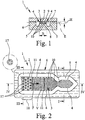
- Fig. 1 shows a schematic section of a first embodiment of a proposed device (1) for receiving and / or diagnosis of a sample liquid (2), in particular blood plasma o.
- the device (1) has a sample liquid (2) by capillary forces receiving channel (3 ) on.
- the channel (3) is open on at least one narrow side or longitudinal side (4), in the representation example on both narrow or long sides (4), as in Fig. 1 indicated. Laterally adjoins the open sides (4) a recess (5), which is preferably groove-like or trench-like in the illustrated embodiment.
- the device (1) has a carrier (6) and an associated cover (7), between which the channel (3) and the recess (5) are formed. If necessary, only the carrier (6) except for the formation of the necessary structures and the cover (7) flat, preferably at least substantially ausbloodungsok formed. However, this can be the other way around.
- the preferably rectangular cross-section recess (5) leads to such, in particular stepped or sudden cross-sectional enlargement, that reduce the capillary forces such that said liquid stop for the sample liquid (2) in the transition from the channel (3) to the recess (5).
- the channel (3) is preferably formed by only two opposite, in particular substantially flat surfaces or flat sides (8) and (9), which in the illustrated embodiment are formed by the carrier (6) or the cover (7) and run parallel, limited or formed. If necessary, therefore, the recess (5) can also be dispensed with altogether and the channel (3) can be formed, for example, by two suitable webs or the like with a suitable distance for producing the desired capillary forces.
- the recess (5) extends in the illustrated embodiment along the open side ( n) (4) of the channel (3), preferably at least along opposite, open longitudinal sides (4). Further, in the illustrated embodiment, the channel (3) is formed laterally open on all sides and the recess (5) is correspondingly formed circumferentially. The channel (3) is thus surrounded on all sides by the recess (5). Preferably, the recess (5) adjoins those narrow sides or longitudinal sides (4) of the channel (3) which are at least substantially parallel to the main filling direction F of the channel (3) with sample liquid (2), as in FIG Fig. 2 indicated, extend.
- the recess (5) preferably extends at least in sections parallel to the main filling direction F.
- the recess (5) with the sample liquid (2) or another, in particular with the sample liquid (2) not mixing liquid, such as oil or the like fills.
- the recess (5) is designed in such a way that its filling speed is at most as great as the filling speed of the channel (3) in order to achieve as uniform a filling as possible with sample liquid (2).
- the filling speeds in each case relate to the filling or advancement of the liquid front V in the main filling direction F.
- the recess (5) can also be rinsed with the other liquid before introducing the sample liquid (2).
- the channel (3) preferably has a substantially rectangular and / or flat cross-section, in particular transversely to the main filling direction F, on.
- height H of the channel (3) - ie the distance of the channel (3) limiting, preferably parallel surfaces (8) and (9) - is a maximum of 2000 microns, preferably at most 500 microns, especially about 50 to 200 microns.
- the recess (5) preferably leads to a gradual or sudden increase in the height H and thereby to form the desired liquid stop.
- the height H of the recess (5) is at least twice as large as the height H of the channel (3).
- the width B of the channel (3) is preferably about 100 to 5000 microns, more preferably about 200 to 4000 microns.
- the height H of the channel (3) is substantially smaller, in particular at least by a factor of 5 or 10, than the width B of the channel (3).
- the receiving volume of the channel (3) is preferably less than 1 ml, in particular less than 100 ⁇ l, more preferably not more than 10 ⁇ l.
- the device (1) thus forms a microfluidic system.
- the channel (3) and thus its Haupthellraum F and main extension plane E extend in the position of use preferably at least substantially horizontally.
- the recording or filling of the channel (3) with sample liquid (2) is preferably at least primarily determined or effected only by capillary forces.
- the main filling direction F can be horizontal or inclined, while the main extension plane E extends vertically, for example, so that the channel (3) is oriented upright.
- the channel (3) preferably forms at least one reservoir for the sample fluid (2), in particular for diagnostics. Possibly.
- the channel (3) may contain a chemical, not shown, in particular a dry chemical or the like.
- examinations of the sample liquid (2) can be made in any other way.
- the channel (3) has at least one guide element for influencing, in particular equalizing, the filling with the sample liquid (2).
- the channel (3) preferably has regularly distributed elevations (10) as guide elements.
- the elevations (10) are the rows offset in the main filling direction F.
- the sample liquid (2) fills the channel (3) in rows - ie row by row - and thereby progresses with a substantially straight-line liquid front V in the main filling direction F.
- the area density, the spacing and / or the size of the elevations (10) may vary, in particular as a function of the respective distance to an in Fig. 1 and Fig. 2 not shown inlet for the sample liquid (2) in the channel (3).
- the elevations (10) are preferably web-like, hump-shaped or column-shaped, in particular with a round or polygonal base surface. Instead, however, depressions may also be provided.
- the channel (3) may comprise at least one trench (11) or a web as a guide element which extends transversely or longitudinally to the main filling direction F of the channel (3).
- the preferably provided groove-like, in cross section in particular rectangular or semicircular trench (11) has a substantially smaller depth than the recess (5) and therefore forms only a temporary liquid stop to even out the liquid front V.
- the sample liquid (2 ) fills only after filling the channel (3) over its entire cross-section of the trench (11) and then the subsequent channel region.
- a highly uniform filling of the channel (3) by capillary forces with at least substantially rectilinear or perpendicular to the main filling direction F extending liquid front V can be achieved by the combination of side wallless guidance of the sample liquid (2) and the guide elements.
- Fig. 3 shows a further schematic section of the device (1) with the cover (7) along line III-III according to Fig. 2 ,
- the device (1) has at least one vent (12) associated with the channel (3) which is not connected directly to the channel (3) but to the recess (5).
- the device (1) has a feed device (13) for receiving and supplying sample liquid (2) to the channel (3).
- the feed device (13) has an opening, in particular opening (14), in the cover (7), preferably for receiving blood o.
- a separator (15) such as a filter, a membrane o .
- the separating device (15) is used in the representation example in a recess (16) open towards the carrier (6) in the cover (7) and covers the opening (14).
- the separator (15) is - in the illustrated embodiment with a flat side - in direct contact with the channel (3), in particular the separator (15) is preferably on columnar structures (17) o. The like. In the channel (3) in a feed ( 18) of the channel (3).
- the structures (17) are preferably provided with wedge-like recesses o. The like., To the blood plasma or the sample liquid (2) by Kapillar founded to the separator (15) opposite channel surface - here to the bottom surface formed by the carrier (8) (8 ) of the channel (3) - and thus to effect a complete filling between the bottom surface (8) and cover (7) and the supply region (18) with sample liquid (2).
- the structures (17) form a filling device for (fully) filling the channel (3) between the cover (7) and the bottom surface (8) with sample liquid (2).
- this filling device may also be formed in any other way, as explained later with reference to the fifth embodiment.
- the sample liquid (2) - in the illustrated example after overcoming the first trench (11) - sucked by capillary forces further into the channel (3), as through the Main filling direction F in Fig. 2 indicated.
- Fig. 4 shows in a schematic longitudinal section of the preferred construction of the proposed device (1) according to the first embodiment, wherein a supply of blood (19) are indicated for illustrative purposes.
- the separating device (15) can, if necessary, contain a chemical, in particular a dry chemical, in particular in order to enable or assist the separation of blood plasma as sample liquid (2) from the blood (19) which is desired in the illustrated embodiment and / or, if necessary, to enable lysis of cells ,
- the separation or forwarding takes place in particular exclusively by capillary forces.
- a single channel (3) for receiving or discharging the sample liquid (2) adjoins the feed device (13).
- the channel (3) in the sense of a single capillary to understand.
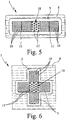
- FIGS. 7 and 8 show a fourth embodiment of the proposed device (1), namely Fig. 7 a top view of the carrier (6) without cover (7) and Fig. 8 a sectional view taken along line VIII-VIII of Fig. 7 with existing cover (7).
- the channel (3) forms here a collecting chamber (20) for the sample liquid (2).
- the collection chamber (20) is in turn substantially flat and has, if necessary, the indicated elevations (10) and / or other guide elements o. The like.
- the device (1) according to the fourth embodiment has a device (21), in particular a light guide or the like, for coupling light into the sample liquid (2), in particular for fluorescence measurements.
- the light strikes the free surface of the sample liquid (2) in the region of an open side (4) of the channel (3) and enters the sample liquid (2) due to a correspondingly steep direction of impact, preferably substantially perpendicular to the liquid surface, as indicated by arrow (22) indicated.
- the interface gas (air) / sample liquid (2) is used for the entrance of light so the interface gas (air) / sample liquid (2) is used.
- the incoming light beam (22) is preferably repeatedly reflected by total reflection at the interface sample liquid (2) / gas (air). This is achieved in that the angle betweenexcellentnlot and incident light beam is greater than the critical angle of total reflection.
- the bottom surface of the collection chamber (20) bounded and defined by the circumferential recess (5) is appropriately selected to achieve the desired beam guidance and total reflection, in the illustrative example by an appropriate polygonal configuration.
- the incident light (22) is used for fluorescence determination or fluorescence spectroscopy.
- the sample liquid (2) in particular marker molecules contained therein o. Like., Which are present for example as a chemical in channel (3) and are dissolved by sample liquid, are excited by a certain wavelength.
- the light beam plane is arranged above such or spaced apart from such structures. Furthermore, the light beam plane extends at least substantially parallel to the main extension plane or in the main extension plane E of the channel (3) or the collection chamber (20). The intended light irradiation and light guidance permit a substantially complete excitation of the sample liquid (2) or of marker molecules contained therein or the like as well as the simultaneous use of microstructures such as the elevations (10) or other guiding elements.
- Fig. 9 shows a schematic longitudinal section of a fifth embodiment of the proposed device (1).
- the filling device for filling the channel (3) between the two flat sides (8) and (9) in particular for discharging the blood plasma or the sample liquid (2) from the separating device (15) or from the top surface (9) to the opposite bottom surface (8) to form a spatial meniscus between the two faces (8) and (9), alternatively or in addition to the structures (17), a ramp (25) , which reduces the channel height H accordingly or possibly even to zero.
- the separating device (15) can be in direct contact with or rest on the ramp (25).
- the said filling device can also be called or understood as a device for lid and floor wetting.
- the schematic sectional view according to Fig. 10 shows a sixth embodiment of the proposed device (1).
- the recess (5) adjoining the channel (3) laterally can be filled by the sample liquid (2) and in such a way - in particular due to a corresponding rounding of its side wall (26) and / or through the formation of corresponding guide elements, such as elevations (10). or the like - formed such that the filling speed of the recess (5) in Haupt Stahl Ferncardi F - in the illustration according to Fig.
- the device according to the proposal (1) is suitable for a wide variety of tests, examinations or the like. In particular, it permits immunological or biochemical tests, for example of blood (19), blood plasma or the like.
- the channel (3) can form a plurality of examination areas or collecting areas (20), which can be filled successively with the sample liquid (2).
- a second examination or collection area (20) may adjoin a first examination or collection area (20), the second area preferably having a considerably higher capillarity, for example by an inserted nonwoven or the like.
- the sample liquid (2) can be subsequently sucked or guided into the second region after filling of the first region and, in particular, after dissolution of a dry chemical present there as required, wherein the dry chemical is washed out of the first region and thus, for example, a further examination in the first and / or second region is made possible.
- a first chemical in particular a dry chemical
- at least one second chemical in particular a dry chemical, preferably in the channel (3) or collecting area (20)
- the first chemical is designed such that it prevents or delays a coagulation of the blood (19).
- EDTA Ethylene Diamine Tetraacetic Acid (ethylene diamine tetraacetic acid)
- EDTA Ethylene Diamine Tetraacetic Acid (ethylene diamine tetraacetic acid)
- the second chemical serves to study or determine one or more parameters in the blood plasma, such as glucose, ketones or lactate.
- the first chemical is designed to lyse cells, such as blood cells, and liberate the calcium or the like.
- lysine buffer is used.
- the second chemical preferably a mixed chemical mixture, an investigation or determination of the parameter, in particular the calcium content.
- a component of the mixture preferably the chelating agent 8-hydroxyquinoline, is used to remove the reaction interfering magnesium ions from the reaction.
- Another complexing agent preferably o-cresolphthalein, forms a colored complex with calcium under alkaline conditions.
- the extinction of the color complex is proportional to the calcium concentration at a wavelength of 570 nm. It is determined directly in the channel (3) or collection area (20) or, if necessary, after removal.
- the extinction can also be used at other wavelengths and / or for the determination of other complexes, parameters or the like. The same applies to other, preferably optical determination methods, such as fluorescence measurements o.
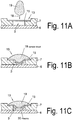
- the distance between the membrane surface and the channel bottom is the same as the channel height Fig. 11A represents.
- the separation element for blood separation can represent a fluidic barrier to the unimpeded flow of the plasma into the channel.
- a membrane or a filter element is used as the separating element, wherein the membrane or the filter element consists of an intertwined fiber network or of a porous material.
- the materials used are non-woven or compressed synthetic fibers or even porous ceramics as well as metal nets.
- the filter material has thin, branched channels with high capillary force through the mesh structure, thereby maintaining fluidic components in the filter or membrane.
- the membrane has a pore size of 0.01 microns to 1.2 microns, especially 0.2 to 0.6 microns.
- the membrane density is 50 microns to 500 microns, preferably 120 microns to 180 microns.
- the porosity that is, the volume fraction of the membrane not carried out with material, is 40-90%, preferably 70 to 80%.
- the pore material may be various materials such as nylon, in particular isotropically foamed nylon 60, with a pore volume greater than 70%, and a pore size of 0.45 micrometers, or preferably hydrophilic polyvinyl difluoride with a pore size of 0.6 micrometers.
- a drop of blood is then introduced into the inlet area in the feed device (18), a hemispherical drop of blood is applied to the surface of the membrane (15) as in FIG 11B can be observed.
- the blood plasma flows through the channels of the membrane (15), retaining the larger blood particles, and forms a plasma film or drop of plasma adhering to the membrane by the hydraulic pressure at the bottom.
- the small amounts of blood or plasma or, in particular, in the case of large dead volumes to be filled between the membrane and the channel bottom the fluidic connection between the plasma and the channel can be omitted.
- a plasma current flows in particular on the channel walls to to the channel bottom and fills the channel (3) or the collecting area (20) slowly.
- the start of the filling process is thereby delayed, which unintentionally causes long flow times, which have a negative effect on the function of a connected to the fluidic channel structure diagnostic or analytical device.
- the dead volume in the filling region between the separating element and the channel thus acts as an impedance or a resistance to the flow rate of the plasma.
- Another object solution of the present invention is to set this impedance targeted, in particular to reduce to a minimum.
- the flow resistance by an embodiment of the separating element (15) according to Fig. 11B be minimized.
- the separating element (15) is convexly shaped in the direction of the channel bottom, so that it preferably rests in a central region on the channel bottom or, alternatively, the apex of the convex shape reaches close to the channel bottom.
- the distance of the separating element, from the bottom of the filling device, in particular from the channel bottom is preferably 1 micron to 100 microns, especially 10 microns to 25 microns.
- the diameter of the membrane (15) used is 2 to 10 millimeters, in particular 250 to 350 micrometers.
- the value W is preferably 100 microns to 300 microns.
- the height value of the curvature should advantageously correspond approximately to the height of a chamber located in the inlet region or under the leading membrane (15).
- the height W of the curvature can also be adapted to the trench depth in the range of 50 to 200 microns vary.
- an element (17) is used with vertical notches on the channel bottom, as in the AP 101 3341 B1 is disclosed.
- the notch geometry initiates and supports a vertical flow from the filling area through the separating element to the channel bottom.
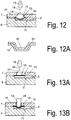
- Fig. 12 shows such elements on the channel bottom, wherein a plurality of elements are arranged to each other at the bottom of the channel, that due to the Kapillarwindung of the interstices, a horizontal volume flow of the fluid or plasma in a collection chamber (20) takes place in the channel direction.
- the convex curvature of the membrane is achieved by compressing the membrane as it is fastened in the direction of its center, causing it to bend towards the center. This can be achieved by making the diameter of the membrane larger than the diameter of the space in which the membrane attached, in particular glued.
- a corresponding holding tool (not shown), which has a convex surface shape, the membrane is inserted into the mounting area and glued. Due to the convex shaping of the tool, the shaping of the membrane deflection takes place.
- thermal methods such as welding, in particular ultrasonic welding, for fastening the membrane, wherein the membrane is advantageously also pressed in here with a preformed holding tool between two plastic elements of the device.
- the convex deflection of the separating element can also be carried out in advance by stamping the mold into the separating element.
- metallic filter elements for example, it is conceivable to press or bend them into a curved, in particular convex, shape.
- Fliesmaterialien would be a stamping process in a correspondingly shaped tool under pressure and / or temperature and / or additionally introduced chemical fixatives or adhesives conceivable.
- the separating element is constructed in two or more parts, in particular two layers, wherein a flexible membrane is arranged on a fixed holding element, in particular a membrane holder (31), such as Fig. 12A shows.
- a membrane holder 31
- the membrane is bonded in the outer region of the funnel-shaped holding element, but it can also be held by clamping elements.
- the funnel-shaped membrane holder or mold insert (29) has a passage opening or bore (32) in a central region, so that when the funnel is filled with blood, it can enter the membrane through the opening (32).
- a separating device has a membrane (15).
- the drop lies on the in Fig. 13A flat membrane (15).
- a plunger (28) inserted into the opening (14), wherein the plunger deformed the membrane surface in the direction of the channel interior, so that adjusts a convex membrane shape.
- the punch (28) is also preferably arched at its end contacting the membrane.
- the introduction of the plunger (28) can be done either manually by an operator or by an automated operating device with actuator drive means.
- the plunger (28) is mounted on an actuator, wherein the actuator moves the plunger so that it pushes down the membrane to the channel bottom.
- the actuator can be made by piezoelectric actuators or a stepper motor or other suitable mechanical or electrical actuators.
- the lowering of the plunger (28) takes place in dependence on the analysis step to be carried out.
- sensors can be attached to the device which detect the supply of a drop of blood (19) and actuate the plunger or punch (28) via a control device, in particular a microprocessor, which receives and processes the sensor signals.
- the channel (3) is formed by a recess (5) in the carrier (6) and a congruent recess in the cover (7).
- the cover (7) has an opening in the end region of the channel (3). This opening (14) is closed off to the top of the cover (7) by a pressure element (33).
- the cover element (33) comprises a punch (28) and an opening (14) through which a drop of blood (19) can be supplied to the feed region (18).
- a separating element (15) in particular a filter membrane is arranged and fixed.
- the attachment can be made for example by gluing or welding to the cover (7).
- the attachment of the membrane to the cover (7) is performed.
- the membrane-providing cover (7) and the carrier (6) are connected together.
- the cover element (33) is fastened to the cover (7), whereby the plunger (28) convexly deforms the membrane so that the dead volume in the feed device (13) is reduced and the apex of the convex membrane ( 27) reaches the vicinity of the channel bottom.
- This will be a Device (1) achieved in which a significantly reduced fluid resistance between the membrane (27) and the channel (3) is present.
- the punch (28) is inserted into a bore in the carrier (6) in the feed area.
- the stamp shank has a first section adjoining the stamp head, which in its length corresponds to the thickness of the support (6) in the region of the bore and seals the bore by inserting the stamp.
- a second section of the stamp shank is provided with notches or a profiling or has through openings in the longitudinal direction of the shaft.
- This second section of the stamp shank extends from the bottom of the feed area (18), in particular the bottom of the channel (3) or the bottom of a collection chamber (20) to the separating element (15) and contacts this, so that through the profiled stamp shank a vertical fluid connection is built up between the floor and a membrane (15).
- the stamp shaft can be provided with elevations or guide elements (10) on its preferably cylindrical lateral surface, which support a Kapillarhne the separated plasma.
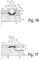
- Fig. 16 shows a device in which the lid member (33) is provided with a central bore (32) through which a drop of blood (19) is introduced into the feed area (18).
- the cover element (33) is fastened to the cover (7), for example welded by means of ultrasound.
- Pressure element (33), cover (7) and carrier (6) are preferably made of plastic material.
- the membrane (27) is clamped between the cover (7) and the carrier (6), in particular welded.
- the pressure element (33) designed as a mold insert (29), wherein the mold insert (29) in the direction of the channel (3) is configured in three dimensions, the membrane is convexly bent and in fluidic contact with the bottom of the channel (3), in particular comes to the guide elements (10) at the bottom of the channel.
- the separating element (15) is first connected to the cover (7) and closes the
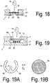
- the carrier element (6) which has a recess in the form of a channel (3), is constructively designed in the region of the opening of the cover (7), ie in the region of the membrane (27) just attached to the cover (7) in a region of the carrier (6) arranged opposite the central region of the opening, the carrier surface is formed beyond the connecting plane between carrier (6) and cover (7).
- This can be achieved, for example, by the fact that as in Fig. 17 provided the surface of the carrier (6) in this area convex convex, this presses against the membrane (27) and according to the shape of the carrier (6) deflects accordingly.
- the support surface is also provided in this area with guide elements (10), which cause a horizontal fluid flow of the plasma.
- the device (1) is constructed in three layers.
- the carrier (6) is connected to the cover via an intermediate element (34), in this case the channel element (34) forming the channel.
- the intermediate element (34) is adhesively bonded, for example, to the carrier (6) and to the cover (7).
- the intermediate element (34) is preferably a two-sided adhesive film.
- the channel structures, in particular the channel (3) are introduced as recesses (16) in the intermediate element, for example by punching out of the finished form or as recesses in the molding or casting process.
- the cover (7) and the carrier (6) are designed as flat elements without recesses (5) for the fluid-conducting structures, which requires the use of precise, cost-intensive microforming tools significantly reduced and makes the production easier.
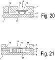
- Fig. 18 is for the preparation of a fluidic contact and to reduce the flow resistance in the inlet region of the channel provided to form the carrier element (6) in the direction of the membrane (27), in particular at least one pin (37) in the carrier element (6) to bring in from the connection plane between the channel element (34) and the support element (6) protrudes in the direction of the membrane and makes a fluidic contact with the membrane.
- the pin (37), for example, in the production of the carrier (6) can be introduced directly by molding or downstream by mechanical and / or thermal impressions in the carrier element.
- the channel (3) as a recess (5) in the carriers (6) is formed.
- the separating device (15) in this case a filter element (15), is arranged in a recess (16) of the cover (7) and together with the insert element or insert (35) forms the tension guiding device (13). If a drop (19) of blood is now supplied to the feed region (18), the blood is absorbed by the filter (15) and filtered, the plasma exiting in the channel direction being taken up by the insert (35) arranged on the channel side of the filter (15) becomes.
- the insert (35) is geometrically designed such that its height corresponds approximately to the height of the space between the channel bottom and the underside of the filter (15) and the insert (35) both the channel bottom or chamber bottom in the inlet region as well as the bottom of the filter contacted.
- the insert (35) is an insert element (35), which means that the insert (35) when mounting the carrier (6) with the cover (7) its attachment learns by the fact that he from the contact pressure between the filter and the carrier (6) is held.
- the insert can be made for example as an O-ring made of an elastic plastic or a rubber.
- this consists of a further filter material, this may be a porous ceramic, a sponge made of fiber material, a metallic mesh or mesh element or any other suitable element of channel-carrying structures.
- the insert (35) is designed as a horseshoe-shaped insert element (35).
- the insert element can be made of non-porous Plastic material, but it is also conceivable to produce the insert element of one of the above channel-carrying materials.
- the insertion element in the edge region at least one notch (36), in particular a plurality of notches (36), which support a vertical discharge of the plasma into the plasma chamber (20) or the channel (3).
- the cross section of the inserts is wedge-shaped, as the section AA in Fig. 19A shows, wherein the tip of the wedge contacts the membrane surface and thereby establishes the fluid contact.
- the air present in the volume of the feed region can be enclosed in the filling region by means of a drop of blood during the filling.
- a cover (7) and an intermediate element (34) In order to ensure that in a structure with a carrier (6), a cover (7) and an intermediate element (34), a tight seal of the filter (15) is achieved, this is provided in its mounting region with a pressure (38), which compresses the filter material in the area of the pressure (38).
- a pressure (38) which compresses the filter material in the area of the pressure (38).
- Fig. 21 is in a support member (6) a recess (5) formed, which forms the channel (3).
- the intermediate element is a film-like plastic part provided with an adhesive on both sides, the adhesive making contact by gluing both to the cover (7) and to the carrier (6) and connecting them together.
- an insert (35) in the form of an insert (35) is arranged in the region of the feed device.
- the separator or the filter (15) is glued or welded into the cover (7), wherein the welding takes place for example by means of ultrasound or by means of thermal welding.
- the feed area is shown from above.
- the intermediate element (34) can be seen, which is, for example, a channel element with punched holes which form a sample collection chamber (20) in the feed region and a channel (3).
- the guide elements (10) can be seen in the region of the sample chamber (20).
- the welding line (fixing line) (39) is schematically illustrated, which in the upper cover (7) prevents the filter or the filter membrane (15) with the cover.
- the intermediate element is in particular a film which is provided on both sides with an adhesive.
- the separated plasma flows into the collection chamber (20) and is derived by the guide elements supportive in the channel (3).
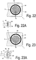
- the inlet region of the channel (3) represents a clear and abrupt reduction of the flow cross-section.
- Fig. 22A shows, it can come to the influx of air into the channel (3), whereby flowing air bubbles can get into the channel, which can significantly increase the flow resistance or bring the flow flow completely to a standstill.
- the transverse inflow of air (40) since the filter material by the compression at this point during welding leaves a cavity from which air can flow.
- Fig. 23 provided to continuously reduce the flow area from the collection chamber to the channel along a transition region. This can be done, for example step by step, by like FIG. 22 can be seen, first a reduction in the cross-sectional area is carried out so far that the reduced cross section (41) is about 2 to 5 times the cross section of the channel (3).
- the cross-sectional step (41) is arranged such that the circumferential attachment line (39) brakes the outlet region from the collection chamber (20) in the region of the cross-sectional step and forms no intersection with the channel (3), whereby a direct inflow of air (40) in the channel (3) is avoided.
- These vanes help to support wetting by vertical fluid flow.
- a horizontal fluid flow is also supported by the capillary-acting intermediate spaces between the guide elements (10).
- All these embodiments have in common that the guide elements are not an essential functional component.
- a guide element (10) and the respective existing capillary gap between a filter and or a membrane (15) and the bottom of a channel (3) or a feed device (18) as influenced by the curvature of the soil to the membrane wedge-shaped capillary gaps with low height and high capillarity can be set in the contact surfaces or the nutritional surfaces.
Description
Die vorliegende Erfindung betrifft eine Vorrichtung zur Aufnahme von Blut und Abtrennung von Blutbestandteilen, wie Blutplasma, als Probenflüssigkeit.The present invention relates to a device for receiving blood and separating blood components, such as blood plasma, as a sample liquid.
Die vorliegende Erfindung befasst sich mit mikrofluidischen Systemen bzw. Vorrichtungen. Die nachfolgenden Ausführungen beziehen sich auf Vorrichtungen, bei denen Kapillarkräfte wirken und insbesondere für die Funktion entscheidend sind.The present invention is concerned with microfluidic systems. The following statements relate to devices in which act capillary forces and are particularly crucial for the function.
Aus der
Aus der
Der vorliegenden Erfindung liegt die Aufgabe zugrunde, eine verbesserte Vorrichtung und ein verbessertes Verfahren zur Aufnahme von Blut und Abtrennung von Blutbestandteilen, wie Blutplasma, als Probenflüssigkeit bereitzustellen, wobei ein optimiertes Füllen des Kanals mit Probenflüssigkeit ermöglicht wird und wobei ein Kapillarkontakt zwischen dem Seperationselement und dem Kanal hergestellt wird und vorzugsweise die diagnostischen bzw. Untersuchungsmöglichkeiten verbessert werden.The present invention has for its object to provide an improved apparatus and an improved method for receiving blood and separation of blood components, such as blood plasma, as sample liquid, wherein an optimized filling of the channel with sample liquid is made possible and wherein a capillary contact between the separation element and the Channel is made and preferably the diagnostic or investigation options can be improved.
Eine grundlegende Idee der vorliegenden Erfindung liegt darin, eine Einrichtung zum Herstellen eines fluidischen Kapillarkontaktes zwischen Seperationselementen, insbesondere Membranen und einem Leitungskanal vorzusehen. Dies gestattet ein optimales, schnelles und gleichmäßiges Füllen des Kanals und verhindert unerwünschte Lufteinschlüsse.
Vorzugsweise wird die Probenflüssigkeit durch Kapillarkräfte in einem Kanal aufgenommen, der zumindest an einer Schmalseite oder Längsseite offen ausgebildet ist, so dass ein seitlicher Flüssigkeitsstopp für die Probenflüssigkeit im Kanal gebildet wird und die Probenflüssigkeit seitenwandfrei im Kanal führbar ist. Insbesondere schließt sich hierbei eine Ausnehmung seitlich an die offene Seite des Kanals an.A basic idea of the present invention is to provide a device for producing a fluidic capillary contact between separation elements, in particular membranes and a duct. This allows for optimal, fast and even filling of the channel and prevents unwanted air pockets.
Preferably, the sample liquid is taken up by capillary forces in a channel, is formed open at least on one narrow side or longitudinal side, so that a lateral liquid stop for the sample liquid is formed in the channel and the sample liquid can be guided sidewall free in the channel. In particular, in this case, a recess connects laterally to the open side of the channel.
So kann auf einfache Weise ein Vorschiessen der Probenflüssigkeit - also schnelleres Füllen des Kanals - im Bereich einer ansonsten vorhandenen Seitenwand verhindert werden. Dies ermöglicht eine Vergleichmäßigung der Füllgeschwindigkeit über den gesamten Kanalquerschnitt, so dass eine zumindest im Wesentlichen gleichmäßige bzw. gradlinige Flüssigkeitsfront beim Füllen des Kanals erreichbar ist.
Die seitlich offene Ausbildung des Kanals gestattet eine verbesserte, insbesondere optimale Entlüftung beim Füllen des Kanals mit Probenflüssigkeit.
Außerdem gestattet die seitenwandfrei gehaltene bzw. geführte Oberfläche der Probenflüssigkeit eine unmittelbare Untersuchung der Probenflüssigkeit, insbesondere durch Einkopplung von Licht, ohne eine ansonsten vorhandene Seitenwand o. dgl.
Vorzugsweise ist die Ausnehmung grabenartig ausgebildet und umgibt den insbesondere allseitig seitlich offenen Kanal vollständig. So können insbesondere bei sehr feinen Strukturen die ansonsten beim Übergang von Flachseiten zu Schmalseiten auftretenden Innenkanten mit besonders hohen Kapillarkräften insgesamt vermieden werden. Jedoch gilt entsprechendes auch bei einer nur abschnittsweise seitlich offenen Ausbildung des Kanals. Alternativ kann die sich seitlich an den Kanal anschließende Ausnehmung oder Seitenwandung auch mit Probenflüssigkeit oder einer sonstigen Flüssigkeit füllbar sein. Hierbei ist die Ausnehmung oder Seitenwandung dann derart - insbesondere hinsichtlich ihrer Größe, Krümmungen oder ihrem Benetzungsverhalten - oder durch Leitelemente gestaltet, dass die Füllgeschwindigkeit des Kanals mit der Probenflüssigkeit größer oder gleich der Füllgeschwindigkeit der Ausnehmung oder entlang der Seitenwandung jeweils in Füllrichtung - insbesondere Längsrichtung - des Kanals ist. So kann ebenfalls ein seitliches Vorschiessen der Flüssigkeitsfront beim Füllen mit Probenflüssigkeit vermieden werden.Thus, a pre-shooting of the sample liquid - ie faster filling of the channel - in the range of an otherwise existing side wall can be prevented in a simple manner. This makes it possible to even out the filling speed over the entire channel cross-section, so that an at least substantially uniform or straight-lined liquid front can be reached when filling the channel.
The laterally open design of the channel allows improved, in particular optimal ventilation when filling the channel with sample liquid.
In addition, the side wall free held or guided surface of the sample liquid allows a direct examination of the sample liquid, in particular by coupling light, without an otherwise existing side wall o. The like.
Preferably, the recess is trench-like and surrounds the channel, in particular laterally open, completely. Thus, especially with very fine structures, the inner edges which otherwise occur during the transition from flat sides to narrow sides with particularly high capillary forces can be avoided altogether. However, the same applies also in the case of only a sectionally laterally open design of the channel. Alternatively, the recess or side wall adjoining the channel laterally can also be filled with sample liquid or another liquid. Here, the recess or side wall is then such - in particular with regard to their size, curvature or wetting behavior - or designed by guide elements that the filling speed of the channel with the sample liquid is greater than or equal to the filling speed of the recess or along the side wall in the filling direction - in particular longitudinal direction - the channel is. Thus, a lateral Vorschiessen the liquid front when filling with sample liquid can also be avoided.
Ein weiteres vorschlagsgemäßes Verfahren zur Bestimmung eines Parameters im Blutplasma bzw. eines Blutbestandteils zeichnet sich dadurch aus, dass in einem mikrofluidischen System unmittelbar nach dem Zurückhalten bzw. Abtrennen von Blutzellen direkt eine Bestimmung eines Bestandteils bzw. Parameters des Blutplasmas mittels einer Chemikalie oder mehreren Chemikalien erfolgt. Dies gestattet bei einfachem und kompaktem Aufbau eine schnelle und preisgünstige Analyse bzw. Bestimmung des Parameters.Another proposed method for determining a parameter in the blood plasma or a blood component is characterized in that in a microfluidic system directly after the retention or separation of blood cells directly a determination of a component or parameter of the blood plasma by means of a chemical or more chemicals , This allows a simple and compact design a quick and inexpensive analysis or determination of the parameter.
Weitere Vorteile, Merkmale, Eigenschaften und Aspekte der vorliegenden Erfindung ergeben sich aus den Ansprüchen und der folgenden Beschreibung bevorzugter Ausführungsformen anhand der Zeichnung. Es zeigt:
-
Fig. 1 einen schematischen Schnitt einer vorschlagsgemäßen Vorrichtung gemäß einer ersten Ausführungsform; -
Fig. 2 eine schematische Draufsicht eines Trägers der gefüllten Vorrichtung gemäßFig. 1 ; -
Fig. 3 einen schematischen Schnitt der Vorrichtung entlang Linie III-III gemäßFig. 2 ; -
Fig. 4 einen schematischen Längsschnitt der Vorrichtung entlang Linie IV-IV gemäßFig. 2 ; -
Fig. 5 eine schematische Draufsicht eines Trägers einer vorschlagsgemäßen Vorrichtung gemäß einer zweiten Ausführungsform; -
Fig. 6 eine schematische Draufsicht eines Trägers einer vorschlagsgemäßen Vorrichtung gemäß einer dritten Ausführungsform; -
Fig. 7 eine Ausschnittsweise schematische Draufsicht eines Trägers einer vorschlagsgemäßen Vorrichtung gemäß einer vierten Ausführungsform; -
Fig. 8 einen Ausschnittsweisen, schematischen Schnitt der Vorrichtung entlang Linie VIII-VIII gemäßFig. 7 ; -
Fig. 9 einen schematischen Längsschnitt einer vorschlagsgemäßen Vorrichtung gemäß einer fünften Ausführungsform; und -
Fig. 10 einen schematischen Schnitt einer vorschlagsgemäßen Vorrichtung gemäß einer sechsten Ausführungsform; -
Fig. 11A , B, C undFig. 12 Ausführungsform mit gewölbten Membrananordnung; -
Fig. 13 ,Fig. 14 ,Fig. 15 undFig. 16 Ausführungen mit einer durch einen Stempel gewölbten Membran; -
Fig. 17 undFig. 18 Ausführungsformen mit gewölbten Trägerboden; -
Fig. 19 und Fig. 19A , B, C Ausführungen mit einem Einlegeeinsatz; -
Fig. 20 eine Ausführung mit einer Entlüftung; -
Fig. 21 eine Ausführung mit verschweißter Membran und -
Fig. 22, Fig. 22A, Fig. 23 und Fig. 23A eine Aufweitung des Kanaleinlassquerschnittes.
-
Fig. 1 a schematic section of a proposed device according to a first embodiment; -
Fig. 2 a schematic plan view of a carrier of the filled device according toFig. 1 ; -
Fig. 3 a schematic section of the device along line III-III according toFig. 2 ; -
Fig. 4 a schematic longitudinal section of the device along line IV-IV according toFig. 2 ; -
Fig. 5 a schematic plan view of a support of a proposed device according to a second embodiment; -
Fig. 6 a schematic plan view of a carrier of a proposed device according to a third embodiment; -
Fig. 7 a fragmentary schematic plan view of a carrier of a proposed device according to a fourth embodiment; -
Fig. 8 a fragmentary, schematic section of the device along line VIII-VIII according toFig. 7 ; -
Fig. 9 a schematic longitudinal section of a proposed device according to a fifth embodiment; and -
Fig. 10 a schematic section of a proposed device according to a sixth embodiment; -
Fig. 11A , B, C andFig. 12 Embodiment with a curved membrane arrangement; -
Fig. 13 .Fig. 14 .Fig. 15 andFig. 16 Versions with a membrane curved by a stamp; -
Fig. 17 andFig. 18 Embodiments with a curved support base; -
Figs. 19 and 19A , B, C versions with a insert insert; -
Fig. 20 a version with a vent; -
Fig. 21 a version with welded membrane and -
Figs. 22, 22A, 23 and 23A an expansion of the channel inlet cross-section.
In den Figuren werden für gleiche oder ähnliche Teile dieselben Bezugszeichen verwendet, wobei entsprechende oder vergleichbare Eigenschaften und Vorteile erreicht werden, auch wenn eine wiederholte Beschreibung weggelassen ist.
Seitlich schließt sich an die offenen Seiten (4) eine Ausnehmung (5) an, die beim Darstellungsbeispiel vorzugsweise nut- bzw. grabenartig ausgebildet ist.
So wird ein seitlicher Flüssigkeitsstopp für die Probenflüssigkeit (2) - also ein durch Kapillarkräfte nicht überwindbares Strömungshindernis - im Kanal (3) gebildet und ist die Probenflüssigkeit (2) seitenwandfrei entlang der offenen Seiten (4) im Kanal (3) führbar. Beim Darstellungsbeispiel weist die Vorrichtung (1) einen Träger (6) und eine zugeordnete Abdeckung (7) auf, zwischen denen der Kanal (3) und die Ausnehmung (5) gebildet sind. Bedarfsweise ist lediglich der Träger (6) zur Bildung der erforderlichen Strukturen ausgenommen und die Abdeckung (7) eben, vorzugsweise zumindest im Wesentlichen ausnehmungsfrei, ausgebildet. Jedoch kann dies auch umgekehrt sein. Bedarfsweise können aber auch sowohl der Träger (6) als auch die Abdeckung (7) ausgenommen und/oder mit Vorsprüngen zur Bildung der gewünschten Strukturen und ggf. zur Aufnahme von nicht dargestellten Chemikalien, Reagenzien, Untersuchungseinrichtungen o. dgl. ausgebildet sein.
Die Ausnehmung (5) schließt sich vorzugsweise scharfkantig an den Kanal (3) an, wie in
Die im Querschnitt vorzugsweise rechteckige Ausnehmung (5) führt zu einer derartigen, insbesondere stufigen bzw. plötzlichen Querschnittsvergrößerung, dass sich die Kapillarkräfte derartig verringern, dass der genannte Flüssigkeitsstopp für die Probenflüssigkeit (2) im Übergang vom Kanal (3) zur Ausnehmung (5) hin gebildet wird, wie in
Der Kanal (3) wird vorzugsweise von nur zwei gegenüberliegenden, insbesondere im wesentlichen ebenen Flächen bzw. Flachseiten (8) und (9), die beim Darstellungsbeispiel durch den Träger (6) bzw. die Abdeckung (7) gebildet sind und parallel verlaufen, begrenzt bzw. gebildet. Bedarfsweise kann daher die Ausnehmung (5) auch ganz entfallen und der Kanal (3) beispielsweise durch zwei geeignete Stege o. dgl. mit geeignetem Abstand zur Erzeugung der gewünschten Kapillarkräfte gebildet sein.
Der Kanal (3) ist also allseitig von der Ausnehmung (5) umgeben.
Vorzugsweise schließt sich die Ausnehmung (5) an diejenigen Schmalseiten bzw. Längsseiten (4) des Kanals (3) an, die sich zumindest im Wesentlichen parallel zur Hauptfüllrichtung F des Kanals (3) mit Probenflüssigkeit (2), wie in
Gemäß einer anderen, später anhand von
Alternativ kann die Ausnehmung (5) vor Einleiten der Probenflüssigkeit (2) auch nur mit der anderen Flüssigkeit gespült werden.
Der Kanal (3) weist vorzugsweise einen im Wesentlichen rechteckigen und/oder flachen Querschnitt, insbesondere quer zur Hauptfüllrichtung F, auf.
Die in
Die Breite B des Kanals (3) beträgt vorzugsweise etwa 100 bis 5000 Mikrometer, insbesondere etwa 200 bis 4000 Mikrometer.
Die Höhe H des Kanals (3) ist wesentlich geringer, insbesondere mindestens um den Faktor 5 oder 10, als die Breite B des Kanals (3).
Das Aufnahmevolumen des Kanals (3) beträgt vorzugsweise weniger als 1 ml, insbesondere weniger als 100 [mu]l, besonders bevorzugt maximal 10 [mu]l.
Die Vorrichtung (1) bildet also ein mikrofluidisches System. Insbesondere dient die Vorrichtung (1) der mikrofluidischen Diagnostik für medizinische oder nicht-medizinische Zwecke bzw. sonstige Untersuchungen.
Der Kanal (3) und damit dessen Hauptfüllrichtung F und Haupterstreckungsebene E verlaufen in Gebrauchslage vorzugsweise zumindest im Wesentlichen horizontal. Je nach Verwendungszweck oder konstruktiver Lösung ist jedoch auch eine andere Ausrichtung möglich, zumal die Aufnahme bzw. das Füllen des Kanals (3) mit Probenflüssigkeit (2) vorzugsweise zumindest primär nur durch Kapillarkräfte bestimmt bzw. bewirkt wird.
So kann die Hauptfüllrichtung F beispielsweise horizontal oder geneigt verlaufen, während die Haupterstreckungsebene E beispielsweise vertikal verläuft, so dass der Kanal (3) also hochkant ausgerichtet ist.
Der Kanal (3) bildet vorzugsweise mindestens einen Speicher für die Probenflüssigkeit (2), insbesondere zur Diagnostik. Ggf. kann der Kanal (3) eine nicht dargestellte Chemikalie, insbesondere eine Trockenchemikalie o. dgl., enthalten. Jedoch können Untersuchungen der Probenflüssigkeit (2) auch auf sonstige Weise vorgenommen werden.
Beim Darstellungsbeispiel weist der Kanal (3) mindestens ein Leitelement zur Beeinflussung, insbesondere Vergleichmäßigung, des Füllens mit der Probenflüssigkeit (2) auf.
Gemäß einer Ausbildungsvariante weist der Kanal (3) vorzugsweise regelmäßig verteilte Erhöhungen (10) als Leitelemente auf. Diese sind insbesondere in Reihen quer, vorzugsweise senkrecht, oder längs zur Hauptfüllrichtung F, insbesondere abwechselnd quer versetzt, angeordnet. Die Erhöhungen (10) sind die Reihen in Hauptfüllrichtung F versetzt. So kann erreicht werden, dass die Probenflüssigkeit (2) den Kanal (3) reihenweise - also Reihe für Reihe - füllt und dadurch mit einer im wesentlichen gradlinigen Flüssigkeitsfront V in Hauptfüllrichtung F fortschreitet.
Bedarfsweise kann die Flächendichte, der Abstand und/oder die Größe der Erhöhungen (10) variieren, insbesondere in Abhängigkeit von der jeweiligen Entfernung zu einem in
Die Erhöhungen (10) sind vorzugsweise steg-, höcker- oder säulenartig, insbesondere mit runder oder polygonaler Grundfläche, ausgebildet. Stattdessen können aber auch Vertiefungen vorgesehen sein.
Alternativ oder zusätzlich kann der Kanal (3) mindestens einen Graben (11) oder einen Steg als Leitelement aufweisen, der quer oder längs zur Hauptfüllrichtung F des Kanals (3) verläuft. Der vorzugsweise vorgesehene nutartige, im Querschnitt insbesondere rechteckige oder halbrunde Graben (11) weist eine wesentlich geringere Tiefe als die Ausnehmung (5) auf und bildet daher einen nur temporären Flüssigkeitsstopp zur Vergleichmäßigung der Flüssigkeitsfront V. So kann erreicht werden, dass die Probenflüssigkeit (2) erst nach Füllen des Kanals (3) über seinen gesamten Querschnitt den Graben (11) und anschließend den nachfolgenden Kanalbereich füllt.
Hervorzuheben ist, dass durch die Kombination der seitenwandlosen Führung der Probenflüssigkeit (2) und der Leitelemente ein hochgradig gleichmäßiges Füllen des Kanals (3) durch Kapillarkräfte mit zumindest im wesentlichen gradliniger bzw. senkrecht zur Hauptfüllrichtung F verlaufender Flüssigkeitsfront V erreichbar ist.
Alternativ kann der Kanal (3) und/oder ein davon gebildeter Speicher, Sammelraum,
Sammelbereich o. dgl. auch zumindest im Wesentlichen glatt bzw. eben, also insbesondere ohne Leitelemente, ausgebildet sein.
Die Vorrichtung (1) weist mindestens eine dem Kanal (3) zugeordnete Entlüftung (12) auf, die nicht unmittelbar an den Kanal (3), sondern an die Ausnehmung (5) angeschlossen ist. So ist kein zusätzlicher Flüssigkeitsstopp für die Entlüftung (12), um ein Austreten von Probenflüssigkeit (2) durch die Entlüftung (12) zu verhindern, erforderlich. Die vorzugsweise allseitig seitlich offene Ausbildung des Kanals (3) gestattet ein optimales Entlüften beim Füllen des Kanals (3) mit der Probenflüssigkeit (2), so dass unerwünschte Lufteinschlüsse sicher vermieden werden können.
Die Probenflüssigkeit (2) ist dem Kanal (3) vorzugsweise senkrecht zur Kanalerstreckung E, insbesondere in Gebrauchslage vertikal, zuführbar.
Die Vorrichtung (1) weist eine Zuführeinrichtung (13) zur Aufnahme und Zuführung von Probenflüssigkeit (2) zum Kanal (3) auf. Beim Darstellungsbeispiel weist die Zuführeinrichtung (13) eine Öffnung, insbesondere Durchbrechung (14), in der Abdeckung (7), vorzugsweise zur Aufnahme von Blut o. dgl., sowie eine Trenneinrichtung (15), wie einen Filter, eine Membran o. dgl., zur Abtrennung von Blutplasma als Probenflüssigkeit (2) auf. Die Trenneinrichtung (15) ist beim Darstellungsbeispiel in eine zum Träger (6) hin offene Aussparung (16) in der Abdeckung (7) eingesetzt und deckt die Durchbrechung (14) ab. Vorzugsweise ist die Trenneinrichtung (15) mit der Abdeckung (7) fest verbunden, beispielsweise verschweißt, verklebt oder von dieser kraft- oder formflüssig gehalten.
Die Trenneinrichtung (15) steht - beim Darstellungsbeispiel mit einer Flachseite - unmittelbar mit dem Kanal (3) in Kontakt, insbesondere liegt die Trenneinrichtung (15) auf vorzugsweise säulenartigen Strukturen (17) o. dgl. im Kanal (3) in einem Zuführbereich (18) des Kanals (3) auf. Die Strukturen (17) sind vorzugsweise mit keilartigen Ausnehmungen o. dgl. versehen, um das Blutplasma bzw. die Probenflüssigkeit (2) durch Kapillarkräfte zu der der Trenneinrichtung (15) gegenüberliegenden Kanalfläche - hier zu der vom Träger (6) gebildeten Bodenfläche (8) des Kanals (3) - zu leiten und so eine vollständige Füllung zwischen Bodenfläche (8) und Abdeckung (7) bzw. des Zuführbereichs (18) mit Probenflüssigkeit (2) zu bewirken.
Die Strukturen (17) bilden eine Fülleinrichtung zum (vollständigen) Füllen des Kanals (3) zwischen Abdeckung (7) und Bodenfläche (8) mit Probenflüssigkeit (2).
Diese Fülleinrichtung kann jedoch auch in sonstiger Weise ausgebildet sein, wie später noch anhand der fünften Ausführungsform erläutert.
Anschließend wird die Probenflüssigkeit (2) - beim Darstellungsbeispiel nach Überwindung des ersten Grabens (11) - durch Kapillarkräfte weiter in den Kanal (3) gesaugt, wie durch die Hauptfüllrichtung F in
Laterally adjoins the open sides (4) a recess (5), which is preferably groove-like or trench-like in the illustrated embodiment.
Thus, a lateral liquid stop for the sample liquid (2) - ie an insurmountable by capillary forces flow obstacle - in the channel (3) is formed and the sample liquid (2) side wall free along the open sides (4) in the channel (3) feasible. In the illustrated example, the device (1) has a carrier (6) and an associated cover (7), between which the channel (3) and the recess (5) are formed. If necessary, only the carrier (6) except for the formation of the necessary structures and the cover (7) flat, preferably at least substantially ausnehmungsfrei formed. However, this can be the other way around. If necessary, however, both the support (6) and the cover (7) can be recessed and / or formed with projections for forming the desired structures and, if necessary, for receiving chemicals, reagents, examination devices or the like, not shown.
The recess (5) preferably adjoins the channel (3) in a sharp-edged manner, as in FIG
The preferably rectangular cross-section recess (5) leads to such, in particular stepped or sudden cross-sectional enlargement, that reduce the capillary forces such that said liquid stop for the sample liquid (2) in the transition from the channel (3) to the recess (5). is formed as in
The channel (3) is preferably formed by only two opposite, in particular substantially flat surfaces or flat sides (8) and (9), which in the illustrated embodiment are formed by the carrier (6) or the cover (7) and run parallel, limited or formed. If necessary, therefore, the recess (5) can also be dispensed with altogether and the channel (3) can be formed, for example, by two suitable webs or the like with a suitable distance for producing the desired capillary forces.
The channel (3) is thus surrounded on all sides by the recess (5).
Preferably, the recess (5) adjoins those narrow sides or longitudinal sides (4) of the channel (3) which are at least substantially parallel to the main filling direction F of the channel (3) with sample liquid (2), as in FIG
According to another, later based on
Alternatively, the recess (5) can also be rinsed with the other liquid before introducing the sample liquid (2).
The channel (3) preferably has a substantially rectangular and / or flat cross-section, in particular transversely to the main filling direction F, on.
In the
The width B of the channel (3) is preferably about 100 to 5000 microns, more preferably about 200 to 4000 microns.
The height H of the channel (3) is substantially smaller, in particular at least by a factor of 5 or 10, than the width B of the channel (3).
The receiving volume of the channel (3) is preferably less than 1 ml, in particular less than 100 μl, more preferably not more than 10 μl.
The device (1) thus forms a microfluidic system. In particular, the device (1) of the microfluidic diagnostic for medical or non-medical purposes or other investigations.
The channel (3) and thus its Hauptfüllrichtung F and main extension plane E extend in the position of use preferably at least substantially horizontally. Depending on the intended use or constructive solution, however, is also a different orientation possible, especially as the recording or filling of the channel (3) with sample liquid (2) is preferably at least primarily determined or effected only by capillary forces.
For example, the main filling direction F can be horizontal or inclined, while the main extension plane E extends vertically, for example, so that the channel (3) is oriented upright.
The channel (3) preferably forms at least one reservoir for the sample fluid (2), in particular for diagnostics. Possibly. For example, the channel (3) may contain a chemical, not shown, in particular a dry chemical or the like. However, examinations of the sample liquid (2) can be made in any other way.
In the illustrated example, the channel (3) has at least one guide element for influencing, in particular equalizing, the filling with the sample liquid (2).
According to a variant embodiment, the channel (3) preferably has regularly distributed elevations (10) as guide elements. These are in particular arranged in rows transversely, preferably vertically, or longitudinally to the main filling direction F, in particular alternately transversely offset. The elevations (10) are the rows offset in the main filling direction F. Thus, it can be achieved that the sample liquid (2) fills the channel (3) in rows - ie row by row - and thereby progresses with a substantially straight-line liquid front V in the main filling direction F.
If required, the area density, the spacing and / or the size of the elevations (10) may vary, in particular as a function of the respective distance to an in
The elevations (10) are preferably web-like, hump-shaped or column-shaped, in particular with a round or polygonal base surface. Instead, however, depressions may also be provided.
Alternatively or additionally, the channel (3) may comprise at least one trench (11) or a web as a guide element which extends transversely or longitudinally to the main filling direction F of the channel (3). The preferably provided groove-like, in cross section in particular rectangular or semicircular trench (11) has a substantially smaller depth than the recess (5) and therefore forms only a temporary liquid stop to even out the liquid front V. Thus, it can be achieved that the sample liquid (2 ) fills only after filling the channel (3) over its entire cross-section of the trench (11) and then the subsequent channel region.
It should be emphasized that a highly uniform filling of the channel (3) by capillary forces with at least substantially rectilinear or perpendicular to the main filling direction F extending liquid front V can be achieved by the combination of side wallless guidance of the sample liquid (2) and the guide elements.
Alternatively, the channel (3) and / or a memory formed therefrom, collecting space,
Collection area o. The like. Also at least substantially smooth or flat, so in particular without guide elements, be formed.
The device (1) has at least one vent (12) associated with the channel (3) which is not connected directly to the channel (3) but to the recess (5). Thus, no additional liquid stop is required for the vent (12) to prevent leakage of sample liquid (2) through the vent (12). The preferably on all sides laterally open design of the channel (3) allows an optimal venting when filling the channel (3) with the sample liquid (2), so that unwanted air pockets can be safely avoided.
The sample liquid (2) can preferably be fed vertically to the channel (3) perpendicular to the channel extension E, in particular in the position of use.
The device (1) has a feed device (13) for receiving and supplying sample liquid (2) to the channel (3). In the illustrated embodiment, the feed device (13) has an opening, in particular opening (14), in the cover (7), preferably for receiving blood o. The like., And a separator (15), such as a filter, a membrane o ., For the separation of blood plasma as a sample liquid (2). The separating device (15) is used in the representation example in a recess (16) open towards the carrier (6) in the cover (7) and covers the opening (14). Preferably, the separating device (15) with the cover (7) fixedly connected, for example, welded, glued or held by this force or form liquid.
The separator (15) is - in the illustrated embodiment with a flat side - in direct contact with the channel (3), in particular the separator (15) is preferably on columnar structures (17) o. The like. In the channel (3) in a feed ( 18) of the channel (3). The structures (17) are preferably provided with wedge-like recesses o. The like., To the blood plasma or the sample liquid (2) by Kapillarkräfte to the separator (15) opposite channel surface - here to the bottom surface formed by the carrier (8) (8 ) of the channel (3) - and thus to effect a complete filling between the bottom surface (8) and cover (7) and the supply region (18) with sample liquid (2).
The structures (17) form a filling device for (fully) filling the channel (3) between the cover (7) and the bottom surface (8) with sample liquid (2).
However, this filling device may also be formed in any other way, as explained later with reference to the fifth embodiment.
Subsequently, the sample liquid (2) - in the illustrated example, after overcoming the first trench (11) - sucked by capillary forces further into the channel (3), as through the Main filling direction F in
Die Trenneinrichtung (15) kann bedarfsweise eine Chemikalie, insbesondere eine Trockenchemikalie, enthalten, insbesondere um die beim Darstellungsbeispiel gewünschte Abtrennung von Blutplasma als Probenflüssigkeit (2) vom Blut (19) zu ermöglichen oder zu unterstützen und/oder bedarfsweise eine Lysierung von Zellen zu ermöglichen. Die Abtrennung bzw. Weiterleitung erfolgt insbesondere ausschließlich durch Kapillarkräfte. Vorzugsweise schließt sich an die Zuführeinrichtung (13) nur ein einziger Kanal (3) zur Aufnahme oder Ableitung der Probenflüssigkeit (2) an. Hierbei ist der Kanal (3) im Sinne einer Einzelkapillare zu verstehen. Bedarfsweise kann der Kanal (3) jedoch in unterschiedliche Richtungen oder zu unterschiedlichen Bereichen führen oder sich verzweigen, wie nachfolgend unter Bezugnahme auf die zweite Ausführungsform gemäß
Bei der zweiten Ausführungsform gemäß
Bei der dritten Ausführungsform gemäß
Sowohl bei der zweiten Ausführungsform als auch bei der dritten Ausführungsform ist vorzugsweise wiederum die Ausnehmung (5) zur zumindest abschnittsweisen, seitenwandfreien Führung der Probenflüssigkeit (2) im Kanal (3) vorgesehen. Insbesondere umgibt die Ausnehmung (5) die gesamte Kanalkonfiguration vollständig, wobei der Kanal (3) vorzugsweise wiederum allseitig seitlich offen ausgebildet sein kann.
(3) bildet hier eine Sammelkammer (20) für die Probenflüssigkeit (2). Die Sammelkammer (20) ist wiederum im Wesentlichen flach ausgebildet und weist bedarfsweise die angedeuteten Erhöhungen (10) und/oder sonstige Leitelemente o. dgl. auf.
The separating device (15) can, if necessary, contain a chemical, in particular a dry chemical, in particular in order to enable or assist the separation of blood plasma as sample liquid (2) from the blood (19) which is desired in the illustrated embodiment and / or, if necessary, to enable lysis of cells , The separation or forwarding takes place in particular exclusively by capillary forces. Preferably, only a single channel (3) for receiving or discharging the sample liquid (2) adjoins the feed device (13). Here, the channel (3) in the sense of a single capillary to understand. If necessary, however, the channel (3) may lead or branch in different directions or to different areas, as described below with reference to the second embodiment according to FIG
In the second embodiment according to
In the third embodiment according to
Both in the second embodiment and in the third embodiment, the recess (5) is again preferably provided for channeling the sample liquid (2) in the channel (3) at least in sections, without side walls. In particular, the recess (5) completely surrounds the entire channel configuration, wherein the channel (3) can in turn preferably be laterally open on all sides.
(3) forms here a collecting chamber (20) for the sample liquid (2). The collection chamber (20) is in turn substantially flat and has, if necessary, the indicated elevations (10) and / or other guide elements o. The like.
Die Vorrichtung (1) gemäß der vierten Ausführungsform weist eine Einrichtung (21), insbesondere einen Lichtleiter o. dgl., zur Einkopplung von Licht in die Probenflüssigkeit (2), insbesondere für Fluoreszenzmessungen, auf. Das Licht trifft im Bereich einer offenen Seite (4) des Kanals (3) auf die freie Oberfläche der Probenflüssigkeit (2) und tritt aufgrund einer entsprechend steilen, vorzugsweise im wesentlichen zur Flüssigkeitsoberfläche senkrechten Auftreffrichtung in die Probenflüssigkeit (2) ein, wie durch Pfeil (22) angedeutet. Für den Lichteintritt wird also die Grenzfläche Gas (Luft)/Probenflüssigkeit (2) genutzt. So kann vermieden werden, dass das Licht durch eine ansonsten vorhandene Seitenwand geleitet werden muss und dadurch in unerwünschter Weise gestreut wird oder Fluoreszenz hervorrufen kann.
Wie in
Das eingestrahlte Licht (22) dient der Fluoreszenzbestimmung bzw. Fluoreszenzspektroskopie. Die Probenflüssigkeit (2), insbesondere darin enthaltene Marker-Moleküle o.
dgl., die beispielsweise als Chemikalie in Kanal (3) vorhanden sind und durch Probenflüssigkeit gelöst werden, werden durch eine bestimmte Wellenlänge angeregt. Dies führt zu Elektronenübergängen in den Molekülen, die nach einer gewissen Zeit unter Emission eines Photons in ihren Ursprungszustand zurückfallen. Die emittierte Strahlung ist in
Um den Einfluss der Erhöhungen (10) oder sonstiger Leitelemente auf den einfallenden Lichtstrahl (22) auszuschließen, ist die Lichtstrahlebene oberhalb derartiger bzw. beabstandet zu derartigen Strukturen angeordnet. Des weiteren verläuft die Lichtstrahlebene zumindest im wesentlichen parallel zur Haupterstreckungsebene bzw. in der Haupterstreckungsebene E des Kanals (3) bzw. der Sammelkammer (20).
Die vorgesehene Lichteinstrahlung und Lichtführung gestatten eine weitgehend vollständige Anregung der Probenflüssigkeit (2) bzw. von darin enthaltenen Marker-Molekülen o. dgl. sowie gleichzeitig den Einsatz von Mikrostrukturen, wie den Erhebungen (10) oder sonstigen Leitelementen.
Die Erfassung der emittierten Lichtstrahlen (23) quer, insbesondere senkrecht, zur Einstrahlrichtung (22) ist hinsichtlich einer Entkopplung vom einfallenden Licht optimal.
Gegenüber der ersten Ausführungsform weist hier die Fülleinrichtung zur Füllung des Kanals (3) zwischen den beiden Flachseiten (8) und (9), insbesondere zur Ableitung des Blutplasmas bzw. der Probenflüssigkeit (2) von der Trenneinrichtung (15) bzw. von der Deckfläche (9) zu der gegenüberliegenden Bodenfläche (8), um einen räumlichen Meniskus zwischen den beiden Flächen bzw. Flachseiten (8) und (9) zu bilden, alternativ oder zusätzlich zu den Strukturen (17) eine Schräge bzw. Rampe (25) auf, die die Kanalhöhe H entsprechend verringert oder gegebenenfalls sogar zu Null werden lässt. Insbesondere kann die Trenneinrichtung (15) unmittelbar mit der Rampe (25) in Kontakt stehen bzw. darauf aufliegen. Die genannte Fülleinrichtung kann auch als Einrichtung zur Deckel- und Bodenbenetzung bezeichnet bzw. verstanden werden.
Die schematische Schnittdarstellung gemäß
Die vorschlagsgemäße Vorrichtung (1) ist für verschiedenste Tests, Untersuchungen o. dgl. geeignet. Insbesondere gestattet sie immunologische oder biochemische Test, beispielsweise von Blut (19), Blutplasma o. dgl.
Gemäß einer Ausführungsvariante kann der Kanal (3) mehrere Untersuchungsbereiche bzw. Sammelbereiche (20) bilden, die nacheinander mit der Probenflüssigkeit (2) füllbar sind. So ist es beispielsweise möglich, verschiedene Untersuchungen nacheinander durchzuführen und/oder die Probenflüssigkeit (2) nacheinander verschiedenen Reagenzien, insbesondere Trockenchemikalien, die nacheinander gelöst werden, auszusetzen.
Gemäß einer anderen Ausführungsvariante kann sich an einen ersten Untersuchungs- oder Sammelbereich (20) ein zweiter Untersuchungs- oder Sammelbereich (20) anschließen, wobei der zweite Bereich vorzugsweise eine wesentlich höhere Kapillarität, beispielsweise durch ein eingesetztes Vlies o. dgl., aufweist. So kann die Probenflüssigkeit (2) nach Füllen des ersten Bereichs und insbesondere nach Lösen einer bedarfsweise dort vorhandenen Trockenchemikalie anschließend in den zweiten Bereich gesaugt bzw. geleitet werden, wobei die Trockenchemikalie aus dem ersten Bereich ausgewaschen und so beispielsweise eine weitere Untersuchung im ersten und/oder zweiten Bereich ermöglicht wird.
Gemäß einer weiteren Ausführungsvariante sind eine erste Chemikalie, insbesondere eine Trockenchemikalie, vorzugsweise in der Zuführeinrichtung (13) oder Trenneinrichtung (15), und mindestens eine zweite Chemikalie, insbesondere eine Trockenchemikalie, vorzugsweise im Kanal (3) bzw. Sammelbereich (20), vorgesehen. Dies gestattet eine effektive Manipulation bzw. Beeinflussung der Probenflüssigkeit (2), des Bluts (19) o. dgl. Vorzugsweise ist zur Untersuchung von Blutplasma die erste Chemikalie derart ausgebildet, dass diese eine Gerinnung des Bluts (19) verhindert bzw. verzögert. Hierzu kann beispielsweise zur Herstellung von EDTA-Blut als erste Chemikalie EDTA (Ethylene Diamine Tetraacetic Acid (Äthylendiamintetraessigsäure)) verwendet werden. Dabei bindet das EDTA das Calcium des Bluts, das als Faktor IV für die Blutgerinnung erforderlich ist. Anschließend dient die zweite Chemikalie, vorzugsweise ein Chemikaliengemisch, einer Untersuchung bzw. einer Bestimmung eines oder mehrerer Parameter im Blutplasma, wie Glukose, Ketone oder Laktat.
Vorzugsweise ist zur Untersuchung mindestens eines intrazellulären Parameters, wie des Hämoglobin-Werts oder des Calcium-Werts in Blut (19), die erste Chemikalie derart ausgebildet, dass sie Zellen, wie Blutzellen, lysiert und das Calcium o. dgl. freisetzt. Hierzu wird beispielsweise Lysinpuffer eingesetzt.
Anschließend dient die zweite Chemikalie, vorzugsweise ein Chemiekaliengemisch, einer Untersuchung bzw. Bestimmung des Parameters, insbesondere des Calcium-Gehalts. Ein Bestandteil des Gemisches, vorzugsweise der Chelatbildner 8-hydroxychinolin, wird dazu eingesetzt, die Reaktion störende Magnesiumionen aus der Reaktion zu entfernen. Ein anderer Komplexbildner, vorzugsweise o-Kresolphthalein, bildet mit Calcium unter alkalischen Bedingungen einen farbigen Komplex.
Die Extinktion des Farbkomplexes ist bei einer Wellenlänge von 570 nm proportional zur Calcium-Konzentration. Sie wird direkt im Kanal (3) bzw. Sammelbereich (20) oder ggf. nach Entnahme bestimmt. Jedoch sind auch andere Bestimmungen oder Verfahrensweisen möglich. Insbesondere kann die Extinktion auch bei anderen Wellenlängen und/oder zur Bestimmung anderer Komplexe, Parameter o. dgl. eingesetzt werden. Entsprechendes gilt für sonstige, vorzugsweise optische Bestimmungsverfahren, wie Fluoreszenzmessungen o. dgl.
Gemäß noch einer weiteren Ausführungsvariante ist in der Abdeckung (7) und/oder im Träger (6) eine nicht dargestellte Entnahmeöffnung vorgesehen, um eine Entnahme der Probenflüssigkeit (2), insbesondere von abgetrenntem Blutplasma o. dgl., zu ermöglichen. Die Entnahmeöffnung steht vorzugsweise mit einem zumindest relativ großvolumigen Speicherbereich (20) o. dgl. des Kanals (3) in Verbindung, um ein gewünschtes bzw. ausreichendes Entnahmevolumen bereitstellen zu können.The device (1) according to the fourth embodiment has a device (21), in particular a light guide or the like, for coupling light into the sample liquid (2), in particular for fluorescence measurements. The light strikes the free surface of the sample liquid (2) in the region of an open side (4) of the channel (3) and enters the sample liquid (2) due to a correspondingly steep direction of impact, preferably substantially perpendicular to the liquid surface, as indicated by arrow (22) indicated. For the entrance of light so the interface gas (air) / sample liquid (2) is used. Thus, it can be avoided that the light must be passed through an otherwise existing side wall and thereby scattered in an undesirable manner or can cause fluorescence.
As in
The incident light (22) is used for fluorescence determination or fluorescence spectroscopy. The sample liquid (2), in particular marker molecules contained therein o.
Like., Which are present for example as a chemical in channel (3) and are dissolved by sample liquid, are excited by a certain wavelength. This leads to electron transitions in the molecules, which after a certain time fall back to their original state with the emission of a photon. The emitted radiation is in
In order to exclude the influence of the elevations (10) or other guide elements on the incident light beam (22), the light beam plane is arranged above such or spaced apart from such structures. Furthermore, the light beam plane extends at least substantially parallel to the main extension plane or in the main extension plane E of the channel (3) or the collection chamber (20).
The intended light irradiation and light guidance permit a substantially complete excitation of the sample liquid (2) or of marker molecules contained therein or the like as well as the simultaneous use of microstructures such as the elevations (10) or other guiding elements.
The detection of the emitted light beams (23) transversely, in particular perpendicularly, to the direction of irradiation (22) is optimal with respect to a decoupling of the incident light.
Compared to the first embodiment, here the filling device for filling the channel (3) between the two flat sides (8) and (9), in particular for discharging the blood plasma or the sample liquid (2) from the separating device (15) or from the top surface (9) to the opposite bottom surface (8) to form a spatial meniscus between the two faces (8) and (9), alternatively or in addition to the structures (17), a ramp (25) , which reduces the channel height H accordingly or possibly even to zero. In particular, the separating device (15) can be in direct contact with or rest on the ramp (25). The said filling device can also be called or understood as a device for lid and floor wetting.
The schematic sectional view according to
The device according to the proposal (1) is suitable for a wide variety of tests, examinations or the like. In particular, it permits immunological or biochemical tests, for example of blood (19), blood plasma or the like.
According to one embodiment variant, the channel (3) can form a plurality of examination areas or collecting areas (20), which can be filled successively with the sample liquid (2). Thus, it is possible, for example, to carry out various tests in succession and / or to expose the sample liquid (2) successively to various reagents, in particular dry chemicals, which are dissolved one after the other.
According to another embodiment variant, a second examination or collection area (20) may adjoin a first examination or collection area (20), the second area preferably having a considerably higher capillarity, for example by an inserted nonwoven or the like. Thus, the sample liquid (2) can be subsequently sucked or guided into the second region after filling of the first region and, in particular, after dissolution of a dry chemical present there as required, wherein the dry chemical is washed out of the first region and thus, for example, a further examination in the first and / or second region is made possible.
According to a further embodiment variant, a first chemical, in particular a dry chemical, is preferably provided in the feed device (13) or separator (15), and at least one second chemical, in particular a dry chemical, preferably in the channel (3) or collecting area (20) , This allows an effective manipulation or influencing of the sample liquid (2), of the blood (19) or the like. Preferably, for the examination of blood plasma, the first chemical is designed such that it prevents or delays a coagulation of the blood (19). For this purpose, EDTA (Ethylene Diamine Tetraacetic Acid (ethylene diamine tetraacetic acid)), for example, can be used as the first chemical for the production of EDTA blood. In the process, EDTA binds the calcium of the blood, which is required as factor IV for blood clotting. Subsequently, the second chemical, preferably a mixture of chemicals, serves to study or determine one or more parameters in the blood plasma, such as glucose, ketones or lactate.
Preferably, to study at least one intracellular parameter, such as the hemoglobin level or the calcium level in blood (19), the first chemical is designed to lyse cells, such as blood cells, and liberate the calcium or the like. For this example, lysine buffer is used.
Subsequently, the second chemical, preferably a mixed chemical mixture, an investigation or determination of the parameter, in particular the calcium content. A component of the mixture, preferably the chelating agent 8-hydroxyquinoline, is used to remove the reaction interfering magnesium ions from the reaction. Another complexing agent, preferably o-cresolphthalein, forms a colored complex with calcium under alkaline conditions.
The extinction of the color complex is proportional to the calcium concentration at a wavelength of 570 nm. It is determined directly in the channel (3) or collection area (20) or, if necessary, after removal. However, other provisions or procedures are possible. In particular, the extinction can also be used at other wavelengths and / or for the determination of other complexes, parameters or the like. The same applies to other, preferably optical determination methods, such as fluorescence measurements o.
According to yet a further embodiment variant, a removal opening, not shown, is provided in the cover (7) and / or in the carrier (6) to permit removal of the sample liquid (2), in particular of separated blood plasma or the like. The removal opening is preferably provided with an at least relatively large volume Storage area (20) o. The like. Of the channel (3) in conjunction to provide a desired or sufficient removal volume can.
In der Regel ist der Abstand der Membranfläche zum Kanalboden gleich der Kanalhöhe wie
Wird nun ein Tropfen Blut in den Einlassbereich in Zuführeinrichtung (18) eingebracht, so legt sich ein halbkugelförmiger Tropfen Blut auf die Oberfläche der Membran (15) wie in
zum Kanalboden und füllt den Kanal (3) oder den Sammelbereich (20) langsam. Der Start des Befüllvorganges wird dadurch aber verzögert, was ungewollt lange Fließzeiten bedingt, die sich negativ auf die Funktion einer an die fluidische Kanalstruktur angeschlossenen Diagnose- oder Analysevorrichtung auswirken.
Das Totvolumen im Befüllbereich zwischen dem Trennelement und dem Kanal wirkt dabei also wie eine Impedanz oder ein Widerstand für die Flussrate des Plasmas.As a rule, the distance between the membrane surface and the channel bottom is the same as the channel height
If a drop of blood is then introduced into the inlet area in the feed device (18), a hemispherical drop of blood is applied to the surface of the membrane (15) as in FIG
to the channel bottom and fills the channel (3) or the collecting area (20) slowly. The start of the filling process is thereby delayed, which unintentionally causes long flow times, which have a negative effect on the function of a connected to the fluidic channel structure diagnostic or analytical device.
The dead volume in the filling region between the separating element and the channel thus acts as an impedance or a resistance to the flow rate of the plasma.
Eine weitere Aufgabenlösung der vorliegenden Erfindung ist es, diese Impedanz gezielt einzustellen, insbesondere auf ein Mindestmaß zu verringern.
Vorteilhaft kann der Fließwiderstand durch eine Ausführung des Trennelements (15) gemäß
Hierdurch wird erreicht, dass die durch die Schwerkraft oder den Hydraulischen Druck aus der Unterseite der Membran austretende Plasmaflüssigkeit den Kanal direkt benetzt und ausgehend von diesem Benetzungspunkt in den Kanal einströmt, wie die
In einer bevorzugten Ausführung beträgt der Durchmesser der verwendeten Membran (15) 2 bis 10 Millimeter, insbesondere 250 bis 350 Mikrometer.
Vorteilhaft liegt der Höhenwert W der Wölbung oder des Apexes, wie in
Vorteilhaft weisen die Kanalwände und insbesondere der Kanalboden den Volumenfluss Kapillarverstärkende Elemente (10) auf, wie sie in
Advantageously, the flow resistance by an embodiment of the separating element (15) according to
This ensures that the exiting by gravity or hydraulic pressure from the bottom of the membrane plasma fluid directly wets the channel and flows from this wetting point in the channel, like the
In a preferred embodiment, the diameter of the membrane (15) used is 2 to 10 millimeters, in particular 250 to 350 micrometers.
Advantageously, the height value W of the curvature or the apex, as in
Advantageously, the channel walls and in particular the channel bottom, the volume flow on Kapillarverstärkende elements (10), as in
Vorteilhaft wird die konvexe Wölbung der Membran dadurch erreicht, dass die Membran bei ihrer Befestigung in Richtung ihres Zentrums gestaucht wird, wodurch diese sich zum Zentrum hin durchbiegt. Dies kann dadurch erreicht werden, dass der Durchmesser der Membran größer gewählt wird als der Durchmesser des Raumes in welchem die Membran befestigt, insbesondere verklebt wird. Mit einem entsprechenden Haltewerkzeug (nicht dargestellt), dass eine konvexe Oberflächenform aufweist wird die Membran in den Befestigungsbereich eingeführt und verklebt. Durch die konvexe Formung des Werkzeuges erfolgt dabei die Ausformung der Membrandurchbiegung.
Advantageously, the convex curvature of the membrane is achieved by compressing the membrane as it is fastened in the direction of its center, causing it to bend towards the center. This can be achieved by making the diameter of the membrane larger than the diameter of the space in which the membrane attached, in particular glued. With a corresponding holding tool (not shown), which has a convex surface shape, the membrane is inserted into the mounting area and glued. Due to the convex shaping of the tool, the shaping of the membrane deflection takes place.
Alternativ zur Verklebung können auch thermische Verfahren, wie das Schweißen, insbesondere Ultraschallverschweißen zur Befestigung der Membran eingesetzt werden, wobei die Membran vorteilhaft auch hier mit einem vorgeformten Haltewerkzeug zwischen zwei Kunststoffelementen der Vorrichtung eingepresst wird.As an alternative to bonding, it is also possible to use thermal methods, such as welding, in particular ultrasonic welding, for fastening the membrane, wherein the membrane is advantageously also pressed in here with a preformed holding tool between two plastic elements of the device.
Alternativ zum Ausformen des Trennelements, der Membran während des Befestigungsvorganges, kann die konvexe Durchbiegung des Trennelements auch vorab durch Prägen der Form in das Trennelement erfolgen.
Bei metallischen Filterelementen ist beispielsweise denkbar, diese in eine gewölbte, insbesondere konvexe Form zu pressen oder zu biegen.
Bei Fliesmaterialien wäre ein Prägevorgang in einem entsprechen geformten Werkzeug unter Ausübung von Druck und/oder Temperatur und/oder
zusätzlich eingebrachten chemischen Fixiermitteln bzw. Klebemitteln denkbar. Alternativ könnte schon bei der Vliesherstellung aus Kunstfasern vorteilhaft vorgesehen werden beim Nadeln und Verfestigen des Vliesgewebes eine konvexe Form einzuprägen.As an alternative to forming the separating element, the membrane during the fastening process, the convex deflection of the separating element can also be carried out in advance by stamping the mold into the separating element.
For metallic filter elements, for example, it is conceivable to press or bend them into a curved, in particular convex, shape.
In Fliesmaterialien would be a stamping process in a correspondingly shaped tool under pressure and / or temperature and / or
additionally introduced chemical fixatives or adhesives conceivable. Alternatively it could be advantageously provided already during the nonwoven production of synthetic fibers when needling and solidifying the nonwoven fabric to impress a convex shape.
In einer weiteren vorteilhaften Ausführung ist das Trennelement zwei- oder mehrteilig, insbesondere zweischichtig, aufgebaut, wobei eine flexible Membran an einem festen Haltelement, insbesondere Membranhalter (31) angeordnet ist, wie
Bei einer weiteren vorteilhaften Ausführung der Erfindung gemäß
Im folgenden Schritt wird, wie der
In the following step will, like the
Der Stempel (28) ist an seinem die Membran kontaktierenden Ende ebenfalls bevorzugt gewölbt.The punch (28) is also preferably arched at its end contacting the membrane.
Das Einführen des Stößels (28) kann sowohl manuell durch eine Bedienperson erfolgen oder durch eine automatisierte Bedienvorrichtung mit aktuatorischen Antriebsmitteln. Im letzteren Fall ist der Stößel (28) an einem Stellantrieb angebracht, wobei der Stellantrieb den Stößel derart bewegt, dass dieser die Membran zum Kanalboden hinunterdrückt. Der Stellantrieb kann durch piezo-elektrische Stellglieder oder einen Schrittmotor oder andere geeignete mechanische oder elektrische Stellglieder erfolgen. Bevorzugt erfolgt das Niederfahren des Stößels (28) in Abhängigkeit von dem zu durchlaufenden Analyseschritt.The introduction of the plunger (28) can be done either manually by an operator or by an automated operating device with actuator drive means. In the latter case, the plunger (28) is mounted on an actuator, wherein the actuator moves the plunger so that it pushes down the membrane to the channel bottom. The actuator can be made by piezoelectric actuators or a stepper motor or other suitable mechanical or electrical actuators. Preferably, the lowering of the plunger (28) takes place in dependence on the analysis step to be carried out.
An der Vorrichtung können zur automatisierten Bewegung des Stößels (28) Sensoren angebracht sein, die das Zuführen eines Bluttropfens (19) erfassen und den Stößel oder Stempel (28) über ein Steuergerät, insbesondere einen Mikroprozessor, der die Sensorsignale aufnimmt und verarbeitet, ansteuern.For the automatic movement of the plunger (28), sensors can be attached to the device which detect the supply of a drop of blood (19) and actuate the plunger or punch (28) via a control device, in particular a microprocessor, which receives and processes the sensor signals.
In einer anderen Ausgestaltung der Erfindung gemäß
Das Deckelelement (33) umfasst einen Stempel (28) und eine Öffnung (14) durch die ein Bluttropfen (19) dem Zuführbereich (18) zugeführt werden kann. In der Aussparung (16) der Abdeckung ist ein Trennelement (15), insbesondere eine Filtermembran angeordnet und befestigt.
Die Befestigung kann beispielsweise durch Verkleben oder Verschweißen mit der Abdeckung (7) hergestellt werden. Bei der Herstellung der Vorrichtung (1) gemäß
The attachment can be made for example by gluing or welding to the cover (7). In the manufacture of the device (1) according to
In einem weiteren ersten Schritt nachfolgenden Herstellungsschritt wird das Deckelelement (33) an der Abdeckung (7) befestigt, wodurch der Stößel (28) die Membran konvex verformt, sodass das Totvolumen in der Zuführeinrichtung (13) verringert wird und der Apex der konvexen Membran (27) bis in die Nähe des Kanalbodens gelangt. Hierdurch wird eine Vorrichtung (1) erreicht, bei der ein deutlich verringerter Fluidwiderstand zwischen der Membran (27) und dem Kanal (3) vorliegt.
In einer Ausführung der Erfindung gemäß
In an embodiment of the invention according to
Ein zweiter Abschnitt des Stempelschaftes ist mit Kerben oder einer Profilierung versehen oder weist durchgehende Durchbrechungen in Schaftlängsrichtungen auf. Dieser zweite Abschnitt des Stempelschaftes erstreckt sich vom Boden des Zuführungsbereiches (18), insbesondere dem Boden des Kanals (3) oder dem Boden einer Sammelkammer (20) bis zum Trennelement (15) und kontaktiert dieses, so dass durch den profilierten Stempelschaft eine vertikale Fluidverbindung zwischen dem Boden und einer Membran (15) aufgebaut wird.A second section of the stamp shank is provided with notches or a profiling or has through openings in the longitudinal direction of the shaft. This second section of the stamp shank extends from the bottom of the feed area (18), in particular the bottom of the channel (3) or the bottom of a collection chamber (20) to the separating element (15) and contacts this, so that through the profiled stamp shank a vertical fluid connection is built up between the floor and a membrane (15).
Besonders vorteilhaft kann der Stempelschaft mit Erhöhungen bzw. Leitelementen (10) an seiner bevorzugt zylindrischen Mantelfläche versehen sein, die einen Kapillarfluss des abgetrennten Plasmas unterstützen.Particularly advantageous, the stamp shaft can be provided with elevations or guide elements (10) on its preferably cylindrical lateral surface, which support a Kapillarfluss the separated plasma.
Das Deckelelement (33) ist an der Abdeckung (7) befestigt, beispielsweise mittels Ultraschall verschweißt.
The cover element (33) is fastened to the cover (7), for example welded by means of ultrasound.
Druckelement (33), Abdeckung (7) und Träger (6) sind bevorzugt aus Kunststoffmaterial.Pressure element (33), cover (7) and carrier (6) are preferably made of plastic material.
Die Membran (27) ist zwischen der Abdeckung (7) und dem Träger (6) eingeklemmt, insbesondere verschweißt.
In der Ausführungsform nach
In the embodiment according to
Bei einer Ausgestaltung nach
Zuführbereich (18) der Zuführungseinrichtung (13) nach unten zum Eintrittsbereich des Kanals hin ab.Feed region (18) of the supply device (13) down to the inlet region of the channel from.
Das Trägerelement (6), dass eine Aussparung in Form eines Kanals (3) aufweist, ist im Bereich der Öffnung der Abdeckung (7), also im Bereich der eben an die Abdeckung (7) angebrachten Membran (27) konstruktiv so gestaltet, dass in einem zum zentralen Bereich der Öffnung gegenüberliegend angeordneten Bereich des Trägers (6) die Trägeroberfläche über die Verbindungsebene zwischen Träger (6) und Abdeckung (7) hinaus ausgeformt ist. Dies kann beispielsweise dadurch erreicht werden, dass wie in
Bei der Ausführungsform gemäß
Vorteilhaft können in dieser Ausführungsform, in welcher alle Leitkanäle und Fluidkammern im Zwischenelement angeordnet sind, die Abdeckung (7) und der Träger (6) als ebene Elemente ohne Ausnehmungen (5) für die fluidleitenden Strukturen ausgeführt werden, was den Einsatz von präzisen kostenintensiven Mikroformwerkzeugen deutlich reduziert und die Herstellung einfacher macht.Advantageously, in this embodiment, in which all guide channels and fluid chambers are arranged in the intermediate element, the cover (7) and the carrier (6) are designed as flat elements without recesses (5) for the fluid-conducting structures, which requires the use of precise, cost-intensive microforming tools significantly reduced and makes the production easier.
Bei der Ausführungsform nach
Der Zapfen (37) kann beispielsweise bei der Herstellung des Trägers (6) direkt durch Abformen oder nachgeordnet durch mechanisches und/oder thermisches Einprägen in das Trägerelement eingebracht werden.The pin (37), for example, in the production of the carrier (6) can be introduced directly by molding or downstream by mechanical and / or thermal impressions in the carrier element.
In einer Ausführungsform gemäß
Die Trennvorrichtung (15), in diesem Fall ein Filterelement (15), ist in einer Aussparung (16) der Abdeckung (7) angeordnet und bildet zusammen mit dem Einlegeelement oder Einsatz (35) die Zugführungseinrichtung (13). Wird nun ein Tropfen (19) Blut dem Zuführbereich (18) zugeführt, so wird das Blut von dem Filter (15) aufgesaugt und gefiltert, wobei das in Kanalrichtung austretende Plasma von dem an den Filter (15) kanalseitig angeordnetem Einsatz (35) aufgenommen wird.In an embodiment according to
The separating device (15), in this case a filter element (15), is arranged in a recess (16) of the cover (7) and together with the insert element or insert (35) forms the tension guiding device (13). If a drop (19) of blood is now supplied to the feed region (18), the blood is absorbed by the filter (15) and filtered, the plasma exiting in the channel direction being taken up by the insert (35) arranged on the channel side of the filter (15) becomes.
Der Einsatz (35) ist geometrisch derart ausgestaltet, dass seine Höhe in etwa der Höhe des Zwischenraumes zwischen Kanalboden und der Unterseite des Filters (15) entspricht und der Einsatz (35) dabei sowohl den Kanalboden oder Kammerboden im Einlassbereich wie auch die Unterseite des Filters kontaktiert. Bevorzugt ist der Einsatz (35) ein Einlegeelement (35), was bedeutet, dass der Einsatz (35) beim Verbinden des Trägers (6) mit der Abdeckung (7) seine Befestigung dadurch erfährt, dass er vom Anpressdruck zwischen dem Filter und dem Träger (6) gehalten wird.The insert (35) is geometrically designed such that its height corresponds approximately to the height of the space between the channel bottom and the underside of the filter (15) and the insert (35) both the channel bottom or chamber bottom in the inlet region as well as the bottom of the filter contacted. Preferably, the insert (35) is an insert element (35), which means that the insert (35) when mounting the carrier (6) with the cover (7) its attachment learns by the fact that he from the contact pressure between the filter and the carrier (6) is held.
Der Einsatz kann beispielsweise als O-Ring aus einem elastischen Kunststoff oder aus einem Gummi gefertigt werden.The insert can be made for example as an O-ring made of an elastic plastic or a rubber.
In einer bevorzugten Ausführung des Einsatzes (35) nach
Als Materialien sind auch gelartige Schwämme oder Polymere, wie Polysacharide oder Silikone einsetzbar. Beispiele für derartige Polymere sind Saccharose, Polyarylamid oder Agarose.
Vorteilhaft können in das schwamm-oder gelartige Material Reagenzien eingebracht sein, wie beispielsweise Anticoagulanten (K2EDTA).
In einer anderen bevorzugten Ausführungsform nach
Advantageously, reagents such as anticoagulants (K2EDTA) may be incorporated in the sponge or gel material.
In another preferred embodiment according to
Besonders bevorzugt weist das Einlegeelement im Randbereich mindestens eine Kerbe (36), insbesondere eine Vielzahl von Kerben (36) auf, die eine vertikale Ableitung des Plasmas in die Plasmakammer (20) oder den Kanal (3) unterstützen. Vorteilhaft ist weiterhin vorgesehen, dass der Querschnitt der Einlegeteile keilförmig ist, wie der Schnitt A-A in
Die im Volumen des Zuführbereichs vorliegende Luft kann bei der Befüllung mittels eines Bluttropfens in den Befüllbereich eingeschlossen werden.The air present in the volume of the feed region can be enclosed in the filling region by means of a drop of blood during the filling.
Dies kann einerseits den Effekt haben, das Luft aus dem Bereich unterhalb des Filters (15), der auf dem Zapfen (37) gemäß
Um zu gewährleisten, dass bei einem Aufbau mit einem Träger (6), einer Abdeckung (7) und einem Zwischenelement (34) eine dichte Versiegelung des Filters (15) erreicht wird, wird dieser in seinem Befestigungsbereich mit einer Pressung (38) versehen, die das Filtermaterial im Bereich der Pressung (38) komprimiert. Bei einer derartigen Vorrichtung nach
Bei einer Ausführungsform gemäß
In einer Ausführung dieser Anordnung nach
Über der Ebene des Zwischenelementes, ist die Schweißlinie (Befestigungslinie) (39) schematisch abgebildet, die in der oberen Abdeckung (7) liegend den Filter oder die Filtermembran (15) mit der Abdeckung verhindert. Das Zwischenelement ist insbesondere eine Folie, die auf beiden Seiten mit einem Klebemittel versehen ist.Above the plane of the intermediate element, the welding line (fixing line) (39) is schematically illustrated, which in the upper cover (7) prevents the filter or the filter membrane (15) with the cover. The intermediate element is in particular a film which is provided on both sides with an adhesive.
Beim Einfüllen eines Tropfen Blutes fließt das abgetrennte Plasma in die Sammelkammer (20) und wird von den Leitelementen unterstützend in den Kanal (3) abgeleitet. Der Einlassbereich des Kanals (3) stellt dabei eine deutliche und abrupte Verringerung des Fließquerschnittes dar.When filling a drop of blood, the separated plasma flows into the collection chamber (20) and is derived by the guide elements supportive in the channel (3). The inlet region of the channel (3) represents a clear and abrupt reduction of the flow cross-section.
Wie die
In einer vorteilhaften Ausgestaltung des Überganges von der Probenkammer (20) zum Kanal (3) ist deshalb gemäß
Wie
Zwar strömt auch in diesen Ausführungsstrom Luft in den Bereich der Querschnittsstufe (41) ein, da diese aber einen größeren Querschnitt aufweist, dauert es entsprechend länger bis eingeströmte Luftblasen diesen Querschnitt blockieren und zum Abreißen des Fluidstroms führen können.Although air flows into this embodiment flow in the region of the cross-sectional step (41), but since this has a larger cross section, it takes correspondingly longer to Infiltrated air bubbles block this cross-section and can lead to the tearing off of the fluid flow.
In einer Vielzahl der dargestellten Ausführungsbeispiele weist der Boden des Kanals (3) oder der Boden der Zuführeinrichtung (18) Leitelemente (10) auf. Diese Leitelemente tragen zur Unterstützung der Benetzung durch einen vertikalen Fluidfluss bei. Bei geeigneter Positionierung zueinander wird durch die kapillar wirkenden Zwischenräume zwischen den Leitelementen (10) zudem ein horizontaler Fluidfluss unterstützt.
Alle diesen Ausführungsformen ist gemein, dass die Leitelemente kein wesentlicher Funktionsbestandteil sind. In gleicher Weise wie ein Leitelement (10) wirkt auch der jeweils vorhandene Kapillarspalt zwischen einem Filter und oder einer Membran (15) und dem Boden eines Kanals (3) oder einer Zuführeinrichtung (18), da sich durch die Wölbung des Bodens zur Membran an den Berührungsflächen bzw. den Nährungsflächen keilförmige Kapillarspalte mit geringer Höhe und hoher Kapillarität einstellen lassen.In a plurality of the illustrated embodiments, the bottom of the channel (3) or the bottom of the feeder (18) on guide elements (10). These vanes help to support wetting by vertical fluid flow. With suitable positioning relative to one another, a horizontal fluid flow is also supported by the capillary-acting intermediate spaces between the guide elements (10).
All these embodiments have in common that the guide elements are not an essential functional component. In the same way as a guide element (10) and the respective existing capillary gap between a filter and or a membrane (15) and the bottom of a channel (3) or a feed device (18), as influenced by the curvature of the soil to the membrane wedge-shaped capillary gaps with low height and high capillarity can be set in the contact surfaces or the nutritional surfaces.
Claims (15)
- Apparatus (1) for taking up blood (19) and separating blood components such as blood plasma, as a sample liquid (2), comprising a feed device (13) for taking up the blood (2) and a membrane (15) for separating blood components as the sample liquid (2), a channel (3) which takes up the sample liquid (2) by capillary forces and a fill device for filling the channel (3) with sample liquid (2) in an inlet or feed region (18) of the channel (3), characterised in that the membrane (15) has a convex shape, and the apex of the convex shape projects into the filling device in the direction of filling, and in that the membrane (15) rests on the base of the fill device in a central region, or in that the distance of the apex of the membrane (15) from the base of the filling device is from 10 to 25 micrometres, and therefore sample liquid emerging from the lower face of the membrane wets the base directly.
- Apparatus according to claim 1, characterised in that the base of the fill device is the bottom of the channel (3) and/or the bottom of a collecting chamber (20).
- Apparatus according to claim 1, characterised in that the membrane (15) is brought into the convex shape by means of moulding before being inserted in the apparatus.
- Apparatus according to claim 1, characterised in that the membrane (15) is attached to a funnel-shaped retaining element (31).
- Apparatus according to claim 4, characterised in that the retaining element (31) comprises an opening (32) in a central region.
- Apparatus according to claim 1, characterised in that the convex shape is produced by means of a movable punch or ram (28).
- Apparatus according to claim 6, characterised in that the punch can be moved by means of a positioning member, the plasma flow being set in motion by actuation of the positioning member.
- Apparatus according to either claim 6 or claim 7, characterised in that the punch (28) is curved at the end thereof which contacts the membrane.
- Apparatus according to claim 1, characterised in that the apparatus (1) comprises a support (6) and a cover (7), between which or by which the channel (3) is formed.
- Apparatus according to claim 9, characterised in that the apparatus comprises a cover element (33) which has a punch (28).
- Apparatus according to claim 10, characterised in that the cover element (33) is attached to the cover (7) during the production of the apparatus (1).
- Apparatus according to either of the preceding claims 10 or 11, characterised in that the cover element (33) comprises, to the side of the punch (28), an outlet opening (14) through which a liquid can be introduced into the feed region (18).
- Apparatus according to either of the preceding claims 11 or 12, characterised in that the punch (28) has a through-hole (32) through which sample liquid (2) can be introduced into the feed region (18).
- Apparatus according to claim 13, characterised in that the side wall (26) of the punch comprises, on the surface of the inner wall, deflector elements such as elevations (10).
- Apparatus according to any of the preceding claims 10 to 14, characterised in that the punch (28) or the cover element (33) are constructed as shaping inserts, the three-dimensional shape of the membrane (15) stamping the shape thereof.
Applications Claiming Priority (2)
| Application Number | Priority Date | Filing Date | Title |
|---|---|---|---|
| DE102008011339 | 2008-02-27 | ||
| PCT/EP2009/001383 WO2009106331A2 (en) | 2008-02-27 | 2009-02-26 | Apparatus for the separation of plasma |
Publications (2)
| Publication Number | Publication Date |
|---|---|
| EP2268405A2 EP2268405A2 (en) | 2011-01-05 |
| EP2268405B1 true EP2268405B1 (en) | 2017-01-04 |
Family
ID=40640360
Family Applications (1)
| Application Number | Title | Priority Date | Filing Date |
|---|---|---|---|
| EP09714713.6A Active EP2268405B1 (en) | 2008-02-27 | 2009-02-26 | Apparatus for the separation of plasma |
Country Status (10)
| Country | Link |
|---|---|
| US (2) | US9539572B2 (en) |
| EP (1) | EP2268405B1 (en) |
| JP (1) | JP5475692B2 (en) |
| CN (1) | CN101959602A (en) |
| AU (1) | AU2009218752B2 (en) |
| BR (1) | BRPI0907148B1 (en) |
| CA (1) | CA2716411C (en) |
| MX (1) | MX346456B (en) |
| RU (1) | RU2523681C2 (en) |
| WO (1) | WO2009106331A2 (en) |
Families Citing this family (46)
| Publication number | Priority date | Publication date | Assignee | Title |
|---|---|---|---|---|
| FR2950544B1 (en) * | 2009-09-29 | 2011-12-09 | Ecole Polytech | MICROFLUIDIC CIRCUIT |
| US8496889B2 (en) * | 2010-03-23 | 2013-07-30 | California Institute Of Technology | Microfluidic device for separating and sorting particles in a fluid medium |
| EP2413138B1 (en) * | 2010-07-27 | 2020-04-29 | BOEHRINGER INGELHEIM microParts GmbH | Device and method for separating components of a liquid sample |
| EP2598242B1 (en) | 2010-07-27 | 2018-11-14 | Boehringer Ingelheim Microparts GmbH | Apparatus for separating components of a sample liquid |
| EP2637788A1 (en) | 2010-11-10 | 2013-09-18 | Boehringer Ingelheim Microparts GmbH | Device for filtering blood |
| EP2688672A2 (en) | 2011-03-24 | 2014-01-29 | Boehringer Ingelheim Microparts GmbH | Device and method for filtering blood |
| US20130084647A1 (en) * | 2011-09-30 | 2013-04-04 | Michael W. LaCourt | Disposable foil punch for immunohematology test elements |
| US10248765B1 (en) | 2012-12-05 | 2019-04-02 | Theranos Ip Company, Llc | Systems, devices, and methods for bodily fluid sample collection, transport, and handling |
| US9386948B2 (en) | 2012-12-05 | 2016-07-12 | Theranos, Inc. | Systems, devices, and methods for bodily fluid sample transport |
| JP2014173937A (en) * | 2013-03-07 | 2014-09-22 | Toshiba Corp | Semiconductor micro-analysis chip and analyte flowing method |
| US20140323911A1 (en) * | 2013-03-15 | 2014-10-30 | Theranos, Inc. | Methods and devices for sample collection and sample separation |
| CA2906810A1 (en) | 2013-03-15 | 2014-09-18 | Theranos, Inc. | Methods and devices for sample collection and sample separation |
| ES2539843B2 (en) * | 2013-11-15 | 2015-11-16 | Universitat Politècnica De Catalunya | Microfluidic device for the separation of liquid from the same liquid containing deformable particles without external energy sources |
| JP6566319B2 (en) * | 2013-12-03 | 2019-08-28 | 国立大学法人 東京大学 | Separation unit, separation method, fluid device, composite fluid device and kit |
| US10576426B2 (en) | 2013-12-19 | 2020-03-03 | The Trustees Of The University Of Pennsylvania | Plasma separator apparatus and associated methods |
| CA2953755C (en) * | 2014-07-03 | 2022-05-03 | Abionic Sa | Capsule for rapid molecular quantification of a fluid sample such as whole blood |
| US10073091B2 (en) * | 2014-08-08 | 2018-09-11 | Ortho-Clinical Diagnostics, Inc. | Lateral flow assay device |
| US11033896B2 (en) | 2014-08-08 | 2021-06-15 | Ortho-Clinical Diagnostics, Inc. | Lateral-flow assay device with filtration flow control |
| US10071373B2 (en) | 2014-08-08 | 2018-09-11 | Ortho-Clinical Diagnostics, Inc. | Lateral-flow assay device having flow constrictions |
| CN107108199B (en) * | 2014-11-11 | 2020-01-10 | 微研生物科技有限公司 | Microfluidic platform for studying cell-based interactions |
| US10690653B2 (en) | 2014-12-12 | 2020-06-23 | The Trustees Of The University Of Pennsylvania | Fluid separator for point of care molecular diagnostics |
| US10829804B2 (en) | 2015-03-23 | 2020-11-10 | The University Of North Carolina At Chapel Hill | Method for identification and enumeration of nucleic acid sequences, expression, splice variant, translocation, copy, or DNA methylation changes using combined nuclease, ligase, polymerase, terminal transferase, and sequencing reactions |
| ES2856691T3 (en) * | 2015-03-23 | 2021-09-28 | Univ North Carolina Chapel Hill | Universal molecular processor for precision medicine |
| CN107923905B (en) | 2015-06-20 | 2020-05-26 | 卡皮泰奈尔公司 | Plasma separation microfluidic device |
| WO2016208362A1 (en) * | 2015-06-22 | 2016-12-29 | 株式会社村田製作所 | Filtration filter |
| US10371606B2 (en) | 2015-07-21 | 2019-08-06 | Theraos IP Company, LLC | Bodily fluid sample collection and transport |
| US11247208B2 (en) | 2015-09-09 | 2022-02-15 | Labrador Diagnostics Llc | Methods and devices for sample collection and sample separation |
| US10730044B2 (en) * | 2015-10-01 | 2020-08-04 | The Regents Of The University Of Michigan | Assay plate and uses thereof |
| US10369567B2 (en) * | 2015-11-04 | 2019-08-06 | International Business Machines Corporation | Continuous, capacitance-based monitoring of liquid flows in a microfluidic device |
| WO2017210199A1 (en) | 2016-05-31 | 2017-12-07 | Oregon State University | Fluidic devices for chromatographic separation and methods of making and using the same |
| CN107469477A (en) * | 2016-06-07 | 2017-12-15 | 杨国勇 | Fluid treating device and preparation method thereof |
| JP6729026B2 (en) * | 2016-06-15 | 2020-07-22 | ウシオ電機株式会社 | Micro channel chip and sample concentration measuring device |
| KR101891401B1 (en) * | 2016-08-12 | 2018-08-23 | 고려대학교 산학협력단 | Microfluidic device and method for fabricating thereof |
| RU175245U1 (en) * | 2017-01-13 | 2017-11-28 | Сергей Викторович Минаев | Separation device for determining biochemical parameters and markers of diseases in blood plasma |
| US11857966B1 (en) | 2017-03-15 | 2024-01-02 | Labrador Diagnostics Llc | Methods and devices for sample collection and sample separation |
| CN108722504A (en) * | 2017-04-19 | 2018-11-02 | 光宝电子(广州)有限公司 | Detection device and its injection mouth structure |
| TWI651074B (en) * | 2017-10-25 | 2019-02-21 | 台達電子工業股份有限公司 | Mixing method and mixing apparatus for particle agglutination |
| US11207455B2 (en) * | 2018-05-14 | 2021-12-28 | Oregon State University | Membrane device for blood separation and methods of making and using the same |
| JP2019209238A (en) * | 2018-05-31 | 2019-12-12 | 日東電工株式会社 | Hemofiltration membrane |
| AU2019284882A1 (en) * | 2018-06-12 | 2021-01-07 | Nowdiagnostics, Inc. | Device and method for collecting plasma |
| WO2020045551A1 (en) * | 2018-08-31 | 2020-03-05 | 国立研究開発法人産業技術総合研究所 | Assay device |
| US20210316300A1 (en) | 2018-09-06 | 2021-10-14 | Capitainer Ab | A microfluidic device |
| US10422729B1 (en) | 2019-03-08 | 2019-09-24 | Biodesix, Inc. | Blood sample separation devices and methods |
| US20220338770A1 (en) * | 2019-10-02 | 2022-10-27 | Ahlstrom-Munksjö Oyj | Blood components collection and separation media, blood components collection and separation device comprising said media, and blood components separation and extraction process implementing said media |
| CN113828028A (en) * | 2021-10-31 | 2021-12-24 | 康硕(江西)智能制造有限公司 | Removable filter screen 3D prints and uses ceramic thick liquids filter |
| WO2023248159A1 (en) * | 2022-06-23 | 2023-12-28 | 3M Innovative Properties Company | Methods and devices for removing particles from fluids |
Family Cites Families (28)
| Publication number | Priority date | Publication date | Assignee | Title |
|---|---|---|---|---|
| US4323536A (en) | 1980-02-06 | 1982-04-06 | Eastman Kodak Company | Multi-analyte test device |
| WO1987006003A1 (en) | 1986-03-25 | 1987-10-08 | P B Diagnostic Systems, Inc. | Biological diagnostic device |
| US5458852A (en) | 1992-05-21 | 1995-10-17 | Biosite Diagnostics, Inc. | Diagnostic devices for the controlled movement of reagents without membranes |
| US6767510B1 (en) * | 1992-05-21 | 2004-07-27 | Biosite, Inc. | Diagnostic devices and apparatus for the controlled movement of reagents without membranes |
| US6156270A (en) | 1992-05-21 | 2000-12-05 | Biosite Diagnostics, Inc. | Diagnostic devices and apparatus for the controlled movement of reagents without membranes |
| GB9324310D0 (en) * | 1993-11-26 | 1994-01-12 | Univ Birmingham | Liquid transfer device |
| USRE37681E1 (en) * | 1994-07-01 | 2002-04-30 | Kabushiki Kaisha Kobe Seiko Sho | Filter member and screen changer for use in resin extruder |
| US5733449A (en) * | 1995-12-08 | 1998-03-31 | Orbital Biosciences, Llc | Microconcentrator device |
| US5922604A (en) * | 1997-06-05 | 1999-07-13 | Gene Tec Corporation | Thin reaction chambers for containing and handling liquid microvolumes |
| DE19753849A1 (en) * | 1997-12-04 | 1999-06-10 | Roche Diagnostics Gmbh | Analytical test element with a tapered capillary channel |
| WO2001024931A1 (en) | 1999-10-05 | 2001-04-12 | Roche Diagnostic Gmbh | Capillary device for separating undesired components from a liquid sample and related method |
| CA2412061A1 (en) * | 2000-06-20 | 2001-12-27 | Kawamura Institute Of Chemical Research | Microdevice having multilayer structure and method for fabricating the same |
| DE50110742D1 (en) | 2000-10-25 | 2006-09-28 | Boehringer Ingelheim Micropart | Microstructured platform for studying a liquid |
| US6776294B2 (en) * | 2000-12-18 | 2004-08-17 | Millipore Corporation | Device for microbiological examination of a sample of liquid under pressure and method for draining this device |
| RU2203099C2 (en) * | 2001-07-17 | 2003-04-27 | Закрытое акционерное общество "Холдинговая компания "ТРЕКПОР ТЕХНОЛОДЖИ" | Device for carrying out single needle membrane plasmapheresis |
| JP2005509883A (en) * | 2001-11-15 | 2005-04-14 | アリックス,インコーポレーテッド | Sample tip |
| SE0201738D0 (en) | 2002-06-07 | 2002-06-07 | Aamic Ab | Micro-fluid structures |
| DE10326607A1 (en) | 2003-06-13 | 2005-01-05 | Steag Microparts Gmbh | Microstructure, for minimal- and non-invasive diagnostics, analysis and therapy, has base plate whose surface is sub-divided into zones with different capillary characteristics |
| US20040265171A1 (en) | 2003-06-27 | 2004-12-30 | Pugia Michael J. | Method for uniform application of fluid into a reactive reagent area |
| US6938526B2 (en) * | 2003-07-30 | 2005-09-06 | Black & Decker Inc. | Impact wrench having an improved anvil to square driver transition |
| WO2005014148A1 (en) * | 2003-08-08 | 2005-02-17 | Mykrolis Corporation | Simplified filter device |
| RU2252788C1 (en) * | 2003-10-21 | 2005-05-27 | Общество с ограниченной ответственностью Научно-технический центр "Мепотекс" | Device for carrying out membrane-type plasmapheresis in single-needle mode |
| DE10352535A1 (en) | 2003-11-07 | 2005-06-16 | Steag Microparts Gmbh | A microstructured separator and method of separating liquid components from a liquid containing particles |
| DE10360220A1 (en) | 2003-12-20 | 2005-07-21 | Steag Microparts Gmbh | Fine structure arrangement in fluid ejection system, has predetermined region in transitional zone between inlet and discharge ports, at which capillary force is maximum |
| DE102004027422A1 (en) * | 2004-06-04 | 2005-12-29 | Boehringer Ingelheim Microparts Gmbh | Device for receiving blood and separating blood components |
| DE502006009183D1 (en) * | 2005-01-27 | 2011-05-12 | Boehringer Ingelheim Micropart | Use of a device for examining sample liquid |
| DE102005017653A1 (en) | 2005-04-15 | 2006-10-19 | Boehringer Ingelheim Microparts Gmbh | Device and method to control liquid flow has two sections of channel whereby liquid flows from one to the other and can be held at first section using capillary stop and said stop can be bypassed if wished by moving sections |
| US7344465B2 (en) * | 2005-07-28 | 2008-03-18 | Caterpillar Inc. | Drive system for a machine |
-
2009
- 2009-02-26 US US12/867,335 patent/US9539572B2/en active Active
- 2009-02-26 JP JP2010548023A patent/JP5475692B2/en active Active
- 2009-02-26 CA CA2716411A patent/CA2716411C/en active Active
- 2009-02-26 BR BRPI0907148-2A patent/BRPI0907148B1/en active IP Right Grant
- 2009-02-26 WO PCT/EP2009/001383 patent/WO2009106331A2/en active Application Filing
- 2009-02-26 AU AU2009218752A patent/AU2009218752B2/en active Active
- 2009-02-26 RU RU2010139578/14A patent/RU2523681C2/en active
- 2009-02-26 MX MX2010009331A patent/MX346456B/en active IP Right Grant
- 2009-02-26 CN CN200980106816XA patent/CN101959602A/en active Pending
- 2009-02-26 EP EP09714713.6A patent/EP2268405B1/en active Active
-
2016
- 2016-11-22 US US15/358,185 patent/US10363559B2/en active Active
Non-Patent Citations (1)
| Title |
|---|
| None * |
Also Published As
| Publication number | Publication date |
|---|---|
| RU2010139578A (en) | 2012-04-10 |
| AU2009218752A1 (en) | 2009-09-03 |
| WO2009106331A4 (en) | 2010-04-22 |
| US20170165666A1 (en) | 2017-06-15 |
| WO2009106331A3 (en) | 2010-02-25 |
| RU2523681C2 (en) | 2014-07-20 |
| MX2010009331A (en) | 2010-09-14 |
| US10363559B2 (en) | 2019-07-30 |
| US9539572B2 (en) | 2017-01-10 |
| CA2716411C (en) | 2015-11-24 |
| BRPI0907148A2 (en) | 2020-08-25 |
| CN101959602A (en) | 2011-01-26 |
| CA2716411A1 (en) | 2009-09-03 |
| MX346456B (en) | 2017-03-21 |
| JP2011513718A (en) | 2011-04-28 |
| AU2009218752B2 (en) | 2014-07-10 |
| JP5475692B2 (en) | 2014-04-16 |
| BRPI0907148B1 (en) | 2021-01-12 |
| US20110011781A1 (en) | 2011-01-20 |
| EP2268405A2 (en) | 2011-01-05 |
| WO2009106331A2 (en) | 2009-09-03 |
Similar Documents
| Publication | Publication Date | Title |
|---|---|---|
| EP2268405B1 (en) | Apparatus for the separation of plasma | |
| EP1761757B1 (en) | Device for collecting blood and separating blood constituents, and use of said device | |
| EP0949002B1 (en) | Method for manufacturing analytical elements | |
| DE102011078961B4 (en) | System for separating body fluid components and method for making such a system | |
| EP2560756B1 (en) | Device for plasma separation by means of a central channel structure | |
| EP1685900B1 (en) | Use of a device for analysing a liquid sample | |
| EP2687290B1 (en) | Microfluidic storage device for storing a fluid, method for its manufacture and use of the same | |
| EP1013341B1 (en) | Device for draining a liquid from a capillary | |
| WO1999046045A1 (en) | Sample support | |
| EP1522343B1 (en) | Analytical testelement including a hydrophilic network for forming a capillary channel, its use and method for determining an analyte in a liquid. | |
| EP3049186B1 (en) | Analytical device for performing pcr, method for operating the device and method of making the device | |
| EP1843833B1 (en) | Method and device for dosing and mixing small amounts of liquid, apparatus and use | |
| DE112017004280B4 (en) | Microfluidic chip with bead integration system | |
| EP2552586B1 (en) | Component of a biosensor and method for producing same | |
| DE602004005681T2 (en) | capillary barrier | |
| EP1833598B1 (en) | Method and device for dosing and mixing small amounts of liquid | |
| EP1534432B1 (en) | Microfluidic system with high aspect ratio | |
| DE102006049560A1 (en) | Carrier for use in chemical or biochemical assays comprises immobilization zones with membranes that comprise a layer of immobilization material and are overmolded with a thermoplastic material | |
| WO2011048200A2 (en) | Micro-capillary system having increased sample volume |
Legal Events
| Date | Code | Title | Description |
|---|---|---|---|
| PUAI | Public reference made under article 153(3) epc to a published international application that has entered the european phase |
Free format text: ORIGINAL CODE: 0009012 |
|
| 17P | Request for examination filed |
Effective date: 20100927 |
|
| AK | Designated contracting states |
Kind code of ref document: A2 Designated state(s): AT BE BG CH CY CZ DE DK EE ES FI FR GB GR HR HU IE IS IT LI LT LU LV MC MK MT NL NO PL PT RO SE SI SK TR |
|
| AX | Request for extension of the european patent |
Extension state: AL BA RS |
|
| DAX | Request for extension of the european patent (deleted) | ||
| 17Q | First examination report despatched |
Effective date: 20121102 |
|
| REG | Reference to a national code |
Ref country code: DE Ref legal event code: R079 Ref document number: 502009013541 Country of ref document: DE Free format text: PREVIOUS MAIN CLASS: B01L0003000000 Ipc: G01N0033490000 |
|
| RIC1 | Information provided on ipc code assigned before grant |
Ipc: B01L 3/00 20060101ALI20160722BHEP Ipc: G01N 33/49 20060101AFI20160722BHEP |
|
| GRAP | Despatch of communication of intention to grant a patent |
Free format text: ORIGINAL CODE: EPIDOSNIGR1 |
|
| INTG | Intention to grant announced |
Effective date: 20160907 |
|
| GRAS | Grant fee paid |
Free format text: ORIGINAL CODE: EPIDOSNIGR3 |
|
| GRAA | (expected) grant |
Free format text: ORIGINAL CODE: 0009210 |
|
| AK | Designated contracting states |
Kind code of ref document: B1 Designated state(s): AT BE BG CH CY CZ DE DK EE ES FI FR GB GR HR HU IE IS IT LI LT LU LV MC MK MT NL NO PL PT RO SE SI SK TR |
|
| REG | Reference to a national code |
Ref country code: GB Ref legal event code: FG4D Free format text: NOT ENGLISH |
|
| REG | Reference to a national code |
Ref country code: CH Ref legal event code: EP |
|
| REG | Reference to a national code |
Ref country code: AT Ref legal event code: REF Ref document number: 859741 Country of ref document: AT Kind code of ref document: T Effective date: 20170115 |
|
| REG | Reference to a national code |
Ref country code: IE Ref legal event code: FG4D Free format text: LANGUAGE OF EP DOCUMENT: GERMAN |
|
| REG | Reference to a national code |
Ref country code: DE Ref legal event code: R096 Ref document number: 502009013541 Country of ref document: DE |
|
| REG | Reference to a national code |
Ref country code: FR Ref legal event code: PLFP Year of fee payment: 9 |
|
| REG | Reference to a national code |
Ref country code: NL Ref legal event code: FP |
|
| REG | Reference to a national code |
Ref country code: LT Ref legal event code: MG4D |
|
| PG25 | Lapsed in a contracting state [announced via postgrant information from national office to epo] |
Ref country code: BE Free format text: LAPSE BECAUSE OF NON-PAYMENT OF DUE FEES Effective date: 20170228 |
|
| PG25 | Lapsed in a contracting state [announced via postgrant information from national office to epo] |
Ref country code: LT Free format text: LAPSE BECAUSE OF FAILURE TO SUBMIT A TRANSLATION OF THE DESCRIPTION OR TO PAY THE FEE WITHIN THE PRESCRIBED TIME-LIMIT Effective date: 20170104 Ref country code: FI Free format text: LAPSE BECAUSE OF FAILURE TO SUBMIT A TRANSLATION OF THE DESCRIPTION OR TO PAY THE FEE WITHIN THE PRESCRIBED TIME-LIMIT Effective date: 20170104 Ref country code: GR Free format text: LAPSE BECAUSE OF FAILURE TO SUBMIT A TRANSLATION OF THE DESCRIPTION OR TO PAY THE FEE WITHIN THE PRESCRIBED TIME-LIMIT Effective date: 20170405 Ref country code: NO Free format text: LAPSE BECAUSE OF FAILURE TO SUBMIT A TRANSLATION OF THE DESCRIPTION OR TO PAY THE FEE WITHIN THE PRESCRIBED TIME-LIMIT Effective date: 20170404 Ref country code: IS Free format text: LAPSE BECAUSE OF FAILURE TO SUBMIT A TRANSLATION OF THE DESCRIPTION OR TO PAY THE FEE WITHIN THE PRESCRIBED TIME-LIMIT Effective date: 20170504 Ref country code: HR Free format text: LAPSE BECAUSE OF FAILURE TO SUBMIT A TRANSLATION OF THE DESCRIPTION OR TO PAY THE FEE WITHIN THE PRESCRIBED TIME-LIMIT Effective date: 20170104 |
|
| PG25 | Lapsed in a contracting state [announced via postgrant information from national office to epo] |
Ref country code: LV Free format text: LAPSE BECAUSE OF FAILURE TO SUBMIT A TRANSLATION OF THE DESCRIPTION OR TO PAY THE FEE WITHIN THE PRESCRIBED TIME-LIMIT Effective date: 20170104 Ref country code: PT Free format text: LAPSE BECAUSE OF FAILURE TO SUBMIT A TRANSLATION OF THE DESCRIPTION OR TO PAY THE FEE WITHIN THE PRESCRIBED TIME-LIMIT Effective date: 20170504 Ref country code: PL Free format text: LAPSE BECAUSE OF FAILURE TO SUBMIT A TRANSLATION OF THE DESCRIPTION OR TO PAY THE FEE WITHIN THE PRESCRIBED TIME-LIMIT Effective date: 20170104 Ref country code: ES Free format text: LAPSE BECAUSE OF FAILURE TO SUBMIT A TRANSLATION OF THE DESCRIPTION OR TO PAY THE FEE WITHIN THE PRESCRIBED TIME-LIMIT Effective date: 20170104 Ref country code: SE Free format text: LAPSE BECAUSE OF FAILURE TO SUBMIT A TRANSLATION OF THE DESCRIPTION OR TO PAY THE FEE WITHIN THE PRESCRIBED TIME-LIMIT Effective date: 20170104 Ref country code: BG Free format text: LAPSE BECAUSE OF FAILURE TO SUBMIT A TRANSLATION OF THE DESCRIPTION OR TO PAY THE FEE WITHIN THE PRESCRIBED TIME-LIMIT Effective date: 20170404 |
|
| REG | Reference to a national code |
Ref country code: CH Ref legal event code: PL |
|
| REG | Reference to a national code |
Ref country code: DE Ref legal event code: R097 Ref document number: 502009013541 Country of ref document: DE |
|
| PG25 | Lapsed in a contracting state [announced via postgrant information from national office to epo] |
Ref country code: RO Free format text: LAPSE BECAUSE OF FAILURE TO SUBMIT A TRANSLATION OF THE DESCRIPTION OR TO PAY THE FEE WITHIN THE PRESCRIBED TIME-LIMIT Effective date: 20170104 Ref country code: EE Free format text: LAPSE BECAUSE OF FAILURE TO SUBMIT A TRANSLATION OF THE DESCRIPTION OR TO PAY THE FEE WITHIN THE PRESCRIBED TIME-LIMIT Effective date: 20170104 Ref country code: SK Free format text: LAPSE BECAUSE OF FAILURE TO SUBMIT A TRANSLATION OF THE DESCRIPTION OR TO PAY THE FEE WITHIN THE PRESCRIBED TIME-LIMIT Effective date: 20170104 Ref country code: CZ Free format text: LAPSE BECAUSE OF FAILURE TO SUBMIT A TRANSLATION OF THE DESCRIPTION OR TO PAY THE FEE WITHIN THE PRESCRIBED TIME-LIMIT Effective date: 20170104 Ref country code: LI Free format text: LAPSE BECAUSE OF NON-PAYMENT OF DUE FEES Effective date: 20170228 Ref country code: IT Free format text: LAPSE BECAUSE OF FAILURE TO SUBMIT A TRANSLATION OF THE DESCRIPTION OR TO PAY THE FEE WITHIN THE PRESCRIBED TIME-LIMIT Effective date: 20170104 Ref country code: CH Free format text: LAPSE BECAUSE OF NON-PAYMENT OF DUE FEES Effective date: 20170228 |
|
| PLBE | No opposition filed within time limit |
Free format text: ORIGINAL CODE: 0009261 |
|
| STAA | Information on the status of an ep patent application or granted ep patent |
Free format text: STATUS: NO OPPOSITION FILED WITHIN TIME LIMIT |
|
| REG | Reference to a national code |
Ref country code: IE Ref legal event code: MM4A |
|
| PG25 | Lapsed in a contracting state [announced via postgrant information from national office to epo] |
Ref country code: DK Free format text: LAPSE BECAUSE OF FAILURE TO SUBMIT A TRANSLATION OF THE DESCRIPTION OR TO PAY THE FEE WITHIN THE PRESCRIBED TIME-LIMIT Effective date: 20170104 Ref country code: MC Free format text: LAPSE BECAUSE OF FAILURE TO SUBMIT A TRANSLATION OF THE DESCRIPTION OR TO PAY THE FEE WITHIN THE PRESCRIBED TIME-LIMIT Effective date: 20170104 |
|
| 26N | No opposition filed |
Effective date: 20171005 |
|
| PG25 | Lapsed in a contracting state [announced via postgrant information from national office to epo] |
Ref country code: LU Free format text: LAPSE BECAUSE OF NON-PAYMENT OF DUE FEES Effective date: 20170226 |
|
| REG | Reference to a national code |
Ref country code: BE Ref legal event code: MM Effective date: 20170228 |
|
| REG | Reference to a national code |
Ref country code: FR Ref legal event code: PLFP Year of fee payment: 10 |
|
| PG25 | Lapsed in a contracting state [announced via postgrant information from national office to epo] |
Ref country code: IE Free format text: LAPSE BECAUSE OF NON-PAYMENT OF DUE FEES Effective date: 20170226 Ref country code: SI Free format text: LAPSE BECAUSE OF FAILURE TO SUBMIT A TRANSLATION OF THE DESCRIPTION OR TO PAY THE FEE WITHIN THE PRESCRIBED TIME-LIMIT Effective date: 20170104 |
|
| REG | Reference to a national code |
Ref country code: AT Ref legal event code: MM01 Ref document number: 859741 Country of ref document: AT Kind code of ref document: T Effective date: 20170226 |
|
| PG25 | Lapsed in a contracting state [announced via postgrant information from national office to epo] |
Ref country code: AT Free format text: LAPSE BECAUSE OF NON-PAYMENT OF DUE FEES Effective date: 20170226 |
|
| PG25 | Lapsed in a contracting state [announced via postgrant information from national office to epo] |
Ref country code: MT Free format text: LAPSE BECAUSE OF FAILURE TO SUBMIT A TRANSLATION OF THE DESCRIPTION OR TO PAY THE FEE WITHIN THE PRESCRIBED TIME-LIMIT Effective date: 20170104 |
|
| PG25 | Lapsed in a contracting state [announced via postgrant information from national office to epo] |
Ref country code: HU Free format text: LAPSE BECAUSE OF FAILURE TO SUBMIT A TRANSLATION OF THE DESCRIPTION OR TO PAY THE FEE WITHIN THE PRESCRIBED TIME-LIMIT; INVALID AB INITIO Effective date: 20090226 |
|
| PG25 | Lapsed in a contracting state [announced via postgrant information from national office to epo] |
Ref country code: CY Free format text: LAPSE BECAUSE OF NON-PAYMENT OF DUE FEES Effective date: 20170104 |
|
| PG25 | Lapsed in a contracting state [announced via postgrant information from national office to epo] |
Ref country code: MK Free format text: LAPSE BECAUSE OF FAILURE TO SUBMIT A TRANSLATION OF THE DESCRIPTION OR TO PAY THE FEE WITHIN THE PRESCRIBED TIME-LIMIT Effective date: 20170104 |
|
| PG25 | Lapsed in a contracting state [announced via postgrant information from national office to epo] |
Ref country code: TR Free format text: LAPSE BECAUSE OF FAILURE TO SUBMIT A TRANSLATION OF THE DESCRIPTION OR TO PAY THE FEE WITHIN THE PRESCRIBED TIME-LIMIT Effective date: 20170104 |
|
| PGFP | Annual fee paid to national office [announced via postgrant information from national office to epo] |
Ref country code: NL Payment date: 20230216 Year of fee payment: 15 |
|
| PGFP | Annual fee paid to national office [announced via postgrant information from national office to epo] |
Ref country code: FR Payment date: 20230221 Year of fee payment: 15 |
|
| PGFP | Annual fee paid to national office [announced via postgrant information from national office to epo] |
Ref country code: GB Payment date: 20230220 Year of fee payment: 15 Ref country code: DE Payment date: 20220620 Year of fee payment: 15 |