EP2267237B1 - Befestigungs-Vorrichtung - Google Patents
Befestigungs-Vorrichtung Download PDFInfo
- Publication number
- EP2267237B1 EP2267237B1 EP10162293.4A EP10162293A EP2267237B1 EP 2267237 B1 EP2267237 B1 EP 2267237B1 EP 10162293 A EP10162293 A EP 10162293A EP 2267237 B1 EP2267237 B1 EP 2267237B1
- Authority
- EP
- European Patent Office
- Prior art keywords
- fastening device
- awning
- welt rail
- claw elements
- claw
- Prior art date
- Legal status (The legal status is an assumption and is not a legal conclusion. Google has not performed a legal analysis and makes no representation as to the accuracy of the status listed.)
- Active
Links
Images


Classifications
-
- E—FIXED CONSTRUCTIONS
- E06—DOORS, WINDOWS, SHUTTERS, OR ROLLER BLINDS IN GENERAL; LADDERS
- E06B—FIXED OR MOVABLE CLOSURES FOR OPENINGS IN BUILDINGS, VEHICLES, FENCES OR LIKE ENCLOSURES IN GENERAL, e.g. DOORS, WINDOWS, BLINDS, GATES
- E06B9/00—Screening or protective devices for wall or similar openings, with or without operating or securing mechanisms; Closures of similar construction
- E06B9/24—Screens or other constructions affording protection against light, especially against sunshine; Similar screens for privacy or appearance; Slat blinds
- E06B9/40—Roller blinds
- E06B9/42—Parts or details of roller blinds, e.g. suspension devices, blind boxes
- E06B9/44—Rollers therefor; Fastening roller blinds to rollers
-
- E—FIXED CONSTRUCTIONS
- E04—BUILDING
- E04F—FINISHING WORK ON BUILDINGS, e.g. STAIRS, FLOORS
- E04F10/00—Sunshades, e.g. Florentine blinds or jalousies; Outside screens; Awnings or baldachins
- E04F10/02—Sunshades, e.g. Florentine blinds or jalousies; Outside screens; Awnings or baldachins of flexible canopy materials, e.g. canvas ; Baldachins
- E04F10/06—Sunshades, e.g. Florentine blinds or jalousies; Outside screens; Awnings or baldachins of flexible canopy materials, e.g. canvas ; Baldachins comprising a roller-blind with means for holding the end away from a building
- E04F10/0633—Arrangements for fastening the flexible canopy material to the supporting structure
Definitions
- the invention relates to a device for attaching a tarpaulin to a canvas shaft with a piping rail.
- the invention further relates to an awning cloth with such a fastening device and an awning.
- the EP 0 760 045 B1 describes an awning cloth which is to be connected to a winding shaft by means of a flexible magnetic tape.
- the awning fabric is hooked by means of a hook-shaped magnetic profile strip in the Kedernut the winding shaft. If the awning is extended too far, it can happen in this solution, that the hook aushakt out of the winding shaft, if the magnetic force is overcome. In addition, this solution does not work with winding shafts made of aluminum or plastic.
- From the DE 20 2006 007 416 U1 is a connecting element for releasably connecting an awning fabric with a winding shaft known, as described in the preamble of present claim 1.
- the invention is therefore an object of the invention to improve a device for attaching an awning fabric to a fabric shaft with a piping rail, an awning and awning total in particular with regard to the stability of the connection between the cloth and shaft.
- the essence of the invention is to form a fastening device with two claw elements, wherein the claw elements for einschnappenden jamming of the fastening device in the piping rail of a cloth shaft are pivotally connected together.
- connection of the claw elements forms a joint, in particular a toggle joint, which can be converted by pivoting the two claw elements in a locking direction in an over-center position.
- the claw elements can be snapped into a locking position when the dead center is exceeded in the piping rail. In this position, the fastening device can not solve independently from the piping rail.
- the fastening device is preferably designed as a one-piece profile part, in particular as a plastic profile part.
- the joint for connecting the claw elements is formed here by a flexible region. This allows a cost-effective production.
- the length of the profile part is very easy to adapt to the respective needs.
- a piping lug arranged on one of the claw elements facilitates the attachment of the awning cloth to the fastening device.
- the awning according to the invention is provided with a reversibly clamped in the piping rail fastening device. This allows a simple emersion of the awning fabric on the one hand and a secure attachment of the awning fabric on the fabric shaft on the other.
- the fastening device according to the invention is - unlike the prior art - with a cloth shaft made of plastic or aluminum functional, which is known to be particularly light and very resistant to corrosion.
- the fastening device closes the piping rail in the clamped state from the outside. As a result, penetration of water, especially rainwater, is prevented in the piping rail.
- a matched to the outer contour of the fabric shaft design of the fastening device facilitates the rolling of the awning fabric on the fabric shaft.
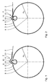
- An awning 1 according to the invention comprises an awning cloth 2 and a cloth shaft 3 for rolling up the awning cloth 2.
- the cloth shaft 3 extends in an axial direction along a longitudinal axis 8 about which it is rotatably mounted, and is hollow of a dimensionally stable material, preferably of aluminum or Plastic formed.
- the fabric shaft 3 has a piping rail 4 with a substantially round cross section.
- the piping rail 4 is formed as a groove extending parallel to the longitudinal axis 8 with a first boundary edge 5 and an opposite second boundary edge 6.
- the boundary edges 5, 6 are rounded. This prevents a risk of injury.
- the cloth shaft 3 has a round cross-section, in particular a circular outer contour and a radius R T on.
- a fastening device 7 is provided for fixing the awning fabric 2 to the fabric shaft 3.
- the fastening device 7 is reversible - as will be explained in more detail below - clamped in the piping rail 4.
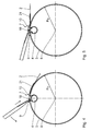
- the fastening device 7 will be described in more detail below. It comprises a first claw element 9 and a second claw element 10.
- the claw elements 9, 10 are for snapping the jamming Fastening device 7 in the piping rail 4 pivotally connected to each other.
- the fastening device 7 is designed as a profile part, in particular as a plastic profile part. It is preferably formed in one piece.
- the claw elements 9, 10 are connected by a flexible portion 11 with each other.
- a soft plastic or the design of the area are provided as a kind of film hinge.
- a multi-part design of the fastening device 7 is also possible. It is particularly conceivable to form the claw elements 9, 10 separately and to connect them together by means of a hinge.
- Each of the claw elements 9, 10 has an abutment region 12, which is provided in each case for abutment on one of the boundary edges 5, 6.
- the abutment region 12 is in each case arc-shaped and has two free ends 20 each. The free ends 20 come when inserting the fastening device 7 in the piping rail 4 on each opposite sides of one of the boundary edges 5, 6 to lie.
- the contact region 12 in each case has an essentially circular-arc-shaped section 13 with a radius of curvature r and a center of curvature M 1 , M 2 .
- the claw elements 9, 10 are made of a stiffer material than in the flexible region 11.
- a hard plastic is provided for the abutment region 12.
- the contact region 12 is adapted in its shape to the formation of the boundary edges 5, 6.
- the fastening device 7 thus lies in the jammed in the piping rail 4 surface on the fabric shaft 3, in particular at the boundary edges 5, 6 of the same.
- angle ⁇ is variable.
- the claw elements 9, 10 are in particular pivotable such that the connecting lines 14, 15 can be converted into an overstretched position. Under an overstretched position in this case is to be understood a position in which the connecting lines 14, 15 form an angle ⁇ > 180 °.
- the claw elements 9, 10 are thus connected by means of a joint, which can be converted into an over-center position. As a result, a secure snapping the claw elements 9, 10 is effected in the piping rail 4. An unintentional release of the fastening device 7 from the jammed in the piping rail 4 state is thereby reliably avoided.
- the first claw element 9 has a lever extension 17 arranged essentially along the first connecting line 14.
- the lever extension 17 adjoins the abutment region 12 of the first claw element 9.
- the lever extension 17 comprises, at its end facing the second claw element 10, the flexible region 11. It is also conceivable to design the entire lever extension 17 flexibly.
- the second claw element 10 has an extension 18, which forms a lever attachment for pivoting the claw elements 9, 10.
- the extension 18 also forms a stop for limiting the pivotability of the claw elements 9, 10 against each other.
- the extension 18 extends from the abutment region 12 of the second claw element 10 in the direction away from the second center of curvature M 2 .
- the second claw element 10 has an outer contour 19 with a curvature which is adapted to the radius R T of the roller tube 3.
- the second claw element 10 with the extension 18 covers the opening of the piping rail 4 in such a way that the circular outer contour of the cloth shaft 3 is completed by the fastening device 7.
- the second claw element 10 is connected to a welt flap 21.
- the Kederfahne 21 may advantageously be integrally formed with the second claw element 10. It is preferably flexible. As a material for the Kederfahne 21 in particular a soft plastic is provided. However, it is also conceivable to form the Kederfahne 21 of a stiffer material, in particular of a hard plastic.
- the welt flap 21 may in particular be made of the same material as the contact area 12.
- the Kederfahne 21 serves to attach the awning fabric 2 to the fastening device 7 and can be sewn to the awning fabric 2, welded, glued or riveted. Alternative attachment options, for example by means of a Velcro, are also possible.
- the Kederfahne 21 whose shape is adapted to the outer contour of the fabric shaft 3. It is preferably slightly curved, in particular circular arc section-shaped.
- the radius of curvature of the Kederfahne 21 corresponds to the radius R T of the fabric shaft.
- the awning fabric 2 on the concave that is arranged in the clamped in the piping rail 4 state of the fastening device 7 of the fabric shaft 3 side facing the Kederfahne 21.
- the hold of the awning fabric 2 is further improved because it is clamped between the Kederfahne 21 and the canvas shaft 3.
- the fastening device 7 may extend over the entire length of the roller tube 3 as a one-piece formed profile part.
- the fastening device 7 may extend over the entire length of the roller tube 3 as a one-piece formed profile part.
- the fastening device 7 is inserted into the piping rail 4 such that the first claw element 9 with the first boundary edge 5 of the piping rail 4 and the second claw element 10 with the second boundary edge 6 of Kederschiene 4 engages.
- the abutment regions 12 of the claw elements 9, 10 come into contact with the boundary edges 5, 6 of the welt rail 4.
- the angle ⁇ enclosed by the connecting lines 14, 15 is ⁇ 180 ° in this position.
- connection of the claw elements 9, 10 forming a toggle lever joint is overstretched, which leads to a snapping in of the fastening device 7.
- the claw elements 9, 10 are transferred in the piping rail 4 in an over-center position.
- the pivoting of the claw elements 9, 10 against each other limited by the stop, which is formed by the extension 18.
- the deformation of the flexible area 11 necessary for releasing the fastening device 7 counteracts the release of the fastening device 7.
- the fastening device 7 is thus secured against self-detachment from the piping rail 4.
- the fastening device 7 closes off the piping rail 4 watertight to the outside and follows substantially the outer contour of the fabric shaft 3.
- the fastening device 7 is only a few millimeters in the radial direction over the outer periphery of the fabric shaft 3 on. This allows a uniform, proper rolling of the awning fabric 2 on the fabric shaft. 3
- a lever such as a screwdriver, between the extension 18 and the first claw element 9 is inserted.
- the second claw element 10 is levered by means of the lever from the snapped position against the force exerted by the flexible portion 11 force in the open position.
- the voltage applied to the first boundary edge 5 first claw element 9 forms a pivot point, while the extension 18 forms a lever attachment for pivoting the claw elements 9, 10.
- a force is thus exerted in the radial direction outwards with respect to the longitudinal axis 8 on the claw elements 9, 10, in particular in the region of their connection for releasing the fastening device 7.
- the fastening device 7 is thus reversible in a simple manner in the piping rail 4 and snapped off the piping rail 4 again. In the snapped-in position, the fastening device 7 especially then secured against unintentional release of the piping rail 4 when the roller tube 3 is not stopped in time when rolling the awning fabric 2. In this case, the awning fabric 2 is rolled up again on the fabric shaft 3 only in the reverse winding direction. This is reversible by reversing the direction of rotation of the roller tube 3 in a simple manner.
- the fastening device 7 allows easy replacement of the awning fabric 2 of an awning. 1
Landscapes
- Engineering & Computer Science (AREA)
- Architecture (AREA)
- Structural Engineering (AREA)
- Civil Engineering (AREA)
- Building Awnings And Sunshades (AREA)
- Tents Or Canopies (AREA)
- Slide Fasteners (AREA)
- Seal Device For Vehicle (AREA)
Priority Applications (1)
| Application Number | Priority Date | Filing Date | Title |
|---|---|---|---|
| PL10162293T PL2267237T3 (pl) | 2009-06-04 | 2010-05-07 | Urządzenie mocujące |
Applications Claiming Priority (1)
| Application Number | Priority Date | Filing Date | Title |
|---|---|---|---|
| DE102009023835A DE102009023835B4 (de) | 2009-06-04 | 2009-06-04 | Befestigungs-Vorrichtung |
Publications (3)
| Publication Number | Publication Date |
|---|---|
| EP2267237A2 EP2267237A2 (de) | 2010-12-29 |
| EP2267237A3 EP2267237A3 (de) | 2013-08-07 |
| EP2267237B1 true EP2267237B1 (de) | 2016-03-30 |
Family
ID=43063340
Family Applications (1)
| Application Number | Title | Priority Date | Filing Date |
|---|---|---|---|
| EP10162293.4A Active EP2267237B1 (de) | 2009-06-04 | 2010-05-07 | Befestigungs-Vorrichtung |
Country Status (9)
| Country | Link |
|---|---|
| US (1) | US8490672B2 (pl) |
| EP (1) | EP2267237B1 (pl) |
| JP (1) | JP5645485B2 (pl) |
| CN (1) | CN101906856B (pl) |
| AU (1) | AU2010202229B2 (pl) |
| DE (1) | DE102009023835B4 (pl) |
| DK (1) | DK2267237T3 (pl) |
| ES (1) | ES2572370T3 (pl) |
| PL (1) | PL2267237T3 (pl) |
Cited By (1)
| Publication number | Priority date | Publication date | Assignee | Title |
|---|---|---|---|---|
| WO2025254546A1 (en) | 2024-06-07 | 2025-12-11 | Rekord Hale Namiotowe Spółka Z Ograniczoną Odpowiedzialnością | Portable sanitary unit |
Families Citing this family (13)
| Publication number | Priority date | Publication date | Assignee | Title |
|---|---|---|---|---|
| DE102006031336B4 (de) * | 2006-07-06 | 2010-08-05 | Airbus Deutschland Gmbh | Verfahren zur Herstellung eines Faserverbundbauteils in der Luft- und Raumfahrt |
| DE102006031325B4 (de) * | 2006-07-06 | 2010-07-01 | Airbus Deutschland Gmbh | Verfahren zur Herstellung eines Faserverbundbauteils für die Luft- und Raumfahrt |
| DE102006031323B4 (de) * | 2006-07-06 | 2010-07-15 | Airbus Deutschland Gmbh | Verfahren zur Herstellung eines Faserverbundbauteils für die Luft- und Raumfahrt |
| DE102006031334A1 (de) * | 2006-07-06 | 2008-01-10 | Airbus Deutschland Gmbh | Verfahren zur Herstellung eines Faserverbundbauteils für die Luft- und Raumfahrt |
| DE102006031326B4 (de) * | 2006-07-06 | 2010-09-23 | Airbus Deutschland Gmbh | Formkern und Verfahren zur Herstellung eines Faserverbundbauteils für die Luft- und Raumfahrt |
| USD735889S1 (en) | 2013-06-14 | 2015-08-04 | Schmitz-Werke Gmbh + Co. Kg | Awning holder |
| US9004574B1 (en) * | 2013-07-29 | 2015-04-14 | Carroll Fisher | E Z roller |
| JP6338987B2 (ja) * | 2014-09-17 | 2018-06-06 | 文化シヤッター株式会社 | 開閉装置 |
| US11021878B2 (en) | 2017-07-07 | 2021-06-01 | Thule Nv | Connection system and awning structure with connection system |
| CA3113938A1 (en) | 2020-04-06 | 2021-10-06 | Levolor, Inc. | Shade adapter for a roller shade |
| GB202008798D0 (en) * | 2020-06-10 | 2020-07-22 | Hunter Douglas Ind Bv | Connector and roller blind |
| JP7704562B2 (ja) * | 2021-04-30 | 2025-07-08 | 株式会社ニチベイ | ロールスクリーン及びロールスクリーンの製造方法 |
| IT202200023193A1 (it) * | 2022-11-10 | 2024-05-10 | Bega S R L Soc Benefit | Sistema a tenda avvolgibile e procedimento per rimuovere una tenda avvolgibile di un sistema a tenda avvolgibile |
Family Cites Families (33)
| Publication number | Priority date | Publication date | Assignee | Title |
|---|---|---|---|---|
| US536933A (en) * | 1895-04-02 | Curtain-roller | ||
| US286026A (en) * | 1883-10-02 | Curtain-roller attachment | ||
| US1492736A (en) * | 1923-01-30 | 1924-05-06 | Charles A Metzger | Awning |
| US2336189A (en) * | 1942-12-18 | 1943-12-07 | American Patents Syndicate Inc | Shade roller |
| US2547692A (en) * | 1947-06-30 | 1951-04-03 | Azzo Errol P D | Store awning |
| US2966206A (en) * | 1958-04-25 | 1960-12-27 | United Carr Fastener Corp | Organization and clip useful for installing furniture webbing |
| US3604073A (en) * | 1970-04-21 | 1971-09-14 | Harold Green | Releasable fastener assembly for webbing materials |
| DE2124264A1 (de) * | 1971-05-15 | 1972-11-30 | Wessel, Wolfgang', 2000 Hamburg | Rolljalousie |
| US3788216A (en) * | 1971-12-08 | 1974-01-29 | Dia Print Co Inc | Adjustable screen printing chase |
| US3757479A (en) * | 1971-12-27 | 1973-09-11 | Kamar Products Inc | Mirror |
| BE795313A (fr) * | 1972-02-15 | 1973-05-29 | Assael Marcel | Dispositif de fixation d'une feuille de revetement a l'interieur du diedre forme entre deux surfaces perpendiculaires |
| BE780464A (fr) * | 1972-03-10 | 1972-07-03 | Tombu Gerard | Perfectionnements aux profiles d'accrochage pour la fixation detissus muraux. |
| US3792510A (en) * | 1972-03-22 | 1974-02-19 | Griffolyn Company | Fastener |
| US3987835A (en) * | 1972-05-03 | 1976-10-26 | Frank D. Werner | Double cord edge fastener |
| DE2322635A1 (de) * | 1972-05-03 | 1973-11-22 | Werner Frank David | Befestigungseinrichtung fuer biegsame, duenne materialien |
| IL51474A (en) * | 1977-02-17 | 1979-09-30 | Peleg A | Fastening devices for flexible sheets |
| US4189880A (en) * | 1978-06-16 | 1980-02-26 | Gene Ballin | Combination mounting frame and film for a window |
| JPH0321439Y2 (pl) * | 1984-09-26 | 1991-05-09 | ||
| JPS6259227U (pl) * | 1985-10-01 | 1987-04-13 | ||
| US4799299A (en) * | 1987-12-28 | 1989-01-24 | Campbell Ken L | Clip track device for securing flexible sheets |
| FR2639879B2 (fr) * | 1988-01-26 | 1995-01-06 | Lefebvre Pascal | Perfectionnement a un chassis pour toile d'artiste peintre |
| US4991640A (en) * | 1988-04-29 | 1991-02-12 | Ontario Limited | Fastening means for fastening a flexible sheet to a body |
| EP0444218A1 (en) * | 1990-02-24 | 1991-09-04 | SUNCOVER s.r.l. | Roller for roller shades fitted with clamping means to secure an end of a web for shades to said roller |
| DE29507761U1 (de) * | 1994-05-16 | 1995-11-02 | Rossbach, Kurt, Dipl.-Ing., 73230 Kirchheim | Anordnung mit einer Markise o.dgl. |
| US5722723A (en) * | 1994-07-01 | 1998-03-03 | Presicent Partners, Lp | Stabilizing device for slipcovers |
| KR20010041032A (ko) * | 1998-02-20 | 2001-05-15 | 씨큐리티 이벤션즈 피티와이. 리미티드 | 스크린 어셈블리 |
| US7063124B2 (en) * | 2004-02-02 | 2006-06-20 | Lutron Electronics Co., Inc. | System for securing a shade fabric to a roller tube |
| US7614439B2 (en) * | 2004-10-05 | 2009-11-10 | Stephen Lukos | Roller tube having external slot for mounting sheet material |
| US7111662B2 (en) * | 2004-10-05 | 2006-09-26 | Stephen Lukos | Roller tube having external slot for mounting screen material |
| DE202006007416U1 (de) * | 2005-05-10 | 2006-09-21 | Kraler, Franz | Wickelwelle |
| AT8775U1 (de) * | 2005-05-10 | 2006-12-15 | Kraler Franz | Wickelwelle |
| JP4805661B2 (ja) * | 2005-11-24 | 2011-11-02 | 文化シヤッター株式会社 | 開閉装置 |
| FR2912456B1 (fr) * | 2007-02-12 | 2009-04-24 | Franciaflex | Jonc profile d'accrochage radial d'une toile de store |
-
2009
- 2009-06-04 DE DE102009023835A patent/DE102009023835B4/de not_active Expired - Fee Related
-
2010
- 2010-05-07 ES ES10162293T patent/ES2572370T3/es active Active
- 2010-05-07 EP EP10162293.4A patent/EP2267237B1/de active Active
- 2010-05-07 PL PL10162293T patent/PL2267237T3/pl unknown
- 2010-05-07 DK DK10162293.4T patent/DK2267237T3/en active
- 2010-05-31 AU AU2010202229A patent/AU2010202229B2/en active Active
- 2010-06-02 JP JP2010126722A patent/JP5645485B2/ja not_active Expired - Fee Related
- 2010-06-03 CN CN201010197415.4A patent/CN101906856B/zh not_active Expired - Fee Related
- 2010-06-04 US US12/793,950 patent/US8490672B2/en not_active Expired - Fee Related
Cited By (1)
| Publication number | Priority date | Publication date | Assignee | Title |
|---|---|---|---|---|
| WO2025254546A1 (en) | 2024-06-07 | 2025-12-11 | Rekord Hale Namiotowe Spółka Z Ograniczoną Odpowiedzialnością | Portable sanitary unit |
Also Published As
| Publication number | Publication date |
|---|---|
| EP2267237A3 (de) | 2013-08-07 |
| PL2267237T3 (pl) | 2016-08-31 |
| ES2572370T3 (es) | 2016-05-31 |
| JP5645485B2 (ja) | 2014-12-24 |
| DE102009023835B4 (de) | 2011-02-10 |
| EP2267237A2 (de) | 2010-12-29 |
| US8490672B2 (en) | 2013-07-23 |
| AU2010202229A1 (en) | 2010-12-23 |
| JP2010281196A (ja) | 2010-12-16 |
| CN101906856A (zh) | 2010-12-08 |
| AU2010202229B2 (en) | 2015-05-07 |
| US20100307694A1 (en) | 2010-12-09 |
| DK2267237T3 (en) | 2016-07-04 |
| CN101906856B (zh) | 2014-04-16 |
| DE102009023835A1 (de) | 2010-12-23 |
Similar Documents
| Publication | Publication Date | Title |
|---|---|---|
| EP2267237B1 (de) | Befestigungs-Vorrichtung | |
| DE3302159A1 (de) | Drosselklappenventil | |
| DE2517359A1 (de) | Bandmass | |
| EP1544379B1 (de) | Klemmvorrichtung | |
| DE3401435C2 (de) | Skistiefel | |
| WO1990013503A1 (de) | Profilleiste für eine warenbahn-ausbreitwalze | |
| DE2620522C3 (de) | Klemmvorrichtung für einen Schalungszuganker | |
| EP3317573B1 (de) | Schlauchklemme | |
| EP3141666A1 (de) | Wasserarmatur, insbesondere für einen wohnwagen, caravan, motorcaravan oder ein boot | |
| DE2552524B2 (de) | Absperrklappe | |
| EP4105432B1 (de) | Automatische dichtung mit einem führungselement zum führen einer schubstange und verfahren zum positionieren des führungselementes in einem gehäuse der dichtung | |
| EP2655141B1 (de) | Wischarm, insbesondere für eine scheibenwischvorrichtung eines kraftfahrzeugs | |
| DE1528040A1 (de) | Saege | |
| DE202008008250U1 (de) | Eckverbinder | |
| DE102006044207A1 (de) | Horizontal-Seitenspannvorrichtung für eine Seitenplane eines Nutzfahrzeugaufbaus | |
| DE102005046325B4 (de) | Vorrichtung zum Befestigen einer Wischerfunktionseinheit an einer Wischerwelle | |
| EP3000950B1 (de) | Wandkonsole für eine markise mit neigungsverstellung | |
| DE3731602A1 (de) | Gabelbaum | |
| DE202016104356U1 (de) | Vorrichtung zur Befestigung eines sanitären Bauteils, insbesondere eines Befestigungsrahmens für eine WC- oder Urinal-Betätigungsplatte | |
| DE19922260C1 (de) | Vorrichtung zur Sicherung und Entsicherung des aufgeweiteten Zustands einer Schelle aus einem ringförmig gebogenen Federstahlelement | |
| DE102015000490A1 (de) | Befestigungselement | |
| EP0902227B1 (de) | Einteiliges Gehäuse einer Schneckengewindeschelle | |
| DE2747153C2 (de) | Schwimmrahmen und/oder Bremsträger von Scheibenbremsen | |
| DE2110861C3 (de) | Schieberlüftung | |
| EP0388663B1 (de) | Rohrschelle |
Legal Events
| Date | Code | Title | Description |
|---|---|---|---|
| PUAI | Public reference made under article 153(3) epc to a published international application that has entered the european phase |
Free format text: ORIGINAL CODE: 0009012 |
|
| AK | Designated contracting states |
Kind code of ref document: A2 Designated state(s): AL AT BE BG CH CY CZ DE DK EE ES FI FR GB GR HR HU IE IS IT LI LT LU LV MC MK MT NL NO PL PT RO SE SI SK SM TR |
|
| AX | Request for extension of the european patent |
Extension state: BA ME RS |
|
| PUAL | Search report despatched |
Free format text: ORIGINAL CODE: 0009013 |
|
| AK | Designated contracting states |
Kind code of ref document: A3 Designated state(s): AL AT BE BG CH CY CZ DE DK EE ES FI FR GB GR HR HU IE IS IT LI LT LU LV MC MK MT NL NO PL PT RO SE SI SK SM TR |
|
| AX | Request for extension of the european patent |
Extension state: BA ME RS |
|
| RIC1 | Information provided on ipc code assigned before grant |
Ipc: E04F 10/06 20060101AFI20130703BHEP Ipc: E06B 9/44 20060101ALI20130703BHEP |
|
| 17P | Request for examination filed |
Effective date: 20131108 |
|
| RBV | Designated contracting states (corrected) |
Designated state(s): AL AT BE BG CH CY CZ DE DK EE ES FI FR GB GR HR HU IE IS IT LI LT LU LV MC MK MT NL NO PL PT RO SE SI SK SM TR |
|
| GRAP | Despatch of communication of intention to grant a patent |
Free format text: ORIGINAL CODE: EPIDOSNIGR1 |
|
| INTG | Intention to grant announced |
Effective date: 20151026 |
|
| GRAS | Grant fee paid |
Free format text: ORIGINAL CODE: EPIDOSNIGR3 |
|
| GRAA | (expected) grant |
Free format text: ORIGINAL CODE: 0009210 |
|
| AK | Designated contracting states |
Kind code of ref document: B1 Designated state(s): AL AT BE BG CH CY CZ DE DK EE ES FI FR GB GR HR HU IE IS IT LI LT LU LV MC MK MT NL NO PL PT RO SE SI SK SM TR |
|
| REG | Reference to a national code |
Ref country code: GB Ref legal event code: FG4D Free format text: NOT ENGLISH |
|
| REG | Reference to a national code |
Ref country code: CH Ref legal event code: EP |
|
| REG | Reference to a national code |
Ref country code: AT Ref legal event code: REF Ref document number: 785583 Country of ref document: AT Kind code of ref document: T Effective date: 20160415 |
|
| REG | Reference to a national code |
Ref country code: IE Ref legal event code: FG4D Free format text: LANGUAGE OF EP DOCUMENT: GERMAN |
|
| REG | Reference to a national code |
Ref country code: DE Ref legal event code: R096 Ref document number: 502010011311 Country of ref document: DE |
|
| REG | Reference to a national code |
Ref country code: FR Ref legal event code: PLFP Year of fee payment: 7 |
|
| REG | Reference to a national code |
Ref country code: ES Ref legal event code: FG2A Ref document number: 2572370 Country of ref document: ES Kind code of ref document: T3 Effective date: 20160531 |
|
| REG | Reference to a national code |
Ref country code: NL Ref legal event code: FP |
|
| REG | Reference to a national code |
Ref country code: SE Ref legal event code: TRGR |
|
| REG | Reference to a national code |
Ref country code: DK Ref legal event code: T3 Effective date: 20160627 |
|
| REG | Reference to a national code |
Ref country code: LT Ref legal event code: MG4D |
|
| PG25 | Lapsed in a contracting state [announced via postgrant information from national office to epo] |
Ref country code: HR Free format text: LAPSE BECAUSE OF FAILURE TO SUBMIT A TRANSLATION OF THE DESCRIPTION OR TO PAY THE FEE WITHIN THE PRESCRIBED TIME-LIMIT Effective date: 20160330 Ref country code: FI Free format text: LAPSE BECAUSE OF FAILURE TO SUBMIT A TRANSLATION OF THE DESCRIPTION OR TO PAY THE FEE WITHIN THE PRESCRIBED TIME-LIMIT Effective date: 20160330 Ref country code: NO Free format text: LAPSE BECAUSE OF FAILURE TO SUBMIT A TRANSLATION OF THE DESCRIPTION OR TO PAY THE FEE WITHIN THE PRESCRIBED TIME-LIMIT Effective date: 20160630 Ref country code: GR Free format text: LAPSE BECAUSE OF FAILURE TO SUBMIT A TRANSLATION OF THE DESCRIPTION OR TO PAY THE FEE WITHIN THE PRESCRIBED TIME-LIMIT Effective date: 20160701 |
|
| PG25 | Lapsed in a contracting state [announced via postgrant information from national office to epo] |
Ref country code: LV Free format text: LAPSE BECAUSE OF FAILURE TO SUBMIT A TRANSLATION OF THE DESCRIPTION OR TO PAY THE FEE WITHIN THE PRESCRIBED TIME-LIMIT Effective date: 20160330 Ref country code: LT Free format text: LAPSE BECAUSE OF FAILURE TO SUBMIT A TRANSLATION OF THE DESCRIPTION OR TO PAY THE FEE WITHIN THE PRESCRIBED TIME-LIMIT Effective date: 20160330 |
|
| PG25 | Lapsed in a contracting state [announced via postgrant information from national office to epo] |
Ref country code: EE Free format text: LAPSE BECAUSE OF FAILURE TO SUBMIT A TRANSLATION OF THE DESCRIPTION OR TO PAY THE FEE WITHIN THE PRESCRIBED TIME-LIMIT Effective date: 20160330 Ref country code: IS Free format text: LAPSE BECAUSE OF FAILURE TO SUBMIT A TRANSLATION OF THE DESCRIPTION OR TO PAY THE FEE WITHIN THE PRESCRIBED TIME-LIMIT Effective date: 20160730 |
|
| PG25 | Lapsed in a contracting state [announced via postgrant information from national office to epo] |
Ref country code: SM Free format text: LAPSE BECAUSE OF FAILURE TO SUBMIT A TRANSLATION OF THE DESCRIPTION OR TO PAY THE FEE WITHIN THE PRESCRIBED TIME-LIMIT Effective date: 20160330 Ref country code: PT Free format text: LAPSE BECAUSE OF FAILURE TO SUBMIT A TRANSLATION OF THE DESCRIPTION OR TO PAY THE FEE WITHIN THE PRESCRIBED TIME-LIMIT Effective date: 20160801 Ref country code: SK Free format text: LAPSE BECAUSE OF FAILURE TO SUBMIT A TRANSLATION OF THE DESCRIPTION OR TO PAY THE FEE WITHIN THE PRESCRIBED TIME-LIMIT Effective date: 20160330 Ref country code: CZ Free format text: LAPSE BECAUSE OF FAILURE TO SUBMIT A TRANSLATION OF THE DESCRIPTION OR TO PAY THE FEE WITHIN THE PRESCRIBED TIME-LIMIT Effective date: 20160330 Ref country code: RO Free format text: LAPSE BECAUSE OF FAILURE TO SUBMIT A TRANSLATION OF THE DESCRIPTION OR TO PAY THE FEE WITHIN THE PRESCRIBED TIME-LIMIT Effective date: 20160330 |
|
| PG25 | Lapsed in a contracting state [announced via postgrant information from national office to epo] |
Ref country code: LU Free format text: LAPSE BECAUSE OF FAILURE TO SUBMIT A TRANSLATION OF THE DESCRIPTION OR TO PAY THE FEE WITHIN THE PRESCRIBED TIME-LIMIT Effective date: 20160507 |
|
| REG | Reference to a national code |
Ref country code: DE Ref legal event code: R097 Ref document number: 502010011311 Country of ref document: DE |
|
| PLBE | No opposition filed within time limit |
Free format text: ORIGINAL CODE: 0009261 |
|
| STAA | Information on the status of an ep patent application or granted ep patent |
Free format text: STATUS: NO OPPOSITION FILED WITHIN TIME LIMIT |
|
| REG | Reference to a national code |
Ref country code: IE Ref legal event code: MM4A |
|
| 26N | No opposition filed |
Effective date: 20170103 |
|
| REG | Reference to a national code |
Ref country code: FR Ref legal event code: PLFP Year of fee payment: 8 |
|
| PG25 | Lapsed in a contracting state [announced via postgrant information from national office to epo] |
Ref country code: SI Free format text: LAPSE BECAUSE OF FAILURE TO SUBMIT A TRANSLATION OF THE DESCRIPTION OR TO PAY THE FEE WITHIN THE PRESCRIBED TIME-LIMIT Effective date: 20160330 Ref country code: IE Free format text: LAPSE BECAUSE OF NON-PAYMENT OF DUE FEES Effective date: 20160507 |
|
| REG | Reference to a national code |
Ref country code: FR Ref legal event code: PLFP Year of fee payment: 9 |
|
| PG25 | Lapsed in a contracting state [announced via postgrant information from national office to epo] |
Ref country code: HU Free format text: LAPSE BECAUSE OF FAILURE TO SUBMIT A TRANSLATION OF THE DESCRIPTION OR TO PAY THE FEE WITHIN THE PRESCRIBED TIME-LIMIT; INVALID AB INITIO Effective date: 20100507 Ref country code: CY Free format text: LAPSE BECAUSE OF FAILURE TO SUBMIT A TRANSLATION OF THE DESCRIPTION OR TO PAY THE FEE WITHIN THE PRESCRIBED TIME-LIMIT Effective date: 20160330 |
|
| PG25 | Lapsed in a contracting state [announced via postgrant information from national office to epo] |
Ref country code: MC Free format text: LAPSE BECAUSE OF FAILURE TO SUBMIT A TRANSLATION OF THE DESCRIPTION OR TO PAY THE FEE WITHIN THE PRESCRIBED TIME-LIMIT Effective date: 20160330 Ref country code: MT Free format text: LAPSE BECAUSE OF FAILURE TO SUBMIT A TRANSLATION OF THE DESCRIPTION OR TO PAY THE FEE WITHIN THE PRESCRIBED TIME-LIMIT Effective date: 20160330 Ref country code: TR Free format text: LAPSE BECAUSE OF FAILURE TO SUBMIT A TRANSLATION OF THE DESCRIPTION OR TO PAY THE FEE WITHIN THE PRESCRIBED TIME-LIMIT Effective date: 20160330 Ref country code: MK Free format text: LAPSE BECAUSE OF FAILURE TO SUBMIT A TRANSLATION OF THE DESCRIPTION OR TO PAY THE FEE WITHIN THE PRESCRIBED TIME-LIMIT Effective date: 20160330 |
|
| PG25 | Lapsed in a contracting state [announced via postgrant information from national office to epo] |
Ref country code: BG Free format text: LAPSE BECAUSE OF FAILURE TO SUBMIT A TRANSLATION OF THE DESCRIPTION OR TO PAY THE FEE WITHIN THE PRESCRIBED TIME-LIMIT Effective date: 20160330 |
|
| PG25 | Lapsed in a contracting state [announced via postgrant information from national office to epo] |
Ref country code: AL Free format text: LAPSE BECAUSE OF FAILURE TO SUBMIT A TRANSLATION OF THE DESCRIPTION OR TO PAY THE FEE WITHIN THE PRESCRIBED TIME-LIMIT Effective date: 20160330 |
|
| REG | Reference to a national code |
Ref country code: DE Ref legal event code: R082 Ref document number: 502010011311 Country of ref document: DE Representative=s name: RAU, SCHNECK & HUEBNER PATENTANWAELTE RECHTSAN, DE Ref country code: DE Ref legal event code: R081 Ref document number: 502010011311 Country of ref document: DE Owner name: MARKILUX GMBH + CO. KG, DE Free format text: FORMER OWNER: SCHMITZ-WERKE GMBH + CO KG, 48282 EMSDETTEN, DE |
|
| REG | Reference to a national code |
Ref country code: ES Ref legal event code: PC2A Owner name: MARKILUX GMBH + CO. KG Effective date: 20200731 |
|
| REG | Reference to a national code |
Ref country code: NL Ref legal event code: PD Owner name: MARKILUX GMBH + CO. KG; DE Free format text: DETAILS ASSIGNMENT: CHANGE OF OWNER(S), ASSIGNMENT; FORMER OWNER NAME: SCHMITZ-WERKE GMBH + CO. KG Effective date: 20200615 |
|
| REG | Reference to a national code |
Ref country code: BE Ref legal event code: PD Owner name: MARKILUX GMBH + CO. KG; DE Free format text: DETAILS ASSIGNMENT: CHANGE OF OWNER(S), CESSION; FORMER OWNER NAME: SCHMITZ-WERKE GMBH + CO. KG Effective date: 20200723 |
|
| REG | Reference to a national code |
Ref country code: CH Ref legal event code: PUE Owner name: MARKILUX GMBH + CO. KG, DE Free format text: FORMER OWNER: SCHMITZ-WERKE GMBH + CO. KG, DE |
|
| REG | Reference to a national code |
Ref country code: GB Ref legal event code: 732E Free format text: REGISTERED BETWEEN 20200917 AND 20200923 |
|
| P01 | Opt-out of the competence of the unified patent court (upc) registered |
Effective date: 20230516 |
|
| REG | Reference to a national code |
Ref country code: AT Ref legal event code: PC Ref document number: 785583 Country of ref document: AT Kind code of ref document: T Owner name: MARKILUX GMBH + CO. KG, DE Effective date: 20250110 |
|
| PGFP | Annual fee paid to national office [announced via postgrant information from national office to epo] |
Ref country code: NL Payment date: 20250522 Year of fee payment: 16 |
|
| PGFP | Annual fee paid to national office [announced via postgrant information from national office to epo] |
Ref country code: PL Payment date: 20250411 Year of fee payment: 16 |
|
| PGFP | Annual fee paid to national office [announced via postgrant information from national office to epo] |
Ref country code: GB Payment date: 20250522 Year of fee payment: 16 Ref country code: DK Payment date: 20250521 Year of fee payment: 16 Ref country code: ES Payment date: 20250616 Year of fee payment: 16 |
|
| PGFP | Annual fee paid to national office [announced via postgrant information from national office to epo] |
Ref country code: BE Payment date: 20250520 Year of fee payment: 16 Ref country code: IT Payment date: 20250530 Year of fee payment: 16 |
|
| PGFP | Annual fee paid to national office [announced via postgrant information from national office to epo] |
Ref country code: FR Payment date: 20250526 Year of fee payment: 16 |
|
| PGFP | Annual fee paid to national office [announced via postgrant information from national office to epo] |
Ref country code: CH Payment date: 20250601 Year of fee payment: 16 |
|
| PGFP | Annual fee paid to national office [announced via postgrant information from national office to epo] |
Ref country code: AT Payment date: 20250404 Year of fee payment: 16 |
|
| PGFP | Annual fee paid to national office [announced via postgrant information from national office to epo] |
Ref country code: SE Payment date: 20250522 Year of fee payment: 16 |
|
| PGFP | Annual fee paid to national office [announced via postgrant information from national office to epo] |
Ref country code: DE Payment date: 20250725 Year of fee payment: 16 |