EP2267213A1 - Haushaltsgerät mit Photokatalysator - Google Patents
Haushaltsgerät mit Photokatalysator Download PDFInfo
- Publication number
- EP2267213A1 EP2267213A1 EP10004093A EP10004093A EP2267213A1 EP 2267213 A1 EP2267213 A1 EP 2267213A1 EP 10004093 A EP10004093 A EP 10004093A EP 10004093 A EP10004093 A EP 10004093A EP 2267213 A1 EP2267213 A1 EP 2267213A1
- Authority
- EP
- European Patent Office
- Prior art keywords
- process air
- dryer according
- cabinet dryer
- laundry
- work space
- Prior art date
- Legal status (The legal status is an assumption and is not a legal conclusion. Google has not performed a legal analysis and makes no representation as to the accuracy of the status listed.)
- Granted
Links
Images
Classifications
-
- F—MECHANICAL ENGINEERING; LIGHTING; HEATING; WEAPONS; BLASTING
- F24—HEATING; RANGES; VENTILATING
- F24C—DOMESTIC STOVES OR RANGES ; DETAILS OF DOMESTIC STOVES OR RANGES, OF GENERAL APPLICATION
- F24C15/00—Details
- F24C15/20—Removing cooking fumes
- F24C15/2035—Arrangement or mounting of filters
-
- C—CHEMISTRY; METALLURGY
- C02—TREATMENT OF WATER, WASTE WATER, SEWAGE, OR SLUDGE
- C02F—TREATMENT OF WATER, WASTE WATER, SEWAGE, OR SLUDGE
- C02F1/00—Treatment of water, waste water, or sewage
- C02F1/30—Treatment of water, waste water, or sewage by irradiation
- C02F1/32—Treatment of water, waste water, or sewage by irradiation with ultraviolet light
-
- D—TEXTILES; PAPER
- D06—TREATMENT OF TEXTILES OR THE LIKE; LAUNDERING; FLEXIBLE MATERIALS NOT OTHERWISE PROVIDED FOR
- D06F—LAUNDERING, DRYING, IRONING, PRESSING OR FOLDING TEXTILE ARTICLES
- D06F58/00—Domestic laundry dryers
- D06F58/10—Drying cabinets or drying chambers having heating or ventilating means
-
- D—TEXTILES; PAPER
- D06—TREATMENT OF TEXTILES OR THE LIKE; LAUNDERING; FLEXIBLE MATERIALS NOT OTHERWISE PROVIDED FOR
- D06F—LAUNDERING, DRYING, IRONING, PRESSING OR FOLDING TEXTILE ARTICLES
- D06F58/00—Domestic laundry dryers
- D06F58/10—Drying cabinets or drying chambers having heating or ventilating means
- D06F58/14—Collapsible drying cabinets; Wall mounted collapsible hoods
-
- F—MECHANICAL ENGINEERING; LIGHTING; HEATING; WEAPONS; BLASTING
- F24—HEATING; RANGES; VENTILATING
- F24C—DOMESTIC STOVES OR RANGES ; DETAILS OF DOMESTIC STOVES OR RANGES, OF GENERAL APPLICATION
- F24C14/00—Stoves or ranges having self-cleaning provisions, e.g. continuous catalytic cleaning or electrostatic cleaning
-
- F—MECHANICAL ENGINEERING; LIGHTING; HEATING; WEAPONS; BLASTING
- F24—HEATING; RANGES; VENTILATING
- F24C—DOMESTIC STOVES OR RANGES ; DETAILS OF DOMESTIC STOVES OR RANGES, OF GENERAL APPLICATION
- F24C15/00—Details
- F24C15/20—Removing cooking fumes
- F24C15/2007—Removing cooking fumes from oven cavities
-
- B—PERFORMING OPERATIONS; TRANSPORTING
- B01—PHYSICAL OR CHEMICAL PROCESSES OR APPARATUS IN GENERAL
- B01D—SEPARATION
- B01D2255/00—Catalysts
- B01D2255/80—Type of catalytic reaction
- B01D2255/802—Photocatalytic
-
- C—CHEMISTRY; METALLURGY
- C02—TREATMENT OF WATER, WASTE WATER, SEWAGE, OR SLUDGE
- C02F—TREATMENT OF WATER, WASTE WATER, SEWAGE, OR SLUDGE
- C02F1/00—Treatment of water, waste water, or sewage
- C02F1/001—Processes for the treatment of water whereby the filtration technique is of importance
-
- C—CHEMISTRY; METALLURGY
- C02—TREATMENT OF WATER, WASTE WATER, SEWAGE, OR SLUDGE
- C02F—TREATMENT OF WATER, WASTE WATER, SEWAGE, OR SLUDGE
- C02F1/00—Treatment of water, waste water, or sewage
- C02F1/30—Treatment of water, waste water, or sewage by irradiation
-
- C—CHEMISTRY; METALLURGY
- C02—TREATMENT OF WATER, WASTE WATER, SEWAGE, OR SLUDGE
- C02F—TREATMENT OF WATER, WASTE WATER, SEWAGE, OR SLUDGE
- C02F2103/00—Nature of the water, waste water, sewage or sludge to be treated
- C02F2103/002—Grey water, e.g. from clothes washers, showers or dishwashers
-
- C—CHEMISTRY; METALLURGY
- C02—TREATMENT OF WATER, WASTE WATER, SEWAGE, OR SLUDGE
- C02F—TREATMENT OF WATER, WASTE WATER, SEWAGE, OR SLUDGE
- C02F2305/00—Use of specific compounds during water treatment
- C02F2305/08—Nanoparticles or nanotubes
-
- C—CHEMISTRY; METALLURGY
- C02—TREATMENT OF WATER, WASTE WATER, SEWAGE, OR SLUDGE
- C02F—TREATMENT OF WATER, WASTE WATER, SEWAGE, OR SLUDGE
- C02F2305/00—Use of specific compounds during water treatment
- C02F2305/10—Photocatalysts
-
- D—TEXTILES; PAPER
- D06—TREATMENT OF TEXTILES OR THE LIKE; LAUNDERING; FLEXIBLE MATERIALS NOT OTHERWISE PROVIDED FOR
- D06F—LAUNDERING, DRYING, IRONING, PRESSING OR FOLDING TEXTILE ARTICLES
- D06F58/00—Domestic laundry dryers
- D06F58/20—General details of domestic laundry dryers
- D06F58/206—Heat pump arrangements
-
- F—MECHANICAL ENGINEERING; LIGHTING; HEATING; WEAPONS; BLASTING
- F04—POSITIVE - DISPLACEMENT MACHINES FOR LIQUIDS; PUMPS FOR LIQUIDS OR ELASTIC FLUIDS
- F04D—NON-POSITIVE-DISPLACEMENT PUMPS
- F04D29/00—Details, component parts, or accessories
- F04D29/02—Selection of particular materials
- F04D29/023—Selection of particular materials especially adapted for elastic fluid pumps
-
- F—MECHANICAL ENGINEERING; LIGHTING; HEATING; WEAPONS; BLASTING
- F04—POSITIVE - DISPLACEMENT MACHINES FOR LIQUIDS; PUMPS FOR LIQUIDS OR ELASTIC FLUIDS
- F04D—NON-POSITIVE-DISPLACEMENT PUMPS
- F04D29/00—Details, component parts, or accessories
- F04D29/70—Suction grids; Strainers; Dust separation; Cleaning
Definitions
- the invention relates to a cabinet dryer for drying laundry and a method for operating such a cabinet dryer.
- Cabinet dryers for drying or conditioning the laundry are known in principle. They usually have a utility space for receiving the laundry and means to blow dry, heated air into the cabinet.
- Object of the present invention is to provide a cabinet dryer, which provides good treatment results. This object is achieved by claim 1.
- the cabinet dryer has a cooling and a heating device and a process circuit to lead the process air in a closed circuit through the work space and the cooling device and the heater over. This will dry and heat the air. Further, a heat pump is provided in order to save energy, the heater to heat and to cool the cooler. Finally, the cabinet dryer is also equipped with a steam generator.
- a steam generator which at first glance contradicts the drying of the process air by means of the cooling device and the heating device, has the advantage that the laundry can be moistened so as to avoid creasing and / or to effect a targeted sanitation.
- the atmosphere is preferably controlled by a climate sensor.
- the suspension means on process air channels, which can be connected to the process air circuit or connected to this.
- the process air ducts are designed so that they are able to promote process air with or without steam into the laundry inside. This allows the laundry to be dried more evenly.
- the suspension means comprise at least one hanger, which can be hung on a suspension in the cabinet.
- the suspension which may be configured, for example, as a clothes rail, has a process air circulation port connected to the process air circuit.
- the process air can be injected via the suspension in the utility room and / or in the hangers.
- the air ducts in the hangers can be connected to the process air circulation mouths so that process air can be blown into the hangers.
- the invention also relates to a method for operating such a cabinet dryer, in which the process air is introduced into the work space 1 at such a flow rate that the laundry begins to flutter. This further reduces wrinkling and improves the drying effect.
- the apparatus has a steam generator 18 for introducing steam into the process air.
- the steam generator 18 is arranged to introduce steam from below into the work space so that the steam (which is warmer than the process air) may rise up through the wash.
- the device and the textiles are preferably heated to at least 70 ° C and so sanitized. Heating in conjunction with the airflow removes the creases.
- the steaming of dry textiles since the slight moistening and heating by the steam greatly improves wrinkling and make another contribution to the refresher.
- a catch basin 20 for collecting condensed water. From there, the water can be automatically drained via a pumping device 21 or manually.
- the device described forms a substantially closed process air cycle, in which process air is passed back through the work space 1, the filter 5, the cooling device 7, the heater 8, past the UV light source 10 and the ceiling 14 back into the work space 1 ,
- the air is cooled to condense out moisture. Thereafter, the air in the heater 8 is reheated so that it can absorb new moisture.
- the cooling device 7 and the heating device 8 are operated by a heat pump (not shown).
- the condenser of the heat pump is thermally coupled to the heating device 8 and the evaporator to the cooling device 7.
- the fan 9 serves to circulate the air through the process air circuit.
- the UV light source 10 degrades organic compounds, either directly or via ozone formation. UV radiation at 185 nm generates ozone from the oxygen in the process air. Oxidizable substances are degraded in this way and permanently neutralized. If the UV light source produces light with a wavelength of e.g. 254 nm, it damages the DNA of cells and germs.
- UV light source instead of or in addition to the UV light source, it is also possible to provide an ozone generator which generates ozone, for example, via high electric fields.
- the UV light source or the ozone generator is followed by a sensor which measures the ozone concentration and regulates so that it does not exceed a predetermined value.
- the cabinet dryer preferably has a fragrance dispenser 24 for dispensing fragrances.
- a fragrance dispenser 24 for dispensing fragrances.
- it may be e.g. to act an absorbent material, which is impregnated with a fragrance, such as an essential oil.
- a fragrance such as an essential oil.
- the fragrance dispenser 24 can be arranged so that it emits a perfume directly into the working space 1, or he can also deliver it into the process air duct 6, preferably after the UV light source 10 and the ozone generator.
- the process air circuit is configured such that it introduces at least a portion of the process air from above into the work space 1. This happens in the execution after Fig. 1 over the openings 14.
- the process air is preferably introduced into the work space 1 at such a flow rate that the laundry begins to flutter.
- the air speed is set in a range of 2 .. 10m / s.
- the work space 1 is permanently connected to the environment via a small opening, so that the pressure in the interior of the work space substantially corresponds to the ambient pressure, so that the door 3 can be easily opened and closed.
- the remaining parts of the process air cycle are not connected to the environment.
- the cabinet dryer has means for degrading odors, such as those formed by bacteria.
- Suitable enzymes are, for example, hydrolases, in particular esterases, or oxireductases. Either the process air is replaced by a with the o.g. Enzyme displaced carrier material passed, or a finely divided in water enzyme mixture is fed to the process air stream.
- a photocatalyst and a light source for activating the photocatalyst may be provided, such as a photocatalyst comprising TiO 2 .
- the user can optionally control the means for degrading odors by a function on the control panel.
- Photocatalyst is understood to mean a substance which acts as a catalyst when illuminated with light of suitable wavelength, in particular visible or ultraviolet light.
- the photocatalyst is preferably a catalyst based on titanium oxide, ie a catalyst which contains, for example, TiO 2 (titanium dioxide); conceivable, however, are also catalysts based on CdS (cadmium sulfide), WO 3 (tungsten oxide) or ZO (zinc oxide).
- Suitable photocatalysts are, for example, in DE 20 2004 005 677 U1 and EP 1 205 244 described. They produce electrons and holes when absorbed by light, thereby inducing chemical reactions that degrade organic compounds and kill microorganisms and viruses.
- Particularly preferred are catalysts based on titanium dioxide due to the high efficiency and biocompatibility of this material.
- the product "Titan Shield ®” can be used as a photocatalyst.
- the suspension means comprise a suspension in the form of a clothes rail 28, which extends horizontally in the upper region of the work space through the latter and on which one or more clothes hangers 30 are suspended.
- each hanger 30 is equipped with a corresponding hook 31.
- the clothes rail 28 is hollow and connected to the ceiling portion 12 of the process air duct 6, so that process air flows into it. Furthermore, process air circulation openings 32, through which the process air can exit, are arranged on the clothes rail 28. At least a part of the process air circulation openings 32 is arranged at the top of the clothes rail 28.
- air ducts 34 which can be connected to the process air circuit to promote process air into the laundry.
- the air ducts 34 can be connected to the process air circulation openings 32.
- the air ducts 34 are connected to a plurality of openings 32 on the outside of the hangers 30, so that the process air entering from the clothes rail 28 can be directed into the laundry, for example in the sleeves and trouser legs.
- the shape of the air channels 34 may vary. They may be thin compared to the body of the hanger 30, or the hanger 30 may be e.g. be designed as a hollow body with a thin, perforated outer wall, whose whole interior forms an air duct.
- the hangers may also include other structures to which laundry may be hung.
- stapling devices or process air inflatable, perforated whole or partial body forms may be mentioned.
- These structures may also contain air ducts to introduce the process air into the laundry.
- the suspension means are designed so that they are also suitable to keep the laundry in a normal wardrobe, which is why a design as a hanger is particularly advantageous.
- the use of such suspension means simplifies handling for the user.
- the suspension means preferably hold the laundry in such a way that it can be well flown by the process air.
- the suspension means can also be designed so that they stretch the laundry, for example by weights, spring means or inflatable balloon body.
- suspension means can also be designed to keep the laundry items open at the top so that the process air flowing from above into the work space 1 can enter the laundry items directly.
- flexible hoses 40 can be provided (cf. Fig. 1 ), with which process air can be injected into the laundry.
- these hoses can be inserted directly and loosely into the laundry, as in Fig. 1 shown, or they may form part of the suspension means 26.
- Drying cabinets have several advantages over laundry tumblers. For example, eliminates the drive for the laundry drum. A simple, large-scale lint filter is sufficient because the laundry is not rolled. The air flow is not inhibited by multistage filters. The laundry hangs freely in the insulated cabinet and is supplied with dry air all around. As a result, it dries faster than in the tumble tumbler and is mechanically less stressed. The creasing is low, which ironing can be omitted or at least easier, which brings a further time and energy savings.
Landscapes
- Engineering & Computer Science (AREA)
- Chemical & Material Sciences (AREA)
- Combustion & Propulsion (AREA)
- Mechanical Engineering (AREA)
- General Engineering & Computer Science (AREA)
- Textile Engineering (AREA)
- Toxicology (AREA)
- Health & Medical Sciences (AREA)
- Chemical Kinetics & Catalysis (AREA)
- Life Sciences & Earth Sciences (AREA)
- Hydrology & Water Resources (AREA)
- Environmental & Geological Engineering (AREA)
- Water Supply & Treatment (AREA)
- Organic Chemistry (AREA)
- Accessory Of Washing/Drying Machine, Commercial Washing/Drying Machine, Other Washing/Drying Machine (AREA)
- Catalysts (AREA)
- Disinfection, Sterilisation Or Deodorisation Of Air (AREA)
- Detail Structures Of Washing Machines And Dryers (AREA)
Abstract
Description
- Die Erfindung betrifft einen Schranktrockner zum Trocknen von Wäsche sowie ein Verfahren zum Betrieb eines solchen Schranktrockners.
- Schranktrockner zum Trocknen oder Aufbereiten der Wäsche sind grundsätzlich bekannt. Sie besitzen in der Regel einen Nutzraum zur Aufnahme der Wäsche und Mittel, um trockene, erwärmte Luft in den Schrank einzublasen.
- Aufgabe der vorliegenden Erfindung ist es, einen Schranktrockner bereitzustellen, welcher gute Behandlungsresultate erbringt. Diese Aufgabe wird von Anspruch 1 erfüllt.
- Demgemäss besitzt der Schranktrockner eine Kühl- und eine Heizvorrichtung und einen Prozesskreislauf, um die Prozessluft in einem geschlossenen Kreislauf durch den Nutzraum und an der Kühlvorrichtung und der Heizvorrichtung vorbei zu führen. Dadurch wird die Luft getrocknet und erwärmt. Weiter ist eine Wärmepumpe vorgesehen, um in Energie sparender Weise die Heizvorrichtung zu heizen und die Kühlvorrichtung zu kühlen. Schliesslich ist der Schranktrockner auch mit einem Dampfgenerator ausgestattet. Die Verwendung eines Dampfgenerators, welche auf den ersten Blick an sich der Trocknung der Prozessluft mittels Kühlvorrichtung und Heizvorrichtung widerspricht, hat den Vorteil, dass die Wäsche angefeuchtet werden kann, um so Knitterbildung zu vermeiden und/oder eine gezielte Hygienisierung zu bewirken. Die Atmosphäre wird vorzugsweise mit einem Klimasensor geregelt.
- Vorzugsweise weisen die Aufhängemittel Prozessluftkanäle auf, welche an den Prozessluftkreislauf angeschlossen werden können oder an diesem angeschlossen sind. Die Prozessluftkanäle sind so ausgestaltet, dass sie in der Lage sind, Prozessluft mit oder ohne Dampf in die Wäsche hinein zu fördern. Dadurch kann die Wäsche gleichmässiger getrocknet werden.
- Vorzugsweise umfassen die Aufhängemittel mindestens einen Kleiderbügel, der an einer Aufhängung im Schrank aufgehängt werden kann. Die Aufhängung, welche beispielsweise als Kleiderstange ausgestaltet sein kann, weist eine mit dem Prozessluftkreislauf verbundene Prozessluftkreislaufmündung auf. Auf diese Weise kann die Prozessluft über die Aufhängung in den Nutzraum und/oder in die Kleiderbügel eingeblasen werden. Vorzugsweise können dabei die Luftkanäle in den Kleiderbügeln mit dem Prozessluftkreislaufmündungen verbunden werden, so dass Prozessluft in die Kleiderbügel eingeblasen werden kann.
- Die Erfindung betrifft auch ein Verfahren zum Betrieb eines solchen Schranktrockners, bei welchem die Prozessluft mit einer derartigen Strömungsgeschwindigkeit in den Nutzraum 1 eingeleitet wird, dass die Wäsche zu flattern beginnt. Dadurch wird die Knitterbildung weiter reduziert und die Trocknungswirkung verbessert.
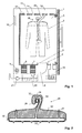
- Weitere Ausgestaltungen, Vorteile und Anwendungen der Erfindung ergeben sich aus den abhängigen Ansprüchen und aus der nun folgenden Beschreibung anhand der Figuren. Dabei zeigen:
-
Fig. 1 einen Schnitt durch eine Ausgestaltung eines Schranktrockners und -
Fig. 2 einen Schnitt durch eine Ausgestaltung eines Kleiderbügels. - Schranktrockner:
-
Fig. 1 zeigt einen Schnitt durch einen Schranktrockner mit einem Nutzraum 1 zur Aufnahme der Wäsche 2. Der Nutzraum 1 wird vorderseitig von einer Türe 3 verschlossen. Im Bodenbereich des Nutzraums befindet sich eine Öffnung 4, in welcher ein Filter 5 angeordnet ist, um Flusen zurückzuhalten. An die Öffnung 4 schliesst ein Prozessluftkanal 6 an, in welchem die Prozessluft über eine Kühlvorrichtung 7, eine Heizvorrichtung 8, einen Ventilator 9, vorbei an einer UV-Lichtquelle 10 in einen Deckenbereich 12 des Geräts geführt wird. Der Deckenbereich 12 ist über Öffnungen 14 in der Decke 15 des Nutzraums 1 mit dem Nutzraum 1 verbunden. - Weiter besitzt das Gerät einen Dampfgenerator 18 zum Einführen von Dampf in die Prozessluft. In der vorliegenden Ausführung ist der Dampfgenerator 18 so angeordnet, dass er Dampf von unten in den Nutzraum einleitet, so dass der Dampf (der wärmer als die Prozessluft ist) nach oben durch die Wäsche steigen kann. Mit dem Dampf werden das Gerät und die Textilien vorzugsweise auf mindestens 70°C erhitzt und so hygienisiert. Durch das Erwärmen in Verbindung mit dem Luftstrom werden die Knitter entfernt. Von besonderem Vorteil ist die Dampfbehandlung bei trockenen Textilien, da die leichte Befeuchtung und Erwärmung durch den Dampf das Entknittern stark verbessert und einen weiteren Beitrag zum Auffrischen leistet.
- Unterhalb der Kühlvorrichtung 7 befindet sich ein Auffangbecken 20 zum Auffangen von auskondensiertem Wasser. Von dort kann das Wasser automatisch über eine Pumpvorrichtung 21 oder manuell entleert werden.
- Das beschriebene Gerät bildet einen im Wesentlichen geschlossenen Prozessluftkreislauf, in welchem Prozessluft durch den Nutzraum 1, das Filter 5, die Kühlvorrichtung 7, die Heizvorrichtung 8, vorbei an der UV-Lichtquelle 10 und über die Decke 14 wieder zurück in den Nutzraum 1 geführt wird.
- Dabei werden im Filter 5 Flusen entfernt, die insbesondere die als Wärmetauscher ausgestalteten Kühlund Heizvorrichtungen 7 bzw. 8 verunreinigen könnten.
- In der Kühlvorrichtung 7 wird die Luft abgekühlt um Feuchte auszukondensieren. Danach wird die Luft in der Heizvorrichtung 8 wieder erwärmt, so dass sie neue Feuchtigkeit aufnehmen kann.
- Die Kühlvorrichtung 7 und die Heizvorrichtung 8 werden von einer Wärmepumpe betrieben (nicht gezeigt). Dabei ist der Kondensator der Wärmepumpe thermisch mit der Heizvorrichtung 8 gekoppelt und der Verdampfer mit der Kühlvorrichtung 7.
- Der Ventilator 9 dient dazu, die Luft durch den Prozessluftkreislauf umzuwälzen.
- Die UV-Lichtquelle 10 baut organische Verbindungen ab, entweder direkt oder über eine Ozonbildung. UV-Strahlung bei 185 nm erzeugt Ozon aus dem Sauerstoff der Prozessluft. Oxidierbare Laststoffe werden auf diese Weise abgebaut und dauerhaft neutralisiert. Erzeugt die UV-Lichtquelle Licht mit einer Wellenlänge von z.B. 254 nm, so schädigt sie die DNA von Zellen und Keimen.
- Anstelle der oder zusätzlich zur UV-Lichtquelle kann auch ein Ozongenerator vorgesehen sein, der Ozon beispielsweise über hohe elektrische Felder erzeugt.
- Vorzugsweise ist der UV-Lichtquelle bzw. dem Ozongenerator ein Sensor nachgeschaltet, der die Ozonkonzentration misst und so regelt, dass sie einen vorgegebenen Wert nicht übersteigt.
- Weiter besitzt der Schranktrockner vorzugsweise einen Duftspender 24 zur Abgabe von Duftstoffen. Dabei kann es sich in einer einfachen Ausführung z.B. um ein saugfähiges Material handeln, welches mit einem Duftstoff, beispielsweise einem ätherischen Öl, getränkt ist. Denkbar ist jedoch z.B. auch ein geheizter Verdampfer oder eine Sprühvorrichtung. Der Duftspender 24 kann so angeordnet sein, dass er ein Parfüm direkt in den Nutzraum 1 abgibt, oder er kann es auch in den Prozessluftkanal 6 abgeben, vorzugsweise nach der UV-Lichtquelle 10 bzw. dem Ozongenerator.
- Vorzugsweise ist der Prozessluftkreislauf so ausgestaltet, dass er mindestens einen Teil der Prozessluft von oben in den Nutzraum 1 einleitet. Dies geschieht in der Ausführung nach
Fig. 1 über die Öffnungen 14. - Um die Knitterbildung weiter zu reduzieren und die Trocknung zu verbessern, wird die Prozessluft vorzugsweise mit einer derartigen Strömungsgeschwindigkeit in den Nutzraum 1 eingeleitet, dass die Wäsche zu flattern beginnt. Von Vorteil wird die Luftgeschwindigkeit in einem Bereich von 2 .. 10m/s eingestellt.
- Vorzugsweise ist der Nutzraum 1 über eine kleine Öffnung permanent mit der Umgebung verbunden, so dass der Druck im Innern des Nutzraums im Wesentlichen dem Umgebungsdruck entspricht, so dass die Türe 3 einfach geöffnet und geschlossen werden kann. Die übrigen Teile des Prozessluftkreislaufs sind hingegen nicht mit der Umgebung verbunden.
- In einer bevorzugten Ausführung besitzt der Schranktrockner Mittel zum Abbauen von Geruchsstoffen, wie sie z.B. durch Bakterien gebildet werden.
- Dabei kann es sich beispielsweise um Mittel zum Beimischen von Enzymen handeln, mit denen Geruchsstoffe abgebaut werden. Geeignete Enzyme sind beispielsweise Hydrolasen, insbesondere Esterasen, oder Oxireduktasen. Entweder wird die Prozessluft durch ein mit den o.g. Enzymen versetztes Trägermaterial hindurchgeführt, oder eine in Wasser fein verteilte Enzymmischung wird dem Prozessluftstrom zugeführt.
- Alternativ oder zusätzlich hierzu kann auch ein Photokatalysator und eine Lichtquelle zum Aktivieren des Photokatalysator vorgesehen sein, wie z.B. ein Photokatalysator umfassend TiO2. Der Benutzer kann die Mittel zum Abbauen von Geruchsstoffen optional durch eine Funktion auf dem Bedienpanel steuern.
- Unter "Photokatalysator" wird ein Stoff verstanden, der bei Beleuchtung mit Licht geeigneter Wellenlänge, insbesondere sichtbarem oder ultraviolettem Licht, als Katalysator wirkt.
- Der Photokatalysator ist vorzugsweise ein Katalysator auf der Basis von Titanoxid, d.h. ein Katalysator, der z.B. TiO2 (Titandioxid) enthält, denkbar sind beispielsweise jedoch auch Katalysatoren basierend auf CdS (Kadmiumsulfid), WO3 (Wolframoxid) oder ZO (Zinkoxid). Geeignete Fotokatalysatoren sind beispielsweise in
DE 20 2004 005 677 U1 undEP 1 205 244 beschrieben. Sie erzeugen bei Lichtabsorption Elektronen und Löcher und induzieren dadurch chemische Reaktionen, welche organische Verbindungen abbauen und Mikroorganismen und Viren abzutöten vermögen. Besonders bevorzugt sind Katalysatoren auf der Basis von Titandioxid aufgrund der hohen Effizienz und biologischen Verträglichkeit dieses Materials. - Beispielsweise kann als Fotokatalysator das Produkt "Titan Shield®" eingesetzt werden.
- Denkbar ist ein Abbau von Geruchsstoffen auch mittels Oxidation, z.B. durch Zugabe von Ozon oder durch UV-Bestrahlung.
- Aufhängemittel:
- Um die Wäsche im Nutraum 1 aufzuhängen, sind Aufhängemittel 26 vorgesehen, wie sie beispielsweise in
Fig. 2 dargestellt sind. Diese Aufhängemittel sind vorzugsweise so ausgestaltet, dass sie einen Teil der Prozessluft in die Wäsche hinein fördern. - In der Ausführung nach
Fig. 2 umfassen die Aufhängemittel eine Aufhängung in Form einer Kleiderstange 28, welche sich horizontal im oberen Bereich des Nutzraums durch diesen erstreckt und an der ein oder mehrere Kleiderbügel 30 aufgehängt sind. Hierzu ist jeder Kleiderbügel 30 mit einem entsprechenden Haken 31 ausgestattet. - Die Kleiderstange 28 ist hohl ausgeführt und mit dem Deckenbereich 12 des Prozessluftkanals 6 verbunden, so dass Prozessluft in sie einströmt. Weiter sind an der Kleiderstange 28 Prozessluftkreislaufmündungen 32 angeordnet, durch welche die Prozessluft austreten kann. Mindestens ein Teil der Prozessluftkreislaufmündungen 32 ist an der Oberseite der Kleiderstange 28 angeordnet.
- Durch die Kleiderbügel 30 erstrecken sich Luftkanäle 34, welche an den Prozessluftkreislauf angeschlossen werden können, um Prozessluft in die Wäsche zu fördern. In der Ausführung nach
Fig. 2 können die Luftkanäle 34 an den Prozessluftkreislaufmündungen 32 angeschlossen werden. Hierzu münden die Luftkanäle 34 an der Unterseite der Haken 31 der Kleiderbügel 30, so dass durch Aufhängen der Kleiderbügel 30 an der Kleiderstange 28 die Luftkanäle 34 mit dem Prozessluftkreislauf verbunden werden können. - Die Luftkanäle 34 sind mit einer Vielzahl von Öffnungen 32 an der Aussenseite der Kleiderbügel 30 verbunden, so dass die von der Kleiderstange 28 in sie eintretende Prozessluft in die Wäsche geleitet werden kann, beispielsweise in Ärmel und Hosenbeine.
- Die Form der Luftkanäle 34 kann variieren. Sie können verglichen mit dem Körper des Kleiderbügels 30 dünn sein, oder der Kleiderbügel 30 kann z.B. als Hohlkörper mit dünner, perforierter Aussenwand ausgestaltet sein, dessen ganzes Inneres einen Luftkanal bildet.
- Anstelle von oder zusätzlich zu den Kleiderbügeln 30 können die Aufhängemittel auch noch andere Strukturen enthalten, an denen Wäsche aufgehängt werden kann. Beispielsweise seien Klammervorrichtungen oder von der Prozessluft aufblasbare, perforierte Ganz- oder Teilkörperformen genannt. Auch diese Strukturen können Luftkanäle enthalten, um die Prozessluft in die Wäsche einzuleiten.
- Vorzugsweise sind die Aufhängemittel so ausgestaltet, dass sie auch dazu geeignet sind, die Wäsche in einem normalen Kleiderschrank zu halten, weshalb eine Ausführung als Kleiderbügel besonders vorteilhaft ist. Durch die Verwendung derartiger Aufhängemittel wird die Handhabung für den Benutzer vereinfacht.
- Die Aufhängemittel halten die Wäsche vorzugsweise derart, dass sie gut von der Prozessluft beströmt werden kann.
- Zur Reduktion der Knitterbildung können die Aufhängemittel auch so ausgestaltet sein, dass sie die Wäsche strecken, beispielsweise durch Gewichte, Federmittel oder aufblasbare Ballonkörper.
- Weiter können die Aufhängemittel auch dazu ausgestaltet sein, die Wäschestücke nach oben offen zu halten, so dass die von oben in den Nutzraum 1 einströmende Prozessluft direkt in die Wäschestücke eintreten kann.
- Weiter können flexible Schläuche 40 vorgesehen sein (vgl.
Fig. 1 ), mit denen Prozessluft in die Wäsche eingeblasen werden kann. Diese Schläuche können z.B. direkt und lose in die Wäsche eingeführt werden, so wie inFig. 1 dargestellt, oder sie können Teil der Aufhängemittel 26 bilden. - Bemerkungen:
- Der hier beschriebene Schranktrockner kann zum Trocknen oder auch zum Aufbereiten von Wäsche verwendet werden. Unter "Aufbereiten" ist dabei nicht notwendigerweise ein Wasserentzug zu verstehen, sondern z.B. auch eine Hygienisierung und/oder Entknitterung (z.B. mittels Dampf bzw. UV- oder Ozongenerator) oder die Neutralisierung von Gerüchen (z.B. mit Hilfe der erwähnten Mitteln zum Beimischen von Enzymen oder mit dem UV- bzw. Ozongenerator).
- Im Vergleich zu Wäschetumblern haben Trockenschränke verschiedene Vorteile. Beispielsweise entfällt der Antrieb für die Wäschetrommel. Ein einfaches, grossflächiges Flusensieb genügt, weil die Wäsche nicht gewalkt wird. Der Luftstrom wird nicht gehemmt durch mehrstufige Filter. Die Wäsche hängt frei im isolierten Schrank und wird mit trockener Luft rundum angeströmt. Dadurch trocknet sie schneller als im Wäschetumbler und wird mechanisch weniger beansprucht. Die Knitterbildung ist gering, wodurch das Bügeln entfallen kann oder zumindest einfacher wird, was eine weitere Zeit- und Energieeinsparung mit sich bringt.
- Während in der vorliegenden Anmeldung bevorzugte Ausführungen der Erfindung beschrieben sind, ist klar darauf hinzuweisen, dass die Erfindung nicht auf diese beschränkt ist und in auch anderer Weise innerhalb des Umfangs der folgenden Ansprüche ausgeführt werden kann.
Claims (15)
- Schranktrockner zum Trocknen von Wäsche mit
einem Nutzraum (1) zur Aufnahme der Wäsche, einer Kühlvorrichtung (7) und einer Heizvorrichtung (8),
einem Prozessluftkreislauf, um Prozessluft in einem geschlossenen Kreislauf durch den Nutzraum (1) und an die Kühlvorrichtung (7) und die Heizvorrichtung (8) zu führen,
einer Wärmepumpe zum Kühlen der Kühlvorrichtung (7) und zum Heizen der Heizvorrichtung (8),
Aufhängemittel (26) zum Aufhängen der Wäsche im Nutzraum (1) und
einem Dampfgenerator (18) zum Einführen von Dampf in die Prozessluft. - Schranktrockner nach Anspruch 1, welcher eine UV-Lichtquelle (10) und/oder einen Ozongenerator aufweist.
- Schranktrockner nach einem der vorangehenden Ansprüche, welcher einen Duftspender (24) zur Abgabe eines Duftstoffs an die Prozessluft aufweist.
- Schranktrockner nach einem der vorangehenden Ansprüche, wobei der Prozessluftkreislauf dazu ausgestaltet ist, mindestens einen Teil der Prozessluft von oben in den Nutzraum (1) einzuleiten.
- Schranktrockner nach Anspruch 4, wobei in einer Decke (15) des Nutzraums (1) eine Vielzahl von Öffnungen (14) für die einströmende Prozessluft vorgesehen ist.
- Schranktrockner nach einem der vorangehenden Ansprüche, wobei der Dampfgenerator (18) dazu ausgestaltet ist, Dampf von unten in den Nutzraum (1) einzuleiten.
- Schranktrockner nach einem der vorangehenden Ansprüche, wobei die Aufhängemittel (26) Luftkanäle (34) aufweisen, welche an den Prozessluftkreislauf anschliessbar sind, um Prozessluft mit oder ohne Dampf in die Wäsche zu fördern.
- Schranktrockner nach einem der vorangehenden Ansprüche, wobei die Aufhängemittel (26) mindestens einen Kleiderbügel (30) aufweisen, der an einer Aufhängung (28) im Nutzraum (1) aufhängbar ist, wobei die Aufhängung (28) mindestens eine mit dem Prozessluftkreislauf verbundene Prozessluftkreislaufmündung (32) aufweist.
- Schranktrockner nach den Ansprüchen 6 und 7, wobei die Luftkanäle (34) an die Prozessluftkreislaufmündung bzw. -mündungen (32) anschliessbar sind.
- Schranktrockner nach Anspruch 9, wobei mindestens ein Teil der Prozessluftkreislaufmündungen jeweils an einer Oberseite der Aufhängung (28) angeordnet sind, und wobei mindesteins einige der Luftkanäle (34) an einer Unterseite eines in der Aufhängung (28) einhängbaren Hakens der Kleiderbügel (30) münden, derart, dass durch Aufhängen der Kleiderbügel (30) an der Aufhängung (28) die Luftkanäle (34) mit dem Prozessluftkreislauf verbindbar sind.
- Schranktrockner nach einem der vorangehenden Ansprüche, mit flexiblen Schläuchen (40), über welche Prozessluft in die Wäsche einblasbar ist.
- Schranktrockner nach einem der vorangehenden Ansprüche, wobei er Mittel zum Abbauen von Geruchsstoffen in der Prozessluft aufweist.
- Schranktrockner nach Anspruch 12, wobei die Mittel zum Abbauen von Geruchsstoffen in der Prozessluft umfassen:Mittel zum Beimischen von Enzymen zum Abbau von Geruchsstoffen, insbesondere Hydrolasen oder Oxireduktasen, aufweisen,und/oder einen Photokatalysator und eine Lichtquelle zum Aktivieren des Photokatalysators, insbesondere wobei der Photokatalysator TiO2 aufweist.
- Schranktrockner nach einem der vorangehenden Ansprüche, wobei der Nutzraum über eine Öffnung permanent mit der Umgebung verbunden ist, so dass ein Druck im Nutzraum einem Umgebungsdruck entspricht.
- Verfahren zum Betrieb des Schranktrockners nach einem der vorangehenden Ansprüche, wobei die Prozessluft mit einer derartigen Strömungsgeschwindigkeit in den Nutzraum (1) eingeleitet wird, dass die Wäsche zu flattern beginnt
Priority Applications (2)
| Application Number | Priority Date | Filing Date | Title |
|---|---|---|---|
| SI201031289A SI2267213T1 (sl) | 2010-01-28 | 2010-04-16 | Sušilna omara s toplotno črpalko |
| EP10004093.0A EP2267213B1 (de) | 2010-01-28 | 2010-04-16 | Schranktrockner mit Wärmepumpe |
Applications Claiming Priority (2)
| Application Number | Priority Date | Filing Date | Title |
|---|---|---|---|
| EP10000848A EP2213947A3 (de) | 2010-01-28 | 2010-01-28 | Haushaltgerät mit Photokatalysator |
| EP10004093.0A EP2267213B1 (de) | 2010-01-28 | 2010-04-16 | Schranktrockner mit Wärmepumpe |
Publications (2)
| Publication Number | Publication Date |
|---|---|
| EP2267213A1 true EP2267213A1 (de) | 2010-12-29 |
| EP2267213B1 EP2267213B1 (de) | 2016-07-06 |
Family
ID=41682850
Family Applications (3)
| Application Number | Title | Priority Date | Filing Date |
|---|---|---|---|
| EP10000848A Withdrawn EP2213947A3 (de) | 2010-01-28 | 2010-01-28 | Haushaltgerät mit Photokatalysator |
| EP10004093.0A Active EP2267213B1 (de) | 2010-01-28 | 2010-04-16 | Schranktrockner mit Wärmepumpe |
| EP10007322A Withdrawn EP2241826A1 (de) | 2010-01-28 | 2010-07-15 | Haushaltsgerät mit Photokatalysator |
Family Applications Before (1)
| Application Number | Title | Priority Date | Filing Date |
|---|---|---|---|
| EP10000848A Withdrawn EP2213947A3 (de) | 2010-01-28 | 2010-01-28 | Haushaltgerät mit Photokatalysator |
Family Applications After (1)
| Application Number | Title | Priority Date | Filing Date |
|---|---|---|---|
| EP10007322A Withdrawn EP2241826A1 (de) | 2010-01-28 | 2010-07-15 | Haushaltsgerät mit Photokatalysator |
Country Status (4)
| Country | Link |
|---|---|
| EP (3) | EP2213947A3 (de) |
| DK (1) | DK2267213T3 (de) |
| PL (1) | PL2267213T3 (de) |
| SI (1) | SI2267213T1 (de) |
Cited By (13)
| Publication number | Priority date | Publication date | Assignee | Title |
|---|---|---|---|---|
| EP2589700A1 (de) | 2013-01-29 | 2013-05-08 | V-Zug AG | Wäschebehandlungsschrank mit Kleiderbügel |
| US20180010289A1 (en) * | 2015-02-03 | 2018-01-11 | Koninklijke Philips N.V. | Garment care device for drying and sanitizing garments |
| DE102020118881A1 (de) | 2020-07-16 | 2022-01-20 | Steurer Trocknungs- und Aufbewahrungssysteme GmbH | Vorrichtung zum Trocknen und/oder zum Desinfizieren von Gegenständen |
| WO2022110447A1 (zh) * | 2020-11-27 | 2022-06-02 | 广州视源电子科技股份有限公司 | 衣物护理机及衣物护理机的温度控制方法 |
| WO2022214481A1 (de) | 2021-04-09 | 2022-10-13 | Miele & Cie. Kg | Wäschebehandlungsschrank mit einer vorrichtung zur behandlung der innenraumluft |
| WO2023029249A1 (zh) * | 2021-08-31 | 2023-03-09 | 无锡小天鹅电器有限公司 | 衣物护理设备 |
| EP4206384A1 (de) * | 2022-01-04 | 2023-07-05 | LG Electronics, Inc. | Aufhängevorrichtung |
| EP4206389A1 (de) * | 2022-01-04 | 2023-07-05 | LG Electronics, Inc. | Aufhängevorrichtung |
| DE102023110646A1 (de) | 2023-04-26 | 2024-10-31 | Miele & Cie. Kg | Wäschebehandlungsschrank mit einer Vorrichtung zum Behandeln der Prozessluft |
| WO2024223283A1 (de) | 2023-04-26 | 2024-10-31 | Miele & Cie. Kg | Wäschebehandlungsschrank mit einer vorrichtung zur konditionierung der innenraumluft |
| WO2024223280A1 (de) | 2023-04-26 | 2024-10-31 | Miele & Cie. Kg | Wäschebehandlungsschrank mit einer vorrichtung zum behandeln der prozessluft |
| DE102023110651A1 (de) | 2023-04-26 | 2024-10-31 | Miele & Cie. Kg | Wäschebehandlungsschrank mit einer Vorrichtung zur Konditionierung der Innenraumluft |
| US12144447B2 (en) | 2022-01-04 | 2024-11-19 | Lg Electronics Inc. | Hanger device |
Families Citing this family (13)
| Publication number | Priority date | Publication date | Assignee | Title |
|---|---|---|---|---|
| DE102011087583A1 (de) * | 2011-12-01 | 2013-06-06 | BSH Bosch und Siemens Hausgeräte GmbH | Haushaltsgerät mit einem Desodorierungssystem zum Entfernen geruchsaktiver Moleküle |
| EP2589699A1 (de) | 2013-01-29 | 2013-05-08 | V-Zug AG | Wäschebehandlungsschrank |
| EP2759633B1 (de) | 2013-01-29 | 2015-10-21 | V-Zug AG | Haushaltsgerät mit katalytischer Reinigung |
| EP2759632A1 (de) | 2013-01-29 | 2014-07-30 | V-Zug AG | Wäschebehandlungsschrank |
| DK2628842T3 (en) | 2013-05-06 | 2017-03-20 | V Zug Ag | Laundry Treatment Cabinet |
| CN104421987A (zh) * | 2013-08-26 | 2015-03-18 | 广东美的厨房电器制造有限公司 | 吸油烟机及其清洗喷管组件 |
| CN107743421B (zh) | 2015-06-11 | 2021-02-09 | 宝洁公司 | 用于将组合物施涂至表面的装置和方法 |
| CN107376638A (zh) * | 2017-09-19 | 2017-11-24 | 重庆净空居环保科技有限公司 | 发酵废气处理设备及处理方法 |
| CN109853201B (zh) * | 2017-11-30 | 2020-06-16 | 无锡小天鹅电器有限公司 | 干衣机以及干衣机用风道组件 |
| CN110318235B (zh) * | 2018-03-30 | 2023-07-21 | 青岛海尔洗衣机有限公司 | 一种干衣机 |
| CN111412496B (zh) * | 2019-01-04 | 2022-05-17 | 宁波方太厨具有限公司 | 一种集成式吸油烟机 |
| JP7453645B2 (ja) * | 2019-12-25 | 2024-03-21 | 青島海爾洗衣机有限公司 | 衣類処理装置 |
| WO2021139614A1 (zh) * | 2020-01-06 | 2021-07-15 | 青岛海尔滚筒洗衣机有限公司 | 滚筒洗衣机和用于滚筒洗衣机的蒸汽洗控制方法 |
Citations (8)
| Publication number | Priority date | Publication date | Assignee | Title |
|---|---|---|---|---|
| CH597822A5 (en) * | 1976-01-06 | 1978-04-14 | Daniel Ogiz | Clothes hanger for drying garments |
| EP0997573A1 (de) * | 1998-10-27 | 2000-05-03 | Carrera S.p.a. | Kleiderbügel |
| EP1205244A1 (de) | 1999-08-05 | 2002-05-15 | Kabushiki Kaisha Toyota Chuo Kenkyusho | Photokatalytisches material, photokatalytischer artikel und verfahren zu ihrer herstellung |
| US20030126691A1 (en) * | 2001-12-20 | 2003-07-10 | Gerlach Christian Gerhard Friedrich | Fabric article treating method and apparatus |
| US20050016012A1 (en) * | 2003-07-21 | 2005-01-27 | Samsung Electronics Co., Ltd. | Clothes dryer and method of controlling the same |
| DE202004005677U1 (de) | 2004-04-07 | 2005-05-19 | Kisch, Horst, Prof. Dr. | Kohlenstoffhaltiger Titandioxid-Photokatalysator |
| FR2919628A1 (fr) * | 2007-08-03 | 2009-02-06 | Lg Electronics Inc | Appareil de traitement de tissu. |
| WO2009064143A2 (en) * | 2007-11-16 | 2009-05-22 | Lg Electronics Inc. | Fabric treating machine |
Family Cites Families (17)
| Publication number | Priority date | Publication date | Assignee | Title |
|---|---|---|---|---|
| FR2739792B1 (fr) * | 1995-10-16 | 1997-12-26 | Seb Sa | Hotte a photocatalyse |
| JPH10235091A (ja) * | 1997-02-26 | 1998-09-08 | Hitachi Ltd | 乾燥機及び衣類乾燥機 |
| JPH1114072A (ja) * | 1997-06-24 | 1999-01-22 | Hitachi Home Tec Ltd | 加熱調理器 |
| JP2000296080A (ja) * | 1999-04-16 | 2000-10-24 | Matsushita Electric Ind Co Ltd | エアークリーナユニット |
| DE19935984A1 (de) * | 1999-07-30 | 2001-02-01 | Bsh Bosch Siemens Hausgeraete | Vorrichtung und Verfahren zum Desodorieren und Desinfizieren von Wäsche |
| WO2002076517A1 (en) * | 2001-03-27 | 2002-10-03 | Guido Ivo Tissi | Device for the sterilisation-purification of a fluid flow, in particular of a flow of compressed or forced air. |
| HK1050811A2 (en) * | 2002-05-09 | 2003-06-13 | 爱环保有限公司 | A fluid purification and disinfection device |
| GB0326256D0 (en) * | 2003-11-11 | 2003-12-17 | Lloyd Davy Dawn Y | Oven or utensil for cooking food |
| JP2005334617A (ja) * | 2004-04-30 | 2005-12-08 | Mediate:Kk | 布団,洗濯物等の乾燥方法および装置 |
| FR2873595B1 (fr) * | 2004-07-30 | 2007-06-29 | Brandt Ind Sas | Procede de traitement de composes organiques volatils ou gaz, notamment pour un conduit de circulation d'un flux d'air |
| JP4429954B2 (ja) * | 2005-03-31 | 2010-03-10 | リンナイ株式会社 | 食器洗浄機 |
| DE102005058662A1 (de) * | 2005-12-08 | 2007-06-14 | BSH Bosch und Siemens Hausgeräte GmbH | Verfahren zum Beseitigen von Gerüchen in einer Geschirrspülmaschine |
| EP1870114A1 (de) * | 2006-06-23 | 2007-12-26 | Global Engineering and Trade S.p.A. | Vorrichtung zur Luftreinigung mittels photokatalytischen Reaktionen |
| EP1925709A1 (de) * | 2006-11-23 | 2008-05-28 | Electrolux Home Products Corporation N.V. | Elektrisches Haushaltswaschgerät |
| KR101253179B1 (ko) * | 2006-12-14 | 2013-04-12 | 엘지전자 주식회사 | 건조기 |
| EP2113605B1 (de) * | 2008-04-23 | 2013-11-06 | Electrolux Home Products Corporation N.V. | Haushaltswasch- und/oder Trocknungsgerät und entsprechendes Betriebsverfahren |
| CN101608387B (zh) * | 2009-07-24 | 2011-01-12 | 合肥荣事达洗衣设备制造有限公司 | 一种可紫外杀菌洗涤的全自动洗衣机及其洗涤方法 |
-
2010
- 2010-01-28 EP EP10000848A patent/EP2213947A3/de not_active Withdrawn
- 2010-04-16 EP EP10004093.0A patent/EP2267213B1/de active Active
- 2010-04-16 DK DK10004093.0T patent/DK2267213T3/en active
- 2010-04-16 SI SI201031289A patent/SI2267213T1/sl unknown
- 2010-04-16 PL PL10004093T patent/PL2267213T3/pl unknown
- 2010-07-15 EP EP10007322A patent/EP2241826A1/de not_active Withdrawn
Patent Citations (8)
| Publication number | Priority date | Publication date | Assignee | Title |
|---|---|---|---|---|
| CH597822A5 (en) * | 1976-01-06 | 1978-04-14 | Daniel Ogiz | Clothes hanger for drying garments |
| EP0997573A1 (de) * | 1998-10-27 | 2000-05-03 | Carrera S.p.a. | Kleiderbügel |
| EP1205244A1 (de) | 1999-08-05 | 2002-05-15 | Kabushiki Kaisha Toyota Chuo Kenkyusho | Photokatalytisches material, photokatalytischer artikel und verfahren zu ihrer herstellung |
| US20030126691A1 (en) * | 2001-12-20 | 2003-07-10 | Gerlach Christian Gerhard Friedrich | Fabric article treating method and apparatus |
| US20050016012A1 (en) * | 2003-07-21 | 2005-01-27 | Samsung Electronics Co., Ltd. | Clothes dryer and method of controlling the same |
| DE202004005677U1 (de) | 2004-04-07 | 2005-05-19 | Kisch, Horst, Prof. Dr. | Kohlenstoffhaltiger Titandioxid-Photokatalysator |
| FR2919628A1 (fr) * | 2007-08-03 | 2009-02-06 | Lg Electronics Inc | Appareil de traitement de tissu. |
| WO2009064143A2 (en) * | 2007-11-16 | 2009-05-22 | Lg Electronics Inc. | Fabric treating machine |
Cited By (21)
| Publication number | Priority date | Publication date | Assignee | Title |
|---|---|---|---|---|
| EP2589700A1 (de) | 2013-01-29 | 2013-05-08 | V-Zug AG | Wäschebehandlungsschrank mit Kleiderbügel |
| US20180010289A1 (en) * | 2015-02-03 | 2018-01-11 | Koninklijke Philips N.V. | Garment care device for drying and sanitizing garments |
| DE102020118881A1 (de) | 2020-07-16 | 2022-01-20 | Steurer Trocknungs- und Aufbewahrungssysteme GmbH | Vorrichtung zum Trocknen und/oder zum Desinfizieren von Gegenständen |
| WO2022110447A1 (zh) * | 2020-11-27 | 2022-06-02 | 广州视源电子科技股份有限公司 | 衣物护理机及衣物护理机的温度控制方法 |
| BE1029286B1 (de) * | 2021-04-09 | 2022-11-16 | Miele & Cie | Wäschebehandlungsschrank mit einer Vorrichtung zur Behandlung der Innenraumluft |
| BE1029286A1 (de) | 2021-04-09 | 2022-11-07 | Miele & Cie | Wäschebehandlungsschrank mit einer Vorrichtung zur Behandlung der Innenraumluft |
| WO2022214481A1 (de) | 2021-04-09 | 2022-10-13 | Miele & Cie. Kg | Wäschebehandlungsschrank mit einer vorrichtung zur behandlung der innenraumluft |
| WO2023029249A1 (zh) * | 2021-08-31 | 2023-03-09 | 无锡小天鹅电器有限公司 | 衣物护理设备 |
| US12144447B2 (en) | 2022-01-04 | 2024-11-19 | Lg Electronics Inc. | Hanger device |
| EP4206384A1 (de) * | 2022-01-04 | 2023-07-05 | LG Electronics, Inc. | Aufhängevorrichtung |
| EP4206389A1 (de) * | 2022-01-04 | 2023-07-05 | LG Electronics, Inc. | Aufhängevorrichtung |
| US12590400B2 (en) | 2022-01-04 | 2026-03-31 | Lg Electronics Inc. | Hanger device configured to have at least one of a wind guard or a wind guard housing |
| US12492504B2 (en) | 2022-01-04 | 2025-12-09 | Lg Electronics Inc. | Hanger device |
| US12404625B2 (en) | 2022-01-04 | 2025-09-02 | Lg Electronics Inc. | Hanger device |
| DE102023110646A1 (de) | 2023-04-26 | 2024-10-31 | Miele & Cie. Kg | Wäschebehandlungsschrank mit einer Vorrichtung zum Behandeln der Prozessluft |
| BE1031553A1 (de) | 2023-04-26 | 2024-11-22 | Miele & Cie | Wäschebehandlungsschrank mit einer Vorrichtung zum Behandeln der Prozessluft |
| BE1031551A1 (de) | 2023-04-26 | 2024-11-22 | Miele & Cie | Wäschebehandlungsschrank mit einer Vorrichtung zur Konditionierung der Innenraumluft |
| BE1031551B1 (de) * | 2023-04-26 | 2024-12-02 | Miele & Cie | Wäschebehandlungsschrank mit einer Vorrichtung zur Konditionierung der Innenraumluft |
| DE102023110651A1 (de) | 2023-04-26 | 2024-10-31 | Miele & Cie. Kg | Wäschebehandlungsschrank mit einer Vorrichtung zur Konditionierung der Innenraumluft |
| WO2024223280A1 (de) | 2023-04-26 | 2024-10-31 | Miele & Cie. Kg | Wäschebehandlungsschrank mit einer vorrichtung zum behandeln der prozessluft |
| WO2024223283A1 (de) | 2023-04-26 | 2024-10-31 | Miele & Cie. Kg | Wäschebehandlungsschrank mit einer vorrichtung zur konditionierung der innenraumluft |
Also Published As
| Publication number | Publication date |
|---|---|
| EP2267213B1 (de) | 2016-07-06 |
| DK2267213T3 (en) | 2016-10-03 |
| PL2267213T3 (pl) | 2017-01-31 |
| SI2267213T1 (sl) | 2016-11-30 |
| EP2241826A1 (de) | 2010-10-20 |
| EP2213947A2 (de) | 2010-08-04 |
| EP2213947A3 (de) | 2010-10-06 |
Similar Documents
| Publication | Publication Date | Title |
|---|---|---|
| EP2267213B1 (de) | Schranktrockner mit Wärmepumpe | |
| EP2330247B1 (de) | Wäschetrockner, insbesondere Schranktrockner | |
| DE10030531B4 (de) | Verfahren und Vorrichtung zur bügelfreien Trocknung von feuchtem Gut, insbesondere von feuchter Wäsche bzw. Kleidung | |
| DE60301789T2 (de) | Wäschebehandlungsvorrichtung | |
| DE3343236C2 (de) | ||
| DE102009021040B4 (de) | Trockner und Steuerungsverfahren für diesen | |
| EP3817779A2 (de) | Verfahren und vorrichtung zur reinigung und desinfizierung von gegenständen | |
| DE102020115532A1 (de) | Vorrichtung und Verfahren zur Reinigung und Desinfizierung von Gegenständen, sowie Anwendung der Vorrichtung und des Verfahrens und damit gereinigte Gegenstände | |
| DE202012009608U1 (de) | Stylersystem für mehrere Kleidungsstücke | |
| DE4235560A1 (de) | Verfahren zum Entgiften, Lüften, Trocknen und Sterilisieren von Geweben und dergleichen sowie Gerät zur Durchführung des Verfahrens | |
| EP2759633B1 (de) | Haushaltsgerät mit katalytischer Reinigung | |
| EP1922443B1 (de) | Hausgerät mit einem strahler zum erzeugen eines ultravioletten lichtes | |
| DE102011087583A1 (de) | Haushaltsgerät mit einem Desodorierungssystem zum Entfernen geruchsaktiver Moleküle | |
| CN106263626A (zh) | 具有除湿杀菌熏香功能的衣柜 | |
| DE102017006768A1 (de) | Verfahren und Vorrichtung zum Behandeln von textilen Gegenständen | |
| DE202020101646U1 (de) | Vorrichtung zur Reinigung und Desinfizierung von Gegenständen, sowie Anwendung der Vorrichtung und damit gereinigte Gegenstände | |
| WO2007051456A1 (de) | Vorrichtung zum waschen und trocknen von wäsche in schrankform | |
| DE102010030441A1 (de) | Verfahren zur Bestimmung von wäschespezifischen Eigenschaften in einem Wäschebehandlungsgerät und hierfür geeignetes Wäschebehandlungsgerät | |
| EP2628842B1 (de) | Wäschebehandlungsschrank | |
| DE102018010294A1 (de) | Verfahren und Vorrichtung zur Reinigung und Desinfizierung von Textilien | |
| EP2759632A1 (de) | Wäschebehandlungsschrank | |
| CN206007639U (zh) | 一种衣柜除菌净味器 | |
| DE202018101763U1 (de) | Vorrichtung zur Reinigung und Desinfizierung von Gegenständen | |
| DE202005007406U1 (de) | Vorrichtung zur Reinigung und/oder Entkeimung von Matratzen | |
| DE102004012326A1 (de) | Verfahren und eine Vorrichtung zur Entfernung der Feuchte in flüssiger Form aus feuchten Gütern |
Legal Events
| Date | Code | Title | Description |
|---|---|---|---|
| PUAI | Public reference made under article 153(3) epc to a published international application that has entered the european phase |
Free format text: ORIGINAL CODE: 0009012 |
|
| AK | Designated contracting states |
Kind code of ref document: A1 Designated state(s): AT BE BG CH CY CZ DE DK EE ES FI FR GB GR HR HU IE IS IT LI LT LU LV MC MK MT NL NO PL PT RO SE SI SK SM TR |
|
| AX | Request for extension of the european patent |
Extension state: AL BA ME RS |
|
| 17P | Request for examination filed |
Effective date: 20110614 |
|
| GRAP | Despatch of communication of intention to grant a patent |
Free format text: ORIGINAL CODE: EPIDOSNIGR1 |
|
| RIC1 | Information provided on ipc code assigned before grant |
Ipc: D06F 58/14 20060101ALI20160226BHEP Ipc: D06F 58/20 20060101ALI20160226BHEP Ipc: D06F 58/10 20060101AFI20160226BHEP |
|
| INTG | Intention to grant announced |
Effective date: 20160323 |
|
| RIN1 | Information on inventor provided before grant (corrected) |
Inventor name: DOBER, ERNST Inventor name: HONEGGER, ADRIAN Inventor name: WERNER, JUERG |
|
| GRAS | Grant fee paid |
Free format text: ORIGINAL CODE: EPIDOSNIGR3 |
|
| GRAA | (expected) grant |
Free format text: ORIGINAL CODE: 0009210 |
|
| AK | Designated contracting states |
Kind code of ref document: B1 Designated state(s): AT BE BG CH CY CZ DE DK EE ES FI FR GB GR HR HU IE IS IT LI LT LU LV MC MK MT NL NO PL PT RO SE SI SK SM TR |
|
| REG | Reference to a national code |
Ref country code: GB Ref legal event code: FG4D Free format text: NOT ENGLISH |
|
| REG | Reference to a national code |
Ref country code: AT Ref legal event code: REF Ref document number: 810791 Country of ref document: AT Kind code of ref document: T Effective date: 20160715 Ref country code: CH Ref legal event code: NV Representative=s name: E. BLUM AND CO. AG PATENT- UND MARKENANWAELTE , CH Ref country code: CH Ref legal event code: EP |
|
| REG | Reference to a national code |
Ref country code: IE Ref legal event code: FG4D Free format text: LANGUAGE OF EP DOCUMENT: GERMAN |
|
| REG | Reference to a national code |
Ref country code: DE Ref legal event code: R096 Ref document number: 502010011932 Country of ref document: DE |
|
| REG | Reference to a national code |
Ref country code: DK Ref legal event code: T3 Effective date: 20160927 |
|
| REG | Reference to a national code |
Ref country code: NL Ref legal event code: FP |
|
| REG | Reference to a national code |
Ref country code: SE Ref legal event code: TRGR |
|
| REG | Reference to a national code |
Ref country code: LT Ref legal event code: MG4D |
|
| PG25 | Lapsed in a contracting state [announced via postgrant information from national office to epo] |
Ref country code: NO Free format text: LAPSE BECAUSE OF FAILURE TO SUBMIT A TRANSLATION OF THE DESCRIPTION OR TO PAY THE FEE WITHIN THE PRESCRIBED TIME-LIMIT Effective date: 20161006 Ref country code: IS Free format text: LAPSE BECAUSE OF FAILURE TO SUBMIT A TRANSLATION OF THE DESCRIPTION OR TO PAY THE FEE WITHIN THE PRESCRIBED TIME-LIMIT Effective date: 20161106 Ref country code: FI Free format text: LAPSE BECAUSE OF FAILURE TO SUBMIT A TRANSLATION OF THE DESCRIPTION OR TO PAY THE FEE WITHIN THE PRESCRIBED TIME-LIMIT Effective date: 20160706 Ref country code: LT Free format text: LAPSE BECAUSE OF FAILURE TO SUBMIT A TRANSLATION OF THE DESCRIPTION OR TO PAY THE FEE WITHIN THE PRESCRIBED TIME-LIMIT Effective date: 20160706 Ref country code: HR Free format text: LAPSE BECAUSE OF FAILURE TO SUBMIT A TRANSLATION OF THE DESCRIPTION OR TO PAY THE FEE WITHIN THE PRESCRIBED TIME-LIMIT Effective date: 20160706 |
|
| PG25 | Lapsed in a contracting state [announced via postgrant information from national office to epo] |
Ref country code: PT Free format text: LAPSE BECAUSE OF FAILURE TO SUBMIT A TRANSLATION OF THE DESCRIPTION OR TO PAY THE FEE WITHIN THE PRESCRIBED TIME-LIMIT Effective date: 20161107 Ref country code: GR Free format text: LAPSE BECAUSE OF FAILURE TO SUBMIT A TRANSLATION OF THE DESCRIPTION OR TO PAY THE FEE WITHIN THE PRESCRIBED TIME-LIMIT Effective date: 20161007 Ref country code: ES Free format text: LAPSE BECAUSE OF FAILURE TO SUBMIT A TRANSLATION OF THE DESCRIPTION OR TO PAY THE FEE WITHIN THE PRESCRIBED TIME-LIMIT Effective date: 20160706 Ref country code: LV Free format text: LAPSE BECAUSE OF FAILURE TO SUBMIT A TRANSLATION OF THE DESCRIPTION OR TO PAY THE FEE WITHIN THE PRESCRIBED TIME-LIMIT Effective date: 20160706 |
|
| REG | Reference to a national code |
Ref country code: DE Ref legal event code: R097 Ref document number: 502010011932 Country of ref document: DE |
|
| REG | Reference to a national code |
Ref country code: FR Ref legal event code: PLFP Year of fee payment: 8 |
|
| PG25 | Lapsed in a contracting state [announced via postgrant information from national office to epo] |
Ref country code: EE Free format text: LAPSE BECAUSE OF FAILURE TO SUBMIT A TRANSLATION OF THE DESCRIPTION OR TO PAY THE FEE WITHIN THE PRESCRIBED TIME-LIMIT Effective date: 20160706 Ref country code: RO Free format text: LAPSE BECAUSE OF FAILURE TO SUBMIT A TRANSLATION OF THE DESCRIPTION OR TO PAY THE FEE WITHIN THE PRESCRIBED TIME-LIMIT Effective date: 20160706 |
|
| PLBE | No opposition filed within time limit |
Free format text: ORIGINAL CODE: 0009261 |
|
| STAA | Information on the status of an ep patent application or granted ep patent |
Free format text: STATUS: NO OPPOSITION FILED WITHIN TIME LIMIT |
|
| PG25 | Lapsed in a contracting state [announced via postgrant information from national office to epo] |
Ref country code: SM Free format text: LAPSE BECAUSE OF FAILURE TO SUBMIT A TRANSLATION OF THE DESCRIPTION OR TO PAY THE FEE WITHIN THE PRESCRIBED TIME-LIMIT Effective date: 20160706 Ref country code: CZ Free format text: LAPSE BECAUSE OF FAILURE TO SUBMIT A TRANSLATION OF THE DESCRIPTION OR TO PAY THE FEE WITHIN THE PRESCRIBED TIME-LIMIT Effective date: 20160706 Ref country code: BG Free format text: LAPSE BECAUSE OF FAILURE TO SUBMIT A TRANSLATION OF THE DESCRIPTION OR TO PAY THE FEE WITHIN THE PRESCRIBED TIME-LIMIT Effective date: 20161006 Ref country code: SK Free format text: LAPSE BECAUSE OF FAILURE TO SUBMIT A TRANSLATION OF THE DESCRIPTION OR TO PAY THE FEE WITHIN THE PRESCRIBED TIME-LIMIT Effective date: 20160706 |
|
| 26N | No opposition filed |
Effective date: 20170407 |
|
| REG | Reference to a national code |
Ref country code: IE Ref legal event code: MM4A |
|
| PG25 | Lapsed in a contracting state [announced via postgrant information from national office to epo] |
Ref country code: MC Free format text: LAPSE BECAUSE OF FAILURE TO SUBMIT A TRANSLATION OF THE DESCRIPTION OR TO PAY THE FEE WITHIN THE PRESCRIBED TIME-LIMIT Effective date: 20160706 |
|
| PG25 | Lapsed in a contracting state [announced via postgrant information from national office to epo] |
Ref country code: LU Free format text: LAPSE BECAUSE OF NON-PAYMENT OF DUE FEES Effective date: 20170416 |
|
| REG | Reference to a national code |
Ref country code: BE Ref legal event code: MM Effective date: 20170430 |
|
| REG | Reference to a national code |
Ref country code: FR Ref legal event code: PLFP Year of fee payment: 9 |
|
| PG25 | Lapsed in a contracting state [announced via postgrant information from national office to epo] |
Ref country code: IE Free format text: LAPSE BECAUSE OF NON-PAYMENT OF DUE FEES Effective date: 20170416 |
|
| PG25 | Lapsed in a contracting state [announced via postgrant information from national office to epo] |
Ref country code: BE Free format text: LAPSE BECAUSE OF NON-PAYMENT OF DUE FEES Effective date: 20170430 |
|
| REG | Reference to a national code |
Ref country code: AT Ref legal event code: MM01 Ref document number: 810791 Country of ref document: AT Kind code of ref document: T Effective date: 20170416 |
|
| PG25 | Lapsed in a contracting state [announced via postgrant information from national office to epo] |
Ref country code: AT Free format text: LAPSE BECAUSE OF NON-PAYMENT OF DUE FEES Effective date: 20170416 |
|
| REG | Reference to a national code |
Ref country code: SI Ref legal event code: SP73 Owner name: V-ZUG AG; CH Effective date: 20180629 |
|
| PG25 | Lapsed in a contracting state [announced via postgrant information from national office to epo] |
Ref country code: MT Free format text: LAPSE BECAUSE OF FAILURE TO SUBMIT A TRANSLATION OF THE DESCRIPTION OR TO PAY THE FEE WITHIN THE PRESCRIBED TIME-LIMIT Effective date: 20160706 |
|
| PGFP | Annual fee paid to national office [announced via postgrant information from national office to epo] |
Ref country code: PL Payment date: 20190320 Year of fee payment: 10 |
|
| PG25 | Lapsed in a contracting state [announced via postgrant information from national office to epo] |
Ref country code: HU Free format text: LAPSE BECAUSE OF FAILURE TO SUBMIT A TRANSLATION OF THE DESCRIPTION OR TO PAY THE FEE WITHIN THE PRESCRIBED TIME-LIMIT; INVALID AB INITIO Effective date: 20100416 |
|
| PGFP | Annual fee paid to national office [announced via postgrant information from national office to epo] |
Ref country code: NL Payment date: 20190418 Year of fee payment: 10 |
|
| PGFP | Annual fee paid to national office [announced via postgrant information from national office to epo] |
Ref country code: DK Payment date: 20190425 Year of fee payment: 10 |
|
| PGFP | Annual fee paid to national office [announced via postgrant information from national office to epo] |
Ref country code: NO Payment date: 20190531 Year of fee payment: 12 |
|
| PG25 | Lapsed in a contracting state [announced via postgrant information from national office to epo] |
Ref country code: CY Free format text: LAPSE BECAUSE OF NON-PAYMENT OF DUE FEES Effective date: 20160706 |
|
| PGFP | Annual fee paid to national office [announced via postgrant information from national office to epo] |
Ref country code: GB Payment date: 20190418 Year of fee payment: 10 |
|
| PG25 | Lapsed in a contracting state [announced via postgrant information from national office to epo] |
Ref country code: MK Free format text: LAPSE BECAUSE OF FAILURE TO SUBMIT A TRANSLATION OF THE DESCRIPTION OR TO PAY THE FEE WITHIN THE PRESCRIBED TIME-LIMIT Effective date: 20160706 |
|
| PGFP | Annual fee paid to national office [announced via postgrant information from national office to epo] |
Ref country code: TR Payment date: 20200416 Year of fee payment: 11 |
|
| REG | Reference to a national code |
Ref country code: DK Ref legal event code: EBP Effective date: 20200430 |
|
| REG | Reference to a national code |
Ref country code: NL Ref legal event code: MM Effective date: 20200501 |
|
| PG25 | Lapsed in a contracting state [announced via postgrant information from national office to epo] |
Ref country code: FR Free format text: LAPSE BECAUSE OF NON-PAYMENT OF DUE FEES Effective date: 20200430 |
|
| GBPC | Gb: european patent ceased through non-payment of renewal fee |
Effective date: 20200416 |
|
| PG25 | Lapsed in a contracting state [announced via postgrant information from national office to epo] |
Ref country code: NL Free format text: LAPSE BECAUSE OF NON-PAYMENT OF DUE FEES Effective date: 20200501 |
|
| PG25 | Lapsed in a contracting state [announced via postgrant information from national office to epo] |
Ref country code: DK Free format text: LAPSE BECAUSE OF NON-PAYMENT OF DUE FEES Effective date: 20200430 Ref country code: GB Free format text: LAPSE BECAUSE OF NON-PAYMENT OF DUE FEES Effective date: 20200416 |
|
| PG25 | Lapsed in a contracting state [announced via postgrant information from national office to epo] |
Ref country code: PL Free format text: LAPSE BECAUSE OF NON-PAYMENT OF DUE FEES Effective date: 20200416 |
|
| P01 | Opt-out of the competence of the unified patent court (upc) registered |
Effective date: 20230502 |
|
| PGFP | Annual fee paid to national office [announced via postgrant information from national office to epo] |
Ref country code: IT Payment date: 20230426 Year of fee payment: 14 Ref country code: CH Payment date: 20230501 Year of fee payment: 14 |
|
| PGFP | Annual fee paid to national office [announced via postgrant information from national office to epo] |
Ref country code: SI Payment date: 20230406 Year of fee payment: 14 Ref country code: SE Payment date: 20230420 Year of fee payment: 14 |
|
| REG | Reference to a national code |
Ref country code: CH Ref legal event code: PL |
|
| REG | Reference to a national code |
Ref country code: SE Ref legal event code: EUG |
|
| PG25 | Lapsed in a contracting state [announced via postgrant information from national office to epo] |
Ref country code: CH Free format text: LAPSE BECAUSE OF NON-PAYMENT OF DUE FEES Effective date: 20240430 |
|
| PG25 | Lapsed in a contracting state [announced via postgrant information from national office to epo] |
Ref country code: IT Free format text: LAPSE BECAUSE OF NON-PAYMENT OF DUE FEES Effective date: 20240416 |
|
| PGFP | Annual fee paid to national office [announced via postgrant information from national office to epo] |
Ref country code: DE Payment date: 20250422 Year of fee payment: 16 |
|
| REG | Reference to a national code |
Ref country code: SI Ref legal event code: KO00 Effective date: 20240417 |
|
| PG25 | Lapsed in a contracting state [announced via postgrant information from national office to epo] |
Ref country code: SE Free format text: LAPSE BECAUSE OF NON-PAYMENT OF DUE FEES Effective date: 20240417 |