EP2260906B1 - Flammensperranordnung - Google Patents
Flammensperranordnung Download PDFInfo
- Publication number
- EP2260906B1 EP2260906B1 EP10005072.3A EP10005072A EP2260906B1 EP 2260906 B1 EP2260906 B1 EP 2260906B1 EP 10005072 A EP10005072 A EP 10005072A EP 2260906 B1 EP2260906 B1 EP 2260906B1
- Authority
- EP
- European Patent Office
- Prior art keywords
- flame arrester
- inserts
- arrangement according
- flame
- insert
- Prior art date
- Legal status (The legal status is an assumption and is not a legal conclusion. Google has not performed a legal analysis and makes no representation as to the accuracy of the status listed.)
- Active
Links
Images


Classifications
-
- A—HUMAN NECESSITIES
- A62—LIFE-SAVING; FIRE-FIGHTING
- A62C—FIRE-FIGHTING
- A62C4/00—Flame traps allowing passage of gas but not of flame or explosion wave
- A62C4/02—Flame traps allowing passage of gas but not of flame or explosion wave in gas-pipes
-
- A—HUMAN NECESSITIES
- A62—LIFE-SAVING; FIRE-FIGHTING
- A62C—FIRE-FIGHTING
- A62C4/00—Flame traps allowing passage of gas but not of flame or explosion wave
-
- A—HUMAN NECESSITIES
- A62—LIFE-SAVING; FIRE-FIGHTING
- A62C—FIRE-FIGHTING
- A62C2/00—Fire prevention or containment
-
- B—PERFORMING OPERATIONS; TRANSPORTING
- B01—PHYSICAL OR CHEMICAL PROCESSES OR APPARATUS IN GENERAL
- B01J—CHEMICAL OR PHYSICAL PROCESSES, e.g. CATALYSIS OR COLLOID CHEMISTRY; THEIR RELEVANT APPARATUS
- B01J19/00—Chemical, physical or physico-chemical processes in general; Their relevant apparatus
- B01J19/0006—Controlling or regulating processes
- B01J19/002—Avoiding undesirable reactions or side-effects, e.g. avoiding explosions, or improving the yield by suppressing side-reactions
-
- B—PERFORMING OPERATIONS; TRANSPORTING
- B01—PHYSICAL OR CHEMICAL PROCESSES OR APPARATUS IN GENERAL
- B01J—CHEMICAL OR PHYSICAL PROCESSES, e.g. CATALYSIS OR COLLOID CHEMISTRY; THEIR RELEVANT APPARATUS
- B01J2219/00—Chemical, physical or physico-chemical processes in general; Their relevant apparatus
- B01J2219/00049—Controlling or regulating processes
- B01J2219/00245—Avoiding undesirable reactions or side-effects
- B01J2219/00259—Preventing runaway of the chemical reaction
- B01J2219/00265—Preventing flame propagation
Definitions
- the invention relates to a flame arrester arrangement
- a flame arrester arrangement comprising a housing for holding at least two flame arrester inserts with a plurality of axial passage gaps dimensioned for a combustible gas and an intermediate layer disposed between two flame arrester inserts which provide a radial distribution of the flame arrestor emanating from a flame arrester insert and entering a downstream adjacent flame arrester insert Gas flow allowed.
- the flame arrester inserts of these flame arrester assemblies are predominantly produced in the winding process with thin stainless steel bands.
- a smooth metal strip is co-wound together with a uniformly corrugated metal strip and both form turns of a preferably disc-shaped arrangement.
- the passage gaps arise from the concerns of the corrugated metal strip on the two adjacent smooth metal bands, so that defined passage gaps arise. According to the flammability of the gas, the passage gaps may not exceed a predetermined gap cross-sectional area for a given axial length. In order to ensure a sufficient flow velocity for easily flammable gases, it may therefore be necessary to wind up the flame arrester inserts with a large cross-sectional area, that is to produce a large winding radius.
- the windings are preferably arranged spirally on top of each other, but may also consist of circular smooth turns each consisting of a smooth metal band and a corrugated metal band.
- the passage gaps do not align with each other so that the successive flame arrester inserts form resulting channels whose effective passage gaps are reduced in an undefined manner compared with the passage gaps of a flame arrester, because the free cross-sectional area of the stack of superimposed flame arrester inserts is reduced.
- the intermediate layers provided in the generic flame arrester arrangement thus serve as spacers which prevent a reduction in the free cross-sectional area of the flame arrester inserts lying one behind the other.
- the housing of the flame arrester arrangement forms an enclosing cage with a closed jacket wall.
- a flame arrester arrangement of the type described is known from WO 94/00197 A1 known. It consists of several flame arresters, between which an intermediate layer of wing-like deflecting elements is inserted. The entire assembly is inserted in a tubular housing. Since the flame arrester inserts are formed in this case by circularly closed turns of each a smooth metal band and a corrugated metal strip, it is also essential for this construction that they are so small gaps between the flame arrester insert and the housing that through them no appreciable gas flow around the Flame arrester can take place around. Accordingly, here too, the flame arrester insert must be fitted so tightly into the enclosing cage that it can not practically be removed for cleaning and renewal purposes.
- a similar problem exists with a detonation fuse, as by the AT 7 424 U1 is known.
- a pair of flame arresters is combined to form a flame arrester insert and inserted into a strapping tube.
- the strapping tube causes a seal to a surrounding wall of a housing. Consequently, the flame arrester inserts must be sealed against the strapping tube and the strapping tube must be sealingly pressed into the housing. Again, a simple removal of such a flame arrester insert is not possible.
- radially outer support rings can directly rest axially on the outside of the flame arrester inserts, so that a radially outer flow through the gas passing through the flame arrester arrangement is not possible.
- a stepped cage encapsulation cage with each flame arrester set sealingly resting on the metal of the containment cage.
- the production of such a cage cage is very expensive and can not be done in series, since depending on the number of flame arresters different models and diameters are necessary.
- the flame arrester inserts must be made in different sizes.
- the invention is therefore based on the object, a flame arrester arrangement of the type mentioned in such a way that facilitates the assembly and disassembly of the flame arrester inserts, especially when using three or more flame arresters and an unintended flow around the flame arrester inserts is safely avoided.
- a flame arrester arrangement of the type mentioned above is characterized in that radially outward of the flame arrester inserts a space facilitating the expansion of Flommensperrnieses space is provided and at least a separate closed seal between a flame arrester and the housing or between two flame arrester inserts is arranged so that a flow around the flame arrester is prevented in the radial space located outside of the passage gaps.
- the flame arrester arrangement according to the invention can thus have an arbitrarily large space radially outward of the passage gaps of the flame arrester inserts, so that a simple assembly and disassembly of the flame arrestor sets is possible.
- the space between the housing and the flame arrester insert may be closed by the seal for axial flow therethrough.
- the seals provided radially on the outside of the flame arrester inserts may form each other axially without any gaps, so that they are clamped between axially clamped housing points and thus a radial one. Seal against the leakage of gas from the liners effect.
- the seals are formed by spirally wound turns of a smooth metal strip, so that the application of the seal after the production of the flame arrester insert, preferably in the winding technique, can take place.
- the smooth metal strip used for the production of the seal may have the width of the metal strip of the flame arrester insert or a greater width (axial length with respect to the flame arrestor) corresponding to the common axial length of the flame arrester insert and intermediate layer. If the width of the metal strip for the wound gasket is equal to the width of the metal bands for the production of the flame arrester insert, an intermediate ring is expediently inserted between the wound gaskets in the intermediate layer, so that in the axial direction, the wound gaskets and the intermediate rings form a length which Length of the flame arrester inserts with their intermediate layers corresponds.
- a closed seal may be disposed between the radial edges of the flame arrester inserts so that sealing occurs radially outward between the flame arrester inserts.
- the intermediate layer is formed smaller by the radial width of the closed seal, so that the intermediate layer between the flame arrester inserts and the sealing ring located therebetween can be inserted.
- An advantageous embodiment of the flame arrester according to the invention is achieved with flame arrester inserts, which are provided radially outside of the passage gaps with a circumferential solid edge, wherein the edges are clamped as a stack between the axially mutually braced housing parts. The sealing radially outward thus takes place by the juxtaposed and mutually braced massive edges of the flame arrester inserts. Between the edges and ring seals can be inserted, which then an axial tension of the edges of the flame arrester inserts can make unnecessary.
- the flame arrester inserts are provided with corresponding solid edges, so that the flame arrester inserts in this case no longer need to be surrounded by an additional jacket housing. As a result, the flame arrester inserts can be easily removed for service purposes, after only possibly tightening screws for the axial clamping of housing parts have been loosened or removed.
- the intermediate layer may be formed, for example, by a wire mesh, which merely serves as a spacer between the flame arrester inserts.
- the intermediate layers by spot welding, soldering u. ⁇ . Be connected to an associated flame arrester insert.
- the intermediate ring by welding, soldering u. ⁇ . To connect with the adjacent seal of the flame arrester insert.
- the present invention is preferably realized with wound flame arrester inserts. It is of course also feasible with all other conventional flame arrester inserts, for example, with sintered metal flame arrester inserts, metal foams, Drahtgewebegittern, expanded metal mesh, porous ceramics, drilled plates made of metal or plastic (especially PTFE) o. The like ..
- FIG. 1 allows a housing 1 with two flange-like housing parts 2, 3 recognize, which can be clamped together axially (not shown) clamping screws.
- the flange-like housing parts 2, 3 act on housing rings 4, 5 connected to them, between which four flame arrester inserts 6 each having an intermediate layer 7 are inserted axially.
- the housing rings 4, 5 have on their radially outwardly facing lateral surface circumferential grooves 8, are inserted into the sealing rings 9 in the form of O-rings.
- a cylindrical jacket wall 10 is pushed, which seals the space for the flame arrester inserts 6 with the sealing rings 9.
- the flame arrester inserts end radially at a distance from the cylindrical casing wall 10 and are provided on their outer side with closed seals 11 whose axial length corresponds to the sum of the axial lengths of the flame arrester insert with associated intermediate layer 7.
- the seals 11 are preferably formed by spiral turns of a metal strip in the width of the axial length of the seal 11.
- the wound winding package for the seal 11 is chosen so large that the overlap area F, ie the radial thickness of the seal 11, is so great that the seals 11 can absorb the clamping pressure.
- FIG. 1 It is in FIG. 1 It can be seen that radially outside of the seals 11, a radially outer gap 12 can exist to the cylindrical jacket wall, since the sealing in the radial direction over the axial length of the package of flame arrester inserts 6 with the intermediate layers 7 takes place reliably.
- the seals 11 have an axial length corresponding to the axial length of the flame arrester inserts 6.
- sealing intermediate rings 13 are inserted, which ensure that the stack of seals 11 and sealing intermediate rings 13 has the axial length, which have on the flame arrester inserts 6 with the intermediate layers 7.
- FIG. 2a illustrates that between the seal intermediate ring 13 and formed as a wire mesh liner 7, a weld joint 14 is provided so that the intermediate layer 7 with the seal intermediate ring 13 is uniformly handled.
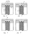
- FIG. 3 In the variant according to FIG. 3 are between the housing rings 4, 5 clamped two flame arresters 6 with a schematically indicated intermediate layer 7, wherein the intermediate layer 7 has a radial extent which is slightly smaller than the radial extent of the flame arrester inserts 6.
- a sealing ring 15 In the remaining radial edge region of the flame arrester inserts is a sealing ring 15 as a metallic flat gasket.
- FIG. 4 shows in a view the formation of the intermediate layer 7, which is in the form of a wire mesh here uniformly connected to the sealing ring 15, for example by welding.
- FIG. 5 embodiment shown are between the housing rings 4, 5 three flame arrester inserts 6 are arranged with two interposed intermediate layers 7 and axially braced.
- the cylindrical jacket wall 10 has here on its inside three circumferential grooves 16, are inserted into the sealing rings 17, which close the radially outer gap 12 in the axial direction for a flow. Accordingly, although gas can enter the radially outer gap from the intermediate layer, but does not flow around one of the flame arrester inserts 6 on the outside, since the axial passage through the sealing rings 17 is blocked.
- FIG. 6 shows a similar arrangement in which only the middle flame arrestor 6 is completed with a sealing ring 17 radially outward. This is sufficient if the system of the housing rings 4, 5 to the radial Edges of the outer flame arrester inserts 6 is designed to be sealing, so that already by the tension of the outer flame arrester inserts 6, a flow around the outer flame arrester inserts 6 is not possible. The sealing ring 17 therefore serves to prevent the flow around the middle flame arrester insert 6.
- FIG. 7 shows one of the FIG. 5 similar arrangement in which sealing rings 17 'are not designed as flat sealing rings, but as sealing rings with a circular cross section in the manner of an O-ring.
- a corresponding modification of the embodiment according to FIG. 6 can be found in FIG. 8 .
- the formation of the sealing rings 17, 17 ' is preferably made of a soft metal, for example soft copper.
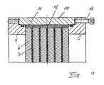
- FIG. 9 illustrated embodiment of a flame arrester arrangement provides that in the housing ring 5 a bolt screw 18 is screwed, which is supported with its blunt end to a front side of the cylindrical shell wall 10.
- the housing ring 5 has a plurality of such bolts bolts 18, which facilitate the disassembly of the flame arrester arrangement.
- the bolt 18, namely, the housing ring 5 can be deducted from the cylindrical shell wall 10 by screws, whereby the access to the arrangement of the flame arrester inserts 6, the intermediate layers 7 and the seals 11 is free. Since the outer radial gap 12 is provided to the cylindrical jacket wall, the flame arrester inserts 6 with the intermediate layers 7 and the seals 11 can be removed individually or together in a simple manner and clean or replace for service purposes.
- the flame arrester inserts 6 shown in the previous embodiments consist of spiral or concentric, adjacent turns, each of a smooth metal band and a corrugated Metal band exist.
- the corrugated metal strip is preferably designed with corrugations that are oblique to the longitudinal direction of the strip.
- the opposite hatching in the drawings expresses that to equalize the flow through the flame arrester inserts 6 with different directions wound flame arresters join each other, so that the gas flows through the package of flame arrester inserts in the manner of a zig-zag course, because through the corrugated Band caused passage gaps in different oblique directions.
- the flame arrester inserts 6 ' are provided with a circumferential solid edge 19 having on one side a circumferential open groove for receiving a seal 20.
- the housing ring 4, 5 are provided with lugs 21 which have openings for passing a clamping screw 22.
- the clamping screw 22 is located on one of the lugs 21 with a screw head 23 and the other of the lugs 21 with a nut surrounding the bolt 24, so that by means of several such, distributed over the circumference clamping screws 22, the housing rings 4, 5 are axially drawn together and clamp the stack formed from the flame arrester inserts 6 'between them.
- Each of the flame arrester inserts 6 ' is according to the embodiment FIG. 10 stabilized with a radially drilled through them bolt. Such stabilization of flame arrester inserts 6 'is basically known for large, wound flame arrester inserts 6'.
- FIG. 11 shows two variants for the execution of the clamping screw 22 in conjunction with the housing rings 4, 5 to perform the axial strain.
- the clamping screw extends through through holes in the solid edges 19 of the flame arrester inserts 6 ', whereby an additional alignment of the flame arrester inserts 6' is ensured.
- FIG. 12 eight flame arrester inserts 6 are provided, which are arranged between housing rings 4, 5.
- the cylindrical jacket wall 10 is connected by welds 26 to the housing 1.
- the seals 11 'are according to FIG. 12a executed in an axial length corresponding to the summed axial length of two flame arrester inserts 6 and two intermediate layers 7.
- four closed seals 11 'are thus used, which are clamped between the housing rings 4, 5.
- radial bolt sections 25' are introduced, which are preferably introduced by receiving the defined passage gaps of the flame arrester inserts 6 by spark erosion.
- the bolt portions 25 ' extend only over a radial portion, while the bolts 25 extend over the entire diameter of the flame arrester insert 6'.
- FIG. 12b makes clear that the stabilization with the bolt portions 25 ', of course, is also possible if the seals 11, as in FIG. 1 having the axial length of only one flame arrester set 6 with the associated intermediate layer 7.
Landscapes
- Chemical & Material Sciences (AREA)
- Health & Medical Sciences (AREA)
- Public Health (AREA)
- Business, Economics & Management (AREA)
- Emergency Management (AREA)
- Organic Chemistry (AREA)
- Chemical Kinetics & Catalysis (AREA)
- Gas Burners (AREA)
- Gasket Seals (AREA)
- Gas-Insulated Switchgears (AREA)
- Filling Or Discharging Of Gas Storage Vessels (AREA)
Priority Applications (1)
| Application Number | Priority Date | Filing Date | Title |
|---|---|---|---|
| PL10005072T PL2260906T3 (pl) | 2009-06-09 | 2010-05-14 | Tłumik płomieni |
Applications Claiming Priority (1)
| Application Number | Priority Date | Filing Date | Title |
|---|---|---|---|
| DE102009024814A DE102009024814A1 (de) | 2009-06-09 | 2009-06-09 | Flammensperranordnung |
Publications (2)
| Publication Number | Publication Date |
|---|---|
| EP2260906A1 EP2260906A1 (de) | 2010-12-15 |
| EP2260906B1 true EP2260906B1 (de) | 2013-05-01 |
Family
ID=42712393
Family Applications (1)
| Application Number | Title | Priority Date | Filing Date |
|---|---|---|---|
| EP10005072.3A Active EP2260906B1 (de) | 2009-06-09 | 2010-05-14 | Flammensperranordnung |
Country Status (15)
| Country | Link |
|---|---|
| US (1) | US8834153B2 (pl) |
| EP (1) | EP2260906B1 (pl) |
| JP (1) | JP5721968B2 (pl) |
| KR (1) | KR101686245B1 (pl) |
| CN (1) | CN101920080B (pl) |
| AU (1) | AU2010202250B2 (pl) |
| BR (1) | BRPI1001491B1 (pl) |
| CA (1) | CA2706196C (pl) |
| DE (1) | DE102009024814A1 (pl) |
| DK (1) | DK2260906T3 (pl) |
| ES (1) | ES2411685T3 (pl) |
| IL (1) | IL206246A0 (pl) |
| PL (1) | PL2260906T3 (pl) |
| TW (1) | TWI571283B (pl) |
| ZA (1) | ZA201004081B (pl) |
Cited By (1)
| Publication number | Priority date | Publication date | Assignee | Title |
|---|---|---|---|---|
| US11852152B2 (en) | 2019-10-07 | 2023-12-26 | The Gorman-Rupp Company | Pin vent assembly |
Families Citing this family (18)
| Publication number | Priority date | Publication date | Assignee | Title |
|---|---|---|---|---|
| US10371408B2 (en) | 2013-07-15 | 2019-08-06 | Carrier Corporation | Flame arrestors for use with a HVAC/R system |
| KR101658080B1 (ko) * | 2015-03-20 | 2016-09-21 | 주식회사 탑세이프 | 화염 차단 장치 |
| KR101571708B1 (ko) * | 2015-03-20 | 2015-11-26 | 주식회사 탑세이프 | 화염 차단 장치 |
| US10054310B2 (en) | 2016-01-20 | 2018-08-21 | Burning Point, L.C. | Fast-heating outdoor gas burner apparatus and method |
| CA3037301C (en) * | 2016-09-16 | 2023-08-08 | Cv Technology, Inc. | System, apparatus, & method for flame arrester |
| WO2018078814A1 (ja) * | 2016-10-28 | 2018-05-03 | 金子産業株式会社 | 減速機構、及び減速機構付きフレームアレスタ |
| DE102017112162A1 (de) * | 2017-06-01 | 2018-12-06 | R. Stahl Schaltgeräte GmbH | Flammenschutzfilter |
| CN107339179A (zh) * | 2017-07-27 | 2017-11-10 | 广州三业科技有限公司 | 旋流式阻火器 |
| GB201816489D0 (en) * | 2018-10-10 | 2018-11-28 | Elmac Tech Limited | Flame Arrester Element |
| KR102122753B1 (ko) * | 2018-10-23 | 2020-06-15 | 동방새환경엔지니어링(주) | 가연성 가스의 역화방지장치 |
| CN109596665A (zh) * | 2018-12-10 | 2019-04-09 | 福州大学 | 无焰泄放模拟实验装置 |
| US11833380B2 (en) * | 2019-02-15 | 2023-12-05 | Dwight Brooker | Flame arrester/burner assembly with a multifarious element for preventing deflagrations and extended endurance burning time |
| DE102019112618A1 (de) | 2019-05-14 | 2020-11-19 | R. Stahl Schaltgeräte GmbH | Flammenschutzfilter |
| US11992721B2 (en) * | 2020-07-08 | 2024-05-28 | Rosemount Inc. | Flame arrester for process devices |
| CN113018731A (zh) * | 2021-04-01 | 2021-06-25 | 孙祥淇 | 一种分散气流防爆炸的阻火器 |
| USD1054527S1 (en) | 2022-02-12 | 2024-12-17 | Mark W Wyne | Flame arrestor |
| US20250339716A1 (en) | 2022-05-04 | 2025-11-06 | Rieke Llc | Container and closure systems with flame mitigation |
| DE102024204999A1 (de) * | 2024-05-29 | 2025-12-04 | Robert Bosch Gesellschaft mit beschränkter Haftung | Vorrichtung zum Verbrennen gasförmiger Brennstoffe, insbesondere Brennstoffgemische |
Family Cites Families (13)
| Publication number | Priority date | Publication date | Assignee | Title |
|---|---|---|---|---|
| US1701805A (en) * | 1927-02-11 | 1929-02-12 | Irwin L Dunn | Explosion arrester |
| AT250544B (de) * | 1964-06-17 | 1966-11-10 | Johann Ing Auer | Rückschlagsicherung gegen den Durchtritt von Flammen in Leitungen für brennbare Flüssigkeiten oder Gase, insbesondere flüssige oder gasförmige Brenn- oder Treibstoffe |
| JPH0810204Y2 (ja) * | 1989-11-29 | 1996-03-27 | ネミック・ラムダ株式会社 | 半導体部品取付構造 |
| SG49198A1 (en) * | 1992-06-30 | 1998-05-18 | Chem Mech Engineering | Flame arrestor apparatus |
| CN2259191Y (zh) * | 1996-04-05 | 1997-08-13 | 营口高中压阀门总厂 | 氧气阻燃器 |
| JPH09303305A (ja) * | 1996-05-14 | 1997-11-25 | Yamatake Honeywell Co Ltd | フレームアレスタ |
| JP3077453U (ja) * | 2000-11-02 | 2001-05-18 | 金子産業株式会社 | フレームアレスター |
| US6699035B2 (en) * | 2001-09-06 | 2004-03-02 | Enardo, Inc. | Detonation flame arrestor including a spiral wound wedge wire screen for gases having a low MESG |
| AT7424U1 (de) * | 2003-11-04 | 2005-03-25 | Ernst Ehrlich & Co Dipl Ing | Detonationssicherung |
| JP3919197B2 (ja) * | 2004-04-16 | 2007-05-23 | 金子産業株式会社 | フレームアレスタ |
| GB0508096D0 (en) * | 2005-04-21 | 2005-06-01 | Knitmesh Ltd | Detonation flame arrestor |
| CN2827440Y (zh) * | 2005-09-15 | 2006-10-18 | 胜利油田胜利动力机械有限公司 | 燃气管路干式阻火器 |
| CN201101837Y (zh) * | 2007-08-24 | 2008-08-20 | 淄博泰丰阀门制造有限公司 | 氯气专用阻火器 |
-
2009
- 2009-06-09 DE DE102009024814A patent/DE102009024814A1/de not_active Withdrawn
-
2010
- 2010-05-14 EP EP10005072.3A patent/EP2260906B1/de active Active
- 2010-05-14 PL PL10005072T patent/PL2260906T3/pl unknown
- 2010-05-14 DK DK10005072.3T patent/DK2260906T3/da active
- 2010-05-14 ES ES10005072T patent/ES2411685T3/es active Active
- 2010-05-20 TW TW099116065A patent/TWI571283B/zh active
- 2010-05-27 BR BRPI1001491-8A patent/BRPI1001491B1/pt active IP Right Grant
- 2010-05-31 CA CA2706196A patent/CA2706196C/en active Active
- 2010-06-01 AU AU2010202250A patent/AU2010202250B2/en active Active
- 2010-06-04 US US12/793,765 patent/US8834153B2/en active Active
- 2010-06-08 ZA ZA2010/04081A patent/ZA201004081B/en unknown
- 2010-06-08 KR KR1020100053837A patent/KR101686245B1/ko active Active
- 2010-06-08 IL IL206246A patent/IL206246A0/en unknown
- 2010-06-09 JP JP2010132255A patent/JP5721968B2/ja active Active
- 2010-06-09 CN CN201010205008.3A patent/CN101920080B/zh active Active
Cited By (1)
| Publication number | Priority date | Publication date | Assignee | Title |
|---|---|---|---|---|
| US11852152B2 (en) | 2019-10-07 | 2023-12-26 | The Gorman-Rupp Company | Pin vent assembly |
Also Published As
| Publication number | Publication date |
|---|---|
| CA2706196C (en) | 2016-04-12 |
| US20100311001A1 (en) | 2010-12-09 |
| JP2010284530A (ja) | 2010-12-24 |
| EP2260906A1 (de) | 2010-12-15 |
| BRPI1001491A2 (pt) | 2011-07-26 |
| CA2706196A1 (en) | 2010-12-09 |
| AU2010202250B2 (en) | 2015-02-12 |
| KR101686245B1 (ko) | 2016-12-13 |
| DE102009024814A1 (de) | 2010-12-16 |
| KR20100132458A (ko) | 2010-12-17 |
| TWI571283B (zh) | 2017-02-21 |
| AU2010202250A1 (en) | 2010-12-23 |
| CN101920080B (zh) | 2017-09-22 |
| US8834153B2 (en) | 2014-09-16 |
| JP5721968B2 (ja) | 2015-05-20 |
| DK2260906T3 (da) | 2013-07-08 |
| PL2260906T3 (pl) | 2013-09-30 |
| IL206246A0 (en) | 2010-12-30 |
| ZA201004081B (en) | 2011-03-30 |
| CN101920080A (zh) | 2010-12-22 |
| ES2411685T3 (es) | 2013-07-08 |
| BRPI1001491B1 (pt) | 2019-06-18 |
| TW201043290A (en) | 2010-12-16 |
Similar Documents
| Publication | Publication Date | Title |
|---|---|---|
| EP2260906B1 (de) | Flammensperranordnung | |
| DE60209556T2 (de) | Detonationsflammensperre mit einem spiralförmig gewickelten keildrahtgitter für gase mit kleiner grenzspaltweite | |
| DE10326150B4 (de) | Dauerbrandsichere Flammensperre | |
| DE3817793C2 (pl) | ||
| DE10112957B4 (de) | Flammensperrenanordnung | |
| DE102009054434A1 (de) | Katalysatorgehäuse | |
| DE29812929U1 (de) | Flachringdichtung | |
| DE69931802T2 (de) | Flammenrückschlagsicherung | |
| DE1945453B2 (de) | Filterpatrone | |
| EP0471175A1 (de) | Verfahren zur Herstellung einer Vorrichtung zur katalytischen Reinigung bzw. Zerlegung von heissen Abgasen | |
| EP1676072B1 (de) | Flanschverbindung | |
| DE69122818T2 (de) | Statische Dichtung | |
| EP3413414B1 (de) | Dichtungsmuffe für einen rohrverband | |
| DE2543663B2 (de) | Berstschutzanordnung fuer im wesentlichen zylindrisch gestaltete dampferzeuger, vorzugsweise von druckwasserkernkraftwerken | |
| DE202006017508U1 (de) | Explosionsdruckentlastungseinrichtung | |
| EP2201983B1 (de) | Sicherheitsarmatur für gasführende Systeme | |
| AT507409B1 (de) | Flammfilter | |
| DE3843717A1 (de) | Leitungselement fuer einen rundkanal zur leitung von gasfoermigen medien | |
| AT504898B1 (de) | Flammfilter | |
| EP0492418B1 (de) | Vorrichtung zur katalytischen Entgiftung von Abgasen, vorzugsweise Abgasen von Verbrennungskraftmaschinen | |
| DE2852515C2 (de) | Bandförmige Schallschutzeinlage für eine Rohrschelle | |
| DE661801C (de) | Trockene Gasrueckschlagsicherung | |
| DE20122467U1 (de) | Flammensperrenanordnung | |
| EP2106975A1 (de) | Gehäuseanordnung für einen Gasgenerator | |
| EP4575293A2 (de) | Gasdichte isolierverschraubung für eine rohrleitung |
Legal Events
| Date | Code | Title | Description |
|---|---|---|---|
| PUAI | Public reference made under article 153(3) epc to a published international application that has entered the european phase |
Free format text: ORIGINAL CODE: 0009012 |
|
| AK | Designated contracting states |
Kind code of ref document: A1 Designated state(s): AL AT BE BG CH CY CZ DE DK EE ES FI FR GB GR HR HU IE IS IT LI LT LU LV MC MK MT NL NO PL PT RO SE SI SK SM TR |
|
| AX | Request for extension of the european patent |
Extension state: BA ME RS |
|
| GBC | Gb: translation of claims filed (gb section 78(7)/1977) | ||
| 17P | Request for examination filed |
Effective date: 20110610 |
|
| GRAP | Despatch of communication of intention to grant a patent |
Free format text: ORIGINAL CODE: EPIDOSNIGR1 |
|
| RIC1 | Information provided on ipc code assigned before grant |
Ipc: B01J 19/00 20060101ALN20121123BHEP Ipc: A62C 4/02 20060101AFI20121123BHEP |
|
| GRAS | Grant fee paid |
Free format text: ORIGINAL CODE: EPIDOSNIGR3 |
|
| GRAP | Despatch of communication of intention to grant a patent |
Free format text: ORIGINAL CODE: EPIDOSNIGR1 |
|
| GRAA | (expected) grant |
Free format text: ORIGINAL CODE: 0009210 |
|
| RIC1 | Information provided on ipc code assigned before grant |
Ipc: B01J 19/00 20060101ALN20130228BHEP Ipc: A62C 4/02 20060101AFI20130228BHEP |
|
| AK | Designated contracting states |
Kind code of ref document: B1 Designated state(s): AL AT BE BG CH CY CZ DE DK EE ES FI FR GB GR HR HU IE IS IT LI LT LU LV MC MK MT NL NO PL PT RO SE SI SK SM TR |
|
| REG | Reference to a national code |
Ref country code: GB Ref legal event code: FG4D Free format text: NOT ENGLISH |
|
| REG | Reference to a national code |
Ref country code: AT Ref legal event code: REF Ref document number: 609521 Country of ref document: AT Kind code of ref document: T Effective date: 20130515 Ref country code: CH Ref legal event code: EP |
|
| REG | Reference to a national code |
Ref country code: IE Ref legal event code: FG4D Free format text: LANGUAGE OF EP DOCUMENT: GERMAN |
|
| REG | Reference to a national code |
Ref country code: DE Ref legal event code: R096 Ref document number: 502010003105 Country of ref document: DE Effective date: 20130627 |
|
| REG | Reference to a national code |
Ref country code: ES Ref legal event code: FG2A Ref document number: 2411685 Country of ref document: ES Kind code of ref document: T3 Effective date: 20130708 Ref country code: DK Ref legal event code: T3 |
|
| REG | Reference to a national code |
Ref country code: NL Ref legal event code: T3 |
|
| REG | Reference to a national code |
Ref country code: PL Ref legal event code: T3 |
|
| REG | Reference to a national code |
Ref country code: LT Ref legal event code: MG4D |
|
| PG25 | Lapsed in a contracting state [announced via postgrant information from national office to epo] |
Ref country code: NO Free format text: LAPSE BECAUSE OF FAILURE TO SUBMIT A TRANSLATION OF THE DESCRIPTION OR TO PAY THE FEE WITHIN THE PRESCRIBED TIME-LIMIT Effective date: 20130801 Ref country code: LT Free format text: LAPSE BECAUSE OF FAILURE TO SUBMIT A TRANSLATION OF THE DESCRIPTION OR TO PAY THE FEE WITHIN THE PRESCRIBED TIME-LIMIT Effective date: 20130501 Ref country code: SI Free format text: LAPSE BECAUSE OF FAILURE TO SUBMIT A TRANSLATION OF THE DESCRIPTION OR TO PAY THE FEE WITHIN THE PRESCRIBED TIME-LIMIT Effective date: 20130501 Ref country code: IS Free format text: LAPSE BECAUSE OF FAILURE TO SUBMIT A TRANSLATION OF THE DESCRIPTION OR TO PAY THE FEE WITHIN THE PRESCRIBED TIME-LIMIT Effective date: 20130901 Ref country code: SE Free format text: LAPSE BECAUSE OF FAILURE TO SUBMIT A TRANSLATION OF THE DESCRIPTION OR TO PAY THE FEE WITHIN THE PRESCRIBED TIME-LIMIT Effective date: 20130501 Ref country code: GR Free format text: LAPSE BECAUSE OF FAILURE TO SUBMIT A TRANSLATION OF THE DESCRIPTION OR TO PAY THE FEE WITHIN THE PRESCRIBED TIME-LIMIT Effective date: 20130802 Ref country code: FI Free format text: LAPSE BECAUSE OF FAILURE TO SUBMIT A TRANSLATION OF THE DESCRIPTION OR TO PAY THE FEE WITHIN THE PRESCRIBED TIME-LIMIT Effective date: 20130501 Ref country code: PT Free format text: LAPSE BECAUSE OF FAILURE TO SUBMIT A TRANSLATION OF THE DESCRIPTION OR TO PAY THE FEE WITHIN THE PRESCRIBED TIME-LIMIT Effective date: 20130902 |
|
| PG25 | Lapsed in a contracting state [announced via postgrant information from national office to epo] |
Ref country code: CY Free format text: LAPSE BECAUSE OF FAILURE TO SUBMIT A TRANSLATION OF THE DESCRIPTION OR TO PAY THE FEE WITHIN THE PRESCRIBED TIME-LIMIT Effective date: 20130501 Ref country code: HR Free format text: LAPSE BECAUSE OF FAILURE TO SUBMIT A TRANSLATION OF THE DESCRIPTION OR TO PAY THE FEE WITHIN THE PRESCRIBED TIME-LIMIT Effective date: 20130501 Ref country code: BG Free format text: LAPSE BECAUSE OF FAILURE TO SUBMIT A TRANSLATION OF THE DESCRIPTION OR TO PAY THE FEE WITHIN THE PRESCRIBED TIME-LIMIT Effective date: 20130801 |
|
| REG | Reference to a national code |
Ref country code: HU Ref legal event code: AG4A Ref document number: E017823 Country of ref document: HU |
|
| PG25 | Lapsed in a contracting state [announced via postgrant information from national office to epo] |
Ref country code: LV Free format text: LAPSE BECAUSE OF FAILURE TO SUBMIT A TRANSLATION OF THE DESCRIPTION OR TO PAY THE FEE WITHIN THE PRESCRIBED TIME-LIMIT Effective date: 20130501 |
|
| PG25 | Lapsed in a contracting state [announced via postgrant information from national office to epo] |
Ref country code: EE Free format text: LAPSE BECAUSE OF FAILURE TO SUBMIT A TRANSLATION OF THE DESCRIPTION OR TO PAY THE FEE WITHIN THE PRESCRIBED TIME-LIMIT Effective date: 20130501 Ref country code: MC Free format text: LAPSE BECAUSE OF FAILURE TO SUBMIT A TRANSLATION OF THE DESCRIPTION OR TO PAY THE FEE WITHIN THE PRESCRIBED TIME-LIMIT Effective date: 20130501 Ref country code: SK Free format text: LAPSE BECAUSE OF FAILURE TO SUBMIT A TRANSLATION OF THE DESCRIPTION OR TO PAY THE FEE WITHIN THE PRESCRIBED TIME-LIMIT Effective date: 20130501 |
|
| REG | Reference to a national code |
Ref country code: IE Ref legal event code: MM4A |
|
| PG25 | Lapsed in a contracting state [announced via postgrant information from national office to epo] |
Ref country code: RO Free format text: LAPSE BECAUSE OF FAILURE TO SUBMIT A TRANSLATION OF THE DESCRIPTION OR TO PAY THE FEE WITHIN THE PRESCRIBED TIME-LIMIT Effective date: 20130501 |
|
| PLBE | No opposition filed within time limit |
Free format text: ORIGINAL CODE: 0009261 |
|
| STAA | Information on the status of an ep patent application or granted ep patent |
Free format text: STATUS: NO OPPOSITION FILED WITHIN TIME LIMIT |
|
| 26N | No opposition filed |
Effective date: 20140204 |
|
| PG25 | Lapsed in a contracting state [announced via postgrant information from national office to epo] |
Ref country code: IE Free format text: LAPSE BECAUSE OF NON-PAYMENT OF DUE FEES Effective date: 20130514 |
|
| REG | Reference to a national code |
Ref country code: DE Ref legal event code: R097 Ref document number: 502010003105 Country of ref document: DE Effective date: 20140204 |
|
| REG | Reference to a national code |
Ref country code: CH Ref legal event code: PL |
|
| PG25 | Lapsed in a contracting state [announced via postgrant information from national office to epo] |
Ref country code: LI Free format text: LAPSE BECAUSE OF NON-PAYMENT OF DUE FEES Effective date: 20140531 Ref country code: CH Free format text: LAPSE BECAUSE OF NON-PAYMENT OF DUE FEES Effective date: 20140531 |
|
| PG25 | Lapsed in a contracting state [announced via postgrant information from national office to epo] |
Ref country code: MT Free format text: LAPSE BECAUSE OF FAILURE TO SUBMIT A TRANSLATION OF THE DESCRIPTION OR TO PAY THE FEE WITHIN THE PRESCRIBED TIME-LIMIT Effective date: 20130501 |
|
| PG25 | Lapsed in a contracting state [announced via postgrant information from national office to epo] |
Ref country code: SM Free format text: LAPSE BECAUSE OF FAILURE TO SUBMIT A TRANSLATION OF THE DESCRIPTION OR TO PAY THE FEE WITHIN THE PRESCRIBED TIME-LIMIT Effective date: 20130501 |
|
| PG25 | Lapsed in a contracting state [announced via postgrant information from national office to epo] |
Ref country code: LU Free format text: LAPSE BECAUSE OF NON-PAYMENT OF DUE FEES Effective date: 20130514 Ref country code: MK Free format text: LAPSE BECAUSE OF FAILURE TO SUBMIT A TRANSLATION OF THE DESCRIPTION OR TO PAY THE FEE WITHIN THE PRESCRIBED TIME-LIMIT Effective date: 20130501 |
|
| REG | Reference to a national code |
Ref country code: DE Ref legal event code: R082 Ref document number: 502010003105 Country of ref document: DE Representative=s name: GRAMM, LINS & PARTNER PATENT- UND RECHTSANWAEL, DE |
|
| REG | Reference to a national code |
Ref country code: FR Ref legal event code: PLFP Year of fee payment: 7 |
|
| REG | Reference to a national code |
Ref country code: FR Ref legal event code: PLFP Year of fee payment: 8 |
|
| REG | Reference to a national code |
Ref country code: FR Ref legal event code: PLFP Year of fee payment: 9 |
|
| PG25 | Lapsed in a contracting state [announced via postgrant information from national office to epo] |
Ref country code: AL Free format text: LAPSE BECAUSE OF FAILURE TO SUBMIT A TRANSLATION OF THE DESCRIPTION OR TO PAY THE FEE WITHIN THE PRESCRIBED TIME-LIMIT Effective date: 20130501 |
|
| PGFP | Annual fee paid to national office [announced via postgrant information from national office to epo] |
Ref country code: NL Payment date: 20250522 Year of fee payment: 16 |
|
| PGFP | Annual fee paid to national office [announced via postgrant information from national office to epo] |
Ref country code: DE Payment date: 20250528 Year of fee payment: 16 Ref country code: PL Payment date: 20250505 Year of fee payment: 16 |
|
| PGFP | Annual fee paid to national office [announced via postgrant information from national office to epo] |
Ref country code: GB Payment date: 20250522 Year of fee payment: 16 Ref country code: ES Payment date: 20250616 Year of fee payment: 16 Ref country code: DK Payment date: 20250521 Year of fee payment: 16 |
|
| PGFP | Annual fee paid to national office [announced via postgrant information from national office to epo] |
Ref country code: HU Payment date: 20250512 Year of fee payment: 16 |
|
| PGFP | Annual fee paid to national office [announced via postgrant information from national office to epo] |
Ref country code: BE Payment date: 20250520 Year of fee payment: 16 Ref country code: IT Payment date: 20250530 Year of fee payment: 16 |
|
| PGFP | Annual fee paid to national office [announced via postgrant information from national office to epo] |
Ref country code: FR Payment date: 20250523 Year of fee payment: 16 |
|
| PGFP | Annual fee paid to national office [announced via postgrant information from national office to epo] |
Ref country code: AT Payment date: 20250519 Year of fee payment: 16 |
|
| PGFP | Annual fee paid to national office [announced via postgrant information from national office to epo] |
Ref country code: TR Payment date: 20250507 Year of fee payment: 16 |
|
| PGFP | Annual fee paid to national office [announced via postgrant information from national office to epo] |
Ref country code: CZ Payment date: 20250430 Year of fee payment: 16 |