EP2259860B1 - Milieu de filtration de l'air, présentant une capacité améliorée de dépoussiérage et une résistance améliorée à un environnement présentant une grande humidité - Google Patents
Milieu de filtration de l'air, présentant une capacité améliorée de dépoussiérage et une résistance améliorée à un environnement présentant une grande humidité Download PDFInfo
- Publication number
- EP2259860B1 EP2259860B1 EP09729386.4A EP09729386A EP2259860B1 EP 2259860 B1 EP2259860 B1 EP 2259860B1 EP 09729386 A EP09729386 A EP 09729386A EP 2259860 B1 EP2259860 B1 EP 2259860B1
- Authority
- EP
- European Patent Office
- Prior art keywords
- layer
- web
- media
- upstream
- nanofiber
- Prior art date
- Legal status (The legal status is an assumption and is not a legal conclusion. Google has not performed a legal analysis and makes no representation as to the accuracy of the status listed.)
- Active
Links
Images


Classifications
-
- B—PERFORMING OPERATIONS; TRANSPORTING
- B01—PHYSICAL OR CHEMICAL PROCESSES OR APPARATUS IN GENERAL
- B01D—SEPARATION
- B01D39/00—Filtering material for liquid or gaseous fluids
- B01D39/14—Other self-supporting filtering material ; Other filtering material
- B01D39/16—Other self-supporting filtering material ; Other filtering material of organic material, e.g. synthetic fibres
- B01D39/1607—Other self-supporting filtering material ; Other filtering material of organic material, e.g. synthetic fibres the material being fibrous
- B01D39/1623—Other self-supporting filtering material ; Other filtering material of organic material, e.g. synthetic fibres the material being fibrous of synthetic origin
-
- B—PERFORMING OPERATIONS; TRANSPORTING
- B01—PHYSICAL OR CHEMICAL PROCESSES OR APPARATUS IN GENERAL
- B01D—SEPARATION
- B01D2239/00—Aspects relating to filtering material for liquid or gaseous fluids
- B01D2239/02—Types of fibres, filaments or particles, self-supporting or supported materials
- B01D2239/025—Types of fibres, filaments or particles, self-supporting or supported materials comprising nanofibres
-
- B—PERFORMING OPERATIONS; TRANSPORTING
- B01—PHYSICAL OR CHEMICAL PROCESSES OR APPARATUS IN GENERAL
- B01D—SEPARATION
- B01D2239/00—Aspects relating to filtering material for liquid or gaseous fluids
- B01D2239/06—Filter cloth, e.g. knitted, woven non-woven; self-supported material
- B01D2239/065—More than one layer present in the filtering material
-
- B—PERFORMING OPERATIONS; TRANSPORTING
- B01—PHYSICAL OR CHEMICAL PROCESSES OR APPARATUS IN GENERAL
- B01D—SEPARATION
- B01D2239/00—Aspects relating to filtering material for liquid or gaseous fluids
- B01D2239/12—Special parameters characterising the filtering material
- B01D2239/1233—Fibre diameter
Definitions
- the present invention relates to air filtration media, for filtering particulate material from gas streams.
- Gas phase filtration has traditionally been accomplished by low, medium and high efficiency pleatable composite filter media which include either a low, medium or high efficiency fibrous filtration layer of randomly oriented fibers; and one or more permeable stiffening layers which enable the composite filter media to be pleated and to sustain its shape.
- Such filtration devices serve as vehicle passenger compartment air filters, high performance engine air filters and engine oil filters.
- ASHRAE American Society of Heating Refrigeration and Air Conditioning Engineers
- pleatable filters and the like typically use a pleated high efficiency filtration media for the filtration element.
- the pleated high efficiency media normally used in these filtration devices are made from ASHRAE filter media or paper products.
- These paper products are made by a wet-laid technique wherein fibers, e.g. glass or cellulosic fibers, are dispersed in an aqueous binder slurry which is stirred to cause the fibers to become thoroughly and randomly mixed with each other.
- the fibers are then deposited from the aqueous binder slurry onto a conventional paper making screen or wire as in a Fourdrinier machine or a Rotoformer machine to form a matted paper which includes a binder resin, e.g., a phenolic resin.
- Pleated filter elements made from such papers can exhibit high efficiencies. However exhibit high pressure drops.
- Electrostatically charged synthetic filter media are also used in these filtering applications, and these can attain very high filtration versus pressure drop performance characteristics, at least in their initial charge state.
- the performance of such filters is greatly influenced by air humidity, causing charge dissipation.
- Filtration media utilizing microglass fibers and blends containing microglass fibers typically contain small diameter glass fibers arranged in either a woven or nonwoven structure, having substantial resistance to chemical attack and relatively small porosity.
- Such glass fiber media are disclosed in the following U.S. Patents: Smith et al., U.S. Pat. No. 2,797,163 ; Waggoner, U.S. Pat. No. 3,228,825 ; Raczek, U.S. Pat. No. 3,240,663 ; Young et al., U.S. Pat. No. 3,249,491 ; Bodendorfet al., U.S. Pat. No. 3,253,978 ; Adams, U.S. Pat. No.
- Microglass fibers and blends containing microglass fibers are typically relatively brittle when pleated, and produce undesirable yield losses. Broken microglass fibers can also be released into the air by filters containing microglass fibers, creating a potential health hazard if the microglass were to be inhaled.
- Nonwoven webs have been disclosed for use in air filtration media.
- U.S. Patent Application 2006/0137317(A1) to DuPont is claimed a filtration media consisting of a 2-layer scrim-nanofiber (SN) structure for air filters.
- SN 2-layer scrim-nanofiber
- the SN medium gives good flux/barrier properties (i.e. high efficiency and low pressure drop).
- the dust-loading capacity is lower than the desired value in certain industrial HVAC applications when filters are challenged with very small dust particles, which can occur when the HVAC system is designed and constructed to have lower efficiency pre-filters in front of the high-efficiency final filters.
- the scrim is typically made of nonwoven webs of fiber diameter of 14 to 30 microns which can pre-filter out particles larger than about 5 microns in size. The remaining particles will reach the thin nanofiber layer and quickly fill up the pores and plug up the filters. As the result, filter resistance increases rapidly and thus shortens filter life. Attempts have been made to increase the dust-loading capacity by increasing the basis weight and thickness of the scrim layer but the results are still unsatisfactory for the more demanding situations.
- U.S. Patent No. 6521321 to Donaldson attempts to increase lifetime of air filters by layering at least 6 to 7 coarse and fine fiber webs alternatively in a gradient-structure media (e.g. SNSNSN).
- SNSNSN gradient-structure media
- U.S. Patent No. 7125434 to Millipore Corporation attempts to use a deep gradient-density filter consists of three zones of materials for filtering biopharmaceutical fluids.
- the filter has a depth of at least 0.5 inch and is designed for liquid filtration. The thickness is prohibitive for pleated air filtration uses.
- the aim of media design is to achieve maximum dust storage capacity and accordingly service life under conditions of acceptable filtration efficiency. Since however the efficiency on the one hand and the service life on the other hand correlate negatively with each other, it is only possible to achieve an increase in service life in the case of single homogeneous ply media at the expense of the efficiency, unless the installed filter is simply increased in size.
- the size is however limited by increases in costs, but more especially also by limited space for installation so that for instance in the case of a pleated panel filter the number of the folds can not be increased to the necessary degree.
- the pleats in the impregnated paper in panel filters may be covered, for example, on the inlet side with a foam material ply, which is to retain a fraction of the dust or at least reduce the kinetic energy of the particles so that there will be an increase in the service life.
- This method does however involve substantial disadvantages as regards production technology, since the layer of foam material must be bonded to the pleated panel after production of the panel in a further processing stage, for example using beads of hot-melt adhesive.
- gradient filters are also employed, which are produced from synthetic fiber and become increasingly denser in the direction of flow through the filter. In this case the coarse particles are separated at the surface and the fines are deposited deeper in the filter.
- a disadvantage here is that for a given amount of installation space substantially fewer pleats can be incorporated. This however increases the impact or inlet flow velocity with all the disadvantages connected therewith: higher pressure losses in the filter inherently owing to the higher flow velocity and deposit of the required dust quantity on less filter area so that the specific dust storage capacity must in this case be many times higher.
- filter media make necessary a complete change in present day production systems, because sealing off the ends of the pleats is no longer possible using conventional hot-melt technology. In fact, the bellow-like folds are injected directly in an injection molding method in a plastic frame in the case of such media, something which is comparatively involved.
- meltblown layers serve as high efficiency separating filter layers owing to the fine fibers with a diameter or normally somewhat under 1 ⁇ m to 10 ⁇ m and owing to the frequently applied electret charge and are for example described in the European patent publication 0 687 195 , the German patent publication 9,218,021 (utility model) or the German patent publication 19,618,758 , the fine meltblown layer always being employed of the outlet side (as a second filter layer).
- the support materials on the inlet flow side serve as dust storage means in the sense of depth filtration
- the meltblown layer serves as a second filter stage in the sense of a fine dust filter. If a dust test is performed with the inlet flow on the "wrong side" that is to say with the meltblown side upstream, the initial degree of separation will be more or less identical, but the dust particle storage capacity goes down, i.e. an undesired filter cake is formed which increases the pressure loss on the inlet side with the meltblown layer surface.
- German patent publication 4,443,158 describes such a structure with the meltblown layer of the inlet side, the extremely high separating power of the meltblown material leading to a high degree of surface filtration, while the support material performs a purely mechanical function.
- the meltblown layer here produces an increase in the efficiency, but simultaneously a reduction in service life in comparison with the second layer with extremely open pores.
- US 2004/116028 A1 describes a nonwoven fabric comprising a support web and a fibrous barrier web, having a hydrohead of at least about 145 cm and a Frazier permeability of at least about 0.3 m 3 /m 2 -min.
- WO 01/09425 A1 discloses a composite sheet that includes a first fibrous layer having a first side and an opposite second side, and a second fibrous layer bonded to the first side of the first fibrous layer.
- the first fibrous layer is a multiple component meltblown web comprised of at least 95 % by weight of meltblown fibers having an average effective diameter of less than 10 microns.
- US 2006/068668 A1 discloses a filter comprising a nanofiber membrane formed on a microfiber membrane.
- the nanofiber membrane has an average pore size of less than 100 nm.
- a conventional microfiber membrane is used and has a mean pore size of 50 micrometers.
- One object of the present invention is to provide a filter medium and an air filter with which the dust holding capacity may be increased without any substantial change in the efficiency and without any great increase in the thickness of the filter medium.
- Filter media comprise at least two nonwoven layers, one of which is a nanofiber web and a second upstream nonwoven layer in a face to face relationship with the nanofiber web.
- the filter media comprises a nanofiber web with a number average fiber diameter of less than one micron, and an upstream microfiber web layer in a face to face relationship with the nanofiber web where the ratio of the mean flow pore size of the microfiber web layer to that of the nanofiber web is between 1 to 10, preferably between 1 to 8, and more preferably between 1 and 6.
- the filter media of the invention comprise a nanofiber web with a number average fiber diameter of less than one micron and an upstream microfiber web layer in a face to face relationship with the nanofiber web where the ratio of the mean flow pore size of the microfiber web layer to that of the nanofiber web is between 1 to 10 and where the mean flow pore size of the microfiber web layer is between 12 to 40 microns, preferably between 15 to 25 microns and more preferably between 18 to 22 microns.
- Filter media comprise a nanofiber web with a number average fiber diameter of less than one micron and an upstream microfiber web layer in a face to face relationship with the nanofiber web where the ratio of the mean flow pore size of the microfiber web layer to the mass mean diameter of challenge particle is between 50 and 154 when the media has an efficiency of between 50% and 99.97% when impinged upon by particles of the particle size.
- the basis weight of the upstream layer may be greater than 5 gsm, preferably 10 gsm and more preferably 15 gsm or 30 gsm.
- the efficiency of the upstream layer may be greater than 50%, preferably greater than 55% and more preferably greater than 60%.
- the upstream layer may also comprise a melt blown polymeric web.
- the nanofiber web may comprise a nonwoven web made by a process selected from the group consisting of electroblowing, electrospinning, centrifugal spinning and melt blowing.
- the media may further comprise a scrim support layer in contact with either the nanofiber web or the upstream layer.
- the invention is further directed to a method of filtering air comprising the step of passing the air through a media comprising a nanofiber web with a number average fiber diameter of less than one micron and an upstream microfiber web layer in a face to face relationship with the nanofiber web where the ratio of the mean flow pore size of the microfiber web layer to that of the nanofiber web is between 1 to 10.
- mean flow pore size of the microfiber web layer is between 12 to 40 microns, preferably between 15 to 25 microns, and more preferably between 18 and 22 microns.
- a method of filtering air may also comprise the step of passing the air through a media comprising a nanofiber web with a number average fiber diameter of less than one micron and an upstream microfiber web layer in a face to face relationship with the nanofiber web where the ratio of the mean flow pore size of the microfiber web layer to a particle size is between 50 and 54 when the media has an efficiency of between 50% and 99.97% when impinged upon by particles of the particle size.
- the ratio of the mean flow pore size of the microfiber web layer to a particle size may be between 57 and 96 when the media has an efficiency of between 50% and 99.97% when impinged upon by particles of the particle size.
- the ratio of the mean flow pore size of the microfiber web layer to a particle size may furthermore be between 69 and 85 when the media has an efficiency of between 50% and 99.97% when impinged upon by particles of the particle size.
- the basis weight of the upstream layer may be greater than 5 gsm, preferably 10 gsm and more preferably 15 gsm or 30 gsm
- the efficiency of the upstream layer of the method may be greater than 50%, preferably greater than 55% and more preferably greater than 60%.
- the upstream layer of the method may comprise a melt blown polymeric web.
- the nanofiber web of the method may comprise a nonwoven web made by a process selected from the group consisting of electroblowing, electrospinning, centrifugal spinning and melt blowing.
- the media may further comprise a scrim support layer in contact with either the nanofiber web or the upstream layer.
- a "scrim” is a support layer and can be any structure with which the filter medium can be bonded, adhered or laminated.
- the scrim layers useful in the present invention are spunbond nonwoven layers, but can be made from carded webs of nonwoven fibers, melt blown nonwoven layers, woven fabrics, nets, and the like. Scrim layers useful for some filter applications require sufficient stiffness to hold pleat shape.
- a scrim as used in the present invention should have an open enough structure to not interfere with the dust holding structure of the medium.
- nonwoven means a web including a multitude of fibers.
- the fibers can be bonded to each other or can be unbonded.
- the fibers can be staple fibers or continuous fibers.
- the fibers can comprise a single material or a multitude of materials, either as a combination of different fibers or as a combination of similar fibers each comprised of different materials.
- two or more webs being "in a face to face relationship" is meant that the surface of any one web is located essentially parallel to the surface of one or more other webs and in such a way that the web surfaces at least partially overlap.
- the webs need not be bonded to each other, but they may be partially or totally bonded to each other over at least a portion of the surfaces or edges.
- nanofiber web and “nanoweb” as used herein are synonymous.
- a nonwoven fibrous web useful in embodiments of the invention may comprise fibers of polyethylene, polypropylene, elastomers, polyesters, rayon, cellulose, nylon, and blends of such fibers.
- the fibers usually include staple fibers or continuous filaments.
- nonwoven fibrous web is used in its generic sense to define a generally planar structure that is relatively flat, flexible and porous, and is composed of staple fibers or continuous filaments.
- nonwovens see " Nonwoven Fabric Primer and Reference Sampler" by E. A. Vaughn, ASSOCIATION OF THE NONWOVEN FABRICS INDUSTRY, 3d Edition (1992 ).
- the nonwovens may be carded, spun bonded, wet laid, air laid and melt blown as such products are well known in the trade.
- nonwoven fabrics include meltblown webs, spunbond webs, carded webs, air-laid webs, wet-laid webs, spunlaced webs, and composite webs comprising more than one nonwoven layer.
- nanofibers refers to fibers having a number average diameter less than 1000 nm, even less than 800 nm, even between 50 nm and 500 nm, and even between 100 and 400 nm.
- diameter refers to the greatest cross-sectional dimension.
- the filtration data are taken from a test in which a flat-sheet media with a circular opening of 11.3 cm diameter is subjected to a 0.5-hour, continuous loading of a sodium chloride aerosol with a mass mean diameter of 0.26 micron, an air flow rate of 40 liter/min corresponding to a face velocity of 6.67 cm/s, and an aerosol concentration of 16 mg/m 3 .
- Filtration efficiency and initial pressure drop are measured at the beginning of the test and the final pressure drop is measured at the end of the test. Pressure drop increase is calculated by subtracting the initial pressure drop from the final pressure drop.
- Filter media comprise of at least two nonwoven layers, one of which is a nanofiber web and a second upstream nonwoven layer in a face to face relationship with the nanofiber web where the ratio of the mean flow pore size of the microfiber web layer to that of the nanofiber web is between 1 to 10, preferably between 1 to 8, and more preferably between 1 and 6.
- the ratio of the mean flow pore sizes of the microweb layer to the nanoweb layer are preferably related to the desired overall efficiency of the media, which can be controlled by the pore size of the nanoweb.
- the ratio of the mean flow pore size of the microfiber web layer to that of the nanofiber web is between 1 to 3 when the media has an efficiency of greater than 60%.
- the ratio of the mean flow pore size of the microfiber web layer to that of the nanofiber web is between 2 to 4 when the media has an efficiency of greater than 70%.
- the ratio of the mean flow pore size of the microfiber web layer to that of the nanofiber web is between 4 to 6 when the media has an efficiency of greater than 80%.
- the media of the invention may also be defined by the pore size of the upstream media.
- the filter media comprise a nanofiber web with a number average fiber diameter of less than one micron and an upstream microfiber web layer in a face to face relationship with the nanofiber web where the mean flow pore size of the microfiber web layer is between 12 to 40 microns, preferably between 15 to 25 microns and more preferably between 18 to 22 microns.
- Media comprise a nanofiber web with a number average fiber diameter of less than one micron and an upstream microfiber web layer in a face to face relationship with the nanofiber web where the ratio of the mean flow pore size of the microfiber web layer to a particle size is between 50 and 154 when the media has an efficiency of between 50% and 99.97% when impinged upon by particles of the particle size.
- the ratio of the mean flow pore size of the microfiber web layer to a particle size is between 57 and 96 when the media has an efficiency of between 50% and 99.97% when impinged upon by particles of the particle size.
- the ratio of the mean flow pore size of the microfiber web layer to a particle size is between 69 and 85 when the media has an efficiency of between 50% and 99.97% when impinged upon by particles of the particle size.
- the media of the invention may also demonstrate low efficiency changes upon being exposed to particles in an air stream.
- the filter media may exhibit an efficiency drop when filtering particles of size 0.26 microns of less than 5 % over 0.5 hours in a test in which a flat-sheet media with a circular opening of 11.3 cm diameter is subjected to a sodium chloride aerosol with a mass mean diameter of 0.26 micron, an air flow rate of 40 liter/min corresponding to a face velocity of 6.67 cm/s, and an aerosol concentration of 16 mg/m 3 .
- the media of the invention in any of its embodiments may also exhibit low pressure drops when exposed to particles in an air stream.
- the filter media may exhibit pressure drop increase of less than 200 Pa when filtering particles of size 0.26 microns over 0.5 hours in a test in which a flat-sheet media with a circular opening of 11.3 cm diameter is subjected to a sodium chloride aerosol with a mass mean diameter of 0.26 micron, an air flow rate of 40 liter/min corresponding to a face velocity of 6.67 cm/s, and an aerosol concentration of 16 mg/m 3 .
- the basis weight of the upstream layer may be greater than 10 gsm, preferably 15 gsm and more preferably 20 gsm or 30 gsm.
- the efficiency of the upstream layer may be greater than 50%, preferably greater than 55% and more preferably greater than 60%.
- the upstream layer may comprise a melt blown polymeric web.
- the nanofiber web may comprise a nonwoven web made by a process selected from the group consisting of electroblowing, electrospinning, centrifugal spinning and melt blowing.
- the nanoweb may have a basis weight of greater than 2 grams per square meter (gsm), and preferably greater than 3 gsm.
- the media may further comprise a scrim support layer in contact with either the nanofiber web or the upstream layer.
- the media of the invention also may have resistance to the permeability decrease that may occur when a media is loaded with dust and exposed to moisture.
- the present media may exhibit a permeability loss of less than 25% when exposed for 8 hours and air with a relative humidity of 98% at 25°C.
- the invention is further directed to a method of filtering gas, including air, comprising the step of passing the air through a media that comprises at least two nonwoven layers, one of which is a nanofiber web and a second upstream nonwoven layer in a face to face relationship with the nanofiber web where the ratio of the mean flow pore size of the microfiber web layer to that of the nanofiber web is between 1 to 10, preferably between 1 to 8, and more preferably between 1 and 6.
- the ratio of the mean flow pore sizes of the microweb layer to the nanoweb layer are preferably related to the desired overall efficiency of the media, which can be controlled by the pore size of the nanoweb.
- the ratio of the mean flow pore size of the microfiber web layer to that of the nanofiber web is between 1 to 3 when the media has an efficiency of greater than 60%.
- the ratio of the mean flow pore size of the microfiber web layer to that of the nanofiber web is between 2 to 4 when the media has an efficiency of greater than 70%.
- the ratio of the mean flow pore size of the microfiber web layer to that of the nanofiber web is between 4 to 6 when the media has an efficiency of greater than 80%.
- the ratio of the mean flow pore size of the microfiber web layer to that of the nanofiber web in both the method and the web of the invention can be between 5 to 7 when the media has an efficiency of greater than 90% when filtering particles of size 0.26 microns in a test in which a flat-sheet media with a circular opening of 11.3 cm diameter is subjected to a sodium chloride aerosol with a mass mean diameter of 0.26 micron, an air flow rate of 40 liter/min corresponding to a face velocity of 6.67 cm/s, and an aerosol concentration of 16 mg/m 3 .
- the media of the invention may also be defined by the pore size of the upstream media.
- the filter media may comprise a nanofiber web with a number average fiber diameter of less than one micron and an upstream microfiber web layer in a face to face relationship with the nanofiber web where the mean flow pore size of the microfiber web layer is between 12 to 40 microns, preferably between 15 to 25 microns and more preferably between 18 to 22 microns.
- Further media may also comprise a nanofiber web with a number average fiber diameter of less than one micron and an upstream microfiber web layer in a face to face relationship with the nanofiber web where the ratio of the mean flow pore size of the microfiber web layer to a particle size is between 50 and 154 when the media has an efficiency of between 50% and 99.97% when impinged upon by particles of the particle size.
- the ratio of the mean flow pore size of the microfiber web layer to a particle size is between 50 and 154 when the media has an efficiency of between 50% and 99.97% when impinged upon by particles of the particle size.
- the ratio of the mean flow pore size of the microfiber web layer to a particle size is between 50 and 154 when the media has an efficiency of between 50% and 99.97% when impinged upon by particles of the particle size.
- the media of the invention may also demonstrate low efficiency changes upon being exposed to particles in an air stream.
- the filter media may exhibit an efficiency drop when filtering particles of size 0.26 microns of less than 5 % over 0.5 hours in a test in which a flat-sheet media with a circular opening of 11.3 cm diameter is subjected to a sodium chloride aerosol with a mass mean diameter of 0.26 micron, an air flow rate of 40 liter/min corresponding to a face velocity of 6.67 cm/s, and an aerosol concentration of 16 mg/m 3 .
- the media used in the method of the invention in any of its embodiments may also exhibit low pressure drops when exposed to particles in an air stream.
- the filter media may exhibit a pressure drop when filtering particles of size 0.26 microns of less than 200 Pa over 0.5 hours in a test in which a flat-sheet media with a circular opening of 11.3 cm diameter is subjected to a sodium chloride aerosol with a mass mean diameter of 0.26 micron, an air flow rate of 40 liter/min corresponding to a face velocity of 6.67 cm/s, and an aerosol concentration of 16 mg/m 3 .
- the basis weight of the upstream layer may be greater than 10 gsm, preferably 15 gsm and more preferably 20 gsm or 30 gsm.
- the efficiency of the upstream layer may be greater than 50%, preferably greater than 55% and more preferably greater than 60%.
- the upstream layer may comprise a melt blown polymeric web.
- the nanofiber web may comprise a nonwoven web made by a process selected from the group consisting of electroblowing, electrospinning, centrifugal spinning and melt blowing.
- the nanoweb may have a basis weight of greater than 2 gsm, and preferably greater than 3 gsm.
- the media may further comprise a scrim support layer in contact with either the nanofiber web or the upstream layer.
- the media of the invention also may have resistance to the permeability decrease that may occur when a dust-loaded media is exposed to moisture or humid air.
- the present media may exhibit a permeability loss of less than 25% when exposed to air with a relative humidity of 98% at 25°C for 8 hours.
- the basis weight of the upstream layer may be greater than 10 gsm, preferably 15 gsm and more preferably 20 gsm or 30 gsm.
- the efficiency of the upstream layer of the method may be greater than 55%, preferably greater than 60% and more preferably greater than 65%.
- the upstream layer may comprise a melt blown polymeric web.
- the nanofiber web of the method may comprise a nonwoven web made by a process selected from the group consisting of electroblowing, electrospinning, centrifugal spinning and melt blowing.
- the media may further comprise a scrim support layer in contact with either the nanofiber web or the upstream layer.
- the as-spun nanoweb may comprise primarily or exclusively nanofibers, advantageously produced by electrospinning, such as classical electrospinning or electroblowing, and in certain circumstances, by meltblowing or other such suitable processes.
- electrospinning such as classical electrospinning or electroblowing
- meltblowing or other such suitable processes such as meltblowing or other such suitable processes.
- Classical electrospinning is a technique illustrated in U.S. Patent No. 4,127,706 , wherein a high voltage is applied to a polymer in solution to create nanofibers and nonwoven mats.
- total throughput in electrospinning processes is too low to be commercially viable in forming heavier basis weight webs.
- the "electroblowing" process is disclosed in World Patent Publication No. WO 03/080905 .
- a stream of polymeric solution comprising a polymer and a solvent is fed from a storage tank to a series of spinning nozzles within a spinneret, to which a high voltage is applied and through which the polymeric solution is discharged.
- compressed air that is optionally heated is issued from air nozzles disposed in the sides of, or at the periphery of the spinning nozzle.
- the air is directed generally downward as a blowing gas stream which envelopes and forwards the newly issued polymeric solution and aids in the formation of the fibrous web, which is collected on a grounded porous collection belt above a vacuum chamber.
- the electroblowing process permits formation of commercial sizes and quantities of nanowebs at basis weights in excess of 1 gsm, even as high as 40 gsm or greater, in a relatively short time period.
- Nanowebs can also be produced for the invention by the process of centrifugal spinning.
- Centrifugal spinning is a fiber forming process comprising the steps of supplying a spinning solution having at least one polymer dissolved in at least one solvent to a rotary sprayer having a rotating conical nozzle, the nozzle having a concave inner surface and a forward surface discharge edge; issuing the spinning solution from the rotary sprayer along the concave inner surface so as to distribute said spinning solution toward the forward surface of the discharge edge of the nozzle; and forming separate fibrous streams from the spinning solution while the solvent vaporizes to produce polymeric fibers in the presence or absence of an electrical field.
- a shaping fluid can flow around the nozzle to direct the spinning solution away from the rotary sprayer.
- the fibers can be collected onto a collector to form a fibrous web.
- Nanowebs can be further produced for the media of the invention by melt processes such as melt blowing.
- nanofibers can include fibers made from a polymer melt. Methods for producing nanofibers from polymer melts are described for example in U.S. 6,520,425 ; U.S. 6,695,992 ; and U.S. 6,382,526 to the University of Akron, U.S. 6,183,670 ; U.S. 6,315,806 ; and U.S. 4,536,361 to Torobin et al. , and U.S. publication number 2006/0084340 .
- a substrate or scrim can be arranged on the collector to collect and combine the nanofiber web spun on the substrate, so that the combined fiber web is used as a high-performance filter, wiper and so on.
- the substrate may include various nonwoven cloths, such as meltblown nonwoven cloth, needle-punched or spunlaced nonwoven cloth, woven cloth, knitted cloth, paper, and the like, and can be used without limitations so long as a nanofiber layer can be added on the substrate.
- the nonwoven cloth can comprise spunbond fibers, dry-laid or wet-laid fibers, cellulose fibers, melt blown fibers, glass fibers, or blends thereof.
- Polymer materials that can be used in forming the nanowebs of the invention are not particularly limited and include both addition polymer and condensation polymer materials such as, polyacetal, polyamide, polyester, polyolefins, cellulose ether and ester, polyalkylene sulfide, polyarylene oxide, polysulfone, modified polysulfone polymers, and mixtures thereof.
- Preferred materials that fall within these generic classes include, poly (vinylchloride), polymethylmethacrylate (and other acrylic resins), polystyrene, and copolymers thereof (including ABA type block copolymers), poly (vinylidene fluoride), poly (vinylidene chloride), polyvinylalcohol in various degrees of hydrolysis (87% to 99.5%) in crosslinked and non-crosslinked forms.
- Preferred addition polymers tend to be glassy (a T g greater than room temperature). This is the case for polyvinylchloride and polymethylmethacrylate, polystyrene polymer compositions or alloys or low in crystallinity for polyvinylidene fluoride and polyvinylalcohol materials.
- polyamide condensation polymers are nylon materials, such as nylon-6, nylon-6, 6, nylon 6, 6-6, 10, and the like.
- any thermoplastic polymer capable of being meltblown into nanofibers can be used, including polyolefins, such as polyethylene, polypropylene and polybutylene, polyesters such as poly (ethylene terephthalate) and polyamides, such as the nylon polymers listed above.
- plasticizers can be added to the various polymers described above, in order to reduce the T g of the fiber polymer.
- Suitable plasticizers will depend upon the polymer to be electrospun or electroblown, as well as upon the particular end use into which the nanoweb will be introduced.
- nylon polymers can be plasticized with water or even residual solvent remaining from the electrospinning or electroblowing process.
- plasticizers which can be useful in lowering polymer T g include, but are not limited to aliphatic glycols, aromatic sulphanomides, phthalate esters, including but not limited to those selected from the group consisting of dibutyl phthalate, dihexl phthalate, dicyclohexyl phthalate, dioctyl phthalate, diisodecyl phthalate, diundecyl phthalate, didodecanyl phthalate, and diphenyl phthalate, and the like.
- the Handbook of Plasticizers edited by George Wypych, 2004 Chemtec Publishing , incorporated herein by reference, discloses other polymer/plasticizer combinations which can be used in the present invention.
- a 24% solution of polyamide-6, 6 in formic acid was spun by electroblowing as described in WO 03/080905 to form nanowebs.
- the number average fiber diameters were approximately 350 nm.
- ASHRAE dust and ISO fine dust are typically used as test aerosol in dust holding capacity test for filters as well as filter media.
- size of these two types of dust are not reflective of the size of dust which high efficiency air filters are challenged with in field applications, especially when pre-filters are used to remove large particles.
- Our field measurement in an air handling system with pre-filters indicates that particles larger than 3 microns are rare and between 0.3 to 10 microns size range, 60% particle by mass falls between 0.3 to 0.5 micron size range. Therefore existing dust holding test using ASHRAE and ISO fine test aerosol does not accurately predict filter media dust holding capacity in real life situation. To overcome this problem, a fine particle dust-loading test was developed which uses test aerosol with a mass mean diameter of 0.26 micron.
- a 2 wt% sodium chloride aqueous solution was used to generate fine aerosol with a mass mean diameter of 0.26 micron, which was used in the loading test.
- the air flow rate was 40 liter/min which corresponded to a face velocity of 6.67 cm/s. According to equipment manufacturer, the aerosol concentration was 16 mg/m 3 . Filtration efficiency and initial pressure drop are measured at the beginning of the test and the final pressure drop is measured at the end of the test. Pressure drop increase is calculated by subtracting the initial pressure drop from the final pressure drop.
- microfiber layer sample For microfiber layer sample, five SEM images were taken. The diameter of at least 10 microfibers was measured from each photograph and recorded. The average fiber diameter for each sample was calculated.
- Filtration media air flow permeability is commonly measured using the Frazier measurement (ASTM D737). In this measurement, a pressure difference of 124.5 N/m2 (0.5 inches of water column) is applied to a suitably clamped media sample and the resultant air flow rate is measured as Frazier permeability or more simply as "Frazier".
- Frazier permeability is reported in units of ft3/min/ft2. High Frazier corresponds to high air flow permeability and low Frazier corresponds to low air flow permeability.
- the objective of the humidity test is to study the effect of relative humidity on filtration media loaded with dust or aerosol.
- Flat sheet media samples were loaded with fine aerosol of NaCI (as described above) to a final resistance between 150 to 300 Pa.
- the samples were conditioned at 25°C at different relative humidity for at least 8 hours. Air permeability of the sample was measured and recorded immediately after samples were removed from the conditioning chamber.
- Mean Flow Pore (MFP) size was measured according to ASTM Designation E 1294-89, "Standard Test Method for Pore Size Characteristics of Membrane Filters Using Automated Liquid Porosimeter " which approximately measures pore size characteristics of membranes with a pore size diameter of 0.05 ⁇ m to 300 ⁇ m by using automated bubble point method from ASTM Designation F 316 using a capillary flow porosimeter (model number CFP-34RTF8A-3-6-L4, Porous Materials, Inc. (PMI), Ithaca, NY).
- Nanofiber web with a mean fiber size of 0.35 microns were used and the basis weight ranged from 2.2 to 2.5 g/m 2 .
- Microfiber web with mean fiber size of 1.7 to 3.6 microns and MFP of 8.5 to 61 microns were used and the basis weight ranged from 8 to 50 g/m 2 .
- the multi-layer composite was loaded with fine aerosol (mass mean diameter of 0.26 micron) generated from 2 wt% NaCl, as described in the Test Method section.
- the pressure drop increase was calculated from the initial and the final resistance, and summarized in the table. As shown in table 1, the pressure drop increase is highly affected by the selection of the microfiber layer.
- microfiber webs of fiber size 2.5 to 3.4 microns and MFP of 18.5 to 22.5 microns and filtration efficiencies of 64 to 86% were used, and the pressure drop increase was between 88 to 134 Pa.
- microfiber web of fiber size of 3.3 to 4.0 microns and MFP of 36.3 to 61.2 microns and filtration efficiency of 41% to 52% was used, and the pressure drop increase was 313 to 325 Pa.
- a fine microfiber web of fiber size of 1.7 microns and MFP of 11.6 to 8.5 microns and filtration efficiency of 52% to 94.1% were used, and the pressure drop increase was 448 and 255 Pa.
- Comparative Examples 1 and 2 used the same fine aerosol loading procedure except that the media was made of scrim and nanofiber. Without the microfiber layer, aerosol loaded on the nanofiber quickly and the pressure drop increase was high. In Comparatively Example 1, the nanofiber web did not have any pre-filtration layer and the resistance increased by 886 Pa. In Comparative Example 2, the nanofiber web was preceded by scrim layer made of 14 microns fiber size. The large fiber does not provide much pre-filtration against the fine aerosol and the resistance increase was 674 Pa.
- Example 8 was conducted using nanofiber web made of polypropylene and microfiber web described in this invention.
- the fiber size was 220 nm and the basis weight was 2 gsm.
- the loading test was carried out following the same procedure described before.
- the resistance increase was 84 Pa, which is significantly lower than a resistance increase of 674 Pa without the microfiber, as shown in Comparative Example 3.
- Example 1 the air flow is from left to right of the structure designation.
- MNS structure refers to meltblown, nanofiber web, spunbond, with the air impinging first on the meltblown face.
- Microfiber in table 1 refers to the melt blown web.
- Scrim refers to the spunbond scrim.
- Example 4 which falls within the claims of the invention, has a microfiber layer with an efficiency of just over 50% and the highest pressure increase of all the examples.
- Example 6 contains a microfiber layer with a higher efficiency but lower basis weight, and exhibits a pressure increase in between that of example 4 and the other examples.
- the comparative examples either have no upstream layer or an upstream layer that has a fiber size outside of the claims of the invention.
- the pressure increase is significantly larger than for the examples of the invention.
- Table 3 summarizes the results from the humidity test described above. Samples were loaded with NaCI and conditioned for at least 8 hours at 25 degree C and 65% or 98% relative humidity, respectively.
- the air permeability of the sample was measured and recorded after conditioning.
- the nanofiber layer had an upstream layer of microfiber layer and the composite media was loaded with NaCI to a final resistance of 98 Pa, as measured at a face velocity of 6.67 cm/s.
- the relative humidity in the conditioning environment changed from 65% to 98%, the air permeability of the sample dropped from 39.2 to 29.2 CFM/ft 2 , which was 26%.
- Example 10 a sample of the same construction was loaded with NaCI to a higher final resistance of 180 Pa. The drop in air permeability was 22%.
- the nanofiber layer had an upstream layer of scrim material.
- the sample was loaded with NaCI to a final resistance of 147 Pa.
- the air permeability of the sample dropped from 33.6 to 3.0 CFM/ft 2 , a very significant drop of 91%.
- Example 10 Comparative Example 4 Structure MNS MNS SN Upstream scrim wt None None 100 Upstream scrim fiber size (micron) None None 14 Microfiber wt (gsm) 36 36 None Microfiber size (micron) 2.2 2.2 None Nanofiber type Nylon 6,6 Nylon 6,6 Nylon 6,6 Nanofiber wt (gsm) 3.0 3.0 4.5 Nanofiber size (micron) 0.35 0.35 0.35 Resistance before NaCl loading (Pa) 48 45 43 Resistance after NaCl loading (Pa) 98 180 147 Air Perm @ 60% RH (CFM/ft2) 39.2 30.0 33.6 Air Perm @ 98% RH (CFM/ft2) 29.2 23.3 3.0 Permeability change -26% -22% -91%
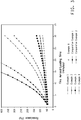
- Figures 1 and 2 show the effect of varying the pore size of the nanoweb layer on the pressure drop increase over 0.5 hours across the web.
- pressure drop increase is plotted against the mean flow pore size ratio between the upstream media and the nanoweb.
- the pressure drop increase is plotted against upstream media absolute pore size in microns.
- the pressure drop has a desirable minimum.
- the position of the minimum shifts to higher ratio as the nanoweb pore size increases, i.e. the efficiency rating of the nanoweb increases.
- Figures 3 illustrates the increase in pressure drop of the examples and comparative examples as a function of filtering time.
Claims (15)
- Milieu filtrant comprenant un voile de nanofibres présentant un diamètre de fibre moyen en nombre inférieur à un micron et une couche de voile de microfibres en amont dans une relation face à face avec le voile de nanofibres où le rapport de la taille des pores à écoulement moyen de la couche de voile de microfibres à celle du voile de nanofibres est compris entre 1 à 10 et la taille des pores à écoulement moyen de la couche de voile de microfibres est comprise entre 12 à 40 microns.
- Milieu selon la revendication 1 dans lequel le nanovoile présente un poids de base d'au moins 2 g/m2.
- Milieu selon la revendication 2 dans lequel le nanovoile présente un poids de base d'au moins 3 g/m2.
- Milieu selon la revendication 1 dans lequel la couche en amont comprend un voile polymère soufflé à l'état fondu.
- Milieu selon la revendication 1 dans lequel le voile de nanofibres comprend un voile non-tissé fabriqué selon un procédé sélectionné dans le groupe constitué de l'électrosoufflage, de l'électrofilage, du filage centrifuge et du soufflage à l'état fondu.
- Milieu selon la revendication 1 qui comprend en outre une couche de support de renfort tissé en contact avec soit le voile de nanofibres soit la couche en amont soit les deux.
- Milieu selon la revendication 1 dans lequel un renfort tissé est positionné entre le voile de nanofibres et la couche non-tissée en amont.
- Milieu selon la revendication 1 dans lequel le poids de base de la couche en amont est supérieur à 10 g/m2.
- Procédé de filtration d'air comprenant l'étape de passage de l'air à travers un milieu comprenant un voile de nanofibres présentant un diamètre de fibre moyen en nombre inférieur à un micron et une couche de voile de microfibres en amont dans une relation face à face avec le voile de nanofibres où le rapport de la taille des pores à écoulement moyen de la couche de voile de microfibres à celle du voile de nanofibres est compris entre 1 à 10 et la taille des pores à écoulement moyen de la couche de voile de microfibres est comprise entre 12 à 40 microns.
- Procédé selon la revendication 9 dans lequel le nanovoile présente un poids de base d'au moins 2 g/m2, préférablement d'au moins 3 g/m2.
- Procédé selon la revendication 9 dans lequel un renfort tissé est positionné entre le voile de nanofibres et la couche non-tissée en amont.
- Procédé selon la revendication 9 dans lequel le poids de base de la couche en amont est supérieur à 10 g/m2.
- Procédé selon la revendication 9 dans lequel la couche en amont comprend un voile polymère soufflé à l'état fondu.
- Procédé selon la revendication 9 dans lequel le voile de nanofibres comprend un voile non-tissé fabriqué selon un procédé sélectionné dans le groupe constitué de l'électrosoufflage, de l'électrofilage, du filage centrifuge et du soufflage à l'état fondu.
- Procédé selon la revendication 9 qui comprend en outre une couche de support de renfort tissé en contact avec soit le voile de nanofibres soit la couche en amont soit les deux.
Applications Claiming Priority (3)
| Application Number | Priority Date | Filing Date | Title |
|---|---|---|---|
| US12335008P | 2008-04-07 | 2008-04-07 | |
| US13249808P | 2008-06-19 | 2008-06-19 | |
| PCT/US2009/039742 WO2009126605A2 (fr) | 2008-04-07 | 2009-04-07 | Milieu de filtration de l'air, présentant une capacité améliorée de dépoussiérage et une résistance améliorée à un environnement présentant une grande humidité |
Publications (2)
| Publication Number | Publication Date |
|---|---|
| EP2259860A2 EP2259860A2 (fr) | 2010-12-15 |
| EP2259860B1 true EP2259860B1 (fr) | 2018-10-31 |
Family
ID=41100566
Family Applications (1)
| Application Number | Title | Priority Date | Filing Date |
|---|---|---|---|
| EP09729386.4A Active EP2259860B1 (fr) | 2008-04-07 | 2009-04-07 | Milieu de filtration de l'air, présentant une capacité améliorée de dépoussiérage et une résistance améliorée à un environnement présentant une grande humidité |
Country Status (7)
| Country | Link |
|---|---|
| US (1) | US8282712B2 (fr) |
| EP (1) | EP2259860B1 (fr) |
| JP (1) | JP5619723B2 (fr) |
| KR (1) | KR101700455B1 (fr) |
| CN (1) | CN101983097B (fr) |
| BR (1) | BRPI0906535A2 (fr) |
| WO (1) | WO2009126605A2 (fr) |
Families Citing this family (45)
| Publication number | Priority date | Publication date | Assignee | Title |
|---|---|---|---|---|
| US6743273B2 (en) | 2000-09-05 | 2004-06-01 | Donaldson Company, Inc. | Polymer, polymer microfiber, polymer nanofiber and applications including filter structures |
| US8513147B2 (en) | 2003-06-19 | 2013-08-20 | Eastman Chemical Company | Nonwovens produced from multicomponent fibers |
| US20040260034A1 (en) | 2003-06-19 | 2004-12-23 | Haile William Alston | Water-dispersible fibers and fibrous articles |
| US7892993B2 (en) | 2003-06-19 | 2011-02-22 | Eastman Chemical Company | Water-dispersible and multicomponent fibers from sulfopolyesters |
| US8172092B2 (en) * | 2009-01-22 | 2012-05-08 | Clarcor Inc. | Filter having melt-blown and electrospun fibers |
| WO2010096398A1 (fr) * | 2009-02-17 | 2010-08-26 | Filtrona Richmond, Inc. | Structures de fibres transmissives des fluides et multicouches contenant des nanofibres et procédé de fabrication de telles structures |
| SG10201801667YA (en) | 2009-03-19 | 2018-03-28 | Emd Millipore Corp | Removal of microorganisms from fluid samples using nanofiber filtration media |
| US8512519B2 (en) | 2009-04-24 | 2013-08-20 | Eastman Chemical Company | Sulfopolyesters for paper strength and process |
| US8636833B2 (en) * | 2009-09-16 | 2014-01-28 | E I Du Pont De Nemours And Company | Air filtration medium with improved dust loading capacity and improved resistance to high humidity environment |
| ES2774949T3 (es) | 2010-08-10 | 2020-07-23 | Emd Millipore Corp | Método para la eliminación de retrovirus |
| US9273417B2 (en) | 2010-10-21 | 2016-03-01 | Eastman Chemical Company | Wet-Laid process to produce a bound nonwoven article |
| KR101551298B1 (ko) | 2011-04-01 | 2015-09-08 | 이엠디 밀리포어 코포레이션 | 나노섬유 함유 복합재료 구조 |
| CN102240490A (zh) * | 2011-07-13 | 2011-11-16 | 东华大学 | 一种暖通空调用折叠式空气净化过滤器 |
| KR102178689B1 (ko) * | 2011-08-12 | 2020-11-13 | 도널드선 컴파니 인코포레이티드 | 멜트-블로운 섬유를 포함하는 액체 여과 매질 |
| JP5838408B2 (ja) | 2011-10-27 | 2016-01-06 | 株式会社生方製作所 | 静電容量式液面センサー |
| US9050546B2 (en) | 2012-01-05 | 2015-06-09 | Tdc Filter Manufacturing, Inc. | Waterproof and salt repellant media and filter |
| US8871052B2 (en) | 2012-01-31 | 2014-10-28 | Eastman Chemical Company | Processes to produce short cut microfibers |
| JP2014084548A (ja) * | 2012-10-26 | 2014-05-12 | Teijin Ltd | 不織布およびその製造方法 |
| US20140190137A1 (en) * | 2013-01-10 | 2014-07-10 | Tdc Filter Manufacturing, Inc. | Media and Filter for Coastal and High Humidity Areas |
| MX346385B (es) | 2013-02-14 | 2017-03-16 | Nanopareil Llc | Fieltros hibridos de nanofibras electrohiladas. |
| AU2014237819B2 (en) | 2013-03-15 | 2018-12-06 | Donaldson Company, Inc. | Filter media and elements |
| US9303357B2 (en) | 2013-04-19 | 2016-04-05 | Eastman Chemical Company | Paper and nonwoven articles comprising synthetic microfiber binders |
| DE102013007118A1 (de) * | 2013-04-25 | 2014-10-30 | Mann + Hummel Gmbh | Mehrlagiges Filterelement |
| US9474994B2 (en) | 2013-06-17 | 2016-10-25 | Donaldson Company, Inc. | Filter media and elements |
| EP3060326B1 (fr) | 2013-10-21 | 2017-11-22 | E. I. du Pont de Nemours and Company | Bande nanofibreuse d'électret utilisée comme matériau de filtration de l'air |
| JP6158061B2 (ja) * | 2013-12-10 | 2017-07-05 | 北越紀州製紙株式会社 | エアフィルタ用濾材 |
| US9605126B2 (en) | 2013-12-17 | 2017-03-28 | Eastman Chemical Company | Ultrafiltration process for the recovery of concentrated sulfopolyester dispersion |
| US9598802B2 (en) | 2013-12-17 | 2017-03-21 | Eastman Chemical Company | Ultrafiltration process for producing a sulfopolyester concentrate |
| US10343095B2 (en) * | 2014-12-19 | 2019-07-09 | Hollingsworth & Vose Company | Filter media comprising a pre-filter layer |
| US10632411B2 (en) | 2015-03-25 | 2020-04-28 | K&N Engineering, Inc. | HVAC home air filter |
| US11241647B2 (en) | 2015-03-25 | 2022-02-08 | K&N Engineering, Inc. | HVAC home air filter |
| US10828587B2 (en) * | 2015-04-17 | 2020-11-10 | Hollingsworth & Vose Company | Stable filter media including nanofibers |
| WO2016167871A1 (fr) | 2015-04-17 | 2016-10-20 | Emd Millipore Corporation | Procédé de purification d'une matière biologique d'intérêt dans un échantillon au moyen de membranes d'ultrafiltration à nanofibres mises en oeuvre en mode de filtration de flux tangentiel |
| US10449474B2 (en) | 2015-09-18 | 2019-10-22 | Hollingsworth & Vose Company | Filter media including a waved filtration layer |
| US10561972B2 (en) * | 2015-09-18 | 2020-02-18 | Hollingsworth & Vose Company | Filter media including a waved filtration layer |
| CA3030560A1 (fr) * | 2016-07-11 | 2018-01-18 | K&N Engineering, Inc. | Filtre a air domestique (hvac) |
| WO2018175556A1 (fr) * | 2017-03-22 | 2018-09-27 | Hollingsworth & Vose Company | Matériaux filtrants comprenant une couche de filtration ondulée |
| US11547963B2 (en) | 2017-03-29 | 2023-01-10 | Knowlton Technologies, Llc | High efficiency synthetic filter media |
| US20180290087A1 (en) * | 2017-04-11 | 2018-10-11 | Hollingsworth & Vose Company | Polyethersulfone fiber webs |
| MX2020013310A (es) | 2018-06-08 | 2021-05-27 | Ascend Performance Mat Operations Llc | Productos no tejidos de nanofibras afinables. |
| US11420143B2 (en) | 2018-11-05 | 2022-08-23 | Hollingsworth & Vose Company | Filter media with irregular structure and/or reversibly stretchable layers |
| US11433332B2 (en) | 2018-11-05 | 2022-09-06 | Hollingsworth & Vose Company | Filter media with irregular structure |
| US11452959B2 (en) | 2018-11-30 | 2022-09-27 | Hollingsworth & Vose Company | Filter media having a fine pore size distribution |
| EP3953169B1 (fr) | 2019-04-12 | 2023-12-20 | Ascend Performance Materials Operations LLC | Structures multicouches non tissées ayant des couches de nanofibres |
| KR102127319B1 (ko) * | 2019-07-09 | 2020-06-29 | 주식회사 대창 | 나노섬유를 포함하는 기재 및 이를 제조하는 방법 |
Family Cites Families (41)
| Publication number | Priority date | Publication date | Assignee | Title |
|---|---|---|---|---|
| US2797163A (en) | 1952-11-22 | 1957-06-25 | Walter J Smith | Method of making filter media |
| US3253978A (en) | 1961-07-19 | 1966-05-31 | C H Dexter & Sons Inc | Method of forming an inorganic waterlaid sheet containing colloidal silica and cationic starch |
| US3228825A (en) | 1961-08-15 | 1966-01-11 | Owens Corning Fiberglass Corp | Method of forming fibrous structures from a combination of glass fibers and cellulosic fibers |
| NL292776A (fr) | 1962-10-01 | |||
| DE1494897B2 (de) | 1963-05-29 | 1971-11-11 | J P Stevens & Co Ine , New York, N Y (V St A) | Verfahren zum reinigen von schlichte aufweisendem glasfaser material |
| US3249491A (en) | 1963-07-15 | 1966-05-03 | James A Young | Process for molding a glass fiber aerosol filter |
| US3882135A (en) | 1972-08-31 | 1975-05-06 | Dow Chemical Co | Process for the preparation of aminopyridines |
| GB1522605A (en) | 1974-09-26 | 1978-08-23 | Ici Ltd | Preparation of fibrous sheet product |
| NL181632C (nl) | 1976-12-23 | 1987-10-01 | Minnesota Mining & Mfg | Electreetfilter en werkwijze voor het vervaardigen daarvan. |
| US4536361A (en) | 1978-08-28 | 1985-08-20 | Torobin Leonard B | Method for producing plastic microfilaments |
| US4874659A (en) | 1984-10-24 | 1989-10-17 | Toray Industries | Electret fiber sheet and method of producing same |
| DE9320208U1 (de) | 1993-12-31 | 1994-03-31 | Kalthoff Luftfilter Und Filter | Mehrschichtiges Filtermaterial |
| DE4443158A1 (de) | 1994-12-05 | 1996-06-13 | Gessner & Co Gmbh | Abreinigbares Filtermedium |
| US6171684B1 (en) | 1995-11-17 | 2001-01-09 | Donaldson Company, Inc. | Filter material construction and method |
| US5672399A (en) | 1995-11-17 | 1997-09-30 | Donaldson Company, Inc. | Filter material construction and method |
| DE19618758C2 (de) | 1996-05-09 | 2001-08-23 | Fibermark Gessner Gmbh & Co | Ein- oder mehrlagiges, abreinigbares Filtermedium und Filterelement |
| US6183670B1 (en) | 1997-09-23 | 2001-02-06 | Leonard Torobin | Method and apparatus for producing high efficiency fibrous media incorporating discontinuous sub-micron diameter fibers, and web media formed thereby |
| US6315806B1 (en) | 1997-09-23 | 2001-11-13 | Leonard Torobin | Method and apparatus for producing high efficiency fibrous media incorporating discontinuous sub-micron diameter fibers, and web media formed thereby |
| JP2001518378A (ja) * | 1997-09-29 | 2001-10-16 | ドナルドソン カンパニー,インコーポレイティド | フィルタ構造および方法 |
| CN1134280C (zh) * | 1997-09-29 | 2004-01-14 | 唐纳森公司 | 过滤器材料的结构及其制作方法 |
| WO2000022207A2 (fr) | 1998-10-01 | 2000-04-20 | The University Of Akron | Procede et appareil permettant de produire des nanofibres |
| DE19920983C5 (de) | 1999-05-06 | 2004-11-18 | Fibermark Gessner Gmbh & Co. Ohg | Zwei- oder mehrlagiges Filtermedium für die Luftfiltration und daraus hergestelltes Filterelement |
| ES2223560T3 (es) * | 1999-08-02 | 2005-03-01 | E.I. Du Pont De Nemours And Company | Material laminar compuesto no tejido. |
| JP2002001027A (ja) * | 2000-06-22 | 2002-01-08 | Tennex Corp | 多層集塵フィルター |
| GB0113776D0 (en) * | 2001-06-06 | 2001-07-25 | Switched Reluctance Drives Ltd | Excitation of switched reluctance motors |
| US6520425B1 (en) | 2001-08-21 | 2003-02-18 | The University Of Akron | Process and apparatus for the production of nanofibers |
| US6695992B2 (en) | 2002-01-22 | 2004-02-24 | The University Of Akron | Process and apparatus for the production of nanofibers |
| KR100549140B1 (ko) | 2002-03-26 | 2006-02-03 | 이 아이 듀폰 디 네모아 앤드 캄파니 | 일렉트로-브로운 방사법에 의한 초극세 나노섬유 웹제조방법 |
| EP1540062B1 (fr) * | 2002-09-17 | 2009-11-04 | E.I. Du Pont De Nemours And Company | Tissus ayant d'extremement hautes proprietes barrieres au liquide |
| US7125434B2 (en) | 2002-12-19 | 2006-10-24 | Millipore Corporation | Deep gradient-density filter device |
| US7008465B2 (en) | 2003-06-19 | 2006-03-07 | Donaldson Company, Inc. | Cleanable high efficiency filter media structure and applications for use |
| CN100484607C (zh) * | 2003-06-19 | 2009-05-06 | 唐纳森公司 | 可清洁的高效过滤介质结构及其应用 |
| JP4614669B2 (ja) * | 2004-02-03 | 2011-01-19 | 日本バイリーン株式会社 | 濾過材及びフィルタ |
| DE602005024259D1 (de) | 2004-04-19 | 2010-12-02 | Procter & Gamble | Fasern, vliesstoffe und erzeugnisse mit nanofasern aus polymeren mit einer hohen glasübergangstemperatur |
| US7591883B2 (en) | 2004-09-27 | 2009-09-22 | Cornell Research Foundation, Inc. | Microfiber supported nanofiber membrane |
| US8092566B2 (en) | 2004-12-28 | 2012-01-10 | E.I. Du Pont De Nemours And Company | Filtration media for filtering particulate material from gas streams |
| JP4657782B2 (ja) * | 2005-04-07 | 2011-03-23 | 帝人テクノプロダクツ株式会社 | 高捕集効率と低圧力損失とを兼ね備えたフィルター |
| JP4745815B2 (ja) * | 2005-12-20 | 2011-08-10 | 帝人テクノプロダクツ株式会社 | 内燃機関空気取り入れ用フィルター材 |
| EP1834683A1 (fr) | 2006-03-14 | 2007-09-19 | Diolen Industrial Fibers B.V. | Tissu de support et élément filtrant le comprenant |
| JP2007301436A (ja) * | 2006-05-08 | 2007-11-22 | Kanai Juyo Kogyo Co Ltd | エアフィルタ用濾材 |
| WO2008032388A1 (fr) * | 2006-09-14 | 2008-03-20 | Dynic Corporation | Matériau de filtre à air |
-
2009
- 2009-04-06 US US12/418,928 patent/US8282712B2/en active Active
- 2009-04-07 EP EP09729386.4A patent/EP2259860B1/fr active Active
- 2009-04-07 KR KR1020107024866A patent/KR101700455B1/ko active IP Right Grant
- 2009-04-07 WO PCT/US2009/039742 patent/WO2009126605A2/fr active Application Filing
- 2009-04-07 BR BRPI0906535-0A patent/BRPI0906535A2/pt not_active IP Right Cessation
- 2009-04-07 CN CN200980111858.2A patent/CN101983097B/zh active Active
- 2009-04-07 JP JP2011504120A patent/JP5619723B2/ja active Active
Non-Patent Citations (1)
| Title |
|---|
| None * |
Also Published As
| Publication number | Publication date |
|---|---|
| US20090249956A1 (en) | 2009-10-08 |
| KR101700455B1 (ko) | 2017-02-13 |
| BRPI0906535A2 (pt) | 2015-06-30 |
| WO2009126605A2 (fr) | 2009-10-15 |
| JP5619723B2 (ja) | 2014-11-05 |
| JP2011516261A (ja) | 2011-05-26 |
| US8282712B2 (en) | 2012-10-09 |
| CN101983097B (zh) | 2014-08-27 |
| KR20110004424A (ko) | 2011-01-13 |
| EP2259860A2 (fr) | 2010-12-15 |
| WO2009126605A3 (fr) | 2010-03-25 |
| CN101983097A (zh) | 2011-03-02 |
Similar Documents
| Publication | Publication Date | Title |
|---|---|---|
| EP2259860B1 (fr) | Milieu de filtration de l'air, présentant une capacité améliorée de dépoussiérage et une résistance améliorée à un environnement présentant une grande humidité | |
| EP2477712B1 (fr) | Matériau de filtration de l'air présentant une capacité d'empoussiérage accrue et une résistance à un environnement très humide améliorée | |
| US20200215471A1 (en) | Filter media including oriented fibers | |
| EP2142275B1 (fr) | Dépoussiéreurs à sacs filtrants | |
| JP5539877B2 (ja) | 改良されたプリーツ付きナノウェブ構造体 | |
| US8721756B2 (en) | Filter construction for use with air in-take for gas turbine and methods | |
| EP1276548B1 (fr) | Milieu filtrant | |
| KR102156278B1 (ko) | 나노웨브 층을 가진 필터 매체 | |
| CN109562311B (zh) | 过滤介质、过滤元件和过滤方法 | |
| CN108778452B (zh) | 包括包含合成纤维的过滤层的过滤介质 | |
| JP2015077599A (ja) | ナノウェブとスクリムの耐久性積層物 | |
| KR20070115873A (ko) | 기체 스트림으로부터 미립자 물질을 여과하기 위한 여과매질 | |
| TWI758722B (zh) | 包含聚醯胺奈米纖維層的過濾器介質 |
Legal Events
| Date | Code | Title | Description |
|---|---|---|---|
| PUAI | Public reference made under article 153(3) epc to a published international application that has entered the european phase |
Free format text: ORIGINAL CODE: 0009012 |
|
| 17P | Request for examination filed |
Effective date: 20100831 |
|
| AK | Designated contracting states |
Kind code of ref document: A2 Designated state(s): AT BE BG CH CY CZ DE DK EE ES FI FR GB GR HR HU IE IS IT LI LT LU LV MC MK MT NL NO PL PT RO SE SI SK TR |
|
| AX | Request for extension of the european patent |
Extension state: AL BA RS |
|
| DAX | Request for extension of the european patent (deleted) | ||
| STAA | Information on the status of an ep patent application or granted ep patent |
Free format text: STATUS: EXAMINATION IS IN PROGRESS |
|
| 17Q | First examination report despatched |
Effective date: 20170927 |
|
| GRAP | Despatch of communication of intention to grant a patent |
Free format text: ORIGINAL CODE: EPIDOSNIGR1 |
|
| STAA | Information on the status of an ep patent application or granted ep patent |
Free format text: STATUS: GRANT OF PATENT IS INTENDED |
|
| INTG | Intention to grant announced |
Effective date: 20180618 |
|
| GRAS | Grant fee paid |
Free format text: ORIGINAL CODE: EPIDOSNIGR3 |
|
| GRAA | (expected) grant |
Free format text: ORIGINAL CODE: 0009210 |
|
| STAA | Information on the status of an ep patent application or granted ep patent |
Free format text: STATUS: THE PATENT HAS BEEN GRANTED |
|
| AK | Designated contracting states |
Kind code of ref document: B1 Designated state(s): AT BE BG CH CY CZ DE DK EE ES FI FR GB GR HR HU IE IS IT LI LT LU LV MC MK MT NL NO PL PT RO SE SI SK TR |
|
| REG | Reference to a national code |
Ref country code: CH Ref legal event code: EP Ref country code: GB Ref legal event code: FG4D |
|
| REG | Reference to a national code |
Ref country code: AT Ref legal event code: REF Ref document number: 1058709 Country of ref document: AT Kind code of ref document: T Effective date: 20181115 |
|
| REG | Reference to a national code |
Ref country code: IE Ref legal event code: FG4D |
|
| REG | Reference to a national code |
Ref country code: DE Ref legal event code: R096 Ref document number: 602009055367 Country of ref document: DE |
|
| REG | Reference to a national code |
Ref country code: NL Ref legal event code: MP Effective date: 20181031 |
|
| REG | Reference to a national code |
Ref country code: LT Ref legal event code: MG4D |
|
| REG | Reference to a national code |
Ref country code: AT Ref legal event code: MK05 Ref document number: 1058709 Country of ref document: AT Kind code of ref document: T Effective date: 20181031 |
|
| PG25 | Lapsed in a contracting state [announced via postgrant information from national office to epo] |
Ref country code: LV Free format text: LAPSE BECAUSE OF FAILURE TO SUBMIT A TRANSLATION OF THE DESCRIPTION OR TO PAY THE FEE WITHIN THE PRESCRIBED TIME-LIMIT Effective date: 20181031 Ref country code: AT Free format text: LAPSE BECAUSE OF FAILURE TO SUBMIT A TRANSLATION OF THE DESCRIPTION OR TO PAY THE FEE WITHIN THE PRESCRIBED TIME-LIMIT Effective date: 20181031 Ref country code: IS Free format text: LAPSE BECAUSE OF FAILURE TO SUBMIT A TRANSLATION OF THE DESCRIPTION OR TO PAY THE FEE WITHIN THE PRESCRIBED TIME-LIMIT Effective date: 20190228 Ref country code: ES Free format text: LAPSE BECAUSE OF FAILURE TO SUBMIT A TRANSLATION OF THE DESCRIPTION OR TO PAY THE FEE WITHIN THE PRESCRIBED TIME-LIMIT Effective date: 20181031 Ref country code: NO Free format text: LAPSE BECAUSE OF FAILURE TO SUBMIT A TRANSLATION OF THE DESCRIPTION OR TO PAY THE FEE WITHIN THE PRESCRIBED TIME-LIMIT Effective date: 20190131 Ref country code: LT Free format text: LAPSE BECAUSE OF FAILURE TO SUBMIT A TRANSLATION OF THE DESCRIPTION OR TO PAY THE FEE WITHIN THE PRESCRIBED TIME-LIMIT Effective date: 20181031 Ref country code: FI Free format text: LAPSE BECAUSE OF FAILURE TO SUBMIT A TRANSLATION OF THE DESCRIPTION OR TO PAY THE FEE WITHIN THE PRESCRIBED TIME-LIMIT Effective date: 20181031 Ref country code: BG Free format text: LAPSE BECAUSE OF FAILURE TO SUBMIT A TRANSLATION OF THE DESCRIPTION OR TO PAY THE FEE WITHIN THE PRESCRIBED TIME-LIMIT Effective date: 20190131 Ref country code: HR Free format text: LAPSE BECAUSE OF FAILURE TO SUBMIT A TRANSLATION OF THE DESCRIPTION OR TO PAY THE FEE WITHIN THE PRESCRIBED TIME-LIMIT Effective date: 20181031 Ref country code: PL Free format text: LAPSE BECAUSE OF FAILURE TO SUBMIT A TRANSLATION OF THE DESCRIPTION OR TO PAY THE FEE WITHIN THE PRESCRIBED TIME-LIMIT Effective date: 20181031 |
|
| PG25 | Lapsed in a contracting state [announced via postgrant information from national office to epo] |
Ref country code: SE Free format text: LAPSE BECAUSE OF FAILURE TO SUBMIT A TRANSLATION OF THE DESCRIPTION OR TO PAY THE FEE WITHIN THE PRESCRIBED TIME-LIMIT Effective date: 20181031 Ref country code: GR Free format text: LAPSE BECAUSE OF FAILURE TO SUBMIT A TRANSLATION OF THE DESCRIPTION OR TO PAY THE FEE WITHIN THE PRESCRIBED TIME-LIMIT Effective date: 20190201 Ref country code: NL Free format text: LAPSE BECAUSE OF FAILURE TO SUBMIT A TRANSLATION OF THE DESCRIPTION OR TO PAY THE FEE WITHIN THE PRESCRIBED TIME-LIMIT Effective date: 20181031 Ref country code: PT Free format text: LAPSE BECAUSE OF FAILURE TO SUBMIT A TRANSLATION OF THE DESCRIPTION OR TO PAY THE FEE WITHIN THE PRESCRIBED TIME-LIMIT Effective date: 20190301 |
|
| PG25 | Lapsed in a contracting state [announced via postgrant information from national office to epo] |
Ref country code: DK Free format text: LAPSE BECAUSE OF FAILURE TO SUBMIT A TRANSLATION OF THE DESCRIPTION OR TO PAY THE FEE WITHIN THE PRESCRIBED TIME-LIMIT Effective date: 20181031 Ref country code: IT Free format text: LAPSE BECAUSE OF FAILURE TO SUBMIT A TRANSLATION OF THE DESCRIPTION OR TO PAY THE FEE WITHIN THE PRESCRIBED TIME-LIMIT Effective date: 20181031 Ref country code: CZ Free format text: LAPSE BECAUSE OF FAILURE TO SUBMIT A TRANSLATION OF THE DESCRIPTION OR TO PAY THE FEE WITHIN THE PRESCRIBED TIME-LIMIT Effective date: 20181031 |
|
| REG | Reference to a national code |
Ref country code: DE Ref legal event code: R097 Ref document number: 602009055367 Country of ref document: DE |
|
| PG25 | Lapsed in a contracting state [announced via postgrant information from national office to epo] |
Ref country code: RO Free format text: LAPSE BECAUSE OF FAILURE TO SUBMIT A TRANSLATION OF THE DESCRIPTION OR TO PAY THE FEE WITHIN THE PRESCRIBED TIME-LIMIT Effective date: 20181031 Ref country code: EE Free format text: LAPSE BECAUSE OF FAILURE TO SUBMIT A TRANSLATION OF THE DESCRIPTION OR TO PAY THE FEE WITHIN THE PRESCRIBED TIME-LIMIT Effective date: 20181031 Ref country code: SK Free format text: LAPSE BECAUSE OF FAILURE TO SUBMIT A TRANSLATION OF THE DESCRIPTION OR TO PAY THE FEE WITHIN THE PRESCRIBED TIME-LIMIT Effective date: 20181031 |
|
| PLBE | No opposition filed within time limit |
Free format text: ORIGINAL CODE: 0009261 |
|
| STAA | Information on the status of an ep patent application or granted ep patent |
Free format text: STATUS: NO OPPOSITION FILED WITHIN TIME LIMIT |
|
| 26N | No opposition filed |
Effective date: 20190801 |
|
| PG25 | Lapsed in a contracting state [announced via postgrant information from national office to epo] |
Ref country code: SI Free format text: LAPSE BECAUSE OF FAILURE TO SUBMIT A TRANSLATION OF THE DESCRIPTION OR TO PAY THE FEE WITHIN THE PRESCRIBED TIME-LIMIT Effective date: 20181031 |
|
| REG | Reference to a national code |
Ref country code: CH Ref legal event code: PL |
|
| REG | Reference to a national code |
Ref country code: BE Ref legal event code: MM Effective date: 20190430 |
|
| PG25 | Lapsed in a contracting state [announced via postgrant information from national office to epo] |
Ref country code: LU Free format text: LAPSE BECAUSE OF NON-PAYMENT OF DUE FEES Effective date: 20190407 Ref country code: MC Free format text: LAPSE BECAUSE OF FAILURE TO SUBMIT A TRANSLATION OF THE DESCRIPTION OR TO PAY THE FEE WITHIN THE PRESCRIBED TIME-LIMIT Effective date: 20181031 |
|
| PG25 | Lapsed in a contracting state [announced via postgrant information from national office to epo] |
Ref country code: CH Free format text: LAPSE BECAUSE OF NON-PAYMENT OF DUE FEES Effective date: 20190430 Ref country code: LI Free format text: LAPSE BECAUSE OF NON-PAYMENT OF DUE FEES Effective date: 20190430 |
|
| PG25 | Lapsed in a contracting state [announced via postgrant information from national office to epo] |
Ref country code: BE Free format text: LAPSE BECAUSE OF NON-PAYMENT OF DUE FEES Effective date: 20190430 |
|
| PG25 | Lapsed in a contracting state [announced via postgrant information from national office to epo] |
Ref country code: TR Free format text: LAPSE BECAUSE OF FAILURE TO SUBMIT A TRANSLATION OF THE DESCRIPTION OR TO PAY THE FEE WITHIN THE PRESCRIBED TIME-LIMIT Effective date: 20181031 |
|
| PG25 | Lapsed in a contracting state [announced via postgrant information from national office to epo] |
Ref country code: IE Free format text: LAPSE BECAUSE OF NON-PAYMENT OF DUE FEES Effective date: 20190407 |
|
| PG25 | Lapsed in a contracting state [announced via postgrant information from national office to epo] |
Ref country code: CY Free format text: LAPSE BECAUSE OF FAILURE TO SUBMIT A TRANSLATION OF THE DESCRIPTION OR TO PAY THE FEE WITHIN THE PRESCRIBED TIME-LIMIT Effective date: 20181031 |
|
| PG25 | Lapsed in a contracting state [announced via postgrant information from national office to epo] |
Ref country code: HU Free format text: LAPSE BECAUSE OF FAILURE TO SUBMIT A TRANSLATION OF THE DESCRIPTION OR TO PAY THE FEE WITHIN THE PRESCRIBED TIME-LIMIT; INVALID AB INITIO Effective date: 20090407 Ref country code: MT Free format text: LAPSE BECAUSE OF FAILURE TO SUBMIT A TRANSLATION OF THE DESCRIPTION OR TO PAY THE FEE WITHIN THE PRESCRIBED TIME-LIMIT Effective date: 20181031 |
|
| PG25 | Lapsed in a contracting state [announced via postgrant information from national office to epo] |
Ref country code: MK Free format text: LAPSE BECAUSE OF FAILURE TO SUBMIT A TRANSLATION OF THE DESCRIPTION OR TO PAY THE FEE WITHIN THE PRESCRIBED TIME-LIMIT Effective date: 20181031 |
|
| REG | Reference to a national code |
Ref country code: DE Ref legal event code: R081 Ref document number: 602009055367 Country of ref document: DE Owner name: DUPONT SAFETY & CONSTRUCTION, INC., WILMINGTON, US Free format text: FORMER OWNER: E.I. DU PONT DE NEMOURS AND COMPANY, WILMINGTON, DEL., US |
|
| REG | Reference to a national code |
Ref country code: GB Ref legal event code: 732E Free format text: REGISTERED BETWEEN 20221027 AND 20221102 |
|
| PGFP | Annual fee paid to national office [announced via postgrant information from national office to epo] |
Ref country code: FR Payment date: 20230309 Year of fee payment: 15 |
|
| PGFP | Annual fee paid to national office [announced via postgrant information from national office to epo] |
Ref country code: GB Payment date: 20230302 Year of fee payment: 15 |
|
| P01 | Opt-out of the competence of the unified patent court (upc) registered |
Effective date: 20230528 |
|
| PGFP | Annual fee paid to national office [announced via postgrant information from national office to epo] |
Ref country code: DE Payment date: 20230307 Year of fee payment: 15 |