EP2256255B1 - Dispositif pour placer des câbles - Google Patents
Dispositif pour placer des câbles Download PDFInfo
- Publication number
- EP2256255B1 EP2256255B1 EP10164163.7A EP10164163A EP2256255B1 EP 2256255 B1 EP2256255 B1 EP 2256255B1 EP 10164163 A EP10164163 A EP 10164163A EP 2256255 B1 EP2256255 B1 EP 2256255B1
- Authority
- EP
- European Patent Office
- Prior art keywords
- laying
- cutting
- cutting device
- media lines
- laying device
- Prior art date
- Legal status (The legal status is an assumption and is not a legal conclusion. Google has not performed a legal analysis and makes no representation as to the accuracy of the status listed.)
- Active
Links
- 239000002689 soil Substances 0.000 claims description 26
- 238000000034 method Methods 0.000 claims description 11
- 230000010355 oscillation Effects 0.000 claims 1
- 238000007599 discharging Methods 0.000 description 13
- 238000001514 detection method Methods 0.000 description 5
- 238000010276 construction Methods 0.000 description 3
- 238000013461 design Methods 0.000 description 3
- 230000035515 penetration Effects 0.000 description 3
- 238000004873 anchoring Methods 0.000 description 2
- 238000005452 bending Methods 0.000 description 2
- 238000012937 correction Methods 0.000 description 2
- 238000009434 installation Methods 0.000 description 2
- 238000013138 pruning Methods 0.000 description 2
- 230000015572 biosynthetic process Effects 0.000 description 1
- 239000003638 chemical reducing agent Substances 0.000 description 1
- 230000006378 damage Effects 0.000 description 1
- 230000001419 dependent effect Effects 0.000 description 1
- 239000000839 emulsion Substances 0.000 description 1
- ZINJLDJMHCUBIP-UHFFFAOYSA-N ethametsulfuron-methyl Chemical compound CCOC1=NC(NC)=NC(NC(=O)NS(=O)(=O)C=2C(=CC=CC=2)C(=O)OC)=N1 ZINJLDJMHCUBIP-UHFFFAOYSA-N 0.000 description 1
- 238000011156 evaluation Methods 0.000 description 1
- 239000011888 foil Substances 0.000 description 1
- 239000002655 kraft paper Substances 0.000 description 1
- 239000000463 material Substances 0.000 description 1
- 230000000149 penetrating effect Effects 0.000 description 1
- 239000004576 sand Substances 0.000 description 1
- 238000012549 training Methods 0.000 description 1
- XLYOFNOQVPJJNP-UHFFFAOYSA-N water Substances O XLYOFNOQVPJJNP-UHFFFAOYSA-N 0.000 description 1
Images


Classifications
-
- H—ELECTRICITY
- H02—GENERATION; CONVERSION OR DISTRIBUTION OF ELECTRIC POWER
- H02G—INSTALLATION OF ELECTRIC CABLES OR LINES, OR OF COMBINED OPTICAL AND ELECTRIC CABLES OR LINES
- H02G1/00—Methods or apparatus specially adapted for installing, maintaining, repairing or dismantling electric cables or lines
- H02G1/06—Methods or apparatus specially adapted for installing, maintaining, repairing or dismantling electric cables or lines for laying cables, e.g. laying apparatus on vehicle
-
- E—FIXED CONSTRUCTIONS
- E02—HYDRAULIC ENGINEERING; FOUNDATIONS; SOIL SHIFTING
- E02F—DREDGING; SOIL-SHIFTING
- E02F5/00—Dredgers or soil-shifting machines for special purposes
- E02F5/02—Dredgers or soil-shifting machines for special purposes for digging trenches or ditches
- E02F5/10—Dredgers or soil-shifting machines for special purposes for digging trenches or ditches with arrangements for reinforcing trenches or ditches; with arrangements for making or assembling conduits or for laying conduits or cables
- E02F5/101—Dredgers or soil-shifting machines for special purposes for digging trenches or ditches with arrangements for reinforcing trenches or ditches; with arrangements for making or assembling conduits or for laying conduits or cables forming during digging, e.g. underground canalisations or conduits, by bending or twisting a strip of pliable material; by extrusion
-
- E—FIXED CONSTRUCTIONS
- E02—HYDRAULIC ENGINEERING; FOUNDATIONS; SOIL SHIFTING
- E02F—DREDGING; SOIL-SHIFTING
- E02F5/00—Dredgers or soil-shifting machines for special purposes
- E02F5/02—Dredgers or soil-shifting machines for special purposes for digging trenches or ditches
- E02F5/10—Dredgers or soil-shifting machines for special purposes for digging trenches or ditches with arrangements for reinforcing trenches or ditches; with arrangements for making or assembling conduits or for laying conduits or cables
- E02F5/102—Dredgers or soil-shifting machines for special purposes for digging trenches or ditches with arrangements for reinforcing trenches or ditches; with arrangements for making or assembling conduits or for laying conduits or cables operatively associated with mole-ploughs, coulters
- E02F5/103—Dredgers or soil-shifting machines for special purposes for digging trenches or ditches with arrangements for reinforcing trenches or ditches; with arrangements for making or assembling conduits or for laying conduits or cables operatively associated with mole-ploughs, coulters with oscillating or vibrating digging tools
-
- H—ELECTRICITY
- H02—GENERATION; CONVERSION OR DISTRIBUTION OF ELECTRIC POWER
- H02G—INSTALLATION OF ELECTRIC CABLES OR LINES, OR OF COMBINED OPTICAL AND ELECTRIC CABLES OR LINES
- H02G9/00—Installations of electric cables or lines in or on the ground or water
- H02G9/02—Installations of electric cables or lines in or on the ground or water laid directly in or on the ground, river-bed or sea-bottom; Coverings therefor, e.g. tile
Definitions
- the subject of the present invention is a device which makes it possible to axially offset at least two groups of flexible media lines in a near-surface area and parallel to each other at the same time, wherein the laying device has a cutting device for generating a slot in the bottom, and the cutting device through the Ground is moved, wherein, seen in the direction of movement, behind the cutting device devices for discharging the groups of flexible media lines are arranged.
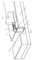
- the floor in front of the cutting device is pre-dissolved by two vertical swords. They at least partially project the earth body at a distance corresponding to that of the two following swords of the cutting device, the two following swords being connected by a third horizontal sword which then discharges the media lines.
- a transmitter is disposed on a sword of the precutting device and a receiver on a second blade.
- transmitters or receivers are arranged on the blades of the cutting device and / or the precutting device, while the corresponding receivers or transmitters are arranged on one or more further parallel-operated precutting devices and / or cutting devices. These can move in the same direction or in opposite directions parallel to each other.
- the ground is scanned for obstacles by radar sensors arranged on the earth's surface.
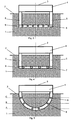
- the cutting device has a curved, semicircular or oval shape.
- the devices for discharging the media lines are now arranged symmetrically to a vertical, which runs from the earth's surface to the lowest point of the cutting device. In this way, layers are created in which the media lines are laid parallel to one another, axially spaced, wherein the axial distance of the media lines of a layer increases in the direction of the earth's surface.
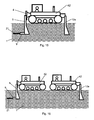
- the cutting device has a polygonal shape.
- the cutting device is advantageously formed symmetrically to a plane which is perpendicular to the earth's surface in the cutting direction.
- the devices for discharging the media lines are also arranged symmetrically to this plane. When laying thus arise layers in which the media lines are laid parallel to each other, axially spaced.
- Another preferred embodiment has a sword construction which has the shape of an inverted "Y". In this case, two more swords are attached to a vertical sword, which form an obtuse angle to the horizontal sword.
- the horizontal and vertical inclination of the cutting devices or of parts of the cutting devices can be changed.
- the cutting device advantageously has aids for better penetration of the soil.
- the cutting device on devices which act on the cutting device with vibrations, vibrations or shaking movements.
- friction-reducing agents are applied in the region of the blades of the cutting device (water, emulsions).
- the laying device carries prefabricated media lines in containers, such as cable drums or in exchangeable cassettes during the laying process. These containers can be easily and quickly changed and accelerate the work process.
- a container advantageously contains approximately 100 m of prefabricated media lines, which corresponds to the average laying length of a laying field.
Landscapes
- Engineering & Computer Science (AREA)
- Mechanical Engineering (AREA)
- Mining & Mineral Resources (AREA)
- Civil Engineering (AREA)
- General Engineering & Computer Science (AREA)
- Structural Engineering (AREA)
- Geophysics And Detection Of Objects (AREA)
- Road Repair (AREA)
- Road Paving Structures (AREA)
Claims (22)
- Dispositif de pose (3) pour la pose simultanée et sans contraintes d'au moins deux groupes (22), sensiblement parallèles et axialement distants, de conduites de fluide souples (21) en au moins une couche plane (A, B, C) dans le sol (1), sachant que chaque groupe (22) de conduites de fluide souples (21) présente au moins une conduite de fluide souple (21) et que le dispositif de pose (3) présente un dispositif de coupe (5, 9) pour produire au moins une entaille dans le sol (1), sachant que le dispositif de coupe (5, 9) présente exactement deux lames (5) disposées sensiblement verticalement et échelonnées en direction transversale, à l'extrémité inférieure desquelles est disposée une lame (9) orientée sensiblement horizontalement, qui présente au moins deux dispositifs (6, 7) pour larguer les groupes (22) de conduites de fluide (21) sur le côté opposé à la direction de coupe.
- Dispositif de pose (3) selon la revendication précédente, caractérisé en ce qu'un équipement de pré-coupe (12a, 12b) est disposé avant le dispositif de coupe (5, 9), considéré dans la direction de pose, équipement dont les lames (12a, 12b) correspondent totalement ou partiellement à celles du dispositif de coupe (5, 9).
- Dispositif de pose (3) selon l'une des revendications précédentes, caractérisé en ce que l'équipement de pré-coupe (12a, 12b) est disposé, considéré dans la direction de pose, sur le côté avant du dispositif de pose (3), et le dispositif de coupe (5, 9) sur le côté arrière.
- Dispositif de pose (3) selon l'une des revendications précédentes, caractérisé en ce que des mouvements directeurs horizontaux et/ou verticaux du dispositif de coupe (5, 9) sont réalisés par des mouvements d'inclinaison et/ou de rotation horizontaux et/ou verticaux des lames horizontales et/ou verticales (5, 9).
- Dispositif de pose (3) selon l'une des revendications précédentes, caractérisé en ce que les groupes de conduites de fluide sont dirigées à l'intérieur du dispositif de coupe jusqu'aux dispositifs pour larguer les groupes de conduites de fluide.
- Dispositif de pose (3) selon l'une des revendications précédentes, caractérisé en ce que des émetteurs (17) et/ou des récepteurs (18) de capteurs sont disposés sur une ou plusieurs des lames (5, 9) du dispositif de coupe (5, 9) et/ou de l'équipement de pré-coupe (12a, 12b).
- Dispositif de pose (3) selon l'une des revendications précédentes, caractérisé en ce que des émetteurs (17) et/ou des récepteurs (18) de capteurs sont disposés sur une ou plusieurs des lames (5, 9) du dispositif de coupe (5, 9) et/ou de l'équipement de pré-coupe (12a, 12b) d'un dispositif de pose (3), et leurs récepteurs (18) et/ou émetteurs (17) correspondants sont disposés sur une ou plusieurs des lames (5, 9) du dispositif de coupe (5, 9) et/ou de l'équipement de pré-coupe (12a, 12b) d'un dispositif de pose (3) dirigé en parallèle.
- Dispositif de pose (3) selon la revendication 6 ou 7, caractérisé en ce que des émetteurs (17) et/ou des récepteurs (18) de capteurs sont disposés sur une ou plusieurs des lames (5, 9) du dispositif de coupe (5, 9) et/ou de l'équipement de pré-coupe (12a, 12b) du dispositif de pose (3), et leurs récepteurs (18) et/ou émetteurs (17) correspondants sont disposés sur des postes de mesure fixes (20) sur le sol (1) et/ou dans le sol (1).
- Dispositif de pose (3) pour la pose simultanée et sans contraintes d'au moins deux groupes (22), sensiblement parallèles et axialement distants, de conduites de fluide souples (21) en au moins une couche plane (A, B, C) dans le sol (1), sachant que chaque groupe (22) de conduites de fluide souples (21) présente au moins une conduite de fluide souple (21) et que le dispositif de pose (3) présente un dispositif de coupe (8) pour produire au moins une entaille dans le sol (1), sachant que le dispositif de coupe (8) présente, considéré dans la direction de coupe, une conformation ronde, semi-circulaire, ovale, polygonale ou en Y et présente, sur le côté opposé à la direction de coupe, au moins deux dispositifs (6) pour larguer les groupes (22) de conduites de fluide (21), et sachant que les conduites de fluide sont dirigées à l'intérieur du dispositif de coupe jusqu'aux au moins deux dispositifs (6) pour larguer les groupes (22) de conduites de fluide (21).
- Dispositif de pose (3) selon l'une des revendications précédentes, caractérisé en ce que l'inclinaison horizontale et/ou verticale du dispositif de coupe (5, 8, 9) ou de parties du dispositif de coupe (5, 8, 9) peut être modifiée.
- Dispositif de pose (3) selon l'une des revendications précédentes, caractérisé en ce que le dispositif de coupe (5, 8, 9) est sollicité par des vibrations, des oscillations ou des secousses.
- Dispositif de pose (3) selon l'une des revendications précédentes, caractérisé en ce que les conduites de fluide préfabriquées (21) sont emportées avec le dispositif de pose (3) dans des récipients remplaçables, et sont dirigées hors des récipients dans le dispositif de coupe (5, 8, 9).
- Équipement porteur avec un dispositif de pose (3) selon l'une des revendications précédentes, caractérisé en ce que le dispositif de coupe (5, 8, 9) est disposé sur l'équipement porteur.
- Équipement porteur avec un dispositif de pose (3) selon la revendication 13, caractérisé en ce que des mouvements directeurs horizontaux et/ou verticaux du dispositif de coupe (5, 8, 9) sont réalisés par des mouvements d'inclinaison horizontaux et/ou verticaux de l'équipement porteur.
- Procédé pour poser à proximité de la surface des groupes axialement distants (22) de conduites de fluide souples au moyen d'un dispositif de pose (3) selon l'une des revendications 1 à 8 ainsi que 11 ou 12, caractérisé en ce que, en utilisant ce dispositif de pose (3) équipé du dispositif de coupe (5, 8, 9), on produit au moins une entaille dans le sol par les exactement deux lames (5) disposées sensiblement verticalement et échelonnées en direction transversale et par la lame (9) orientée sensiblement horizontalement à leur extrémité inférieure, et au moins deux groupes (22) de conduites de fluide (21) sont largués sur le côté opposé à la direction de coupe.
- Procédé selon la revendication 15, caractérisé en ce qu'on effectue une analyse physique du sol lors de la réalisation de l'entaille dans le sol.
- Procédé selon la revendication 15 ou 16, caractérisé en ce qu'avant, chronologiquement, l'utilisation du dispositif de coupe (5, 9), un équipement de pré-coupe (12a, 12b) ameublit le sol au moins partiellement aux endroits qui sont entaillés par les lames (5, 9) du dispositif de coupe (5, 9).
- Procédé selon l'une des revendications 15 à 17, caractérisé en ce que la profondeur de pose est modifiée en utilisant le dispositif de pose (3) à des positions de pose prédéfinies.
- Procédé selon l'une des revendications précédentes 15 à 18, caractérisé en ce qu'un moyen réduisant la friction est placé entre le dispositif de coupe (5, 9) et le sol (1).
- Utilisation d'un dispositif de pose (3) selon l'une des revendications 1 à 12 pour poser à proximité de la surface des groupes axialement distants (22) de tubes de drainage (21).
- Utilisation d'un dispositif de pose (3) selon la revendication 20 pour poser à proximité de la surface des groupes axialement distants (22) de conduites d'échangeur de chaleur (21) dans le sol (1), afin de récupérer l'énergie thermique proche de la surface (énergie agrothermique), à une profondeur comprise entre 0,5 m et 3,0 m.
- Utilisation d'un dispositif de pose (3) selon la revendication 20 ou 21, caractérisée en ce que le dispositif de pose (3) est utilisé plusieurs fois à différentes profondeurs sur la même zone, sachant que le dispositif de pose (3) accomplit chaque opération de pose suivante à une plus faible profondeur que l'opération de pose précédente.
Applications Claiming Priority (1)
| Application Number | Priority Date | Filing Date | Title |
|---|---|---|---|
| DE102009024323A DE102009024323A1 (de) | 2009-05-29 | 2009-05-29 | Verlegevorrichtung |
Publications (2)
| Publication Number | Publication Date |
|---|---|
| EP2256255A1 EP2256255A1 (fr) | 2010-12-01 |
| EP2256255B1 true EP2256255B1 (fr) | 2013-04-17 |
Family
ID=42562920
Family Applications (1)
| Application Number | Title | Priority Date | Filing Date |
|---|---|---|---|
| EP10164163.7A Active EP2256255B1 (fr) | 2009-05-29 | 2010-05-27 | Dispositif pour placer des câbles |
Country Status (4)
| Country | Link |
|---|---|
| US (1) | US8303216B2 (fr) |
| EP (1) | EP2256255B1 (fr) |
| DE (1) | DE102009024323A1 (fr) |
| DK (1) | DK2256255T3 (fr) |
Cited By (1)
| Publication number | Priority date | Publication date | Assignee | Title |
|---|---|---|---|---|
| DE102020119463A1 (de) | 2020-07-23 | 2022-01-27 | Doppelacker Gmbh | Verlegeverfahren und Verlegemaschine |
Families Citing this family (7)
| Publication number | Priority date | Publication date | Assignee | Title |
|---|---|---|---|---|
| US9562343B2 (en) * | 2013-10-16 | 2017-02-07 | Philip Paull | Cable-laying plow attachment for a backhoe and method for using the same |
| DE202016106622U1 (de) * | 2016-11-28 | 2016-12-06 | Walter Föckersperger | Verlegevorrichtung zur Erdverlegung flexibler Strangmaterialien |
| DE102017107608B3 (de) | 2017-04-10 | 2018-08-16 | Frank Föckersperger GmbH | Verfahren zum Einpflügen von Leitungen |
| DE102018119760A1 (de) * | 2018-08-14 | 2020-02-20 | Frank Föckersperger GmbH | Rohr- und/oder Kabelpflugsystem |
| DE102018119763A1 (de) * | 2018-08-14 | 2020-02-20 | Frank Föckersperger GmbH | Rohr- und/oder Kabelpflugsystem |
| EP3613906B1 (fr) | 2018-08-14 | 2023-06-21 | Frank Föckersperger GmbH | Système de charrue de tuyau et / ou de câble et procédé |
| DE102019123473B4 (de) * | 2019-09-02 | 2021-06-17 | Frank Föckersperger GmbH | Grabenfräse |
Family Cites Families (31)
| Publication number | Priority date | Publication date | Assignee | Title |
|---|---|---|---|---|
| NO121347B (fr) * | 1965-05-06 | 1971-02-15 | D Vaughan | |
| US3339369A (en) * | 1965-10-14 | 1967-09-05 | F B Ryan Mfg Company | Identification tape plow |
| US3590588A (en) * | 1968-07-01 | 1971-07-06 | Phillips Petroleum Co | Process and apparatus for laying a horizontal subterranean film |
| FR2102575A5 (fr) * | 1970-08-10 | 1972-04-07 | Pont A Mousson | |
| US3670512A (en) * | 1971-03-12 | 1972-06-20 | Service Dynamics Inc | Self-propelled cable burying apparatus |
| US3802210A (en) * | 1972-12-20 | 1974-04-09 | Andrea J D | Feed chute for underground cable laying plow |
| US3851489A (en) * | 1973-06-28 | 1974-12-03 | K Richardson | Line laying apparatus |
| US3849999A (en) * | 1973-11-02 | 1974-11-26 | E Coffey | Trailer type mole unit |
| AT328974B (de) * | 1974-05-10 | 1976-04-26 | Willner Kurt | Raumlicher pflugkorper fur die grabenlose verlegung von kabelartigen rohren |
| US3931717A (en) * | 1974-09-16 | 1976-01-13 | J. I. Case Company | Multiple cable chute |
| US3926004A (en) * | 1974-12-09 | 1975-12-16 | Case Co J I | Multi-cable laying blades or chutes |
| US4047387A (en) * | 1975-06-09 | 1977-09-13 | Kabushiki Kaisha Komatsu Seisakusho | Method of forming a subterranean water barrier and a plow for use therewith |
| IL48328A (en) * | 1975-10-20 | 1977-11-30 | Technion Res & Dev Foundation | Method of laying underground membranes |
| US4332511A (en) * | 1980-04-09 | 1982-06-01 | Bradley Dennis K | Cable burying apparatus |
| US4379655A (en) * | 1980-10-30 | 1983-04-12 | Phillips Petroleum Company | Process and apparatus for laying a subterranean film |
| US4637755A (en) * | 1983-02-17 | 1987-01-20 | Scott Tollefson | Apparatus for burying conduit |
| DE3335651C2 (de) * | 1983-09-30 | 1986-01-30 | Josef 8490 Cham Schmidbauer | Für Kabelpflüge dienende Lenkvorrichtung für Warnbänder |
| US4629363A (en) * | 1984-11-02 | 1986-12-16 | Rose Timothy M | Continuous conduit laying apparatus |
| DE3828595A1 (de) * | 1988-08-23 | 1990-03-08 | Gerold Meischen | Verfahren zum einpfluegen insbesondere von kabeln und verlegepflug zur durchfuehrung des verfahrens |
| GB9118848D0 (en) * | 1991-09-03 | 1991-10-16 | Davison Geoffrey W | Soil implement |
| DE4210858C2 (de) | 1992-04-01 | 2001-05-10 | Walter Foeckersperger | Kabelpflug |
| DE19623922C1 (de) * | 1996-06-15 | 1998-02-12 | Foeckersperger Georg Gmbh | Anordnung zum Einziehen eines Rohres in den Erdboden, sowie Anwendung einer solchen Anordnung |
| US5934833A (en) * | 1996-09-03 | 1999-08-10 | Installation Systems, A California Limited Liability Company | Vibratory pipe and cable laying plow |
| BE1011822A3 (nl) * | 1996-12-18 | 2000-02-01 | Dredging Int | Inrichting voor het in een te consolideren en te draineren slibmassa aanbrengen van een horizontaal net van draineerbuizen. |
| US5975804A (en) * | 1997-03-27 | 1999-11-02 | Bockman Enterprises, Inc. | Tile plow |
| US5913638A (en) * | 1998-02-04 | 1999-06-22 | Lansdale; Michael Lee | Sand channel trenching and pipe laying apparatus |
| DE19928683C2 (de) | 1999-06-23 | 2001-05-17 | Foeckersperger Georg Gmbh | Anordnung zum Einführen eines Rohres in den Erdboden |
| US20060051163A1 (en) * | 2004-08-31 | 2006-03-09 | Hagberg Gustav G | Grid master |
| US7524142B2 (en) * | 2005-05-31 | 2009-04-28 | Vermeer Manufacturing Company | Subsurface installation of tubing |
| US20070286681A1 (en) * | 2006-06-13 | 2007-12-13 | Michel Parent | Line laying apparatus |
| US7637697B1 (en) * | 2008-10-09 | 2009-12-29 | Holland Charles S | Trencher boot and methods of laying underground cable |
-
2009
- 2009-05-29 DE DE102009024323A patent/DE102009024323A1/de not_active Ceased
-
2010
- 2010-05-27 DK DK10164163.7T patent/DK2256255T3/da active
- 2010-05-27 EP EP10164163.7A patent/EP2256255B1/fr active Active
- 2010-05-28 US US12/789,475 patent/US8303216B2/en active Active
Cited By (2)
| Publication number | Priority date | Publication date | Assignee | Title |
|---|---|---|---|---|
| DE102020119463A1 (de) | 2020-07-23 | 2022-01-27 | Doppelacker Gmbh | Verlegeverfahren und Verlegemaschine |
| DE102020119463B4 (de) | 2020-07-23 | 2024-07-04 | Doppelacker Gmbh | Verlegeverfahren und Verlegemaschine |
Also Published As
| Publication number | Publication date |
|---|---|
| DE102009024323A1 (de) | 2011-01-05 |
| US20100310320A1 (en) | 2010-12-09 |
| EP2256255A1 (fr) | 2010-12-01 |
| US8303216B2 (en) | 2012-11-06 |
| DK2256255T3 (da) | 2013-07-22 |
Similar Documents
| Publication | Publication Date | Title |
|---|---|---|
| EP2256255B1 (fr) | Dispositif pour placer des câbles | |
| EP3198083B1 (fr) | Amortisseur de sons émis sous l'eau et procédé de manipulation d'un amortisseur de sons émis sous l'eau | |
| EP2441892B1 (fr) | Dispositif et procédé d'introduction de pieux dans le sol marin | |
| EP0548588B1 (fr) | Dispositif pour réaliser des forages dans le sol | |
| DE2647159A1 (de) | Verfahren zum verlegen von membranen im erdboden | |
| DE2162433C2 (de) | Bodenbearbeitungsmaschine | |
| DE1171968B (de) | Verfahren und Vorrichtung zum Einbetten einer Leitung, eines Kabels od. dgl. unter die Gelaende- oder Gewaessersohle | |
| DE2523340C3 (de) | Vorrichtung zum Verlegen eines Rohrstranges in einem Graben | |
| DE60118417T2 (de) | Verfahren und vorrichtung zur bodenverfestigung | |
| DE202018104669U1 (de) | Rohr- und/oder Kabelpflugsystem | |
| DE202021104394U1 (de) | Dammformgerät zum Herstellen von Dämmen, insbesondere Erdbeerdämmen | |
| DE202010007383U1 (de) | Verlegevorrichtung zum Verlegen eines Flachbandes im Erdreich | |
| DE102019123473B4 (de) | Grabenfräse | |
| DE102007050931B4 (de) | Überbohrkopf zum Verdrängen des eine Leitung umgebenden Erdreiches und Verfahren zum Überbohren | |
| DE3327061C2 (de) | Anordnung zum kontinuierlichen Verlegen von Kabeln, flexiblen Rohren oder dergleichen im Erdboden | |
| DE3914736A1 (de) | Verfahren und vorrichtung zum automatischen verlegen von rohren | |
| EP3613906B1 (fr) | Système de charrue de tuyau et / ou de câble et procédé | |
| EP2896752A1 (fr) | Procédé et système destinés à placer des conduites protégées contre des sollicitations mécaniques | |
| DE102021110776B4 (de) | Kabelpflugsystem | |
| DE1634999A1 (de) | Grabenraeumgeraet | |
| EP4100611B1 (fr) | Dispositif de pose de tuyaux dans le sol | |
| DE1634030A1 (de) | Verfahren und Einrichtung zum Verlegen eines Draenrohrstranges | |
| DE1484667A1 (de) | Verfahren zur selbsttaetigen Tiefensteuerung von Grabenziehmaschinen | |
| DE102017107608B3 (de) | Verfahren zum Einpflügen von Leitungen | |
| DE3730756A1 (de) | Vorrichtung zum einbringen einer langgestreckten sprengladung in den erdboden |
Legal Events
| Date | Code | Title | Description |
|---|---|---|---|
| PUAI | Public reference made under article 153(3) epc to a published international application that has entered the european phase |
Free format text: ORIGINAL CODE: 0009012 |
|
| AK | Designated contracting states |
Kind code of ref document: A1 Designated state(s): AL AT BE BG CH CY CZ DE DK EE ES FI FR GB GR HR HU IE IS IT LI LT LU LV MC MK MT NL NO PL PT RO SE SI SK SM TR |
|
| AX | Request for extension of the european patent |
Extension state: BA ME RS |
|
| 17P | Request for examination filed |
Effective date: 20101119 |
|
| 17Q | First examination report despatched |
Effective date: 20120326 |
|
| GRAP | Despatch of communication of intention to grant a patent |
Free format text: ORIGINAL CODE: EPIDOSNIGR1 |
|
| GRAS | Grant fee paid |
Free format text: ORIGINAL CODE: EPIDOSNIGR3 |
|
| GRAA | (expected) grant |
Free format text: ORIGINAL CODE: 0009210 |
|
| AK | Designated contracting states |
Kind code of ref document: B1 Designated state(s): AL AT BE BG CH CY CZ DE DK EE ES FI FR GB GR HR HU IE IS IT LI LT LU LV MC MK MT NL NO PL PT RO SE SI SK SM TR |
|
| REG | Reference to a national code |
Ref country code: GB Ref legal event code: FG4D Free format text: NOT ENGLISH |
|
| REG | Reference to a national code |
Ref country code: CH Ref legal event code: EP |
|
| REG | Reference to a national code |
Ref country code: IE Ref legal event code: FG4D Free format text: LANGUAGE OF EP DOCUMENT: GERMAN |
|
| REG | Reference to a national code |
Ref country code: AT Ref legal event code: REF Ref document number: 607403 Country of ref document: AT Kind code of ref document: T Effective date: 20130515 |
|
| REG | Reference to a national code |
Ref country code: DE Ref legal event code: R096 Ref document number: 502010002931 Country of ref document: DE Effective date: 20130613 |
|
| REG | Reference to a national code |
Ref country code: DK Ref legal event code: T3 |
|
| REG | Reference to a national code |
Ref country code: NL Ref legal event code: T3 |
|
| REG | Reference to a national code |
Ref country code: LT Ref legal event code: MG4D |
|
| PG25 | Lapsed in a contracting state [announced via postgrant information from national office to epo] |
Ref country code: GR Free format text: LAPSE BECAUSE OF FAILURE TO SUBMIT A TRANSLATION OF THE DESCRIPTION OR TO PAY THE FEE WITHIN THE PRESCRIBED TIME-LIMIT Effective date: 20130718 Ref country code: SE Free format text: LAPSE BECAUSE OF FAILURE TO SUBMIT A TRANSLATION OF THE DESCRIPTION OR TO PAY THE FEE WITHIN THE PRESCRIBED TIME-LIMIT Effective date: 20130417 Ref country code: LT Free format text: LAPSE BECAUSE OF FAILURE TO SUBMIT A TRANSLATION OF THE DESCRIPTION OR TO PAY THE FEE WITHIN THE PRESCRIBED TIME-LIMIT Effective date: 20130417 Ref country code: PT Free format text: LAPSE BECAUSE OF FAILURE TO SUBMIT A TRANSLATION OF THE DESCRIPTION OR TO PAY THE FEE WITHIN THE PRESCRIBED TIME-LIMIT Effective date: 20130819 Ref country code: SI Free format text: LAPSE BECAUSE OF FAILURE TO SUBMIT A TRANSLATION OF THE DESCRIPTION OR TO PAY THE FEE WITHIN THE PRESCRIBED TIME-LIMIT Effective date: 20130417 Ref country code: FI Free format text: LAPSE BECAUSE OF FAILURE TO SUBMIT A TRANSLATION OF THE DESCRIPTION OR TO PAY THE FEE WITHIN THE PRESCRIBED TIME-LIMIT Effective date: 20130417 Ref country code: ES Free format text: LAPSE BECAUSE OF FAILURE TO SUBMIT A TRANSLATION OF THE DESCRIPTION OR TO PAY THE FEE WITHIN THE PRESCRIBED TIME-LIMIT Effective date: 20130728 Ref country code: IS Free format text: LAPSE BECAUSE OF FAILURE TO SUBMIT A TRANSLATION OF THE DESCRIPTION OR TO PAY THE FEE WITHIN THE PRESCRIBED TIME-LIMIT Effective date: 20130817 Ref country code: NO Free format text: LAPSE BECAUSE OF FAILURE TO SUBMIT A TRANSLATION OF THE DESCRIPTION OR TO PAY THE FEE WITHIN THE PRESCRIBED TIME-LIMIT Effective date: 20130717 |
|
| PG25 | Lapsed in a contracting state [announced via postgrant information from national office to epo] |
Ref country code: HR Free format text: LAPSE BECAUSE OF FAILURE TO SUBMIT A TRANSLATION OF THE DESCRIPTION OR TO PAY THE FEE WITHIN THE PRESCRIBED TIME-LIMIT Effective date: 20130417 Ref country code: BG Free format text: LAPSE BECAUSE OF FAILURE TO SUBMIT A TRANSLATION OF THE DESCRIPTION OR TO PAY THE FEE WITHIN THE PRESCRIBED TIME-LIMIT Effective date: 20130717 Ref country code: LV Free format text: LAPSE BECAUSE OF FAILURE TO SUBMIT A TRANSLATION OF THE DESCRIPTION OR TO PAY THE FEE WITHIN THE PRESCRIBED TIME-LIMIT Effective date: 20130417 Ref country code: PL Free format text: LAPSE BECAUSE OF FAILURE TO SUBMIT A TRANSLATION OF THE DESCRIPTION OR TO PAY THE FEE WITHIN THE PRESCRIBED TIME-LIMIT Effective date: 20130417 Ref country code: CY Free format text: LAPSE BECAUSE OF FAILURE TO SUBMIT A TRANSLATION OF THE DESCRIPTION OR TO PAY THE FEE WITHIN THE PRESCRIBED TIME-LIMIT Effective date: 20130417 |
|
| BERE | Be: lapsed |
Owner name: DOPPELACKER G.M.B.H. Effective date: 20130531 Owner name: TECHNISCHE UNIVERSITAT DRESDEN Effective date: 20130531 |
|
| PG25 | Lapsed in a contracting state [announced via postgrant information from national office to epo] |
Ref country code: MC Free format text: LAPSE BECAUSE OF FAILURE TO SUBMIT A TRANSLATION OF THE DESCRIPTION OR TO PAY THE FEE WITHIN THE PRESCRIBED TIME-LIMIT Effective date: 20130417 Ref country code: SK Free format text: LAPSE BECAUSE OF FAILURE TO SUBMIT A TRANSLATION OF THE DESCRIPTION OR TO PAY THE FEE WITHIN THE PRESCRIBED TIME-LIMIT Effective date: 20130417 Ref country code: CZ Free format text: LAPSE BECAUSE OF FAILURE TO SUBMIT A TRANSLATION OF THE DESCRIPTION OR TO PAY THE FEE WITHIN THE PRESCRIBED TIME-LIMIT Effective date: 20130417 Ref country code: EE Free format text: LAPSE BECAUSE OF FAILURE TO SUBMIT A TRANSLATION OF THE DESCRIPTION OR TO PAY THE FEE WITHIN THE PRESCRIBED TIME-LIMIT Effective date: 20130417 |
|
| PLBE | No opposition filed within time limit |
Free format text: ORIGINAL CODE: 0009261 |
|
| STAA | Information on the status of an ep patent application or granted ep patent |
Free format text: STATUS: NO OPPOSITION FILED WITHIN TIME LIMIT |
|
| REG | Reference to a national code |
Ref country code: IE Ref legal event code: MM4A |
|
| PG25 | Lapsed in a contracting state [announced via postgrant information from national office to epo] |
Ref country code: RO Free format text: LAPSE BECAUSE OF FAILURE TO SUBMIT A TRANSLATION OF THE DESCRIPTION OR TO PAY THE FEE WITHIN THE PRESCRIBED TIME-LIMIT Effective date: 20130417 Ref country code: IT Free format text: LAPSE BECAUSE OF FAILURE TO SUBMIT A TRANSLATION OF THE DESCRIPTION OR TO PAY THE FEE WITHIN THE PRESCRIBED TIME-LIMIT Effective date: 20130417 Ref country code: BE Free format text: LAPSE BECAUSE OF NON-PAYMENT OF DUE FEES Effective date: 20130531 |
|
| REG | Reference to a national code |
Ref country code: FR Ref legal event code: ST Effective date: 20140131 |
|
| 26N | No opposition filed |
Effective date: 20140120 |
|
| PG25 | Lapsed in a contracting state [announced via postgrant information from national office to epo] |
Ref country code: IE Free format text: LAPSE BECAUSE OF NON-PAYMENT OF DUE FEES Effective date: 20130527 |
|
| REG | Reference to a national code |
Ref country code: DE Ref legal event code: R097 Ref document number: 502010002931 Country of ref document: DE Effective date: 20140120 |
|
| PG25 | Lapsed in a contracting state [announced via postgrant information from national office to epo] |
Ref country code: FR Free format text: LAPSE BECAUSE OF NON-PAYMENT OF DUE FEES Effective date: 20130617 |
|
| REG | Reference to a national code |
Ref country code: CH Ref legal event code: PL |
|
| GBPC | Gb: european patent ceased through non-payment of renewal fee |
Effective date: 20140527 |
|
| PG25 | Lapsed in a contracting state [announced via postgrant information from national office to epo] |
Ref country code: CH Free format text: LAPSE BECAUSE OF NON-PAYMENT OF DUE FEES Effective date: 20140531 Ref country code: LI Free format text: LAPSE BECAUSE OF NON-PAYMENT OF DUE FEES Effective date: 20140531 |
|
| PG25 | Lapsed in a contracting state [announced via postgrant information from national office to epo] |
Ref country code: MT Free format text: LAPSE BECAUSE OF FAILURE TO SUBMIT A TRANSLATION OF THE DESCRIPTION OR TO PAY THE FEE WITHIN THE PRESCRIBED TIME-LIMIT Effective date: 20130417 |
|
| PG25 | Lapsed in a contracting state [announced via postgrant information from national office to epo] |
Ref country code: SM Free format text: LAPSE BECAUSE OF FAILURE TO SUBMIT A TRANSLATION OF THE DESCRIPTION OR TO PAY THE FEE WITHIN THE PRESCRIBED TIME-LIMIT Effective date: 20130417 Ref country code: GB Free format text: LAPSE BECAUSE OF NON-PAYMENT OF DUE FEES Effective date: 20140527 |
|
| PG25 | Lapsed in a contracting state [announced via postgrant information from national office to epo] |
Ref country code: TR Free format text: LAPSE BECAUSE OF FAILURE TO SUBMIT A TRANSLATION OF THE DESCRIPTION OR TO PAY THE FEE WITHIN THE PRESCRIBED TIME-LIMIT Effective date: 20130417 |
|
| PG25 | Lapsed in a contracting state [announced via postgrant information from national office to epo] |
Ref country code: HU Free format text: LAPSE BECAUSE OF FAILURE TO SUBMIT A TRANSLATION OF THE DESCRIPTION OR TO PAY THE FEE WITHIN THE PRESCRIBED TIME-LIMIT; INVALID AB INITIO Effective date: 20100527 Ref country code: MK Free format text: LAPSE BECAUSE OF FAILURE TO SUBMIT A TRANSLATION OF THE DESCRIPTION OR TO PAY THE FEE WITHIN THE PRESCRIBED TIME-LIMIT Effective date: 20130417 Ref country code: LU Free format text: LAPSE BECAUSE OF NON-PAYMENT OF DUE FEES Effective date: 20130527 |
|
| PGFP | Annual fee paid to national office [announced via postgrant information from national office to epo] |
Ref country code: NL Payment date: 20180424 Year of fee payment: 9 |
|
| PGFP | Annual fee paid to national office [announced via postgrant information from national office to epo] |
Ref country code: DK Payment date: 20180518 Year of fee payment: 9 |
|
| PGFP | Annual fee paid to national office [announced via postgrant information from national office to epo] |
Ref country code: AT Payment date: 20180514 Year of fee payment: 9 |
|
| PG25 | Lapsed in a contracting state [announced via postgrant information from national office to epo] |
Ref country code: AL Free format text: LAPSE BECAUSE OF FAILURE TO SUBMIT A TRANSLATION OF THE DESCRIPTION OR TO PAY THE FEE WITHIN THE PRESCRIBED TIME-LIMIT Effective date: 20130417 |
|
| REG | Reference to a national code |
Ref country code: DK Ref legal event code: EBP Effective date: 20190531 |
|
| REG | Reference to a national code |
Ref country code: NL Ref legal event code: MM Effective date: 20190601 |
|
| REG | Reference to a national code |
Ref country code: AT Ref legal event code: MM01 Ref document number: 607403 Country of ref document: AT Kind code of ref document: T Effective date: 20190527 |
|
| PG25 | Lapsed in a contracting state [announced via postgrant information from national office to epo] |
Ref country code: AT Free format text: LAPSE BECAUSE OF NON-PAYMENT OF DUE FEES Effective date: 20190527 |
|
| PG25 | Lapsed in a contracting state [announced via postgrant information from national office to epo] |
Ref country code: DK Free format text: LAPSE BECAUSE OF NON-PAYMENT OF DUE FEES Effective date: 20190531 Ref country code: NL Free format text: LAPSE BECAUSE OF NON-PAYMENT OF DUE FEES Effective date: 20190601 |
|
| PGFP | Annual fee paid to national office [announced via postgrant information from national office to epo] |
Ref country code: DE Payment date: 20240419 Year of fee payment: 15 |