EP2256085A2 - Verfahren und Vorrichtung zur katalytischen Oxidation von SO2-haltigen Gasen mit Sauerstoff - Google Patents
Verfahren und Vorrichtung zur katalytischen Oxidation von SO2-haltigen Gasen mit Sauerstoff Download PDFInfo
- Publication number
- EP2256085A2 EP2256085A2 EP10172657A EP10172657A EP2256085A2 EP 2256085 A2 EP2256085 A2 EP 2256085A2 EP 10172657 A EP10172657 A EP 10172657A EP 10172657 A EP10172657 A EP 10172657A EP 2256085 A2 EP2256085 A2 EP 2256085A2
- Authority
- EP
- European Patent Office
- Prior art keywords
- tube
- catalyst
- gas
- sulfur dioxide
- vol
- Prior art date
- Legal status (The legal status is an assumption and is not a legal conclusion. Google has not performed a legal analysis and makes no representation as to the accuracy of the status listed.)
- Granted
Links
Images


Classifications
-
- C—CHEMISTRY; METALLURGY
- C01—INORGANIC CHEMISTRY
- C01B—NON-METALLIC ELEMENTS; COMPOUNDS THEREOF; METALLOIDS OR COMPOUNDS THEREOF NOT COVERED BY SUBCLASS C01C
- C01B17/00—Sulfur; Compounds thereof
- C01B17/69—Sulfur trioxide; Sulfuric acid
- C01B17/74—Preparation
- C01B17/76—Preparation by contact processes
- C01B17/765—Multi-stage SO3-conversion
- C01B17/7655—Multi-stage SO3-conversion with intermediate absorption
-
- B—PERFORMING OPERATIONS; TRANSPORTING
- B01—PHYSICAL OR CHEMICAL PROCESSES OR APPARATUS IN GENERAL
- B01J—CHEMICAL OR PHYSICAL PROCESSES, e.g. CATALYSIS OR COLLOID CHEMISTRY; THEIR RELEVANT APPARATUS
- B01J8/00—Chemical or physical processes in general, conducted in the presence of fluids and solid particles; Apparatus for such processes
- B01J8/02—Chemical or physical processes in general, conducted in the presence of fluids and solid particles; Apparatus for such processes with stationary particles, e.g. in fixed beds
- B01J8/06—Chemical or physical processes in general, conducted in the presence of fluids and solid particles; Apparatus for such processes with stationary particles, e.g. in fixed beds in tube reactors; the solid particles being arranged in tubes
-
- B—PERFORMING OPERATIONS; TRANSPORTING
- B01—PHYSICAL OR CHEMICAL PROCESSES OR APPARATUS IN GENERAL
- B01D—SEPARATION
- B01D53/00—Separation of gases or vapours; Recovering vapours of volatile solvents from gases; Chemical or biological purification of waste gases, e.g. engine exhaust gases, smoke, fumes, flue gases, aerosols
- B01D53/34—Chemical or biological purification of waste gases
- B01D53/74—General processes for purification of waste gases; Apparatus or devices specially adapted therefor
- B01D53/75—Multi-step processes
-
- B—PERFORMING OPERATIONS; TRANSPORTING
- B01—PHYSICAL OR CHEMICAL PROCESSES OR APPARATUS IN GENERAL
- B01D—SEPARATION
- B01D53/00—Separation of gases or vapours; Recovering vapours of volatile solvents from gases; Chemical or biological purification of waste gases, e.g. engine exhaust gases, smoke, fumes, flue gases, aerosols
- B01D53/34—Chemical or biological purification of waste gases
- B01D53/74—General processes for purification of waste gases; Apparatus or devices specially adapted therefor
- B01D53/86—Catalytic processes
- B01D53/8603—Removing sulfur compounds
- B01D53/8609—Sulfur oxides
-
- B—PERFORMING OPERATIONS; TRANSPORTING
- B01—PHYSICAL OR CHEMICAL PROCESSES OR APPARATUS IN GENERAL
- B01J—CHEMICAL OR PHYSICAL PROCESSES, e.g. CATALYSIS OR COLLOID CHEMISTRY; THEIR RELEVANT APPARATUS
- B01J8/00—Chemical or physical processes in general, conducted in the presence of fluids and solid particles; Apparatus for such processes
- B01J8/02—Chemical or physical processes in general, conducted in the presence of fluids and solid particles; Apparatus for such processes with stationary particles, e.g. in fixed beds
- B01J8/04—Chemical or physical processes in general, conducted in the presence of fluids and solid particles; Apparatus for such processes with stationary particles, e.g. in fixed beds the fluid passing successively through two or more beds
- B01J8/0446—Chemical or physical processes in general, conducted in the presence of fluids and solid particles; Apparatus for such processes with stationary particles, e.g. in fixed beds the fluid passing successively through two or more beds the flow within the beds being predominantly vertical
- B01J8/0476—Chemical or physical processes in general, conducted in the presence of fluids and solid particles; Apparatus for such processes with stationary particles, e.g. in fixed beds the fluid passing successively through two or more beds the flow within the beds being predominantly vertical in two or more otherwise shaped beds
- B01J8/048—Chemical or physical processes in general, conducted in the presence of fluids and solid particles; Apparatus for such processes with stationary particles, e.g. in fixed beds the fluid passing successively through two or more beds the flow within the beds being predominantly vertical in two or more otherwise shaped beds the beds being superimposed one above the other
-
- B—PERFORMING OPERATIONS; TRANSPORTING
- B01—PHYSICAL OR CHEMICAL PROCESSES OR APPARATUS IN GENERAL
- B01J—CHEMICAL OR PHYSICAL PROCESSES, e.g. CATALYSIS OR COLLOID CHEMISTRY; THEIR RELEVANT APPARATUS
- B01J8/00—Chemical or physical processes in general, conducted in the presence of fluids and solid particles; Apparatus for such processes
- B01J8/02—Chemical or physical processes in general, conducted in the presence of fluids and solid particles; Apparatus for such processes with stationary particles, e.g. in fixed beds
- B01J8/04—Chemical or physical processes in general, conducted in the presence of fluids and solid particles; Apparatus for such processes with stationary particles, e.g. in fixed beds the fluid passing successively through two or more beds
- B01J8/0446—Chemical or physical processes in general, conducted in the presence of fluids and solid particles; Apparatus for such processes with stationary particles, e.g. in fixed beds the fluid passing successively through two or more beds the flow within the beds being predominantly vertical
- B01J8/0476—Chemical or physical processes in general, conducted in the presence of fluids and solid particles; Apparatus for such processes with stationary particles, e.g. in fixed beds the fluid passing successively through two or more beds the flow within the beds being predominantly vertical in two or more otherwise shaped beds
- B01J8/0488—Chemical or physical processes in general, conducted in the presence of fluids and solid particles; Apparatus for such processes with stationary particles, e.g. in fixed beds the fluid passing successively through two or more beds the flow within the beds being predominantly vertical in two or more otherwise shaped beds the beds being placed in separate reactors
-
- B—PERFORMING OPERATIONS; TRANSPORTING
- B01—PHYSICAL OR CHEMICAL PROCESSES OR APPARATUS IN GENERAL
- B01J—CHEMICAL OR PHYSICAL PROCESSES, e.g. CATALYSIS OR COLLOID CHEMISTRY; THEIR RELEVANT APPARATUS
- B01J8/00—Chemical or physical processes in general, conducted in the presence of fluids and solid particles; Apparatus for such processes
- B01J8/02—Chemical or physical processes in general, conducted in the presence of fluids and solid particles; Apparatus for such processes with stationary particles, e.g. in fixed beds
- B01J8/04—Chemical or physical processes in general, conducted in the presence of fluids and solid particles; Apparatus for such processes with stationary particles, e.g. in fixed beds the fluid passing successively through two or more beds
- B01J8/0496—Heating or cooling the reactor
-
- B—PERFORMING OPERATIONS; TRANSPORTING
- B01—PHYSICAL OR CHEMICAL PROCESSES OR APPARATUS IN GENERAL
- B01J—CHEMICAL OR PHYSICAL PROCESSES, e.g. CATALYSIS OR COLLOID CHEMISTRY; THEIR RELEVANT APPARATUS
- B01J8/00—Chemical or physical processes in general, conducted in the presence of fluids and solid particles; Apparatus for such processes
- B01J8/02—Chemical or physical processes in general, conducted in the presence of fluids and solid particles; Apparatus for such processes with stationary particles, e.g. in fixed beds
- B01J8/06—Chemical or physical processes in general, conducted in the presence of fluids and solid particles; Apparatus for such processes with stationary particles, e.g. in fixed beds in tube reactors; the solid particles being arranged in tubes
- B01J8/067—Heating or cooling the reactor
-
- C—CHEMISTRY; METALLURGY
- C01—INORGANIC CHEMISTRY
- C01B—NON-METALLIC ELEMENTS; COMPOUNDS THEREOF; METALLOIDS OR COMPOUNDS THEREOF NOT COVERED BY SUBCLASS C01C
- C01B17/00—Sulfur; Compounds thereof
- C01B17/69—Sulfur trioxide; Sulfuric acid
- C01B17/74—Preparation
- C01B17/76—Preparation by contact processes
- C01B17/765—Multi-stage SO3-conversion
-
- C—CHEMISTRY; METALLURGY
- C01—INORGANIC CHEMISTRY
- C01B—NON-METALLIC ELEMENTS; COMPOUNDS THEREOF; METALLOIDS OR COMPOUNDS THEREOF NOT COVERED BY SUBCLASS C01C
- C01B17/00—Sulfur; Compounds thereof
- C01B17/69—Sulfur trioxide; Sulfuric acid
- C01B17/74—Preparation
- C01B17/76—Preparation by contact processes
- C01B17/78—Preparation by contact processes characterised by the catalyst used
- C01B17/79—Preparation by contact processes characterised by the catalyst used containing vanadium
-
- C—CHEMISTRY; METALLURGY
- C01—INORGANIC CHEMISTRY
- C01B—NON-METALLIC ELEMENTS; COMPOUNDS THEREOF; METALLOIDS OR COMPOUNDS THEREOF NOT COVERED BY SUBCLASS C01C
- C01B17/00—Sulfur; Compounds thereof
- C01B17/69—Sulfur trioxide; Sulfuric acid
- C01B17/74—Preparation
- C01B17/76—Preparation by contact processes
- C01B17/80—Apparatus
-
- C—CHEMISTRY; METALLURGY
- C01—INORGANIC CHEMISTRY
- C01B—NON-METALLIC ELEMENTS; COMPOUNDS THEREOF; METALLOIDS OR COMPOUNDS THEREOF NOT COVERED BY SUBCLASS C01C
- C01B17/00—Sulfur; Compounds thereof
- C01B17/69—Sulfur trioxide; Sulfuric acid
- C01B17/74—Preparation
- C01B17/76—Preparation by contact processes
- C01B17/80—Apparatus
- C01B17/803—Converters
-
- B—PERFORMING OPERATIONS; TRANSPORTING
- B01—PHYSICAL OR CHEMICAL PROCESSES OR APPARATUS IN GENERAL
- B01D—SEPARATION
- B01D2255/00—Catalysts
- B01D2255/20—Metals or compounds thereof
- B01D2255/207—Transition metals
- B01D2255/20723—Vanadium
-
- B—PERFORMING OPERATIONS; TRANSPORTING
- B01—PHYSICAL OR CHEMICAL PROCESSES OR APPARATUS IN GENERAL
- B01J—CHEMICAL OR PHYSICAL PROCESSES, e.g. CATALYSIS OR COLLOID CHEMISTRY; THEIR RELEVANT APPARATUS
- B01J2208/00—Processes carried out in the presence of solid particles; Reactors therefor
- B01J2208/00008—Controlling the process
- B01J2208/00017—Controlling the temperature
- B01J2208/00106—Controlling the temperature by indirect heat exchange
- B01J2208/00168—Controlling the temperature by indirect heat exchange with heat exchange elements outside the bed of solid particles
- B01J2208/00176—Controlling the temperature by indirect heat exchange with heat exchange elements outside the bed of solid particles outside the reactor
-
- B—PERFORMING OPERATIONS; TRANSPORTING
- B01—PHYSICAL OR CHEMICAL PROCESSES OR APPARATUS IN GENERAL
- B01J—CHEMICAL OR PHYSICAL PROCESSES, e.g. CATALYSIS OR COLLOID CHEMISTRY; THEIR RELEVANT APPARATUS
- B01J2208/00—Processes carried out in the presence of solid particles; Reactors therefor
- B01J2208/00008—Controlling the process
- B01J2208/00017—Controlling the temperature
- B01J2208/00106—Controlling the temperature by indirect heat exchange
- B01J2208/00168—Controlling the temperature by indirect heat exchange with heat exchange elements outside the bed of solid particles
- B01J2208/00203—Coils
-
- B—PERFORMING OPERATIONS; TRANSPORTING
- B01—PHYSICAL OR CHEMICAL PROCESSES OR APPARATUS IN GENERAL
- B01J—CHEMICAL OR PHYSICAL PROCESSES, e.g. CATALYSIS OR COLLOID CHEMISTRY; THEIR RELEVANT APPARATUS
- B01J2219/00—Chemical, physical or physico-chemical processes in general; Their relevant apparatus
- B01J2219/00002—Chemical plants
- B01J2219/00004—Scale aspects
- B01J2219/00006—Large-scale industrial plants
Definitions
- the invention relates to a method and a device for the catalytic oxidation of 0.1 to 66 vol% SO 2 -containing gases with oxygen in a quasi-isothermally operated tube contact apparatus (QIK) under indirect cooling or heating to maintain the desired working temperature of the catalyst.
- QIK quasi-isothermally operated tube contact apparatus
- sulfuric acid is usually produced in the large-scale plant by the so-called double contact process in a reactor comprising one or more catalyst-containing contact stages (described, for example, in US Pat Ullmann's Encyclopedia of Industrial Chemistry ).
- the reaction is so exothermic that the catalyst forms so-called hot spots and is irreversibly damaged.
- the plants of the prior art to avoid irreversible damage to the catalyst at T ⁇ 640 ° C with SO 2 contents ⁇ 13.5 vol.% Operated in the starting gas.
- the starting gas inlet temperature T> 380 ° C and the SO 2 content must be> about 5 vol.%.
- DE-OS 2026818 describes a method in which weight the starting gases before entering the first contact stage with sprouted from oleum and additional dilution air SO 3 to SO 2 concentration of 10-20.% are diluted.
- the disadvantage here is the costly high cost and the specific low SO 2 conversion in the first contact stage.
- DE-10249782 describes a process for the production of sulfuric acid based on concentrated starting gases SO 2 > 13.5 vol.% in a reactor having a plurality of contact stages, which can be run with relatively smaller amounts of dilution air.
- the dilution in the first contact stage is achieved by recycling a partially oxidized gas stream. From one of the last main contact stage upstream contact stages, a partial stream of the SO 2 / SO 3 -containing gas is withdrawn.
- a disadvantage of this method is the high expenditure on equipment.
- GB1504725A discloses an apparatus and method for producing sulfur trioxide from technically pure sulfur dioxide and technical oxygen in a tubular heat exchanger. From the description (page 2, line 17) it can be seen that the heat exchanger has an outer jacket in which the heat transfer medium is guided and comprises an inner, catalyst-filled tube to which heat can be supplied by means of the heat transfer medium or removed from the heat. GB1504725A discloses that the heat exchanger may comprise more than one reaction tube; however, it is not disclosed how a heat exchanger having a plurality of reaction tubes is designed.
- the object was achieved by a quasi-isothermal process management with energy supply or -abschreib, preferably via an intermediate circuit and preferably in a tube contact apparatus, solved.
- the process according to the invention makes it possible to convert starting gases having a content of 0.1 ⁇ SO 2 ⁇ 66% by volume, at least partially, into sulfur trioxide by oxidation with oxygen on the catalyst.
- the present invention is therefore a process for the continuous catalytic, complete or partial oxidation of a starting gas containing sulfur dioxide and oxygen, characterized in that the catalyst is kept active with a quasi-isothermal process management with energy supply or -Abschreib.
- a further subject of the present invention is an apparatus for the continuous catalytic, complete or partial oxidation of a starting gas containing sulfur dioxide and oxygen, characterized by at least one tube contact apparatus, which is a stationary heat exchanger comprising at least one double-walled tube, whose inner tube filled with catalyst forms a reaction tube, wherein the heat is transferred to the reaction tube by means of a cooling medium and the tube contactor, an absorber for the separation of SO 3 can be connected downstream.
- a tube contact apparatus which is a stationary heat exchanger comprising at least one double-walled tube, whose inner tube filled with catalyst forms a reaction tube, wherein the heat is transferred to the reaction tube by means of a cooling medium and the tube contactor, an absorber for the separation of SO 3 can be connected downstream.
- the tube contact apparatus is a stationary heat exchanger of a plurality of double-walled tubes having an inner tube and an outer tube, wherein a catalyst is filled in the inner tubes and the heat transfer to these inner tubes / reaction tubes by a co-cooled cooling medium in the space between inner and outer tube takes place.
- the method according to the invention is carried out in one of the embodiments of the device according to the invention.
- the method according to the invention is carried out in a tube contact apparatus.
- the energy supply or -Abschreib via an intermediate circuit is carried out in one of the embodiments of the device according to the invention.
- the temperature window which is established and, in particular, the maximum temperature within defined limits with respect to the sulfur dioxide concentration are determined essentially in the design phase.
- Essential parameters are gas inlet temperature, gas velocity, catalyst dilution, tube geometry and cooling capacity.
- the conditions in the intermediate circuit are usually adjusted so that the catalyst does not exceed the harmful limit of 640 ° C at any point when using a Vanadiumpentoxidkatalysators with or without cesium.
- the conditions are adjusted so that the adjusting temperature profile over the tube length is adjusted so that the inlet temperature of 380 ° C to 450 ° C, preferably 400 ° C to 450 ° C, the outlet temperature in a range of 430 ° C - 500th ° C and a maximum temperature not higher than 580 ° C lie.
- a cesium-doped vanadium pentoxide catalyst having 5-10%, preferably 6-8%, particularly preferably with 7.5% cesium for low gas inlet temperatures of 360-450 ° C, preferably 370-450 ° C, particularly preferably used 380-450 ° C.
- the tube contactor has reaction tubes with nominal diameters of 25 mm to 150 mm, preferably 50 mm to 80 mm with tube lengths of 1 m to 12 m, preferably 2 m to 6 m.
- the catalyst consists of a catalytically active metal or metal derivatives, optionally applied with promoters on a catalyst support material.
- the catalyst V 2 O 5 is supported with potassium and sodium salts on SiO 2 .
- the catalyst with a temperature-resistant inert material, in particular the pure catalyst support material such.
- a temperature-resistant inert material in particular the pure catalyst support material such.
- the pure catalyst support material such as glass, SiO 2 , Al 2 O 3 or other common oxides, ceramics, silica gel or zeolites, preferably glass and ceramic, mixed.
- the catalyst used in its reactivity by mixing with the inert material in the ratio of 1: 100 to 100: 1 1 preset.
- Inert material and catalyst are preferably mixed in quantitative ratios 90:10 to 40:60, more preferably 80:20 to 40:60.
- the designed apparatus design such as tube length, tube diameter, degree of dilution of the catalyst, tube flow due to the kinetics sets a maximum temperature, the heat removal is of particular importance.
- the leadership of the cooling medium can be carried out in cross, counter or DC. Due to the exothermic reaction process, the preferred embodiment is the DC current. It offers significant advantages in terms of safely avoiding local temperature excesses on the catalyst and with respect to the mass flow of the circulating cooling medium
- the double-jacket construction is selected such that, based on the operating parameters and selected pipe pairings (inner pipe and outer pipe), a heat transfer coefficient (alpha values) of 20 to 80 W / m 2 K, preferably 40 to 70 W / m 2 K, is established ,
- a heat transfer coefficient alpha values
- the heat to be dissipated from the cooling circuit operation at the temperature level of about 220 ° C. to 550 ° C., preferably from 300 ° C. to 450 ° C., can preferably be decoupled via a heat exchanger as low-pressure steam for further operational use.
- the tube contact apparatus can be combined with a conventional contact system, preferably with a double contact system and at least one oleum / intermediate absorber, a contact stage and an end absorber.
- the tube contact apparatus is connected upstream of the classic double contact system.
- the tube contact apparatus is preferably followed by a pre-absorber.
- the pre-, oleum / intermediate and final absorbers remove the produced SO 3 from the gas stream.
- the gases whose sulfur dioxide inlet concentrations were reduced to 5 to 13% by volume with the aid of the process according to the invention can be further treated in the downstream double contact plant according to the prior art.
- tube contact apparatus and a conventional contact system are coupled from one or more contact stages, the same catalyst is usefully used in the tube contact apparatus with regard to the chemical composition as in the contact stages of the contact system.
- the method depending on the underlying SO 2 input concentration in the starting gas and the type of system required so new installation or retrofitting an existing system, can be realized in different concepts.
- the vanadium pentoxide catalyst with or without cesium by continuous heat via the indirect heating circuit to a favorable temperature for the reaction of 450 ° C to 580 ° C are maintained.
- the resulting SO 3 is freed of sulfur trioxide in a final absorber according to the prior art.
- the unreacted sulfur dioxide fraction can be finally purified to the required legal emission limit values in a final gas scrubber, for example catalytically on wet activated carbon or other conventional processes.
- the inventive method allows in a quasi-isothermally operated tube contact apparatus sulfur dioxide by oxidation to sulfur trioxide, using z. B of conventional vanadium pentoxide catalysts with or without cesium with a high conversion (> 90%) to process in an apparatus, while high flexibility with respect to the input sulfur dioxide concentrations.
- Another great advantage of the method according to the invention is its environmental friendliness.
- the SO 2 can be converted to nearly 100% sulfuric acid.
- For starting gases having a sulfur dioxide concentration greater than 5 vol.% Of the catalyst can be maintained by continuous heat removal via the indirect cooling circuit to a favorable temperature for the reaction of 420 ° C to 600 ° C.
- the inventive method allows sulfur dioxide by oxidation to sulfur trioxide using z.
- Another advantage of the method according to the invention is when an existing system according to the double contact method with respect to the sulfur dioxide conversion by increasing the SO 2 inlet concentration to be significantly expanded to more than 13.5 vol.%.
- a partial flow can be treated by connecting a quasi-isothermally operated tube contact apparatus such that after reuniting of both partial flows, an SO 2 concentration of less than 13 vol.% SO 2 is formed (bypass circuit, Fig. 2 ).
- the gas pretreated by the process according to the invention can then be successfully treated further in the classical double contact plant.
- a conventional double-contact system may use a tube contactor in series (ie without a bypass, such as in FIG Fig. 3 shown).
- contact gases having a sulfur dioxide content of 13.5 to 30% by volume, preferably between 15 and 25% by volume, can be supplied in the tube contact apparatus.
- higher SO 2 input concentrations z. B. be processed from 30 to 66 vol.%
- the ratio of O 2 to SO 2 in the contact gas is usually 0.5 to 1.2, and more preferably 0.7 to 0.9.
- the process is controlled by setpoint control of the cooling circuit so that the gases leaving the apparatus with respect to the SO 2 concentration are adjusted so that the conditions of the downstream main contact stages, (SO 2 concentration ⁇ 13 vol. %) are fulfilled.
- the gases are preferably at least partially freed from the sulfur trioxide in a pre-absorber according to the prior art before they are passed into the first main contact stage for further oxidation of the sulfur dioxide.
- the main contacts are usually operated as in the conventional method.
- a conventional plant can be improved to a flexible production plant with higher capacity and low investment.
- the process according to the invention enables the direct production of oleum 35% and oleum 65% with the elimination of a distillation stage and by partial condensation the production of oleum 100%.
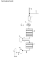
- Fig. 1 a plant according to the so-called double contact process for the production of sulfuric acid according to the prior art is shown (see also Ullmann's Encyclopedia of Industrial Chemistry).
- It consists of a gas dryer 1, a gas preheater 2, a first main contact 3 with up to three catalyst stacks, an oleum / intermediate absorber 5, a second main contact 4 with up to two catalyst stacks and an end absorber . 6
- the exhaust gas is discharged through fireplace 7 to the environment.
- Starting gas with less than 13.5 vol.% SO 2 is introduced via the line a and diluted before entry into the gas dryer 1 with air supplied via line b with respect to the SO 2 concentration to ⁇ 13 vol.% SO 2 .
- the dried gas mixture is then preheated in the gas preheater 2 to the required inlet temperature of the first Katalysatorhorde and fed via the line c the first main contact 3 , in which runs in succession up to three Katalysatorhorden with intermediate cooling the exothermic oxidation reaction.
- the escaping gas is fed via line e to an oleum / intermediate absorber 5 .
- the majority of the sulfur trioxide formed in the first main contact 3 with the water in the Umpump Vietnameselauf the oleum / intermediate absorber 5 is absorbed to form sulfuric acid.
- the gas is then passed via line f into the second main contact 4 , by the further exothermic oxidation reaction takes place in succession up to two catalyst hordes. Subsequently, the gas is supplied via the line g to the end absorber 6 , in which the residual sulfur trioxide formed is absorbed to form sulfuric acid.
- the exhaust gas is fed to the chimney 7 and leaves here the plant.
- the sulfuric acid produced in the oleum / intermediate absorber 5 and final absorber 6 is discharged from the plant.
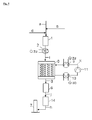
- Fig. 2 represents a first embodiment of the method according to the invention for the partial gas treatment of starting gases with more than 13.5 vol.% Sulfur dioxide by means of a bypass circuit.
- a gas distribution according to a gas dryer 1 is provided.
- a partial flow is conducted via the tube contact apparatus (QIK) 8 , while the remaining residual gas flow is adjusted via the throttle valve 12 to adjust the sulfur dioxide concentration to ⁇ 13% by volume before entering the first main contact 3 at the mixing point in the gas line c .
- the tube contact apparatus (QIK) 8 is designed with an indirectly operated cooling and / or Aufheizerniklauf consisting of the cooler 10, fan or pump 11 and / or heater 9 .
- Starting gas with 13 to 30 vol.% SO 2 preferably between 15 and 25 vol.% SO 2 is introduced via the line a and before entering the gas dryer 1 if necessary with supplied air via line b or technical oxygen via line d with respect to the set the complete oxidation of SO 2 to SO 3 required SO 2 / O 2 ratio.
- the dried gas mixture is then preheated in the gas preheater 2 to the required inlet temperature of the first catalyst stack of the main contact 3 and the tube contactor (QIK) 8 and fed in the partial flow via the line i the tube contact (QIK) 8 .
- the gas distribution is adjusted via the throttle valve 12 so that the mixture of the gas leaving the tube contact apparatus (QIK) 8 via line m reaches the sulfur dioxide concentration of ⁇ 13% by volume with the gases passed in the bypass via line n at the mixing point in line c before these gases are supplied to the first main contact stage 3 . From here the gas is like in Fig. 1 described further processed in the following parts of the plant according to the prior art.
- the tube contact apparatus (PIC) 8 is equipped with an indirect cooling 10 and / or Anußnikank 11 and is operated such that the catalyst has an optimum temperature for the exothermic oxidation reaction is established. This is when using a Vanadiumpentoxidkatalysators at about 420 ° C to 640 ° C maximum.
- the conditions in the cooling circuit are set so that the catalyst does not exceed the harmful limit of 640 ° C.
- the conditions are adjusted so that the adjusting temperature profile over the tube length is adjusted so that the inlet temperature at about 420 ° C, the Exit temperature at about 430 ° C and a maximum temperature not higher than 580 ° C are.
- the operated from the cooling circuit in the range of about 220 ° C to 550 ° C preferably in the range of 350 ° C to 450 ° C dissipated heat is preferably decoupled via the heat exchanger 10 as low-pressure steam for further operational use.
- the heater in this embodiment has the advantage that at start-up and transitional operating states with sulfur dioxide concentrations of ⁇ 5% by volume in the exclusive bypass mode while maintaining a catalyst temperature of about 450 ° C, a conversion of significantly> 92% is achieved and thus for these operating conditions very low cost a significant improvement in environmental impact is achieved.
- Another advantage of this embodiment compared to the prior art as in Fig. 1 is shown that with an unchanged gas flow rate more than 50% higher sulfur dioxide can be processed to sulfuric acid with the positive consequence of the upstream process (for example, metal production) in the capacity by more than 50% increase while maintaining the existing facilities. At the same time a significant improvement of the environmental impact can be achieved for start-up and transient operating conditions.
- the cost of retrofitting according to the invention includes only the installation of the tube contact apparatus (QIK) 8 including the associated indirect cooling circuit. The costs for this are well below the comparable costs for a new plant with comparable performance according to the prior art.
- Another advantage is the reduction in operating costs due to the greater amount of sulfuric acid produced and the extraction of recovered thermal energy.
- the existing system can be operated independently at any time and the assembly time (enclosure) is limited to a few days.
- Fig. 3 shows in contrast to the in Fig. 2 described system of the inventive method, the circuit of the tube contact apparatus (QIK) 8 in series. It now also includes a pre-absorber 13.
- the gas from the gas dryer 1 is after preheating the gas preheater 2 completely in the tube contact apparatus (QIK) 8 out.
- the throttle valve 12 and the bypass line omitted.
- This embodiment has its advantages for starting gases with very high SO 2 inlet concentrations in the range 13 to 66 vol.% SO 2 .
- the sulfur trioxide formed in the tube contact apparatus (QIK) 8 is absorbed with the water content in the pumping circulation of the pre-absorber 13 to form sulfuric acid.
- the gas is then passed via the line c in the first main contact 3.
- a sulfur dioxide measurement is installed behind the tube contact apparatus (QIK) 8 , with which the temperature setpoint in the cooling circuit of the tube contact apparatus is preset such that the course of reaction at the outlet of this apparatus, a sulfur dioxide concentration of 5 vol.% To 13, 5 vol.% Preferably 8 Vol.% To 12 Vol.%.
- Advantages of this embodiment are in particular but not exclusively for existing plants reducing the operating costs by increasing the capacity of the upstream production plant at low investment costs and production of large quantities of sulfuric acid and low pressure steam.
- this embodiment offers the possibility of directly producing oleum with a high content (> 35%) of free SO 3 . This is only possible with state-of-the-art systems with complex additional systems.
- Fig. 4 shows in contrast to that in the embodiment 2 ( Figure 3 ) described system of the inventive method, the circuit of the tube contact apparatus (QIK) 8 in series without Vorabsorber 13 and the first main contact 3.
- the gas from the gas dryer 1 is completely conducted after preheating the gas preheater 2 in the tube contact apparatus (QIK) 8 .
- the gas is then fed via the gas line e to the oleum / intermediate absorber.
- the regulation of the sulfur dioxide concentration by tube contact apparatus (QIK) 8 is carried out as in the exemplary embodiment Fig. 3 described.
- This embodiment has its advantages for starting gases with sulfur dioxide concentrations in the starting gas of 5 to 30 vol.%. Advantages of this embodiment variant are the high flexibility with regard to the input concentration of sulfur dioxide and the specifically low operating costs at high input concentrations due to relatively low investment costs, high production of sulfuric acid and large reusable thermal energy (eg low-pressure steam).
- Fig. 5 shows in contrast to that in the embodiment 3 ( Fig. 4 ) described circuit of the inventive method, the circuit of the tube contact apparatus (QIK) 8 in series without Oleum / pregnantabsorber 5 and second main contact 4.
- the gas from the gas dryer 1 is completely guided by preheating gas preheater 2 in the tube contactor (QIK) 8 .
- the gas is then fed via the gas line e to the end absorber 6 . Via the line j, the gas then passes to the final cleaning in the gas washing system 14, before it is discharged via the line h and the fireplace 7 to the environment.
- This embodiment has its advantages, in particular for starting gases with sulfur dioxide concentrations in the starting gas of less than 5 vol.%. Advantage of this embodiment is that it is now possible with the inventive method, even for starting gases with low concentrations of sulfur dioxide, the oxidation to sulfur trioxide using z.
- the catalyst used is the V 2 O 5 catalyst supported on SiO 2 from BASF of the type 04-110.
- the value k 10 1.3E-5 mol / (g-catalyst s bar were found.
- the single tube had an inner diameter of 60.9 mm and a length of 4 m. It is filled with the V 2 O 5 catalyst mixed with the inert catalyst support material as inert material.
- the single tube was filled with a mixture of inert material to catalyst in the ratio 72.5: 27.5 (m 3 : m 3 ).
- the outer tube was cooled with air, with an inlet temperature of 410 ° C and an outlet temperature of 435 ° C.
- the input gas from sulfur dioxide together with oxygen, nitrogen and carbon dioxide flowed into the single tube at a pressure of 1.4 bar, the specific mass flows were 2.09 gN 2 / s / kg catalyst, 1.06 g CO 2 / s / kg catalyst, 0.31 g SO 2 / s / kg catalyst (4 vol.%) and 0.15 gO 2 / s / kg catalyst.
- the inlet temperature was 420 ° C, the outlet temperature 436 ° C and the maximum temperature 469 ° C. Sales of crude sulfur dioxide to sulfur trioxide were calculated as 99.7%.
- the single tube was filled with a mixture of inert material to catalyst in a ratio of 82:18 (m 3 : m 3 ).
- the outer tube was cooled with air, with an inlet temperature of 450 ° C.
- the single tube was filled with a mixture of inert material to catalyst in the ratio 72.5: 27.5 (m 3 : m 3 ).
- the outer tube was cooled with air at an inlet temperature of 380 ° C and an outlet temperature of 478 ° C.
- the inlet temperature was 400 ° C, the outlet temperature 488 ° C and the maximum temperature 575 ° C. Sales of crude sulfur dioxide to sulfur trioxide were calculated at 98.6%.
- the single tube was filled with a mixture of inert material to catalyst in the ratio 64.5.5: 35.5.5 (m 3 : m 3 ).
- the outer tube was cooled with air at an inlet temperature of 440 ° C. Sulfur dioxide flowed together with oxygen,
- the single tube was filled with a mixture of inert material to catalyst in the ratio 60:40 (m 3 : m 3 ).
- the outer tube was cooled with air (inlet temperature 350 ° C,
- Outlet temperature 428 ° C Sulfur dioxide flowed into the single tube together with oxygen and nitrogen at a pressure of 1.4 bar, the specific mass flows being 0.26 gN 2 / s / kg catalyst, 1.71 g-SO 2 / s / kg catalyst ( 50% by volume) and 0.51 gO 2 / s / kg catalyst.
- the inlet temperature was 400 ° C
- the single tube was filled with a mixture of inert material to catalyst in the ratio 50:50 (m 3 : m 3 ).
- the outer tube was cooled with air (inlet temperature 430 ° C,
- the single tube was filled with a mixture of inert material to catalyst in the ratio 50:50 (m 3 : m 3 ).
- the outer tube was cooled with air (inlet temperature 425 ° C, sulfur dioxide flowed together with oxygen and nitrogen at a pressure of 1.38 bar in the single tube, the specific mass flows were 2.02 gN 2 / s / kg catalyst, 1, 62 g SO 2 / s / kg catalyst (20% by volume) and 0.94 gO 2 / s / kg catalyst
- the inlet temperature was 380 ° C, the outlet temperature 551 ° C and the maximum temperature 555 ° C. Sales of crude sulfur dioxide to sulfur trioxide were calculated at 87%.
- the boundary conditions corresponded to the simulation 4, except for the cooling air inlet temperature. If the cooling air inlet temperature was set to 330 ° C., surprisingly, an exit concentration of SO 2 of 10% was calculated. This last simulation shows that the exit concentration can be controlled by adjusting the process parameters.
- a single-tube reactor which corresponds in its dimensions and its operation to the single tube of a large-scale apparatus with up to several thousand tubes.
- the core of the pilot plant was the single-pipe reactor with its cooling air inlet and outlet housing and the cooled reaction zone designed as a pipe in tube construction.
- the SO 2 contained in the process gas reacted with heat release to a certain proportion of SO 3.
- Over the entire reaction length was cooled over the tube in the pipe in pipe construction in the DC stream. If necessary, S02 and oxygen could be added to the gas inlet side.
- the gas inlet temperature was adjustable.
- the supplied gas and cooling air were adjustable both in the quantity and in the inlet temperature. Relevant gas analyzes, temperature and pressure measurements were recorded and documented via a central measured value acquisition.
Landscapes
- Chemical & Material Sciences (AREA)
- Organic Chemistry (AREA)
- Chemical Kinetics & Catalysis (AREA)
- Engineering & Computer Science (AREA)
- Inorganic Chemistry (AREA)
- Environmental & Geological Engineering (AREA)
- Analytical Chemistry (AREA)
- Biomedical Technology (AREA)
- Health & Medical Sciences (AREA)
- General Chemical & Material Sciences (AREA)
- Oil, Petroleum & Natural Gas (AREA)
- Materials Engineering (AREA)
- Catalysts (AREA)
- Physical Or Chemical Processes And Apparatus (AREA)
- Exhaust Gas Treatment By Means Of Catalyst (AREA)
- Devices And Processes Conducted In The Presence Of Fluids And Solid Particles (AREA)
- Epoxy Compounds (AREA)
- Organic Low-Molecular-Weight Compounds And Preparation Thereof (AREA)
Abstract
Description
- Die Erfindung betrifft ein Verfahren und eine Vorrichtung zur katalytischen Oxidation von 0,1 - 66 Vol% SO2-haltigen Gasen mit Sauerstoff in einem quasi-isotherm betriebenen Röhrenkontaktapparat (QIK) unter indirekter Kühlung bzw. Aufheizung zur Einhaltung der angestrebten Arbeitstemperatur des Katalysators.
- Im Stand der Technik wird üblicherweise Schwefelsäure in der großtechnischen Anlage nach dem so genannten Doppelkontaktverfahren in einem Reaktor aus einem oder mehreren Katalysator enthaltenden Kontaktstufen hergestellt (beschrieben z.B. in Ullmanns Encyclopedia of Industrial Chemistry). Die Oxidation SO2 + ½ O2 -> SO3 erfolgt üblicherweise katalytisch z.B. an einem Vanadiumpentoxid Katalysator mit oder ohne Cäsium in einem Temperaturfenster von T = 380 °C - 650 °C. Es ist weiterhin bekannt, dass bei T < 340 °C - 380 °C der Katalysator nicht die erforderliche Zündtemperatur erreicht und dass er bei T > 630 °C - 650 °C irreversibel geschädigt wird. Über einen SO2-Gehalt von 13,5 Vol. % hinaus in einer klassischen Kontaktstufe ist außerdem bekannt, dass die Reaktion so exothermisch ist, dass der Katalysator so genannte Hot-Spots bildet und irreversibel geschädigt wird. Um nun den Erfordernissen des Katalysators zu entsprechen, werden daher die dem Stand der Technik entsprechenden Anlagen zur Vermeidung der irreversiblen Schädigung des Katalysators bei T < 640 °C mit SO2-Gehalten < 13,5 Vol. % im Ausgangsgas betrieben. Außerdem um sicher zu gehen, dass der Katalysator in einem adiabat gemäß dem Stand der Technik geführten Prozess anspringt, muss die Ausgangsgaseintrittstemperatur T > 380 °C und die SO2-Gehalte bei > ca. 5 Vol. % liegen.
- Zur katalytischen Oxidation von Ausgangsgasen mit SO2 > 13,5 Vol. % wurde z. B. vorgeschlagen, das Ausgangsgas vor der Aufgabe auf den Katalysator zunächst mit Luft zu verdünnen und entsprechend größere Gasvolumina durch die Anlage zu führen. Insbesondere in der Anwendung pyrometallurgischer Abgase als schwefeldioxidreichen Ausgangsgasen mit SO2-Gehalten von 20 - 66 Vol. % wäre ein großer Verdünnungsfaktor erforderlich mit der Folge unverhältnismäßig hoher Kosten.
-
DE-OS 2026818 DE-10249782 beschriebt ein Verfahren zur Herstellung von Schwefelsäure auf Basis konzentrierter Ausgangsgase SO2 > 13,5 Vol. % in einem Reaktor mit mehreren Kontaktstufen, das mit relativ geringeren Mengen an Verdünnungsluft gefahren werden kann. Die Verdünnung in der ersten Kontaktstufe wird durch Rückführung eines teiloxidierten Gasstroms erreicht. Aus einer der letzten Hauptkontaktstufe vorgeschalteten Kontaktstufen wird ein Teilstrom des SO2 / SO3-haltigen Gases abgezogen. Dieser Teilstrom wird mit dem Ausgangsgas (SO2-Gehalt von mehr als 13 Vol. %) zu einem Kontaktgas vermischt, so dass der SO2-Gehalt zur sicheren Vermeidung einer Überhitzung des Katalysators unterhalb von 13 Vol. % liegt und in die erste Kontaktstufe geführt werden kann. Hierbei erfolgt eine Verlagerung des thermodynamischen Gleichgewichts der Reaktion SO2 + 1/2O2 <=> SO3 in Richtung der Edukte, wodurch eine Überhitzung des Katalysators vermieden wird. Nachteilig an diesem Verfahren ist der hohe apparative Aufwand. -
GB1504725A GB1504725A - Insbesondere in metallurgischen Prozessen und den hier resultierenden Abgasen aber auch für Kapazitätserweiterungen bestehender Schwefelsäureanlagen mit Schwefelverbrennung ergibt sich die Notwendigkeit wirtschaftlicher Verfahren zur Behandlung von Ausgangsgasen mit SO2-Konzentrationen > 13,5 Vol. % unter Beibehaltung der Volumenströme und damit der Hydraulik.
- In einer Vielzahl von chemischen Prozessen, in denen Schwefelverbindungen eingesetzt werden, wird außerdem ein wirtschaftliches und ökologisches Verfahren zur Behandlung von Ausgangsgasen mit SO2 < 5 Vol. %, auch mit stark schwankenden Konzentrationen benötigt.
- Es bestand daher die Aufgabe, einerseits die kostengünstige Herstellung von Schwefelsäure für konzentrierte Ausgangsgase mit Schwefeldioxidgehalten > 13,5 Vol. % zu ermöglichen und andererseits ein wirtschaftlich ökologisches Verfahren für schwefeldioxidhaltige Abgase (SO2 < 5 Vol. %) aus diversen chemischen Prozessen zur Verfügung zu stellen.
- Bei der vorliegenden Erfindung wurde die Aufgabe durch eine quasi-isotherme Prozessführung unter Energie Zu- oder -Abfuhr, vorzugsweise über einen Zwischenkreislauf und vorzugsweise in einem Röhrenkontaktapparat, gelöst. Für Ausgangsgase mit SO2 > ca. 5 Vol. % wird die entstehende Reaktionswärme über einen Zwischenkreislauf kontinuierlich so abgeführt, dass sich eine quasi-isotherme Prozessführung am Katalysator, beim Einsatz eines Vanadiumpentoxidkatalysators mit oder ohne Cäsium bevorzugt in einem Temperaturfenster von T = 420 °C - 600 °C, einstellt und für Ausgangsgase mit SO2 < ca. 5 Vol. % kann über den Zwischenkreislauf kontinuierlich so Wärme zugeführt werden, dass sich eine quasi-isotherme Prozessführung am Katalysator, beim Einsatz eines Vanadiumpentoxidkatalysators bevorzugt im Temperaturfenster von T = 420 °C bis 600 °C ebenfalls einstellt.
- Das erfindungsgemäße Verfahren ermöglicht überraschenderweise Ausgangsgase mit einem Gehalt 0,1 < SO2 < 66 Vol. % wenigstens teilweise durch Oxidation mit Sauerstoff am Katalysator zu Schwefeltrioxid umzusetzen.
- Gegenstand der vorliegenden Erfindung ist daher ein Verfahren zur kontinuierlichen katalytischen, kompletten oder teilweisen Oxidation eines Ausgangsgases, enthaltend Schwefeldioxid und Sauerstoff, dadurch gekennzeichnet, dass der Katalysator mit einer quasi-isothermen Prozessführung unter Energie Zu- oder -Abfuhr aktiv gehalten wird.
- Ein weiterer Gegenstand der vorliegenden Erfindung ist eine Vorrichtung zur kontinuierlichen katalytischen, kompletten oder teilweisen Oxidation eines Ausgangsgases, enthaltend Schwefeldioxid und Sauerstoff, gekennzeichnet durch mindestens einen Röhrenkontaktapparat, der ein stehender Wärmetauscher aus mindestens einem Doppelmantelrohr ist, dessen mit Katalysator eingefülltes Innenrohr ein Reaktionsrohr bildet, wobei die Wärme um das Reaktionsrohr mittels eines Kühlmediums übertragen wird und dem Röhrenkontaktapparat ein Absorber zur Abtrennung von SO3 nachgeschaltet werden kann.
- Vorzugsweise ist der Röhrenkontaktapparat ein stehender Wärmetauscher aus mehreren Doppelmantelrohren, die ein Innenrohr und ein Außenrohr aufweisen, wobei ein Katalysator in den Innenrohren eingefüllt ist und die Wärmeübertragung um diese Innenrohre/Reaktionsrohre durch ein im Gleichstrom geführtes Kühlmedium im Zwischenraum aus Innen- und Außenrohr erfolgt.
- Vorzugsweise wird das erfindungsgemäße Verfahren in einer der Ausführungsformen der erfindungsgemäßen Vorrichtung durchgeführt. Vorzugsweise wird das erfindungsgemäße Verfahren in einem Röhrenkontaktapparat durchgeführt. Vorzugsweise erfolgt die Energie Zu- oder -Abfuhr über einen Zwischenkreislauf.
- Bei dem erfindungsgemäßen Verfahren wird das sich einstellende Temperaturfenster und insbesondere Temperaturmaximum innerhalb festgelegter Grenzen bezüglich der Schwefeldioxidkonzentration im Wesentlichen in der Designphase festgelegt. Wesentliche Parameter sind Gaseintrittstemperatur, Gasgeschwindigkeit, Katalysatorverdünnung, Rohrgeometrie und Kühlleistung.
- Die Bedingungen im Zwischenkreislauf werden üblicherweise so eingestellt, dass der Katalysator beim Einsatz eines Vanadiumpentoxidkatalysators mit oder ohne Cäsium an keiner Stelle den schädlichen Grenzwert von 640 °C überschreitet. Bevorzugt werden die Bedingungen so eingestellt, dass sich das einstellende Temperaturprofil über die Rohrlänge so einstellt, dass die Eintrittstemperatur von 380 °C bis 450 °C, vorzugsweise 400°C bis 450°C, die Austrittstemperatur in einem Bereich von 430 °C - 500 °C und ein Temperaturmaximum bei nicht höher als 580 °C liegen.
In einer bevorzugten Ausführungsform des erfindungsgemäßen Verfahrens wird ein mit Cäsium dotierter Vanadiumpentoxidkatalysator mit 5-10%, bevorzugt 6-8% besonders bevorzugt mit 7,5% Anteil Cäsium für niedrige Gaseintrittstemperaturen von 360-450°C, bevorzugt 370-450°C, besonders bevorzugt 380-450°C eingesetzt. - Vorzugsweise weist der Röhrenkontaktapparat Reaktionsrohre mit Nenndurchmessern von 25 mm bis 150 mm, bevorzugt 50 mm bis 80 mm bei Rohrlängen von 1 m bis 12 m, bevorzugt 2 m bis 6 m auf.
- Üblicherweise besteht der Katalysator aus einem katalytisch aktiven Metall oder Metallderivaten aufgetragen ggf. mit Promotoren auf einem Katalysatorträgermaterial. Beispielsweise ist der Katalysator V2O5 mit Kalium und Natriumsalze auf SiO2 geträgert.
- Zur Verbesserung des Temperaturprofils über die Schütthöhe des Katalysators wird in einer besonderen Ausführungsform des Verfahrens der Katalysator mit einem temperaturbeständigen Inertmaterial, insbesondere dem reinen Katalysatorträgermaterial wie z. B. Glas, SiO2, Al2O3 oder sonstige übliche Oxide, Keramik, Silicagel oder Zeolithe, bevorzugt Glas und Keramik, vermischt.
- Üblicherweise wird der eingesetzte Katalysator in seiner Reaktivität durch Mischen mit dem Inertmaterial im Mengenverhältnis 1:100 bis 100:1 1 voreingestellt. Bevorzugt werden Inertmaterial und Katalysator in Mengenverhältnissen 90:10 bis 40:60, besonders bevorzugt 80:20 bis 40:60 vermischt.
- Um die Reaktionsrohre erfolgt je nach SO2-Konzentration der Eintrittsgase eine kontinuierliche Wärmeabfuhr oder Wärmezufuhr.
- Da sich über die Rohrlänge abhängig von der Gasmenge, Gaseintrittstemperatur, SO2-Eintrittskonzentration, dem ausgeführten Apparatedesign, wie Rohrlänge, Rohrdurchmesser, Verdünnungsgrad des Katalysators, Rohranströmung aufgrund der Kinetik ein Temperaturmaximum einstellt, kommt der Wärmeabfuhr eine besondere Bedeutung zu.
- Die Führung des Kühlmediums kann in Kreuz-, Gegen- oder Gleichstrom ausgeführt werden. Aufgrund des exothermen Reaktionsverlaufs ist die vorzugsweise Ausgestaltung die Gleichstromführung. Sie bietet deutliche Vorteile in Bezug auf die sichere Vermeidung von lokalen Temperaturüberschreitungen am Katalysator und bezüglich des Massenstroms des im Kreislauf zu führenden Kühlmediums
- Als Kühlmedium für die indirekte Wärmezu- und/oder -abfuhr über den Zwischenkreislauf können grundsätzlich in Betracht gezogen werden: Wärmeträgeröle, Salzlösungen, Dampf, Gase und Luft. Aus Kostengründen wird Luft als Medium bevorzugt. Bei Einsatz von Luft als bevorzugtes Kühlmedium ist die Doppelmantelkonstruktion so gewählt, dass sich aufgrund der Betriebsparameter und gewählten Rohrpaarungen (Innenrohr und Außenrohr) eine Wärmeübertragungszahl (Alphawerte) von 20 bis 80 W/m2K bevorzugt 40 bis 70 W/m2K einstellt. In einer besonderen Ausführungsform der erfindungsgemäßen Vorrichtung wird die Temperatur im Röhrenkontaktapparat mit einem indirekt betriebenen Kühl- und/oder Aufheizerkreislauf bestehend aus einem Kühler, Gebläse oder Pumpe und/oder Anheizer eingestellt.
- Die aus dem Kühlkreislaufbetrieb im Temperaturniveau von etwa 220 °C bis 550 °C, bevorzugt von 300 °C bis 450 °C abzuführende Wärme kann über einen Wärmetauscher bevorzugt als Niederdruckdampf zur weiteren betrieblichen Verwendung ausgekoppelt werden.
- In einer Ausführungsform der erfindungsgemäßen Vorrichtung werden mehrere Röhrenkontaktapparate in Reihe oder parallel geschaltet.
- In weiteren Ausführungsformen weist die Vorrichtung dem Röhrenkontaktapparat nachgeschaltet:
- optional einen oder zwei Vorabsorber (Oleum/Zwischenabsorber),
- eine oder mehrere Kontaktstufen, optional mit einem Oleum/Zwischenabsorber,
- ein Endabsorber und
- optional eine Abgasreinigungsanlage
- Der Röhrenkontaktapparat kann mit einer klassischen Kontaktanlage, vorzugsweise mit einer Doppelkontaktanlage und wenigstens einem Oleum/Zwischenabsorber, einer Kontaktstufe und einem Endabsorber, kombiniert werden. In diesem Fall wird der Röhrenkontaktapparat der klassischen Doppelkontaktanlage vorgeschaltet. Für sehr hohe Eingangskonzentration an Schwefeldioxid ist dem Röhrenkontaktapparat vorzugsweise ein Vorabsorber nachgeschaltet. Die Vor-, Oleum/Zwischen- und Endabsorber entnehmen dem Gasstrom das produzierte SO3. Die Gase, deren Schwefeldioxideintrittskonzentrationen mit Hilfe des erfindungsgemäßen Verfahrens auf 5 bis 13 Vol. % reduziert wurden, können in der nachgeschalteten Doppelkontaktanlage gemäß dem Stand der Technik weiterbehandelt werden.
- Werden Röhrenkontaktapparat und eine klassische Kontaktanlage aus einer oder mehreren Kontaktstuffen gekoppelt, wird sinnvollerweise in dem Röhrenkontaktapparat bzgl. der chemischen Zusammensetzung der gleiche Katalysator eingesetzt wie in den Kontaktstufen der Kontaktanlage.
- Erfindungsgemäß kann das Verfahren, abhängig von der zugrunde zu legenden SO2-Eingangskonzentration im Ausgangsgas und von der Art der benötigten Anlage also Neuanlage oder Nachrüsten einer bestehenden Anlage, in unterschiedlichen Konzepten realisiert werden.
- Bei Ausgangsgasen mit bis zu 5 Vol. % Schwefeldioxid kann, falls erforderlich, der Vanadiumpentoxidkatalysator mit oder ohne Cäsium durch kontinuierliche Wärmezufuhr über den indirekten Aufheizkreislauf auf eine für die Reaktion günstige Temperatur von 450 °C bis 580 °C gehalten werden. Das entstandene SO3 wird in einem Endabsorber gemäß dem Stand der Technik vom Schwefeltrioxid befreit. Der nicht umgesetzte Anteil an Schwefeldioxid kann in einer Endgaswäsche z.B. katalytisch an nasser Aktivkohle oder anderen gängigen Verfahren auf die geforderten gesetzlichen Emissionsgrenzwerte endgereinigt werden.
- Bei Ausgangsgasen mit weniger als 5 Vol. % Schwefeldioxid ermöglicht das erfindungsgemäße Verfahren in einem quasi-isotherm betriebenen Röhrenkontaktapparat Schwefeldioxid durch Oxidation zu Schwefeltrioxid, unter Verwendung z. B von konventionellen Vanadiumpentoxidkatalysatoren mit oder ohne Cäsium mit einem hohen Umsatz (> 90 %) in einem Apparat zu verarbeiten, bei gleichzeitig hoher Flexibilität in Bezug auf die Eingangskonzentrationen an Schwefeldioxid. Ein weiterer großer Vorteil des erfindungsgemäßen Verfahrens ist seine Umweltfreundlichkeit. Bei Verwendung eines geeigneten Endgasreinigungsverfahrens kann das SO2 nahezu zu 100 % zu Schwefelsäure umgesetzt werden. Bei Ausgangsgasen mit einer Schwefeldioxidkonzentration größer als 5 Vol. % kann der Katalysator durch kontinuierliche Wärmeabfuhr über den indirekten Kühlkreislauf auf eine für die Reaktion günstige Temperatur von 420 °C bis 600 °C gehalten werden. Es werden gegenüber herkömmlichen Verfahren auch über die 13,5 Vol. % SO2-Grenze hinaus keine Verdünnungsgase mehr eingesetzt. Eine Überhitzung des Katalysators wird über alle Betriebszustände durch die Dimensionierung des Röhrenkontaktapparates einer ausreichenden Kühlleistung und Verdünnung des Katalysators mit Inertmaterial sicher erreicht. Ein weiterer Vorteil ist also gegenüber herkömmlichen Verfahren, dass bei unveränderten Volumenströmen durch die gesamte Kontaktanlage entsprechend größere Mengen an Schwefelsäure generiert werden können, bzw. sich die Kapazität der vorgeschalteten Produktionsanlage erhöhen lässt.
- Bei Ausgangsgase mit größer als 5 Vol. % Schwefeldioxid über den quasi-isotherm betriebenen Röhrenkontaktapparat ermöglicht das erfindungsgemäße Verfahren, Schwefeldioxid durch Oxidation zu Schwefeltrioxid unter Verwendung von z. B. konventionellen Vanadiumpentoxid Katalysatoren mit oder ohne Cäsium mit hohem Umsatz (> 90 %) in einem Apparat zu verarbeiten, mit dem Vorteil hoher Flexibilität in Bezug auf die Eingangskonzentrationen an Schwefeldioxid.
- Ein weiterer Vorteil des erfindungsgemäßen Verfahrens besteht dann, wenn eine bestehende Anlage nach dem Doppelkontaktverfahren in Bezug auf den Schwefeldioxidumsatz durch Anhebung der SO2-Eintrittskonzentration auf deutlich über 13,5 Vol. % erweitert werden soll.
- In einer besonderen Ausführungsform des Verfahrens kann ein Teilstrom durch Vorschaltung eines Quasi-Isotherm betriebenen Röhrenkontaktapparates derart behandelt werden, dass nach Wiedervereinigung beider Teilströme eine SO2-Konzentration von unter 13 Vol. % SO2 entsteht (Bypass-Schaltung,
Fig. 2 ). Das mit dem erfindungsgemäßen Verfahren vorbehandelte Gas kann dann erfolgreich in der klassischen Doppelkontaktanlage weiterbehandelt werden. - In einer weiteren Ausführungsform des Verfahrens kann einer konventionellen Doppelkontaktanlage ein Röhrenkontaktapparat in Reihe (d. h. ohne Bypass, wie z. B. in
Fig. 3 dargestellt) vorgeschaltet werden. - Üblicherweise können Kontaktgase mit einem Schwefeldioxidgehalt von 13,5 bis 30 Vol. %, vorzugsweise zwischen 15 und 25 Vol. % im Röhrenkontaktapparat zugeführt werden. Sollen höhere SO2-Eingangskonzentrationen z. B. von 30 bis 66 Vol. % im Röhrenkontaktapparat verarbeitet werden, so wird abhängig von der Gaszusammensetzung am Eingang vorzugsweise dem Eingangsstrom Luft- und/oder technischen Sauerstoff beigegeben. Dabei beträgt üblicherweise das Verhältnis von O2 zu SO2 im Kontaktgas 0,5 bis 1,2 und noch bevorzugter von 0,7 bis 0,9.
- Wird der Röhrenkontaktapparat einer klassischen Doppelkontaktanlage vorgeschaltet, wird der Prozess durch Sollwertregelung des Kühlkreislaufs so geführt, dass die den Apparat verlassenden Gase bezüglich der SO2-Konzentration so eingestellt sind, dass die Bedingungen der nachgeschalteten Hauptkontaktstufen, (SO2-Konzentration <13 Vol. %) erfüllt sind. Die Gase werden dabei vorzugsweise in einem Vorabsorber gemäß dem Stand der Technik wenigstens teilweise vom Schwefeltrioxid befreit, ehe sie in die erste Hauptkontaktstufe zur weiteren Oxidation des Schwefeldioxids geleitet werden. Bei dieser Verfahrensführung werden die Hauptkontakte üblicherweise wie bei den herkömmlichen Verfahren betrieben. So kann eine herkömmliche Anlage zu einer flexiblen Produktionsanlage mit höheren Kapazität und geringem Investitionsaufwand verbessert werden.
- Das erfindungsgemäße Verfahren ermöglicht die direkte Produktion von Oleum 35 % und Oleum 65% unter Wegfall einer Destillationsstufe und durch Teilkondensation die Herstellung von Oleum 100 %.
- Anhand von Ausführungsbeispielen und zugehörigen Prinzipschaltbildern wird die Erfindung näher erläutert. Die Erfindung wird dabei durch sämtliche Beschreibungen und/oder bildlich dargestellte Einzelheiten erfasst, ohne sie darauf zu begrenzen.
-
- Fig. 1
- zeigt das Schema eines Verfahrens nach dem Stand der Technik, wobei ein Gas enthaltend 5 bis 13 Vol. % SO2 über eine erste Hauptkontaktstufe, Zwischenabsorption, zweite Hauptkontaktstufe und anschließender Endabsorption über einen Kamin abgegeben wird.
- Fig. 2
- zeigt eine Anlage zur Durchführung des erfindungsgemäßen Verfahrens im Fall eines Gases enthaltend etwa 13 - 30 Vol. % SO2 durch Teilumwandlung im Röhrenkontaktapparat und ggf. anschließender Vorabsorption sowie anschließende Vermischung mit dem Restgas zu einem Volumenstrom mit einer SO2- Mischkonzentration < 13 Vol. % für die anschließende Bearbeitung eines Restgases in einer Hauptkontaktanlage (Beispiel 1).
- Fig. 3
- zeigt eine Anlage zur Durchführung des erfindungsgemäßen Verfahrens im Fall eines Gases enthaltend viel mehr als 13 Vol. % SO2, insbesondere bevorzugt in einem Bereich von 30 bis 66 Vol. % SO2, mit Röhrenkontaktapparat ggf. mit Zusatzluft oder -sauerstoff und anschließender Vorabsorption für die anschließende Bearbeitung eines Restgases < 13 Vol. % SO2 in einer Hauptkontaktanlage (Beispiel 2).
- Fig. 4
- zeigt eine Anlage zur Durchführung des erfindungsgemäßen Verfahrens, wobei ein Gas enthaltend 5-30 Vol. % SO2 über einen Röhrenkontaktapparat, einen Oleum/Zwischenabsorber, einen Hauptkontakt und nach anschließender Endabsorption über einen Kamin angegeben wird.
- Fig. 5
- zeigt eine Anlage zur Durchführung des erfindungsgemäßen Verfahrens, wobei ein Gas enthaltend < 5 Vol. % SO2 über einen Röhrenkontaktapparat, einem Endabsorber und anschließendem Wäscher endgereinigt über einen Kamin abgegeben wird.
-
- 1
- Gastrockner
- 2
- Gasvorwärmer
- 3
- Erster Hauptkontakt
- 4
- Zweiter Hauptkontakt
- 5
- Oleum/Zwischenabsorber
- 6
- Endabsorber
- 7
- Kamin
- 8
- Röhrenkontaktapparat (quasi-isotherm-betrieben - QIK)
- 9
- Erhitzer
- 10
- Kühler
- 11
- Gebläse / Pumpe
- 12
- Regelklappe
- 13
- Vorabsorber
- 14
- Abluftwäscher
- a
- Gasleitung am Prozesseintritt
- b
- Leitung Verdünnungsluft
- c
- Gasleitung zum ersten Hauptkontakt
- d
- Leitung Sauerstoff (technisch)
- e
- Gasleitung zum Oleum/Zwischenabsorber
- f
- Gasleitung zum zweiten Hauptkontakt
- g
- Gasleitung zum Endabsorber
- h
- Gasleitung zum Kamin
- i
- Gasleitung zum Röhrenkontaktapparat
- j
- Gasleitung zum Abluftwäscher
- k
- Kreisleitung Kühlung / Erhitzer
- l
- Gasleitung zum Vorabsorber
- m
- Gasleitung aus Röhrenkontaktapparat zum Mischpunkt
- n
- Gasleitung im Bypass Röhrenkontaktapparat zum Mischpunkt
- In
Fig. 1 ist eine Anlage nach dem sogenannten Doppelkontaktverfahren zur Herstellung von Schwefelsäure gemäß dem Stand der Technik dargestellt (siehe auch Ullmann's Encyclopedia of Industrial Chemistry ). - Sie besteht aus einem Gastrockner 1, einem Gasvorwärmer 2, einem ersten Hauptkontakt 3 mit bis zu drei Katalysatorhorden, einem Oleum/Zwischenabsorber 5, einem zweiten Hauptkontakt 4 mit bis zu zwei Katalysatorhorden und einem Endabsorber 6.
- Das Abgas wird über Kamin 7 an die Umgebung abgegeben.
- Die Reaktion von SO2 + ½ O2 zu SO3 an eingesetzte Katalysatoren, üblicherweise auf Basis Vanadiumpentoxid mit oder ohne Cäsium ist exotherm, so dass zwischen den einzelnen Katalysatorhorden Wärmetauscher (in den Bildern nicht dargestellt) angeordnet sind, die die austretenden Prozessgase auf eine für die jeweilig folgende Prozessstufe notwendige Eintrittstemperatur abkühlen.
- Ausgangsgas mit weniger als 13,5 Vol. % SO2 wird über die Leitung a herangeführt und vor Eintritt in den Gastrockner 1 mit herangeführter Luft über Leitung b bezüglich der SO2-Konzentration auf < 13 Vol. % SO2 verdünnt.
- Die getrocknete Gasmischung wird anschließend in dem Gasvorwärmer 2 auf die erforderliche Eintrittstemperatur der ersten Katalysatorhorde vorgewärmt und über die Leitung c dem ersten Hauptkontakt 3 zugeführt, in dem in nacheinander bis zu drei Katalysatorhorden mit Zwischenkühlung die exotherme Oxidationsreaktion abläuft. Das austretende Gas wird über die Leitung e einem Oleum/Zwischenabsorber 5 zugeführt. Hier wird der überwiegende Teil des im ersten Hauptkontakt 3 gebildeten Schwefeltrioxid mit den Wasseranteilen im Umpumpkreislauf des Oleum/Zwischenabsorbers 5 unter Bildung von Schwefelsäure absorbiert. Das Gas wird anschließend über die Leitung f in den zweiten Hauptkontakt 4 geleitet, indem in nacheinander bis zu zwei Katalysatorhorden die weitere exotherme Oxidationsreaktion abläuft. Anschließend wird das Gas über die Leitung g dem Endabsorber 6 zugeführt, in dem das restliche gebildete Schwefeltrioxid unter Bildung von Schwefelsäure absorbiert wird.
- Über die Leitung h wird das Abgas dem Kamin 7 zugeführt und verlässt hier die Anlage. Die in dem Oleum/Zwischenabsorber 5 und Endabsorber 6 erzeugte Schwefelsäure wird aus der Anlage ausgeschleust.
-
Fig 2 stellt ein erstes Ausführungsbeispiel des erfindungsgemäßen Verfahrens zur Teilgasbehandlung von Ausgangsgasen mit mehr als 13,5 Vol. % Schwefeldioxid mit Hilfe einer Bypassschaltung dar. Zusätzlich zu den Anlageteilen ausFig. 1 ist in dieser Ausführung eine Gasaufteilung nach einem Gastrockner 1 vorgesehen. Ein Teilstrom wird dabei über den Röhrenkontaktapparat (QIK) 8 geführt, während der verbleibende Restgasstrom eingestellt über die Drosselklappe 12 zur Einstellung der Schwefeldioxidkonzentration auf < 13 Vol % vor Eintritt in den ersten Hauptkontakt 3 am Mischpunkt in der Gasleitung c geführt wird. Der Röhrenkontaktapparat (QIK) 8 ist mit einem indirekt betriebenen Kühl- und/oder Aufheizerkreislauf bestehend aus dem Kühler 10, Gebläse oder Pumpe 11 und/oder Anheizer 9 ausgeführt. - Ausgangsgas mit 13 bis 30 Vol.% SO2 vorzugsweise zwischen 15 und 25 Vol.% SO2 wird über die Leitung a herangeführt und vor Eintritt in den Gastrockner 1 sofern erforderlich mit herangeführter Luft über Leitung b oder technischem Sauerstoff über Leitung d bezüglich des für die vollständige Oxidation des SO2 zu SO3 erforderlichen SO2/O2 Verhältnis eingestellt.
- Die getrocknete Gasmischung wird anschließend in dem Gasvorwärmer 2 auf die erforderliche Eintrittstemperatur der ersten Katalysatorhorde des Hauptkontakts 3 und des Röhrenkontaktapparat (QIK) 8 vorgewärmt und im Teilstrom über die Leitung i dem Röhrenkontaktapparat (QIK) 8 zugeführt. Die Gasteilung wird über die Drosselklappe 12 so eingestellt, dass die Mischung aus dem den Röhrenkontaktapparat (QIK) 8 über die Leitung m verlassenden Gases mit den im Bypass über Leitung n geführten Gasen im Mischungspunkt in der Leitung c eine Schwefeldioxidkonzentration von < 13 Vol % erreicht, ehe diese Gase der ersten Hauptkontaktstufe 3 zugeführt werden. Von hier aus wird das Gas wie in
Fig. 1 beschrieben in den folgenden Anlagenteilen gemäß dem Stand der Technik weiterverarbeitet. - Der Röhrenkontaktapparat (QIK) 8 ist mit einem indirekten Kühl- 10 und / oder Anheizkreislauf 11 ausgerüstet und wird so betrieben, dass sich am Katalysator eine optimale Temperatur für die exotherme Oxidationsreaktion einstellt. Diese liegt bei Einsatz eines Vanadiumpentoxidkatalysators bei etwa 420 °C bis maximal 640 °C. Unter Erfassung der Eintrittsbedingungen des Röhrenkontaktapparates (QIK) 8 in der Leitung i (Volumenstrom, Schwefeldioxidgehalt und Eintrittstemperatur) werden die Bedingungen im Kühlkreislauf so eingestellt, dass der Katalysator an keiner Stelle den schädlichen Grenzwert von 640 °C überschreitet. Bevorzugt werden die Bedingungen so eingestellt, dass sich das einstellende Temperaturprofil über die Rohrlänge so einstellt, dass die Eintrittstemperatur bei etwa 420 °C, die Austrittstemperatur bei etwa 430 ° C und ein Temperaturmaximum bei nicht höher als 580 °C liegen.
- Bis zu einer Eintrittskonzentration von etwa 8 Vol. % SO2 geht die Gesamtgasmenge direkt zum Hauptkontakt 3 während sich der Röhrenkontaktapparat (QIK) 8 im warmen Bereitschaftszustand befindet.
- Die aus dem Kühlkreislauf betrieben im Bereich von etwa 220 °C bis 550 °C bevorzugt im Bereich von 350 °C bis 450 °C abzuführende Wärme wird über den Wärmetauscher 10 bevorzugt als Niederdruckdampf zur weiteren betrieblichen Verwendung ausgekoppelt.
- Der Anheizer in diesem Ausführungsbeispiel bietet den Vorteil, dass bei Anfahr- und Übergangsbetriebszuständen mit Schwefeldioxidkonzentrationen von < 5 Vol % in der ausschließlichen Bypassfahrweise unter Aufrechterhaltung einer Katalysatortemperatur von etwa 450 °C ein Umsatz von deutlich > 92 % erreicht wird und somit für diese Betriebszustände zu sehr geringen Kosten eine maßgebliche Verbesserung der Umweltbelastung erreicht wird. Ein weiterer Vorteil dieses Ausführungsbeispiels im Vergleich zum Stand der Technik so wie im
Fig. 1 dargestellt ist, dass bei einem unveränderten Gasvolumenstrom eine mehr als 50 % höhere Schwefeldioxidmenge zu Schwefelsäure verarbeitet werden kann mit der positiven Folge den vorgeschalteten Prozess (zum Beispiel Metallherstellung) in der Kapazität um mehr als 50 % erhöhen zu können unter Beibehaltung der bestehenden Anlagen. Gleichzeitig können für Anfahr- und Übergangsbetriebszuständen eine maßgebliche Verbesserung der Umweltbelastung erreicht werden. Der Aufwand für die erfindungsgemäße Nachrüstung umfasst lediglich die Installation des Röhrenkontaktapparates (QIK) 8 einschließlich des zugehörigen indirekten Kühlkreislaufs. Die Kosten hierfür liegen deutlich unter den vergleichbaren Kosten für eine Neuanlage mit vergleichbarer Leistung gemäß dem Stand der Technik. - Ein weiterer Vorteil ist die Senkung der Betriebskosten durch die größere Menge hergestellter Schwefelsäure und die Auskopplung zurück gewonnener thermischer Energie. Für Nachrüstprojekte liegt ein weiterer Vorteil in der Bypassanordnung. Die bestehende Anlage kann jederzeit autark weiterbetrieben werden und die Montagezeit (Umschluss) ist auf wenige Tage beschränkt.
-
Fig. 3 zeigt im Unterschied zu der inFig. 2 beschriebenen Anlage des erfindungsgemäßen Verfahrens die Schaltung des Röhrenkontaktapparates (QIK) 8 in Reihenschaltung. Es umfasst nun zusätzlich einen Vorabsorber 13. Das Gas aus dem Gastrockner 1 wird nach Vorwärmung über den Gasvorwärmer 2 vollständig in den Röhrenkontaktapparat (QIK) 8 geführt. Die Drosselklappe 12 und die Bypassleitung entfallen. Diese Ausführungsvariante hat ihre Vorzüge für Ausgangsgase mit sehr hohen SO2 Eintrittskonzentrationen im Bereich 13 bis 66 Vol. % SO2. Das im Röhrenkontaktapparat (QIK) 8 gebildete Schwefeltrioxid wird mit den Wasseranteilen im Umpumpkreislauf des Vorabsorbers 13 unter Bildung von Schwefelsäure absorbiert. Das Gas wird anschließend über die Leitung c in den ersten Hauptkontakt 3 geleitet. - Für sehr hohe Schwefeldioxideintrittskonzentrationen muss gemäß den Ausführungen in
Fig. 1 technischer Sauerstoff zugegeben werden. Für die Prozessführung wird hinter dem Röhrenkontaktapparat (QIK) 8 eine Schwefeldioxidmessung installiert, mit welcher der Temperatursollwert im Kühlkreislauf des Röhrenkontaktapparates derart voreingestellt wird, dass der Reaktionsverlauf am Austritt dieses Apparates eine Schwefeldioxidkonzentartion von 5 Vol. % bis 13, 5 Vol. % bevorzugt 8 Vol. % bis 12 Vol. % sicherstellt. - Vorteile dieser Ausführungsvariante sind insbesondere aber nicht ausschließlich für bestehende Anlagen die Verringerung der Betriebskosten durch Erhöhung der Kapazität der vorgeschalteten Produktionsanlage bei niedrigen Investitionskosten und Produktion von grösseren Mengen Schwefelsäure und Niederdruckdampf. Zusätzlich bietet diese Ausführung aufgrund der hohen SO3-Konzentration hinter dem Röhrenkontaktapparat (QIK) 8 am Eintritt des Vorabsorbers 13 die Möglichkeit zur direkten Herstellung von Oleum mit hohem Gehalt (> 35 %) an freiem SO3. Dies ist für Anlagen nach dem Stand der Technik nur möglich mit aufwendigen Zusatzanlagen.
-
Fig. 4 zeigt im Unterschied zu der im Ausführungsbeispiel 2 (Fig.3 ) beschriebenen Anlage des erfindungsgemäßen Verfahrens die Schaltung des Röhrenkontaktapparates (QIK) 8 in Reihenschaltung ohne Vorabsorber 13 und ersten Hauptkontakt 3. Das Gas aus dem Gastrockner 1 wird nach Vorwärmung über den Gasvorwärmer 2 vollständig in den Röhrenkontaktapparat (QIK) 8 geführt. Das Gas wird anschließend über die Gasleitung e zum Oleum/Zwischenabsorber geführt. Die Regelung der Schwefeldioxidkonzentration nach Röhrenkontaktapparat (QIK) 8 erfolgt wie unter AusführungsbeispielFig. 3 beschrieben. - Diese Ausführungsvariante hat ihre Vorzüge für Ausgangsgase mit Schwefeldioxidkonzentrationen im Ausgangsgas von 5 bis 30 Vol. %. Vorteile dieser Ausführungsvariante sind die hohe Flexibilität in Bezug auf die Eingangskonzentration an Schwefeldioxid und die bei hohen Eingangskonzentrationen spezifisch niedrigen Betriebskosten durch relativ niedrige Investitionskosten, hohe Schwefelsäureproduktion und große wieder verwendbare thermische Energie (z. B. Niederdruckdampf).
-
Fig. 5 zeigt im Unterschied zu der im Ausführungsbeispiel 3 (Fig. 4 ) beschriebenen Anlage des erfindungsgemäßen Verfahrens die Schaltung des Röhrenkontaktapparates (QIK) 8 in Reihenschaltung ohne Oleum/Zwischenabsorber 5 und zweiten Hauptkontakt 4. Das Gas aus dem Gastrockner 1 wird nach Vorwärmung über Gasvorwärmer 2 vollständig in den Röhrenkontaktapparat (QIK) 8 geführt. Das Gas wird anschließend über die Gasleitung e zum Endabsorber 6 geführt. Über die Leitung j gelangt das Gas anschließend zur Endreinigung in die Gaswaschanlage 14, ehe es über die Leitung h und Kamin 7 an die Umgebung abgegeben wird. - Diese Ausführungsvariante hat ihre Vorzüge insbesondere für Ausgangsgase mit Schwefeldioxidkonzentrationen im Ausgangsgas von weniger als 5 Vol. % . Vorteil dieser Ausführungsvariante ist es, dass es nunmehr mit dem erfindungsgemäßen Verfahren möglich wird, auch für Ausgangsgase mit geringen Konzentrationen an Schwefeldioxid die Oxidation zu Schwefeltrioxid unter Verwendung von z. B. konventionellen Vanadiumpentoxid Katalysatoren mit oder ohne Cäsium mit hohem Umsatz (> 90 %) zu erreichen, bei gleichzeitig hoher Flexibilität in Bezug auf die Eingangskonzentration an Schwefeldioxid. Der nicht umgesetzte Anteil an Schwefeldioxid wird in einer Endgaswäsche z. B. katalytisch an nasser Aktivkohle oder anderen gängigen Verfahren auf die geforderten gesetzlichen Emissionsgrenzwerte endgereinigt.
- Mit einem mathematischen Simulationsmodell, dass erfindungsgemäß ein Einzelrohr des Röhrenkontaktapparates mit einer quasi-isothermen Prozessführung abbildet, wird gezeigt, dass sich für den beanspruchten Bereich von Schwefeldioxidgehalten zwischen 0,1-66 -Vol. % mit dem erfindungsgemäßen Röhrenkontaktapparat innerhalb der beanspruchten Prozessfenster überraschenderweise die gewünschten Umsätze oberhalb von 85 %, vorzugsweise oberhalb von 92% erzielen lassen.
- Die Reaktion von Schwefeldioxid zum Schwefeltrioxid an einem V2O5-Katalysator wird dabei durch den folgenden vereinfachten kinetischen Ansatz beschrieben:

- Hierbei ist QR der Reaktionsquotient und KP die Gleichgewichtskonstante der Reaktion. Dieser Ansatz ist z. B. beschrieben in folgenden Literaturquellen ("Rate Equations of Solie-Catalyzed Reactions", Edt. Reiji Mezaki, Hakuai Inoue, University Tokyo Press, 1990, S. 1-11). Hierbei wurden folgende Werte für die einzelnen Konstanten genommen EA = 92084 J/mol, B0 = 15,1 J/mol und k2 = 0,8.
- Als Katalysator wird der V2O5-Katalysator auf einem Träger SiO2 der Firma BASF des Typs 04-110 verwendet. Für diesen Katalysator wurden der Wert k10 =1,3E-5 mol/(g-Katalysator s bar gefunden.
- Das Einzelrohr hatte einen Innendurchmesser von 60,9 mm und eine Länge von 4 m. Es ist mit dem V2O5-Katalysator gemischt mit dem inerten Katalysatorträgermaterial als Inertmaterial gefüllt.
- In einer ersten Simulation wurde das Einzelrohr mit einer Mischung aus Inertmaterial zu Katalysator im Verhältnis 72,5 : 27,5 (m3:m3) gefüllt. Das Außenrohr wurde mit Luft gekühlt, mit einer Eintrittstemperatur von 410 °C und einer Austrittstemperatur von 435 °C. Das Eingangsgas aus Schwefeldioxid zusammen mit Sauerstoff, Stickstoff und Kohlendioxid strömte bei einem Druck von 1,4 bar in das Einzelrohr, die spezifischen Massenströme betrugen dabei 2,09 g-N2/s/kg-Katalysator, 1,06 g-CO2/s/kg-Katalysator, 0,31 g-SO2/s/kg-Katalysator (4 Vol. %) und 0,15 g-O2/s/kg-Katalysator. Die Eintrittstemperatur betrug 420 °C, die Austrittstemperatur 436°C und die maximale Temperatur 469°C. Der Umsatz am Rohraustritt von Schwefeldioxid zu Schwefeltrioxid betrug rechnerisch 99,7%.
- In einer weiteren ersten Simulation wurde das Einzelrohr mit einer Mischung aus Inertmaterial zu Katalysator im Verhältnis 82 : 18 (m3:m3) gefüllt. Das Außenrohr wurde mit Luft gekühlt, mit einer Eintrittstemperatur von 450 °C . Das Einganggas aus Schwefeldioxid zusammen mit Sauerstoff,
- Stickstoff und Kohlendioxid strömte bei einem Druck von 1,2 bar in das Einzelrohr, die spezifischen Massenströme betrugen dabei 2,10 g-N2/s/kg-Katalysator, 1,40 g-CO2/s/kg-Katalysator, 1,12 g-SO2/s/kg-Katalysator (12,0 Vol. %) und 0,74 g-O2/s/kg-Katalysator. Die Eintrittstemperatur betrug 380 °C, die Austrittstemperatur 480 °C und die maximale Temperatur 498 °C. Der Umsatz am Rohraustritt von Schwefeldioxid zu Schwefeltrioxid betrug rechnerisch 90 %.
- In einer zweiten Simulation wurde das Einzelrohr ist mit einer Mischung aus Inertmaterial zu Katalysator im Verhältnis 72,5 : 27,5 (m3:m3) gefüllt. Das Außenrohr wurde mit Luft mit einer Eintrittstemperatur von 380°C und eine Austrittstemperatur von 478°C gekühlt. Schwefeldioxid strömte zusammen mit Sauerstoff, Stickstoff und Kohlendioxid bei einem Druck von 1,4 bar in das Einzelrohr, die spezifischen Massenströme betrugen dabei 1,02 g-N2/s/kg-Katalysator, 0,85 g-CO2/s/kg-Katalysator, 1,24 g-SO2/s/kg-Katalysator (20 Vol. %) und 0,50 g-O2/s/kg-Katalysator.
- Die Eintrittstemperatur betrug 400 °C, die Austrittstemperatur 488 °C und die maximale Temperatur 575 °C. Der Umsatz am Rohraustritt von Schwefeldioxid zu Schwefeltrioxid betrug rechnerisch 98,6 %.
- In einer weiteren zweiten Simulation wurde das Einzelrohr mit einer Mischung aus Inertmaterial zu Katalysator im Verhältnis 64,5,5 : 35,5,5 (m3:m3) gefüllt. Das Außenrohr wurde mit Luft mit einer Eintrittstemperatur von 440°C gekühlt. Schwefeldioxid strömte zusammen mit Sauerstoff,
- Stickstoff und Kohlendioxid bei einem Druck von 1,30 bar in das Einzelrohr, die spezifischen Massenströme betrugen dabei 1,82 g-N2/s/kg-Katalysator, 1,51 g-CO2/s/kg-Katalysator, 1,87 g-SO2/s/kg-Katalysator (18 Vol. %) und 1,05 g-O2/s/kg-Katalysator. Die Eintrittstemperatur betrug 410 °C, die Austrittstemperatur 545 °C und die maximale Temperatur 554 °C. Der Umsatz am Rohraustritt von Schwefeldioxid zu Schwefeltrioxid betrug rechnerisch 92 %.
- Das Einzelrohr wurde mit einer Mischung aus Inertmaterial zu Katalysator im Verhältnis 60:40 (m3:m3) gefüllt. Das Außenrohr wurde mit Luft gekühlt (Eintrittstemperatur 350°C,
- Austrittstemperatur 428°C). Schwefeldioxid strömte zusammen mit Sauerstoff und Stickstoff bei einem Druck von 1,4 bar in das Einzelrohr, die spezifischen Massenströme betrugen dabei 0,26 g-N2/s/kg-Katalysator, 1,71 g-SO2/s/kg-Katalysator (50 Vol. %) und 0,51 g-O2/s/kg-Katalysator. Die Eintrittstemperatur betrug 400 °C, die Austrittstemperatur 442 °C und die maximale Temperatur 575 °C. Der Umsatz am Rohraustritt von Schwefeldioxid zu Schwefeltrioxid betrug rechnerisch 93,0%.
- Das Einzelrohr wurde mit einer Mischung aus Inertmaterial zu Katalysator im Verhältnis 50:50 (m3:m3) gefüllt. Das Außenrohr wurde mit Luft gekühlt (Eintrittstemperatur 430 °C,
- Schwefeldioxid strömte zusammen mit Sauerstoff und Stickstoff bei einem Druck von 1,3 bar in das Einzelrohr, die spezifischen Massenströme betrugen dabei 1,44 g-N2/s/kg-Katalysator, 1,81 g-SO2/s/kg-Katalysator (25 Vol. %) und 0,94 g-O2/s/kg-Katalysator. Die Eintrittstemperatur betrug 380 °C, die Austrittstemperatur 555 °C und die maximale Temperatur 557 °C. Der Umsatz am Rohraustritt von Schwefeldioxid zu Schwefeltrioxid betrug rechnerisch 82 %.
- Das Einzelrohr wurde mit einer Mischung aus Inertmaterial zu Katalysator im Verhältnis 50:50 (m3:m3) gefüllt. Das Außenrohr wurde mit Luft gekühlt (Eintrittstemperatur 425 °C, Schwefeldioxid strömte zusammen mit Sauerstoff und Stickstoff bei einem Druck von 1,38 bar in das Einzelrohr, die spezifischen Massenströme betrugen dabei 2,02 g-N2/s/kg-Katalysator, 1,62 g-SO2/s/kg-Katalysator (20 Vol. %) und 0,94 g-O2/s/kg-Katalysator. Die Eintrittstemperatur betrug 380 °C, die Austrittstemperatur 551 °C und die maximale Temperatur 555 °C. Der Umsatz am Rohraustritt von Schwefeldioxid zu Schwefeltrioxid betrug rechnerisch 87 %.
- Die Randbedingungen entsprachen, bis auf die Kühllufteintrittstemperatur, der Simulation 4 . Stellte man nun die Kühllufteintrittstemperatur auf 330°C so ergab sich überraschenderweise eine Austrittskonzentration von SO2 von rechnerisch 10%. Diese letzte Simulation zeigt, dass die Austrittskonzentration mit der Einstellung der Verfahrensparameter kontrolliert werden kann.
- Ein wichtiges Ergebnis der numerischen Simulation ist die Festlegung der Konstruktionsmerkmale des Röhrenkontaktapparates, als da sind Rohrduchmesser, Rohrlänge, K-Wert (Spalt zwischen Innen und Außenrohr), die Rohr-in Rohr Konstruktion als Gleichstromkühler.
- Die Erfindung wird nun zusätzlich anhand von Ergebnisses aus der durchgeführten Pilotierung eines Einzelrohrreaktors in einer Bypassanodnung gemäss
Fig. 2 in einer bestehenden Schwefelsäureanlage unter realen Bedingungen beschrieben. Es werden dabei die Ergebnisse aus 4 Versuchsreihen gezeigt, welche jedoch keine Einschränkung für das erfindungsgemäße Verfahren darstellen. - Es wurde hierzu ein Einzelrohrreaktor entwickelt, der in seinen Dimensionen und seiner Betriebsweise dem einzelnen Rohr eines großtechnischen Apparates mit bis zu mehreren tausend Rohren entspricht.
- Der Vorteil bei dieser Vorgehensweise liegt in einer Minimierung des Scale-up Risikos bei der Übertragung in den großtechnischen Massstab.
- Kernstück der Pilotanlage war der Einzelrohrreaktor mit seinem Kühlluft Ein- und Austrittsgehäuse und die als Rohr in Rohrkonstruktion ausgebildete gekühlte Reaktionszone. Das zentrale innere Reaktionsrohr (da = 63,5 x 2,6 mm) war über 4 m Höhe mit Katalysatorschüttung gefüllt. Hier reagierte das im Prozessgas enthaltene S02 unter Wärmefreisetzung zu einem bestimmten Anteil SO3 ab. Über die gesamte Reaktionslänge wurde über die im Rohrspalt der Rohr in Rohrkonstruktion im Gleichstrom gekühlt. Auf der Gaseintrittsseite konnte bei Bedarf S02 und Sauerstoff zugegeben werden. Die Gaseintrittstemperatur war einstellbar.
- Die zugeführte Gas - und Kühlluft waren sowohl in der Menge wie auch in der Eintrittstemperatur einstellbar. Relevante Gasanalysen, Temperatur- und Druckmessungen wurden erfasst und über eine zentrale Messwerterfassung dokumentiert.
- In der Pilotierung wurden folgende Prozessparameter untersucht:
- SO2-Eingangskonzentration von 10 - 25 %
- Gasvolumenströme von 3 bis 14 Nm3/h
- Gaseintrittstemperaturen 360 - 450 °C
- Kühllufteintrittstemperaturen 350 - 450 °C
- 02/SO2-Verhältnis von 0,8 bis 1,2
- Katalysatoranteil in der Schüttung von 18 - 50 %
- Wie in Tabelle 1 dargestellt, konnte in der praktischen Anwendung des erfindungsgemäßen Verfahrens nachgewiesen werden, das gegenüber dem Stand der Technik spezifisch deutlich mehr Schwefelsäure produziert werden kann, bei gegenüber dem Stand der Technik wesentlich höheren S02 Eingangskonzentrationen, hohem S02 Umsatz in einer Stufe und gutem Regelverhalten der Anlage. Die maximal zulässige Temperatur am Katalysator konnte in allen Fällen durch Einstellen der Kühlleistung und Kühllufteintrittstemperatur sicher eingestellt werden. Die Ergebnisse der Simulation wurden mit hinreichender Genauigkeit bestätigt.
| Reihe 1 | Reihe 2 | Reihe 3 | Reihe 4 | |
| Katalysatormischung | ||||
| im Reaktorrohr (Vol.%) | ||||
| Standardkatalysator | 18 | 27 | 37,5 | 37,5 |
| Cäsiumkatalysator | 8,5 | 12,5 | 12,5 | |
| Inerte Schüttung | 82 | 64,5 | 50 | 50 |
| Gas Eintritt Reaktor | ||||
| Volumenstrom (Nm3/h) | 5,3 | 12,2 | 11,5 | 12,1 |
| Konzentrationen: | ||||
| SO2 (Vol%) | 11,8 | 18,3 | 25,0 | 20,0 |
| O2 (Vol%) | 15,4 | 20,8 | 26,0 | 18,9 |
| Eintrittstemperatur (°C) | 382 | 409 | 374 | 380 |
| Maximale Temperatur 1) | 504 | 499 | 532 | 517 |
| (°C) | ||||
| Gas Austritt Reaktor | ||||
| Konzentrationen: | ||||
| SO2 (Vol%) | 1,7 | 1,1 | 3,2 | 2,3 |
| O2 (Vol%) | 12,5 | 15,7 | 15,7 | 13,5 |
| Austrittstemperatur (°C) | 500 | 491 | 528 | 513 |
| Luftkühlung | ||||
| Volumenstrom (Nm3/h) | 40 | 33 | 30 | 30 |
| Eintrittstemperatur (°C) | 454 | 440 | 426 | 425 |
| Austrittstemperatur (°C) | 513 | 506 | 547 | 529 |
| Umsatz SO2(%) | 85,6 | 94,0 | 87,2 | 88,5 |
| Über das 4 m lange Reaktionsrohr waren 4 Stück Temperaturmessungen mit einem Abstand von jeweils 1 m eingebracht. Das wirklich erreichte Temperatur Maximum zwischen 2 Messstellen lag um bis zu 50 °C höher. |
Claims (10)
- Verfahren zur kontinuierlichen katalytischen kompletten oder teilweisen Oxidation eines Ausgangsgases enthaltend Schwefeldioxid und Sauerstoff in einem Röhrenkontaktapparat, der ein stehender Wärmetauscher aus mehreren Doppelmantelrohren ist, die ein Innenrohr und ein Außenrohr aufweisen, wobei ein Katalysator in den Innenrohren gefüllt ist und die Wärmeübertragung um diese Innenrohre durch ein im Gleichstrom geführtes Medium im Zwischenrohr aus Innen- und Außenrohr erfolgt, dadurch gekennzeichnet, dass über einen Zwischenkreislauf mittels des Mediums Energie in Form von Wärme dem Katalysator zugeführt oder vom Katalysator abgeführt wird, sodass sich über die Rohrlänge ein Temperaturprofil im Katalysator derart einstellt, das der vorgegebene Temperaturbereich gehalten wird, bei dem er aktiv.
- Verfahren nach Anspruch 1 wobei zur Optimierung der Energie-Abfuhr der eingesetzte Katalysator in seiner Reaktivität durch Mischen mit Inertmaterial im Mengenverhältnis 1:100 bis 100:1 1 voreingestellt wird.
- Verfahren nach einem der Ansprüche 1 oder 2 dadurch gekennzeichnet, dass das Ausgangsgas einen Schwefeldioxidgehalt von 0,1 bis 66 Vol. % aufweist.
- Verfahren nach einem der vorhergehenden Ansprüche dadurch gekennzeichnet, dass dem Ausgangsgas Luft und oder technischer Sauerstoff derart zugeführt wird, dass das Verhältnis O2 zu SO2 im Gas bezogen auf die Volumenanteile von 0,5 bis 1,2 beträgt.
- Verfahren nach einem der vorhergehenden Ansprüche dadurch gekennzeichnet, dass die Energie-Zu- oder -Abfuhr aus den Reaktionsrohren mit einem Medium im Gleichstrom betrieben wird.
- Verfahren nach einem der vorhergehenden Ansprüche, dadurch gekennzeichnet, dass die Energie-Abfuhr durch Luft erfolgt und eine Wärmeübertragungszahl von 20 bis 80 W/m2K zwischen Innenrohr und Medium eingestellt wird.
- Vorrichtung zur kontinuierlichen katalytischen kompletten oder teilweisen Oxidation eines Ausgangsgases enthaltend Schwefeldioxid und Sauerstoff, umfassend mindestens einen Röhrenkontaktapparat, der ein stehender Wärmetauscher aus mehreren Doppelmantelrohren ist, die ein Innenrohr und ein Außenrohr aufweisen, wobei ein Katalysator in den Innenrohren gefüllt ist und die Wärmeübertragung um diese Innenrohre durch ein im Gleichstrom geführtes Medium im Zwischenrohr aus Innen- und Außenrohr erfolgt.
- Vorrichtung nach Anspruch 7, dadurch gekennzeichnet, dass die Reaktionsrohre einen Nenndurchmesser von 25 mm bis 150 mm bei einer Rohrlänge von 1 m bis 12 m aufweisen.
- Vorrichtung nach einem der Ansprüche 7 oder 8, dadurch gekennzeichnet, dass der Katalysator zur Optimierung der Energie-Abfuhr mit Inertmaterial versetzt ist
- Vorrichtung nach einem der Ansprüche 7 bis 9, dadurch gekennzeichnet, dass die Wärme um die Reaktionsrohre durch z.B. Luft als Kühlmedium übertragen wird und dass die Doppelmantelkonstruktion eine Wärmeübertragungszahl von 20 bis 80 W/m2K zwischen Innenrohr und Kühlmedium ermöglicht.
Priority Applications (3)
| Application Number | Priority Date | Filing Date | Title |
|---|---|---|---|
| PL10172657T PL2256085T3 (pl) | 2006-10-31 | 2007-10-13 | Sposób i urządzenie do katalitycznego utleniania tlenem gazów zawierajacych SO<sub>2 |
| SI200731084T SI2256085T1 (sl) | 2006-10-31 | 2007-10-13 | Postopek in naprava za katalitsko oksidacijo plinov, ki vsebujejo SO2, s pomočjo kisika |
| CY20121101097T CY1113349T1 (el) | 2006-10-31 | 2012-11-14 | Μεθοδος και συσκευη για την καταλυτικη οξειδωση αεριων, μεσω οξυγονου, τα οποια περιεχουν so2 |
Applications Claiming Priority (2)
| Application Number | Priority Date | Filing Date | Title |
|---|---|---|---|
| DE102006051899A DE102006051899A1 (de) | 2006-10-31 | 2006-10-31 | Verfahren und Vorrichtung zur katalytischen Oxidation von SO2-haltigen Gasen mit Sauerstoff |
| EP07818981A EP1979270B1 (de) | 2006-10-31 | 2007-10-13 | Vorrichtung zur katalytischen oxidation von so2-haltigen gasen mit sauerstoff |
Related Parent Applications (2)
| Application Number | Title | Priority Date | Filing Date |
|---|---|---|---|
| EP07818981.8 Division | 2007-10-13 | ||
| EP07818981A Division EP1979270B1 (de) | 2006-10-31 | 2007-10-13 | Vorrichtung zur katalytischen oxidation von so2-haltigen gasen mit sauerstoff |
Publications (3)
| Publication Number | Publication Date |
|---|---|
| EP2256085A2 true EP2256085A2 (de) | 2010-12-01 |
| EP2256085A3 EP2256085A3 (de) | 2011-02-02 |
| EP2256085B1 EP2256085B1 (de) | 2012-08-29 |
Family
ID=38984433
Family Applications (2)
| Application Number | Title | Priority Date | Filing Date |
|---|---|---|---|
| EP10172657A Active EP2256085B1 (de) | 2006-10-31 | 2007-10-13 | Verfahren und Vorrichtung zur katalytischen Oxidation von SO2-haltigen Gasen mit Sauerstoff |
| EP07818981A Active EP1979270B1 (de) | 2006-10-31 | 2007-10-13 | Vorrichtung zur katalytischen oxidation von so2-haltigen gasen mit sauerstoff |
Family Applications After (1)
| Application Number | Title | Priority Date | Filing Date |
|---|---|---|---|
| EP07818981A Active EP1979270B1 (de) | 2006-10-31 | 2007-10-13 | Vorrichtung zur katalytischen oxidation von so2-haltigen gasen mit sauerstoff |
Country Status (25)
| Country | Link |
|---|---|
| US (1) | US7871593B2 (de) |
| EP (2) | EP2256085B1 (de) |
| JP (2) | JP5570216B2 (de) |
| KR (1) | KR101420127B1 (de) |
| CN (1) | CN101573291B (de) |
| AT (1) | ATE503721T1 (de) |
| AU (1) | AU2007315318B2 (de) |
| BR (1) | BRPI0718270B1 (de) |
| CA (1) | CA2668059C (de) |
| CL (1) | CL2007003153A1 (de) |
| CY (2) | CY1112064T1 (de) |
| DE (2) | DE102006051899A1 (de) |
| DK (2) | DK2256085T3 (de) |
| ES (2) | ES2394635T3 (de) |
| MA (1) | MA30915B1 (de) |
| MX (1) | MX2009004483A (de) |
| NO (1) | NO342026B1 (de) |
| PL (2) | PL1979270T3 (de) |
| PT (2) | PT2256085E (de) |
| RU (2) | RU2456232C2 (de) |
| SI (2) | SI1979270T1 (de) |
| TN (1) | TN2009000150A1 (de) |
| UA (2) | UA111809C2 (de) |
| WO (1) | WO2008052649A1 (de) |
| ZA (1) | ZA200902892B (de) |
Cited By (1)
| Publication number | Priority date | Publication date | Assignee | Title |
|---|---|---|---|---|
| WO2021089217A1 (en) * | 2019-11-04 | 2021-05-14 | Outotec (Finland) Oy | Process and plant for producing sulphuric acid |
Families Citing this family (42)
| Publication number | Priority date | Publication date | Assignee | Title |
|---|---|---|---|---|
| DE102009025510A1 (de) | 2008-12-20 | 2010-06-24 | Bayer Technology Services Gmbh | Verfahren zur Herstellung von Schwefeltrioxid |
| DE102010018172A1 (de) | 2010-04-22 | 2011-10-27 | Bayer Technology Services Gmbh | Verfahren zur Aufarbeitung schwefelwasserstoffhaltiger Abgase |
| ES2652596T3 (es) | 2009-12-01 | 2018-02-05 | Chemetics, Inc. | Procedimiento para la producción de ácido sulfúrico |
| PT2330075E (pt) * | 2009-12-01 | 2015-12-07 | Bayer Ip Gmbh | Método para a produção de ácido sulfúrico |
| ES2621501T3 (es) | 2009-12-01 | 2017-07-04 | Chemetics, Inc. | Dispositivo y procedimiento para la combustión de azufre y compuestos que contienen azufre |
| MX2013011484A (es) * | 2011-04-06 | 2013-11-04 | Haldor Topsoe As | Proceso para la produccion de acido salfurico. |
| US8790611B2 (en) * | 2012-07-05 | 2014-07-29 | Basf Se | Reactor for carrying out an exothermic reaction in the gas phase |
| RU2502546C1 (ru) * | 2012-07-20 | 2013-12-27 | Андрей Владиславович Курочкин | Способ очистки углеводородных газов |
| AT513414B1 (de) * | 2012-10-08 | 2014-06-15 | Kanzler Walter | Verfahren zur zweistufigen katalytischen Oxidation von Schwefel-Verbindungen in Abgasen |
| US20150315022A1 (en) * | 2012-12-17 | 2015-11-05 | Chemetics Inc. | Contact apparatus for oxidizing sulfur dioxide and systems for producing sulfuric acid |
| EP3152156B1 (de) | 2014-06-09 | 2020-07-01 | Chemetics Inc. | Einzelkontakt- und einzelabsorptionssystem zur herstellung von schwefelsäure mit hoher umwandlungseffizienz |
| DE102014108272A1 (de) | 2014-06-12 | 2015-12-17 | Basf Se | Anlage und Verfahren zur Durchführung von heterogen katalysierten Gasphasen-Reaktionen |
| CN104084094A (zh) * | 2014-07-17 | 2014-10-08 | 科洋环境工程(上海)有限公司 | 一种转化so2浓度的装置及so2转化系统及转化方法 |
| LU92547B1 (de) * | 2014-09-17 | 2016-03-18 | Cppe Carbon Process & Plant Engineering S A | Verfahren zur katalytischen entfernung von schwefeldioxid aus abgasen |
| US9958211B2 (en) | 2015-03-12 | 2018-05-01 | Bayotech, Inc. | Nested-flow heat exchangers and chemical reactors |
| EP3075434A1 (de) * | 2015-04-02 | 2016-10-05 | Bayer Technology Services GmbH | Kontinuierliches verfahren zur reinigung von so2-haltigen gasen |
| WO2017001463A1 (en) * | 2015-07-02 | 2017-01-05 | Haldor Topsøe A/S | Process for production of sulfuric acid |
| DE102016103976A1 (de) * | 2016-03-04 | 2017-09-07 | Thyssenkrupp Ag | Verfahren und Vorrichtung zur Herstellung von Schwefelsäure |
| LU93014B1 (en) | 2016-04-04 | 2017-10-05 | Ajo Ind S A R L | Catalyst mixture for the treatment of waste gas |
| LU93013B1 (en) | 2016-04-04 | 2017-11-08 | Cppe Carbon Process & Plant Eng S A En Abrege Cppe S A | Process for the removal of heavy metals from fluids |
| LU93012B1 (en) * | 2016-04-04 | 2017-11-08 | Cppe Carbon Process & Plant Eng S A En Abrege Cppe S A | Sulfur dioxide removal from waste gas |
| CN105967150A (zh) * | 2016-07-08 | 2016-09-28 | 华能国际电力股份有限公司 | 一种铂催化剂制取so3气体的设备及方法 |
| JP6747167B2 (ja) * | 2016-08-18 | 2020-08-26 | 住友金属鉱山株式会社 | 硫酸製造システム |
| CN107973278A (zh) * | 2016-10-25 | 2018-05-01 | 中国石油化工股份有限公司 | 一种连续产生so3气体的方法 |
| CN106915731B (zh) * | 2017-04-14 | 2023-08-08 | 双盾环境科技有限公司 | 一种可调式应用惰性触媒处理高浓度so2烟气生产so3气体的装置 |
| CN107020053A (zh) * | 2017-04-18 | 2017-08-08 | 北京清新环境技术股份有限公司 | 一种产生三氧化硫并维持其气体状态的系统及其方法 |
| FR3070016B1 (fr) * | 2017-08-10 | 2019-08-23 | L'air Liquide, Societe Anonyme Pour L'etude Et L'exploitation Des Procedes Georges Claude | Procede et installation de purification d'un flux gazeux d'alimentation comprenant au moins 90% de co2 |
| CN107537316A (zh) * | 2017-09-19 | 2018-01-05 | 中国大唐集团科学技术研究院有限公司华中分公司 | 烟道脱硫系统及方法、烟气催化反应装置 |
| US11007498B2 (en) * | 2017-10-05 | 2021-05-18 | Haldor Topsøe A/S | Layout for inter-bed cooling in sulfuric acid plants |
| CN108046220A (zh) * | 2018-01-16 | 2018-05-18 | 山东润银生物化工股份有限公司 | 一种用合成气脱硫所得h2s生产浓硫酸的装置以及生产方法 |
| CN110606795A (zh) * | 2018-06-15 | 2019-12-24 | 孔繁昇 | 一种利用含硫燃料燃烧烟气制备有机磺酸的方法 |
| CN110615407B (zh) * | 2018-06-19 | 2023-07-07 | 盐城市恒星石油化学有限公司 | 一种基础油磺化用三氧化硫的转化工艺 |
| CN110615408B (zh) * | 2018-06-19 | 2023-08-04 | 盐城市恒星石油化学有限公司 | 一种白油生产用三氧化硫转化工艺 |
| PL4072995T3 (pl) | 2019-12-13 | 2026-03-16 | Chemetics Inc. | Zintegrowana instalacja do produkcji amoniaku i kwasu siarkowego i sposób takiej produkcji |
| WO2022055662A1 (en) | 2020-09-09 | 2022-03-17 | Chemetics Inc. | System and method for producing sulfur dioxide and associated sulfuric acid plant |
| EP4214154A4 (de) | 2021-12-03 | 2024-12-25 | Chemetics Inc. | Systeme und verfahren zur herstellung von schwefelsäure oder verflüssigtem schwefeldioxid |
| US12264066B2 (en) | 2022-04-25 | 2025-04-01 | Messer Industries Usa, Inc. | Process and apparatus for acid regeneration |
| US12577103B2 (en) | 2023-04-20 | 2026-03-17 | Messer Industries Usa, Inc. | Process and redox furnace for acid regeneration |
| US20240351879A1 (en) * | 2023-04-20 | 2024-10-24 | Messer Industries Usa, Inc. | Process and apparatus for preparing sulfur trioxide from sulfur dioxide |
| US12600627B2 (en) | 2023-04-20 | 2026-04-14 | Messer Industries Usa, Inc. | Process and apparatus for oxygen injection in a sulfur furnace |
| US12607352B2 (en) | 2023-04-20 | 2026-04-21 | Messer Industries Usa, Inc. | Process and burner apparatus for acid regeneration |
| WO2025170980A1 (en) | 2024-02-06 | 2025-08-14 | Chemetics Inc. | Method for producing concentrated oleum or sulfur trioxide |
Citations (3)
| Publication number | Priority date | Publication date | Assignee | Title |
|---|---|---|---|---|
| DE2026818A1 (de) | 1970-06-02 | 1971-12-16 | Farbenfabriken Bayer Ag, 5090 Leverkusen | Verbessertes Verfahren zur katalytischen Oxydation von SO tief 2 zu SO tief 3 |
| GB1504725A (en) | 1974-04-13 | 1978-03-22 | Hoechst Ag | Process for the manufacture of sulphur trioxide from sulphur dioxide and oxvgen |
| DE10249782A1 (de) | 2002-10-24 | 2004-05-06 | Outokumpu Oyj | Verfahren und Anlage zur Herstellung von Schwefelsäure aus schwefeldioxidreichen Gasen |
Family Cites Families (9)
| Publication number | Priority date | Publication date | Assignee | Title |
|---|---|---|---|---|
| DE2026816A1 (de) | 1970-06-02 | 1971-12-16 | Farbwerke Hoechst AG, vorm Meister Lucius & Brumng, 6000 Frankfurt | Verfahren zur Herstellung von Faden aus Poly beta amiden |
| DE2307973A1 (de) * | 1973-02-17 | 1974-08-29 | Metallgesellschaft Ag | Verfahren zur katalytischen umsetzung von so tief 2 zu so tief 3 |
| DE2711897C3 (de) * | 1977-03-18 | 1980-01-10 | Davy International Ag, 6000 Frankfurt | Verfahren und Vorrichtung zur katalytischen Oxidation von gasförmigen Schwefelverbindungen zu Schwefeltrioxid |
| SU1011229A1 (ru) * | 1982-01-27 | 1983-04-15 | Государственный Ордена Трудового Красного Знамени Научно-Исследовательский Институт Цветных Металлов | Контактный аппарат дл окислени двуокиси серы |
| DK167242B1 (da) * | 1989-02-16 | 1993-09-27 | Topsoe Haldor As | Apparat og fremgangsmaade til exoterme reaktioner |
| DE4217317A1 (de) * | 1992-05-26 | 1993-12-02 | Metallgesellschaft Ag | Kontaktkessel zur quasi-isothermen katalytischen Umsetzung von SO¶2¶ zu SO¶3¶ und Verfahren zum Betreiben desselben |
| BG61107B1 (bg) | 1994-08-29 | 1996-11-29 | Институт По Инженерна Химия При Бан | Метод за получаване на серен триокис |
| DE4443774A1 (de) * | 1994-12-08 | 1996-06-13 | Basf Ag | Vorrichtung und Verfahren zur Durchführung exothermer Reaktionen |
| US20090258259A1 (en) * | 2008-04-14 | 2009-10-15 | Michael Leshchiner | Catalytic heat exchangers and methods of operation |
-
2006
- 2006-10-31 DE DE102006051899A patent/DE102006051899A1/de not_active Withdrawn
-
2007
- 2007-10-13 JP JP2009533696A patent/JP5570216B2/ja active Active
- 2007-10-13 AU AU2007315318A patent/AU2007315318B2/en not_active Ceased
- 2007-10-13 CA CA2668059A patent/CA2668059C/en active Active
- 2007-10-13 ES ES10172657T patent/ES2394635T3/es active Active
- 2007-10-13 EP EP10172657A patent/EP2256085B1/de active Active
- 2007-10-13 DE DE502007006834T patent/DE502007006834D1/de active Active
- 2007-10-13 MX MX2009004483A patent/MX2009004483A/es active IP Right Grant
- 2007-10-13 PL PL07818981T patent/PL1979270T3/pl unknown
- 2007-10-13 RU RU2009120402/05A patent/RU2456232C2/ru active
- 2007-10-13 BR BRPI0718270-8A patent/BRPI0718270B1/pt active IP Right Grant
- 2007-10-13 ES ES07818981T patent/ES2361951T3/es active Active
- 2007-10-13 CN CN200780048989.1A patent/CN101573291B/zh active Active
- 2007-10-13 EP EP07818981A patent/EP1979270B1/de active Active
- 2007-10-13 WO PCT/EP2007/008910 patent/WO2008052649A1/de not_active Ceased
- 2007-10-13 UA UAA201111473A patent/UA111809C2/uk unknown
- 2007-10-13 UA UAA200905470A patent/UA97381C2/ru unknown
- 2007-10-13 SI SI200730621T patent/SI1979270T1/sl unknown
- 2007-10-13 KR KR1020097010050A patent/KR101420127B1/ko not_active Expired - Fee Related
- 2007-10-13 PL PL10172657T patent/PL2256085T3/pl unknown
- 2007-10-13 PT PT10172657T patent/PT2256085E/pt unknown
- 2007-10-13 AT AT07818981T patent/ATE503721T1/de active
- 2007-10-13 DK DK10172657.8T patent/DK2256085T3/da active
- 2007-10-13 PT PT07818981T patent/PT1979270E/pt unknown
- 2007-10-13 DK DK07818981.8T patent/DK1979270T3/da active
- 2007-10-13 SI SI200731084T patent/SI2256085T1/sl unknown
- 2007-10-13 US US12/447,957 patent/US7871593B2/en active Active
- 2007-10-31 CL CL200703153A patent/CL2007003153A1/es unknown
-
2009
- 2009-04-22 TN TNP2009000150A patent/TN2009000150A1/fr unknown
- 2009-04-28 ZA ZA200902892A patent/ZA200902892B/xx unknown
- 2009-05-05 NO NO20091768A patent/NO342026B1/no unknown
- 2009-05-21 MA MA31910A patent/MA30915B1/fr unknown
-
2011
- 2011-06-29 CY CY20111100628T patent/CY1112064T1/el unknown
-
2012
- 2012-03-14 RU RU2012109567/04A patent/RU2012109567A/ru not_active Application Discontinuation
- 2012-11-14 CY CY20121101097T patent/CY1113349T1/el unknown
-
2014
- 2014-06-24 JP JP2014129358A patent/JP2014240347A/ja active Pending
Patent Citations (3)
| Publication number | Priority date | Publication date | Assignee | Title |
|---|---|---|---|---|
| DE2026818A1 (de) | 1970-06-02 | 1971-12-16 | Farbenfabriken Bayer Ag, 5090 Leverkusen | Verbessertes Verfahren zur katalytischen Oxydation von SO tief 2 zu SO tief 3 |
| GB1504725A (en) | 1974-04-13 | 1978-03-22 | Hoechst Ag | Process for the manufacture of sulphur trioxide from sulphur dioxide and oxvgen |
| DE10249782A1 (de) | 2002-10-24 | 2004-05-06 | Outokumpu Oyj | Verfahren und Anlage zur Herstellung von Schwefelsäure aus schwefeldioxidreichen Gasen |
Cited By (2)
| Publication number | Priority date | Publication date | Assignee | Title |
|---|---|---|---|---|
| WO2021089217A1 (en) * | 2019-11-04 | 2021-05-14 | Outotec (Finland) Oy | Process and plant for producing sulphuric acid |
| CN114981207A (zh) * | 2019-11-04 | 2022-08-30 | 美卓奥图泰芬兰有限公司 | 用于生产硫酸的方法和装置 |
Also Published As
Similar Documents
| Publication | Publication Date | Title |
|---|---|---|
| EP1979270B1 (de) | Vorrichtung zur katalytischen oxidation von so2-haltigen gasen mit sauerstoff | |
| EP0672618B1 (de) | Verfahren zur Gewinnung von elementarem Schwefel aus einem H2S enthaltenden Gasgemisch | |
| DE69105961T2 (de) | Rückgewinnung von energie aus einem schwefelsäureprozess. | |
| DE4019184B4 (de) | Verfahren zur Herstellung von Schwefelsäure | |
| DE10249782A1 (de) | Verfahren und Anlage zur Herstellung von Schwefelsäure aus schwefeldioxidreichen Gasen | |
| EP2330075B1 (de) | Verfahren zur herstellung von schwefelsäure | |
| DE2725432A1 (de) | Verfahren zur herstellung von konzentrierter schwefelsaeure | |
| DE2711897C3 (de) | Verfahren und Vorrichtung zur katalytischen Oxidation von gasförmigen Schwefelverbindungen zu Schwefeltrioxid | |
| DE2121034A1 (de) | Verfahren zur Herstellung von Schwefeltrioxid | |
| DE3146798A1 (de) | Verfahren zur herstellung eines unter druck stehenden schwefeloxids | |
| EP0439742A1 (de) | Verfahren zur Herstellung von Oleum und Schwefelsäure | |
| EP1284926B1 (de) | Verfahren zum katalytischen umsetzen von gasen mit hohem gehalt an schwefeldioxid | |
| EP1525155B1 (de) | Abhitzekessel für eine claus-anlage | |
| EP2507164B1 (de) | Verfahren zur herstellung von schwefelsäure | |
| WO2019038045A1 (de) | Verfahren zur herstellung von salpetersäure und vorrichtung zur herstellung von salpetersäure | |
| DE2851802C2 (de) | Vorrichtung zur Gewinnung von Schwefel aus schwefelwasserstoffhaltigen Gasen | |
| DE102005032797B4 (de) | Verfahren und Anlage zur sicheren Kondensation von reinem SO3 aus Schwefeltrioxid enthaltenden Ausgangsgasen | |
| EP1242354B1 (de) | Verfahren und vorrichtung zur kühlung eines heissen reaktionsgases, z.b. bei der herstellung von phthalsäureanhydrid | |
| DE2814437A1 (de) | Verfahren zur katalytischen oxadation von schwefeldioxid | |
| DE1900861A1 (de) | Verfahren und Vorrichtung zur Herstellung konzentrierter Salpetersaeure | |
| DE2746325C2 (de) | Verfahren zur Herstellung von Schwefelsäure | |
| DE69410919T2 (de) | Verfahren zur herstellung von schwefelsaeure aus schwefeldioxid | |
| DE10113573A1 (de) | Verfahren zum Regenerieren von Schwefelsäure aus schwefelhaltigen Reststoffen | |
| EP4674513A1 (de) | Verfahren und anlage zur entfernung von stickoxiden aus einem gas | |
| EP3075434A1 (de) | Kontinuierliches verfahren zur reinigung von so2-haltigen gasen |
Legal Events
| Date | Code | Title | Description |
|---|---|---|---|
| PUAI | Public reference made under article 153(3) epc to a published international application that has entered the european phase |
Free format text: ORIGINAL CODE: 0009012 |
|
| AC | Divisional application: reference to earlier application |
Ref document number: 1979270 Country of ref document: EP Kind code of ref document: P |
|
| AK | Designated contracting states |
Kind code of ref document: A2 Designated state(s): AT BE BG CH CY CZ DE DK EE ES FI FR GB GR HU IE IS IT LI LT LU LV MC MT NL PL PT RO SE SI SK TR |
|
| AX | Request for extension of the european patent |
Extension state: AL BA HR MK RS |
|
| PUAL | Search report despatched |
Free format text: ORIGINAL CODE: 0009013 |
|
| AK | Designated contracting states |
Kind code of ref document: A3 Designated state(s): AT BE BG CH CY CZ DE DK EE ES FI FR GB GR HU IE IS IT LI LT LU LV MC MT NL PL PT RO SE SI SK TR |
|
| AX | Request for extension of the european patent |
Extension state: AL BA HR MK RS |
|
| 17P | Request for examination filed |
Effective date: 20110802 |
|
| 17Q | First examination report despatched |
Effective date: 20111110 |
|
| GRAP | Despatch of communication of intention to grant a patent |
Free format text: ORIGINAL CODE: EPIDOSNIGR1 |
|
| GRAS | Grant fee paid |
Free format text: ORIGINAL CODE: EPIDOSNIGR3 |
|
| GRAA | (expected) grant |
Free format text: ORIGINAL CODE: 0009210 |
|
| AC | Divisional application: reference to earlier application |
Ref document number: 1979270 Country of ref document: EP Kind code of ref document: P |
|
| AK | Designated contracting states |
Kind code of ref document: B1 Designated state(s): AT BE BG CH CY CZ DE DK EE ES FI FR GB GR HU IE IS IT LI LT LU LV MC MT NL PL PT RO SE SI SK TR |
|
| REG | Reference to a national code |
Ref country code: GB Ref legal event code: FG4D Free format text: NOT ENGLISH |
|
| BECA | Be: change of holder's address |
Owner name: ALFRED-NOBEL-STRASSE 10, D-40789 MONHEIM Effective date: 20120829 Owner name: BAYER INTELLECTUAL PROPERTY G.M.B.H. Effective date: 20120829 |
|
| BECH | Be: change of holder |
Owner name: BAYER INTELLECTUAL PROPERTY G.M.B.H. Effective date: 20120829 |
|
| REG | Reference to a national code |
Ref country code: CH Ref legal event code: EP |
|
| REG | Reference to a national code |
Ref country code: AT Ref legal event code: REF Ref document number: 572974 Country of ref document: AT Kind code of ref document: T Effective date: 20120915 |
|
| REG | Reference to a national code |
Ref country code: IE Ref legal event code: FG4D Free format text: LANGUAGE OF EP DOCUMENT: GERMAN |
|
| REG | Reference to a national code |
Ref country code: DE Ref legal event code: R096 Ref document number: 502007010489 Country of ref document: DE Effective date: 20121025 |
|
| RAP2 | Party data changed (patent owner data changed or rights of a patent transferred) |
Owner name: BAYER INTELLECTUAL PROPERTY GMBH |
|
| REG | Reference to a national code |
Ref country code: PT Ref legal event code: SC4A Free format text: AVAILABILITY OF NATIONAL TRANSLATION Effective date: 20121029 |
|
| REG | Reference to a national code |
Ref country code: RO Ref legal event code: EPE |
|
| REG | Reference to a national code |
Ref country code: PT Ref legal event code: PC4A Owner name: BAYER INTELLECTUAL PROPERTY GMBH, DE Effective date: 20121029 |
|
| REG | Reference to a national code |
Ref country code: SE Ref legal event code: TRGR |
|
| REG | Reference to a national code |
Ref country code: NL Ref legal event code: T3 |
|
| REG | Reference to a national code |
Ref country code: DK Ref legal event code: T3 |
|
| REG | Reference to a national code |
Ref country code: PL Ref legal event code: T3 |
|
| REG | Reference to a national code |
Ref country code: ES Ref legal event code: FG2A Ref document number: 2394635 Country of ref document: ES Kind code of ref document: T3 Effective date: 20130204 |
|
| REG | Reference to a national code |
Ref country code: EE Ref legal event code: FG4A Ref document number: E007368 Country of ref document: EE Effective date: 20121123 |
|
| REG | Reference to a national code |
Ref country code: SK Ref legal event code: T3 Ref document number: E 13121 Country of ref document: SK Ref country code: GR Ref legal event code: EP Ref document number: 20120402747 Country of ref document: GR Effective date: 20130122 |
|
| PLBE | No opposition filed within time limit |
Free format text: ORIGINAL CODE: 0009261 |
|
| STAA | Information on the status of an ep patent application or granted ep patent |
Free format text: STATUS: NO OPPOSITION FILED WITHIN TIME LIMIT |
|
| REG | Reference to a national code |
Ref country code: HU Ref legal event code: AG4A Ref document number: E015703 Country of ref document: HU |
|
| 26N | No opposition filed |
Effective date: 20130530 |
|
| REG | Reference to a national code |
Ref country code: NL Ref legal event code: SD Effective date: 20130913 |
|
| REG | Reference to a national code |
Ref country code: DE Ref legal event code: R097 Ref document number: 502007010489 Country of ref document: DE Effective date: 20130530 |
|
| PGFP | Annual fee paid to national office [announced via postgrant information from national office to epo] |
Ref country code: MC Payment date: 20130926 Year of fee payment: 7 |
|
| REG | Reference to a national code |
Ref country code: AT Ref legal event code: PC Ref document number: 572974 Country of ref document: AT Kind code of ref document: T Owner name: BAYER INTELLECTUAL PROPERTY GMBH, DE Effective date: 20130918 |
|
| REG | Reference to a national code |
Ref country code: GB Ref legal event code: 732E Free format text: REGISTERED BETWEEN 20140102 AND 20140108 |
|
| PG25 | Lapsed in a contracting state [announced via postgrant information from national office to epo] |
Ref country code: MC Free format text: LAPSE BECAUSE OF NON-PAYMENT OF DUE FEES Effective date: 20141031 |
|
| PGFP | Annual fee paid to national office [announced via postgrant information from national office to epo] |
Ref country code: MT Payment date: 20131018 Year of fee payment: 7 |
|
| REG | Reference to a national code |
Ref country code: FR Ref legal event code: PLFP Year of fee payment: 9 |
|
| PG25 | Lapsed in a contracting state [announced via postgrant information from national office to epo] |
Ref country code: MT Free format text: LAPSE BECAUSE OF NON-PAYMENT OF DUE FEES Effective date: 20141031 |
|
| REG | Reference to a national code |
Ref country code: DE Ref legal event code: R081 Ref document number: 502007010489 Country of ref document: DE Owner name: CHEMETICS INC, CA Free format text: FORMER OWNER: BAYER TECHNOLOGY SERVICES GMBH, 51373 LEVERKUSEN, DE Ref country code: DE Ref legal event code: R081 Ref document number: 502007010489 Country of ref document: DE Owner name: BAYER AKTIENGESELLSCHAFT, DE Free format text: FORMER OWNER: BAYER TECHNOLOGY SERVICES GMBH, 51373 LEVERKUSEN, DE |
|
| REG | Reference to a national code |
Ref country code: EE Ref legal event code: GB1A Ref document number: E007368 Country of ref document: EE |
|
| REG | Reference to a national code |
Ref country code: FR Ref legal event code: PLFP Year of fee payment: 10 |
|
| REG | Reference to a national code |
Ref country code: FR Ref legal event code: TP Owner name: BAYER AKTIENGESELLSCHAFT, DE Effective date: 20160922 |
|
| REG | Reference to a national code |
Ref country code: CH Ref legal event code: PUE Owner name: BAYER AKTIENGESELLSCHAFT, DE Free format text: FORMER OWNER: BAYER INTELLECTUAL PROPERTY GMBH, DE |
|
| REG | Reference to a national code |
Ref country code: NL Ref legal event code: PD Owner name: BAYER AKTIENGESELLSCHAFT; DE Free format text: DETAILS ASSIGNMENT: CHANGE OF OWNER(S), ASSIGNMENT; FORMER OWNER NAME: BAYER INTELLECTUAL PROPERTY GMBH Effective date: 20161020 |
|
| REG | Reference to a national code |
Ref country code: HU Ref legal event code: FH1C Free format text: FORMER REPRESENTATIVE(S): DR. MOLNAR ISTVAN, DANUBIA SZABADALMI ES JOGI IRODA KFT., HU Representative=s name: DANUBIA SZABADALAMI ES JOGI IRODA KFT., HU Ref country code: HU Ref legal event code: GB9C Owner name: BAYER AKTIENGESELLSCHAFT, DE Free format text: FORMER OWNER(S): BAYER INTELLECTUAL PROPERTY GMBH, DE |
|
| REG | Reference to a national code |
Ref country code: SI Ref legal event code: SP73 Owner name: BAYER AKTIENGESELLSCHAFT; DE Effective date: 20161111 |
|
| REG | Reference to a national code |
Ref country code: SK Ref legal event code: PC4A Ref document number: E 13121 Country of ref document: SK Owner name: BAYER AKTIENGESELLSCHAFT, LEVERKUSEN, DE Free format text: FORMER OWNER: BAYER INTELLECTUAL PROPERTY GMBH, MONHEIM, DE Effective date: 20161013 |
|
| REG | Reference to a national code |
Ref country code: GB Ref legal event code: 732E Free format text: REGISTERED BETWEEN 20161229 AND 20170104 |
|
| REG | Reference to a national code |
Ref country code: AT Ref legal event code: PC Ref document number: 572974 Country of ref document: AT Kind code of ref document: T Owner name: BAYER AKTIENGESELLSCHAFT, DE Effective date: 20170112 |
|
| REG | Reference to a national code |
Ref country code: CH Ref legal event code: PUE Owner name: CHEMETICS, INC., CA Free format text: FORMER OWNER: BAYER AKTIENGESELLSCHAFT, DE |
|
| REG | Reference to a national code |
Ref country code: DE Ref legal event code: R082 Ref document number: 502007010489 Country of ref document: DE Ref country code: DE Ref legal event code: R081 Ref document number: 502007010489 Country of ref document: DE Owner name: CHEMETICS INC, CA Free format text: FORMER OWNER: BAYER AKTIENGESELLSCHAFT, 51373 LEVERKUSEN, DE |
|
| REG | Reference to a national code |
Ref country code: EE Ref legal event code: HC1A Ref document number: E007368 Country of ref document: EE |
|
| REG | Reference to a national code |
Ref country code: LU Ref legal event code: PD Owner name: CHEMETICS INC.; CA Free format text: FORMER OWNER: BAYER AKTIENGESELLSCHAFT Effective date: 20170412 |
|
| REG | Reference to a national code |
Ref country code: GB Ref legal event code: 732E Free format text: REGISTERED BETWEEN 20170601 AND 20170607 |
|
| REG | Reference to a national code |
Ref country code: AT Ref legal event code: PC Ref document number: 572974 Country of ref document: AT Kind code of ref document: T Owner name: CHEMETICS INC., CA Effective date: 20170531 |
|
| REG | Reference to a national code |
Ref country code: ES Ref legal event code: PC2A Owner name: BAYER AKTIENGESELLSCHAFT BAYER AKTIENGESELLSCHAFT Effective date: 20170711 |
|
| REG | Reference to a national code |
Ref country code: HU Ref legal event code: GB9C Owner name: CHEMETICS INC., CA Free format text: FORMER OWNER(S): BAYER INTELLECTUAL PROPERTY GMBH, DE; BAYER AKTIENGESELLSCHAFT, DE |
|
| REG | Reference to a national code |
Ref country code: SI Ref legal event code: SP73 Owner name: CHEMETICS INC.; CA Effective date: 20170828 |
|
| REG | Reference to a national code |
Ref country code: NL Ref legal event code: PD Owner name: BAYER AKTIENGESELLSCHAFT; DE Free format text: DETAILS ASSIGNMENT: CHANGE OF OWNER(S), ASSIGNMENT; FORMER OWNER NAME: BAYER INTELLECTUAL PROPERTY GMBH Effective date: 20170803 |
|
| REG | Reference to a national code |
Ref country code: FR Ref legal event code: PLFP Year of fee payment: 11 |
|
| PGFP | Annual fee paid to national office [announced via postgrant information from national office to epo] |
Ref country code: RO Payment date: 20170926 Year of fee payment: 11 Ref country code: LT Payment date: 20170925 Year of fee payment: 11 |
|
| REG | Reference to a national code |
Ref country code: SK Ref legal event code: PC4A Ref document number: E 13121 Country of ref document: SK Owner name: CHEMETICS INC., VANCOUVER, CA Free format text: FORMER OWNER: BAYER AKTIENGESELLSCHAFT, LEVERKUSEN, DE Effective date: 20170619 |
|
| REG | Reference to a national code |
Ref country code: FR Ref legal event code: TP Owner name: CHEMETICS INC., CA Effective date: 20171018 |
|
| PGFP | Annual fee paid to national office [announced via postgrant information from national office to epo] |
Ref country code: IS Payment date: 20170922 Year of fee payment: 11 Ref country code: LU Payment date: 20171019 Year of fee payment: 11 |
|
| PGFP | Annual fee paid to national office [announced via postgrant information from national office to epo] |
Ref country code: FI Payment date: 20171020 Year of fee payment: 11 Ref country code: DK Payment date: 20171019 Year of fee payment: 11 Ref country code: SK Payment date: 20171012 Year of fee payment: 11 Ref country code: HU Payment date: 20171016 Year of fee payment: 11 Ref country code: EE Payment date: 20171013 Year of fee payment: 11 |
|
| PGFP | Annual fee paid to national office [announced via postgrant information from national office to epo] |
Ref country code: BG Payment date: 20171027 Year of fee payment: 11 Ref country code: PT Payment date: 20171011 Year of fee payment: 11 Ref country code: GR Payment date: 20171013 Year of fee payment: 11 Ref country code: LV Payment date: 20171011 Year of fee payment: 11 Ref country code: SI Payment date: 20170925 Year of fee payment: 11 Ref country code: CH Payment date: 20171019 Year of fee payment: 11 Ref country code: IE Payment date: 20171025 Year of fee payment: 11 Ref country code: AT Payment date: 20171020 Year of fee payment: 11 |
|
| PGFP | Annual fee paid to national office [announced via postgrant information from national office to epo] |
Ref country code: CY Payment date: 20171010 Year of fee payment: 11 |
|
| PG25 | Lapsed in a contracting state [announced via postgrant information from national office to epo] |
Ref country code: MT Free format text: LAPSE BECAUSE OF NON-PAYMENT OF DUE FEES Effective date: 20141013 |
|
| REG | Reference to a national code |
Ref country code: ES Ref legal event code: PC2A Owner name: CHEMETICS, INC. Effective date: 20181008 |
|
| REG | Reference to a national code |
Ref country code: FR Ref legal event code: PLFP Year of fee payment: 12 |
|
| REG | Reference to a national code |
Ref country code: LT Ref legal event code: MM4D Effective date: 20181013 |
|
| REG | Reference to a national code |
Ref country code: EE Ref legal event code: MM4A Ref document number: E007368 Country of ref document: EE Effective date: 20181031 |
|
| REG | Reference to a national code |
Ref country code: DK Ref legal event code: EBP Effective date: 20181031 |
|
| REG | Reference to a national code |
Ref country code: CH Ref legal event code: PL |
|
| REG | Reference to a national code |
Ref country code: AT Ref legal event code: MM01 Ref document number: 572974 Country of ref document: AT Kind code of ref document: T Effective date: 20181013 |
|
| PG25 | Lapsed in a contracting state [announced via postgrant information from national office to epo] |
Ref country code: LU Free format text: LAPSE BECAUSE OF NON-PAYMENT OF DUE FEES Effective date: 20181013 |
|
| REG | Reference to a national code |
Ref country code: SK Ref legal event code: MM4A Ref document number: E 13121 Country of ref document: SK Effective date: 20181013 |
|
| REG | Reference to a national code |
Ref country code: IE Ref legal event code: MM4A |
|
| PG25 | Lapsed in a contracting state [announced via postgrant information from national office to epo] |
Ref country code: LT Free format text: LAPSE BECAUSE OF NON-PAYMENT OF DUE FEES Effective date: 20181013 Ref country code: PT Free format text: LAPSE BECAUSE OF NON-PAYMENT OF DUE FEES Effective date: 20190415 Ref country code: FI Free format text: LAPSE BECAUSE OF NON-PAYMENT OF DUE FEES Effective date: 20181013 Ref country code: CY Free format text: LAPSE BECAUSE OF NON-PAYMENT OF DUE FEES Effective date: 20181013 |
|
| REG | Reference to a national code |
Ref country code: SI Ref legal event code: KO00 Effective date: 20190627 |
|
| PG25 | Lapsed in a contracting state [announced via postgrant information from national office to epo] |
Ref country code: SK Free format text: LAPSE BECAUSE OF NON-PAYMENT OF DUE FEES Effective date: 20181013 Ref country code: GR Free format text: LAPSE BECAUSE OF NON-PAYMENT OF DUE FEES Effective date: 20190506 Ref country code: LI Free format text: LAPSE BECAUSE OF NON-PAYMENT OF DUE FEES Effective date: 20181031 Ref country code: HU Free format text: LAPSE BECAUSE OF NON-PAYMENT OF DUE FEES Effective date: 20181014 Ref country code: CH Free format text: LAPSE BECAUSE OF NON-PAYMENT OF DUE FEES Effective date: 20181031 Ref country code: SI Free format text: LAPSE BECAUSE OF NON-PAYMENT OF DUE FEES Effective date: 20181014 Ref country code: RO Free format text: LAPSE BECAUSE OF NON-PAYMENT OF DUE FEES Effective date: 20181013 Ref country code: LV Free format text: LAPSE BECAUSE OF NON-PAYMENT OF DUE FEES Effective date: 20181013 Ref country code: IS Free format text: LAPSE BECAUSE OF FAILURE TO SUBMIT A TRANSLATION OF THE DESCRIPTION OR TO PAY THE FEE WITHIN THE PRESCRIBED TIME-LIMIT Effective date: 20190501 Ref country code: EE Free format text: LAPSE BECAUSE OF NON-PAYMENT OF DUE FEES Effective date: 20181031 Ref country code: BG Free format text: LAPSE BECAUSE OF NON-PAYMENT OF DUE FEES Effective date: 20190430 |
|
| PG25 | Lapsed in a contracting state [announced via postgrant information from national office to epo] |
Ref country code: DK Free format text: LAPSE BECAUSE OF NON-PAYMENT OF DUE FEES Effective date: 20181031 Ref country code: IE Free format text: LAPSE BECAUSE OF NON-PAYMENT OF DUE FEES Effective date: 20181013 Ref country code: AT Free format text: LAPSE BECAUSE OF NON-PAYMENT OF DUE FEES Effective date: 20181013 |
|
| PGFP | Annual fee paid to national office [announced via postgrant information from national office to epo] |
Ref country code: NL Payment date: 20231019 Year of fee payment: 17 |
|
| PGFP | Annual fee paid to national office [announced via postgrant information from national office to epo] |
Ref country code: GB Payment date: 20231020 Year of fee payment: 17 |
|
| PGFP | Annual fee paid to national office [announced via postgrant information from national office to epo] |
Ref country code: TR Payment date: 20231012 Year of fee payment: 17 Ref country code: SE Payment date: 20231019 Year of fee payment: 17 Ref country code: IT Payment date: 20231026 Year of fee payment: 17 Ref country code: FR Payment date: 20231024 Year of fee payment: 17 Ref country code: CZ Payment date: 20231009 Year of fee payment: 17 |
|
| PGFP | Annual fee paid to national office [announced via postgrant information from national office to epo] |
Ref country code: PL Payment date: 20231005 Year of fee payment: 17 |
|
| PGFP | Annual fee paid to national office [announced via postgrant information from national office to epo] |
Ref country code: BE Payment date: 20241021 Year of fee payment: 18 |
|
| PGFP | Annual fee paid to national office [announced via postgrant information from national office to epo] |
Ref country code: ES Payment date: 20241127 Year of fee payment: 18 |
|
| REG | Reference to a national code |
Ref country code: SE Ref legal event code: EUG |
|
| REG | Reference to a national code |
Ref country code: NL Ref legal event code: MM Effective date: 20241101 |
|
| GBPC | Gb: european patent ceased through non-payment of renewal fee |
Effective date: 20241013 |
|
| PG25 | Lapsed in a contracting state [announced via postgrant information from national office to epo] |
Ref country code: GB Free format text: LAPSE BECAUSE OF NON-PAYMENT OF DUE FEES Effective date: 20241013 |
|
| PG25 | Lapsed in a contracting state [announced via postgrant information from national office to epo] |
Ref country code: NL Free format text: LAPSE BECAUSE OF NON-PAYMENT OF DUE FEES Effective date: 20241101 |
|
| PG25 | Lapsed in a contracting state [announced via postgrant information from national office to epo] |
Ref country code: FR Free format text: LAPSE BECAUSE OF NON-PAYMENT OF DUE FEES Effective date: 20241031 |
|
| PG25 | Lapsed in a contracting state [announced via postgrant information from national office to epo] |
Ref country code: CZ Free format text: LAPSE BECAUSE OF NON-PAYMENT OF DUE FEES Effective date: 20241013 |
|
| PG25 | Lapsed in a contracting state [announced via postgrant information from national office to epo] |
Ref country code: SE Free format text: LAPSE BECAUSE OF NON-PAYMENT OF DUE FEES Effective date: 20241014 Ref country code: IT Free format text: LAPSE BECAUSE OF NON-PAYMENT OF DUE FEES Effective date: 20241013 |
|
| PGFP | Annual fee paid to national office [announced via postgrant information from national office to epo] |
Ref country code: DE Payment date: 20251021 Year of fee payment: 19 |
|
| PG25 | Lapsed in a contracting state [announced via postgrant information from national office to epo] |
Ref country code: PL Free format text: LAPSE BECAUSE OF NON-PAYMENT OF DUE FEES Effective date: 20241013 |