EP2254792B1 - Aéronef à voilure tournante - Google Patents
Aéronef à voilure tournante Download PDFInfo
- Publication number
- EP2254792B1 EP2254792B1 EP09721874.7A EP09721874A EP2254792B1 EP 2254792 B1 EP2254792 B1 EP 2254792B1 EP 09721874 A EP09721874 A EP 09721874A EP 2254792 B1 EP2254792 B1 EP 2254792B1
- Authority
- EP
- European Patent Office
- Prior art keywords
- aircraft
- rotary
- wing aircraft
- elements
- rotors
- Prior art date
- Legal status (The legal status is an assumption and is not a legal conclusion. Google has not performed a legal analysis and makes no representation as to the accuracy of the status listed.)
- Not-in-force
Links
- 230000005484 gravity Effects 0.000 claims description 21
- 230000003287 optical effect Effects 0.000 claims description 20
- 230000004438 eyesight Effects 0.000 claims description 4
- 230000004308 accommodation Effects 0.000 claims 1
- 230000001953 sensory effect Effects 0.000 description 18
- 238000001514 detection method Methods 0.000 description 8
- 230000008901 benefit Effects 0.000 description 7
- 230000007246 mechanism Effects 0.000 description 7
- 238000013461 design Methods 0.000 description 6
- 238000010276 construction Methods 0.000 description 5
- 239000000463 material Substances 0.000 description 3
- 238000000034 method Methods 0.000 description 3
- 230000008859 change Effects 0.000 description 2
- 238000013016 damping Methods 0.000 description 2
- 230000001419 dependent effect Effects 0.000 description 2
- 238000004519 manufacturing process Methods 0.000 description 2
- 239000000725 suspension Substances 0.000 description 2
- 229920000049 Carbon (fiber) Polymers 0.000 description 1
- FYYHWMGAXLPEAU-UHFFFAOYSA-N Magnesium Chemical compound [Mg] FYYHWMGAXLPEAU-UHFFFAOYSA-N 0.000 description 1
- 241000256259 Noctuidae Species 0.000 description 1
- 230000001133 acceleration Effects 0.000 description 1
- 230000001154 acute effect Effects 0.000 description 1
- 230000002411 adverse Effects 0.000 description 1
- XAGFODPZIPBFFR-UHFFFAOYSA-N aluminium Chemical compound [Al] XAGFODPZIPBFFR-UHFFFAOYSA-N 0.000 description 1
- 229910052782 aluminium Inorganic materials 0.000 description 1
- 239000004917 carbon fiber Substances 0.000 description 1
- 230000002950 deficient Effects 0.000 description 1
- 238000010586 diagram Methods 0.000 description 1
- 230000007613 environmental effect Effects 0.000 description 1
- 238000011156 evaluation Methods 0.000 description 1
- 230000002349 favourable effect Effects 0.000 description 1
- 239000003562 lightweight material Substances 0.000 description 1
- 229910052749 magnesium Inorganic materials 0.000 description 1
- 239000011777 magnesium Substances 0.000 description 1
- 238000012423 maintenance Methods 0.000 description 1
- VNWKTOKETHGBQD-UHFFFAOYSA-N methane Chemical compound C VNWKTOKETHGBQD-UHFFFAOYSA-N 0.000 description 1
- 230000007935 neutral effect Effects 0.000 description 1
- 230000008092 positive effect Effects 0.000 description 1
- 230000008569 process Effects 0.000 description 1
- 230000008439 repair process Effects 0.000 description 1
- 239000007787 solid Substances 0.000 description 1
- 238000012546 transfer Methods 0.000 description 1
Images
Classifications
-
- B—PERFORMING OPERATIONS; TRANSPORTING
- B64—AIRCRAFT; AVIATION; COSMONAUTICS
- B64U—UNMANNED AERIAL VEHICLES [UAV]; EQUIPMENT THEREFOR
- B64U10/00—Type of UAV
- B64U10/10—Rotorcrafts
- B64U10/13—Flying platforms
- B64U10/16—Flying platforms with five or more distinct rotor axes, e.g. octocopters
-
- B—PERFORMING OPERATIONS; TRANSPORTING
- B64—AIRCRAFT; AVIATION; COSMONAUTICS
- B64U—UNMANNED AERIAL VEHICLES [UAV]; EQUIPMENT THEREFOR
- B64U20/00—Constructional aspects of UAVs
- B64U20/50—Foldable or collapsible UAVs
-
- B—PERFORMING OPERATIONS; TRANSPORTING
- B64—AIRCRAFT; AVIATION; COSMONAUTICS
- B64U—UNMANNED AERIAL VEHICLES [UAV]; EQUIPMENT THEREFOR
- B64U20/00—Constructional aspects of UAVs
- B64U20/80—Arrangement of on-board electronics, e.g. avionics systems or wiring
- B64U20/87—Mounting of imaging devices, e.g. mounting of gimbals
-
- B—PERFORMING OPERATIONS; TRANSPORTING
- B64—AIRCRAFT; AVIATION; COSMONAUTICS
- B64U—UNMANNED AERIAL VEHICLES [UAV]; EQUIPMENT THEREFOR
- B64U2101/00—UAVs specially adapted for particular uses or applications
- B64U2101/30—UAVs specially adapted for particular uses or applications for imaging, photography or videography
-
- B—PERFORMING OPERATIONS; TRANSPORTING
- B64—AIRCRAFT; AVIATION; COSMONAUTICS
- B64U—UNMANNED AERIAL VEHICLES [UAV]; EQUIPMENT THEREFOR
- B64U50/00—Propulsion; Power supply
- B64U50/10—Propulsion
- B64U50/19—Propulsion using electrically powered motors
Definitions
- This invention relates generally to rotary wing aircraft having a plurality of rotors. More particularly, the invention relates to a rotary wing aircraft, which is particularly suitable for the creation of photo and video recordings from the air.
- Rotary vane airplanes having a plurality of rotors are well known in the art.
- quadrocopters which are defined by four arranged in a plane, essentially vertically downwardly acting rotors.
- the advantage of rotary vane airplanes with multiple rotors is generally that the three axes of flight longitudinal axis, transverse axis and vertical axis can be controlled solely by varying the thrust of the individual rotors.
- Such aircraft are increasingly used for the production of photo and video recordings from the air.
- model helicopter-like, manually controlled or autonomous rotary-wing aircraft are used.
- the AT 203 876 B describes a helicopter with at least two support screws with the aim to expand the use of such a helicopter.
- the US 6 260 796 B1 discloses a feedback control system for a multi-rotor helicopter.
- the DE 10 2005 010 336 A1 describes a helicopter with three or more lifting units, each with at least one rotor and at least one rotor driving, electronically commutated DC motor.
- at least one sensor for detecting the rotational movement of a rotating component of the lifting unit is provided for each lifting unit.
- the EP 1 901 153 A1 discloses an autonomous miniature helicopter with multiple rotors and a method of controlling such a helicopter by applying a real time adjustment during the evaluation of flight parameters of the helicopter.
- the WO 2005/035362 A1 describes cargo transport means with transfer means comprising two parallel rotor systems for moving cargo up to a height of 80 km above the earth's surface.
- a rotary wing aircraft system dependent and regardless of the number of rotors in the direction of travel must tilt in order to accelerate in this direction.
- parts of the carrier system protrude into the detection range as a result of the inclination compensation at excessive angles of inclination. This further restricts the undisturbed image space of these elements.
- a rotary wing apparatus comprising at least four rotors arranged on support members, wherein the rotors and support members are arranged such that along a longitudinal axis of the aircraft at least between two terminal rotors a free field of view is defined and the support members form a straight line connection provide the rotors respectively on one side of the longitudinal axis, wherein the support elements are arranged V-shaped symmetrically with respect to the longitudinal axis.
- optical and / or sensory elements arranged on the aircraft according to the invention are for the first time made possible to detect both the areas above and below the rotor plane and the area within the rotor plane along at least one direction of the longitudinal axis of the aircraft continuously and without interference.
- a single optical and / or sensory element can be swiveled from a region above the rotor plane, through the rotor plane, and to a region below the rotor plane, and back, without being interrupted during the process Schwenkens components of the aircraft in the image or detection range of the optical and / or sensory element protrude.
- a camera In contrast to systems of the prior art, it is possible in the aircraft according to the invention, for example, a camera to capture objects or people during filming without configuration change both from below and from diagonally forward, from the front or from above. Further, in the aircraft of the present invention, in a single flight, shots may be taken from below (e.g., underwing a bridge) as well as from the side or from above. For the first time it is not necessary for the different types of shooting to remount the camera. The swivel range of the camera can be considerably larger than with conventional systems.
- the camera can assume any orientation in space, i. Spherically capture every point in the environment.
- a suitable pivoting mechanism can in this case accomplish the described pivoting of the camera in the vertical direction, while the horizontal change of the detection range takes place via the rotation of the entire aircraft about its vertical axis.
- the pivoting range of the camera in the aircraft according to the invention can be independent of a pitching motion of the aircraft.
- the aircraft With a tilt-compensated suspension of the optical and / or sensory elements, the aircraft may tend to accelerate and decelerate as desired, without the detection being disturbed by rotor or carrier parts projecting into the detection area. This is guaranteed both with an up-to-date orientation of recording downwards, forwards as well as upwards.
- Such an aircraft can be used wherever conventional helicopters and quadrocopter systems have hitherto been used. But it can also be used in recordings that require a much greater vertical range of motion of the camera.
- the longitudinal or roll axis of the aircraft in the context of the invention in this case corresponds to the axis through the center of gravity of the aircraft, which extends in the usual, preferred or design-related direction of forward movement of the aircraft. It usually, but not necessarily, corresponds to a longest symmetry axis of the aircraft. As terminal rotors are in the direction of the longitudinal axis of the aircraft front or rear rotors into consideration.
- free field of view in the context of the invention means an area that is free of components of the aircraft, so that starting from a starting point within the spatial limitations of the aircraft trouble-free vision or detection of the environment outside the spatial limitations of the aircraft, for example optical and / or sensory elements, is ensured.
- the free field of view along the longitudinal axis is defined starting from a point near the center of gravity of the aircraft.
- a point near the center of gravity of the aircraft into consideration.
- the free field of view may preferably have a horizontal extension with respect to the longitudinal axis of more than ⁇ 15 °, for example of more than ⁇ 30 ° and in particular of more than ⁇ 45 °, starting from a point near the center of gravity of the aircraft.
- the vertical extent of the free field of view may preferably be greater than ⁇ 15 °, for example greater than ⁇ 60 °, greater than ⁇ 90 ° and in particular greater than + 120 ° with respect to the longitudinal axis, starting from a point near the center of gravity of the aircraft.
- An opening angle of 30 ° corresponds approximately to the angle of view that a lens of 80mm focal length in 35mm format (telephoto lens).
- An opening angle of 90 ° corresponds approximately to the angle of view, which a lens of 22 mm focal length in 35mm format (wide-angle lens).
- a large vertical extent of the free field of view also has the advantage that an optical and / or sensory element can be pivoted in the vertical, be it for tilt compensation or trouble-free pivoting from an area above the rotor plane, through the rotor plane, and to a region below the rotor plane and vice versa.
- the at least four rotors may be arranged in pairs on opposite sides of the longitudinal axis of the rotary-wing aircraft on the carrier elements, wherein at least the front relative to the longitudinal axis of the pair of rotors may be spaced apart such that the free field of view is defined between the pair of rotors.
- this distance may be at least one rotor diameter or more.
- the carrier elements may extend substantially rectilinearly on both sides of the longitudinal axis.
- a straight-line carrier element has the advantage that the forces of the individual rotors arranged thereon, on the one hand, act on a very compact component and, on the other hand, do not produce any torsion of the component.
- a straight connection between the individual rotors on each side of the longitudinal axis brings a high rigidity with low material costs at the same time, especially in comparison to an individual connection of each rotor to the center of gravity of the aircraft.
- cables and / or power or control electronics can be accommodated on or in the connecting pieces between the individual rotors. This serves a simple and clear and also low-wear construction of the aircraft.
- linear support elements are easy to work on and inexpensive to procure.
- the carrier elements may be arranged at a distance from each other, be connected to each other or be integrally formed.
- the carrier elements can have a Describe V shape.
- the support elements in the interface with the symmetry axis touch or are connected or integrally formed, while they are arranged at an open V-arrangement with distance to each other.
- the support elements may also describe a U-shape, H-shape or II-shape.
- the carrier elements are arranged in a V-shape symmetrical with respect to the longitudinal axis.
- an opening angle can be generated, whereby advantageously the free field of view between the most spaced rotors is further increased.
- V-arrangement allows a simple and in particular torsion-resistant construction, since only a portion of the rotors has an increased distance to the center of gravity of the aircraft.
- the remaining rotors may be located near the center of gravity of the aircraft, so that there are short connection paths to the center of gravity and thus only short and not additionally reinforced structures for producing an inner stiffness are needed.
- the rotary-wing aircraft can further comprise at least one bracing element, which can serve for the connection and / or bracing of the carrier elements.
- at least one bracing element may be in the form of an X, d. H.
- a particularly preferred, rigid construction results when the linear support elements are connected to each other via cross-shaped or X-shaped strut elements.
- a right-angled, rigid knot in the X offers great strength and easy assembly, a detachable or movable knot in the X favors the possibilities of dismantling or collapsing the aircraft.
- connections between the carrier elements and the at least one strut element can be made detachable. This achieves an easily dismountable, modular design, which not only benefits the quick assembly and disassembly of the aircraft, but also an easy replacement of damaged parts.
- Detentable connections are in particular locking, plug-in and screw connections into consideration, which are advantageously provided with suitable locking mechanisms.
- the releasable connections may further include an unlocking mechanism that allows the connections to disengage under an uncontrolled force.
- the detachable connections In the event of a rude landing of the aircraft, the detachable connections would first be disconnected before further components would be damaged.
- Such a construction can in many cases contribute to the fact that an impact of the aircraft would not lead to damage of the components but only to a solution of the connections.
- As unlocking all known in the art devices come into consideration, in particular lightweight release mechanisms of sufficient durability.
- the connections between the carrier elements and the at least one bracing element can be designed so that the entire aircraft can be folded into a collapsed state with a few simple steps.
- rear (closer together) connections can be made rotatable and front (further apart) connections can be made detachable.
- front connections may be released and the support members may then be turned inwardly about the rearward connections, i. towards each other, are turned in the folded state.
- the at least one strut element can again be connected to the carrier elements, possibly elsewhere. In the folded state, therefore, both carrier elements would be arranged at a reduced distance preferably parallel to each other, wherein the entire aircraft can be transported firmly mounted in one piece.
- the bracing element can be designed such that its boom can be shortened during the folding, for example telescopically.
- the bracing element can be designed such that its boom can be shortened during the folding, for example telescopically.
- the angle can be changed at the point of intersection. This makes it possible that the support elements can be arranged in the folded state with a particularly reduced distance from each other.
- the at least one bracing element of lesser mechanical load capacity than the carrier elements may be formed.
- the at least one strut element in the event of an uncontrolled force acting as a predetermined breaking point. This, too, can contribute to an impact of the aircraft not leading to damage of essential components but merely to a breakage of the at least one bracing element.
- the support and bracing elements may be formed of lightweight materials such as aluminum, magnesium or carbon fiber materials or the like. These elements preferably comprise at least one profile beam or hollow beam, in particular an I, U, Z, L, H or T beam, a double beam, a round or square pipe, solid or hollow or a combination thereof.
- the carrier and strut elements may be hollow. This serves on the one hand the weight saving.
- the cavity of the elements for example, a cable guide, a power electronics, a control electronics, a power supply and / or motors for driving the rotors accommodate.
- the number of rotors may be selected to provide redundancy of lift, so that the flight and maneuverability of the aircraft is maintained even in the event of a rotor failure. Redundancy is especially given when more than one rotor acts in each quadrant defined between the longitudinal axis and a transverse axis of the aircraft.
- the rotary wing aircraft can at least eight Include rotors. In case of failure of one or more rotors, the remaining rotors can then be controlled so that the aircraft remains airworthy
- the rotary wing aircraft may further comprise a body member.
- the fuselage element is advantageously located near the center of gravity of the aircraft and can serve as a basis or receptacle for the control and power electronics and the power supply, as well as the strut element to the support elements.
- optical and / or sensory elements or a holder for optical and / or sensory elements can be arranged on the body element. Concentrating these loads near the center of gravity of the aircraft results in improved flight characteristics.
- the body element can be arranged so as to be damped with respect to the rest of the structure.
- a decoupling of the optionally mounted on the body element components succeeds from the vibrations generated by the rotors.
- this contributes to an improved quality of the captured data or images.
- vibration damping are all known in the art devices and methods into consideration, such as rubber grommets, spring elements, etc. Due to the vibration damped suspension of the entire Rumpfelements the entire mass of the fuselage unit including the power supply is advantageously used as a mass for damping high-frequency vibrations.
- the arrangement of all components of the aircraft including any structures such as optical and / or sensory elements can be selected so that the resulting center of gravity almost or completely coincides with a spatial center of the aircraft.
- the spatial center of the aircraft corresponds to a point centrally within the spatial limits of the aircraft.
- Particularly advantageous would be an arrangement in which in a hovering flight of the aircraft, ie without forward or sideways movement, all rotors provide an equal or nearly same thrust. This has a favorable effect on the flight characteristics, on the other wear out the moving parts such as motors and rotors in about the same speed, which extends the maintenance intervals and reduces the need for repair.
- the node of the X-shaped bracing member may lie on the longitudinal axis behind the aircraft's center of gravity.
- the torso element can be mounted vibration-damped on the cross-shaped connecting element.
- a forwardly extending pivotal support for optical and / or sensory elements may be mounted to the fuselage element located behind the center.
- Optical and / or sensory elements attached to this holder are then located on the longitudinal axis in front of the fuselage element and in front of the center of the aircraft.
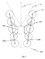
- a rotary wing aircraft 100 is shown with a total of ten rotors 110.
- the rotors 110 are arranged on carrier elements 120a, 120b along both sides of a longitudinal axis L of the aircraft.
- the carrier elements 120a, 120b are connected by bracing elements 130.
- Attached to the bracing members 130 near the center of gravity of the aircraft is a body member 140.
- the body member 140 serves to support the control electronics and power supply (not shown) and any optical and / or sensory elements.
- plastic screws (not shown). These generally have high resistance to tensile and compressive stress and reduced resistance to shear forces. As a result, they can act as predetermined breaking points, while at the same time they do not adversely affect the carrying capacity and stability of the aircraft. Furthermore, plastic screws are lightweight and inexpensive to manufacture.
- the plastic screws are also suitable for the fact that the aircraft can be easily disassembled and rebuilt. On the one hand, this facilitates transport, on the other hand, defective components can be exchanged easily and quickly.
- the carrier elements 120a, 120b are aligned rectilinearly and axially symmetrically on both sides of the longitudinal axis L.
- a free field of view is defined in the front region of the aircraft.
- a free field of view is defined in the front region of the aircraft.
- a range of ⁇ 30 ° to the longitudinal axis L, starting from the body member 140 there are neither rotor nor Carrier element parts or other components of the aircraft in the field of view. It thereby allows an optical or sensory element (not shown) mounted on the fuselage 140 to detect the environment ahead of the aircraft without interference. In particular, this makes it possible to continuously detect the environment of the aircraft from an area above the rotor level, through the rotor level, and to an area below the rotor level without components of the aircraft projecting into the detection area.
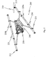
- Fig. 2 shows an oblique view of another embodiment of the invention. For clarity, seven of the eight rotors 210 and motors 215 are not shown.
- Two support elements 220a, 220b are arranged as an open V and connected to each other via X-shaped struts 230.
- the connections between the support elements 220a, 220b and the bracing elements 230 are provided by clamps 231.
- the clamps are less resistant than the carrier elements 220a, 220b and the bracing elements 230 and can therefore serve as predetermined breaking points. In addition, they can be solved quickly and easily, so that the support members 220 a, 220 b can be removed from the bracing elements 230.
- each support member 220a and 220b there are four motor holders 211 equidistant from each other on which are mounted motors 215 which drive the rotors.
- the motors 215 are brushless and sensorless electric motors which are each controlled via an assigned power electronics (not shown). Each individual rotor is associated with an electric motor, so that there is a maximum maneuverability.
- a fuselage element 240 is mounted vibration-damped.
- the body member 240 carries a moveable camera mount 250.
- the configuration is tuned such that the body member 240 is behind and the camera mount 250 is located forward of the aircraft's center of gravity. Both elements together yield Mounting a camera (not shown) on the camera mount a neutral center of gravity, so that when a hover of the aircraft all rotors provide the same thrust.
- the camera mount 250 is pivotable about ⁇ 120 ° with respect to a horizontal plane of the aircraft and ⁇ 30 ° with respect to a vertical plane of the aircraft such that a camera (not shown) pivots above, in front of and below the aircraft by simply pivoting can record.
- the pivoting also roll and pitching movements of the aircraft, as caused for example by acceleration and turning flight can be actively compensated.
- the support elements 220a, 220b are hollow bodies with a diameter which allows the power electronics to be accommodated to drive the motors 215.
- the cables (not shown) for power supply and control of the individual components, starting from the body element 240, are guided through the cable openings 221 into the carrier elements 220a, 220b and subsequently within the latter.
- plugs are provided for disconnecting the cable connection. So that can be done in Fig. 2 shown system can be disassembled in a few simple steps in three handy parts.
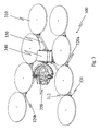
- Fig. 3 shows an oblique view of yet another embodiment of the invention.
- the aircraft includes two support members 320a, 320b, which are arranged as an open V.
- the support elements 320a, 320b are connected to one another via X-shaped strut elements 330.
- Each support member 320a and 320b is formed of a pair of hollow bodies, respectively. Between each pair of hollow bodies a plurality of short connecting webs 312 are mounted, some of which at the same time as motor mounts (not shown) or to Connection 331 of the respective carrier element 320a, 320b serve with the bracing elements 330.
- the node of the X-shaped bracing elements 330 lies on the longitudinal axis behind the spatial center of the aircraft 300.
- a torso element 340 is mounted vibration-damped.
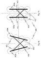
- Fig. 4a and 4b illustrate the mechanism of folding according to a preferred embodiment of the invention.
- Fig. 4a shows the unfolded state in which the aircraft 400 is operated.
- Fig. 4b shows the collapsed state in which the aircraft 400 is transported.
- the rear (more closely connected) connections 432 between the carrier element 420a, 420b and X-shaped bracing member 430 are designed to be rotatable and the front (further apart) connections 431 detachably formed.
- the front connections 431 are released and the support elements 420a, 420b then inwardly around the rear connections 432, ie towards each other, in the in Fig. 4b shown folded state turned.
- the support members 420a, 420b are arranged close to each other in parallel.
- the front arms of the bracing member 430 are retracted telescopically and thus shortened.
- the bracing member 430 is reconnected to the support members 420a, 420b elsewhere via the front links 431. In this in Fig. 4b shown final configuration, the entire aircraft can be transported firmly mounted in one piece.
- the support members may be permanently connected or integrally formed with the fuselage and / or strut members.
- an aircraft according to the invention has equivalent or nearly equivalent flight characteristics with respect to each of the three axes longitudinal axis, transverse axis and vertical axis, so that the longitudinal axis is only the preferred, not the exclusive, direction of forward motion of the aircraft is.
- a rotary wing aircraft according to the invention is used for a manned flight, so that the advantageous properties mentioned herein benefit the persons located thereon. It is therefore intended that the specification and examples be considered as exemplary only, with the scope of the invention being defined by the appended claims.
Landscapes
- Engineering & Computer Science (AREA)
- Mechanical Engineering (AREA)
- Remote Sensing (AREA)
- Aviation & Aerospace Engineering (AREA)
- Accessories Of Cameras (AREA)
- Tires In General (AREA)
- Toys (AREA)
- Gyroscopes (AREA)
Claims (9)
- Giravion (100) comprenant au moins quatre rotors (110) disposés sur des éléments porteurs (120a, 120b),
dans lequel les rotors (110) et les éléments porteurs (120a, 120b) sont ainsi disposés que le long d'un axe longitudinal (L) du giravion (100), un champ visuel libre (S) est défini entre au moins deux rotors d'extrémité, et les éléments porteurs (120a, 120b) mettent en place une liaison en ligne droite entre les rotors, respectivement sur un côté de l'axe longitudinal (L),
caractérisé en ce que les éléments porteurs (120a, 120b) sont disposés symétriquement en V par rapport à l'axe longitudinal. - Giravion selon la revendication 1, caractérisé en ce que les éléments porteurs (120a, 120b) s'étendent essentiellement en ligne droite des deux côtés de l'axe longitudinal (L).
- Giravion selon la revendication 1 ou 2, caractérisé en ce que le champ visuel libre (S) partant du centre de gravité de l'aéronef, présente un allongement par rapport à l'axe longitudinal de plus de ± 15° tant dans le plan horizontal que vertical.
- Giravion selon l'une des revendications précédentes, caractérisé en ce que le giravion comprend en outre au moins un élément de contrefort (130) pour soutenir les éléments porteurs (120a, 120b).
- Giravion selon la revendication 4, caractérisé en ce que l'au moins un élément de contrefort (130) a la forme d'un X.
- Giravion selon la revendication 4 ou 5, caractérisé en ce que les liaisons entre l'au moins un élément de contrefort (130) et les éléments porteurs (120a, 120b) sont conçues en étant séparables et/ou rotatives.
- Giravion selon l'une des revendications précédentes, comprenant en outre un élément de carlingue (140) avec au moins une fixation pour recevoir au moins un élément optique et/ou de détection.
- Giravion selon la revendication 7, caractérisé en ce que l'au moins une fixation est disposée en étant réglable à proximité du centre de gravité du giravion.
- Emploi d'un giravion selon la revendication 7 ou 8, pour des détections environnementales par des éléments optiques et/ou de détection.
Applications Claiming Priority (2)
| Application Number | Priority Date | Filing Date | Title |
|---|---|---|---|
| DE102008014853A DE102008014853B4 (de) | 2008-03-18 | 2008-03-18 | Drehflügelfluggerät |
| PCT/EP2009/001965 WO2009115300A1 (fr) | 2008-03-18 | 2009-03-17 | Aéronef à voilure tournante |
Publications (2)
| Publication Number | Publication Date |
|---|---|
| EP2254792A1 EP2254792A1 (fr) | 2010-12-01 |
| EP2254792B1 true EP2254792B1 (fr) | 2014-07-16 |
Family
ID=40716941
Family Applications (1)
| Application Number | Title | Priority Date | Filing Date |
|---|---|---|---|
| EP09721874.7A Not-in-force EP2254792B1 (fr) | 2008-03-18 | 2009-03-17 | Aéronef à voilure tournante |
Country Status (8)
| Country | Link |
|---|---|
| US (1) | US9051050B2 (fr) |
| EP (1) | EP2254792B1 (fr) |
| JP (1) | JP5485975B2 (fr) |
| CN (1) | CN101977812B (fr) |
| CA (1) | CA2717810C (fr) |
| DE (1) | DE102008014853B4 (fr) |
| ES (1) | ES2502523T3 (fr) |
| WO (1) | WO2009115300A1 (fr) |
Families Citing this family (86)
| Publication number | Priority date | Publication date | Assignee | Title |
|---|---|---|---|---|
| DE102008014853B4 (de) * | 2008-03-18 | 2010-11-18 | Ascending Technologies Gmbh | Drehflügelfluggerät |
| DE102010040770B4 (de) | 2010-09-14 | 2012-08-23 | Ascending Technologies Gmbh | Verfahren zur Verbesserung der Flugeigenschaften eines Multikopters in Ausfallsituationen |
| WO2013105926A1 (fr) * | 2011-03-22 | 2013-07-18 | Aerovironment Inc. | Aéronef réversible |
| JP2014528382A (ja) * | 2011-10-17 | 2014-10-27 | ユー ティアン | 固定翼および電動マルチローターを組み合わせた航空機 |
| DE102011119590A1 (de) * | 2011-11-29 | 2013-05-29 | Aibotix GmbH | Fernsteuerbare Flugplattform |
| WO2013124300A1 (fr) * | 2012-02-22 | 2013-08-29 | E-Volo Gmbh | Aéronef |
| DE102012202698B4 (de) * | 2012-02-22 | 2023-06-07 | Volocopter Gmbh | Fluggerät |
| SI24055A (sl) | 2012-04-16 | 2013-10-30 | Airmamics Napredni Mehatronski Sistemi D.O.O. | Krmilni sistem stabilizacijske glave za letečo ali stacionarno platformo |
| DE102012104783B4 (de) | 2012-06-01 | 2019-12-24 | Quantum-Systems Gmbh | Fluggerät, bevorzugt UAV, Drohne und/oder UAS |
| KR102009277B1 (ko) * | 2012-10-22 | 2019-08-09 | 엘지전자 주식회사 | 히트펌프를 구비한 의류처리장치 및 그 제어방법 |
| CN102999049B (zh) * | 2012-11-09 | 2016-04-27 | 国家电网公司 | 一种无线遥控架空线路巡检飞行器 |
| CN103921933A (zh) | 2013-01-10 | 2014-07-16 | 深圳市大疆创新科技有限公司 | 飞行器变形结构及微型飞行器 |
| US9513371B2 (en) | 2013-02-28 | 2016-12-06 | Identified Technologies Corporation | Ground survey and obstacle detection system |
| US20140263822A1 (en) * | 2013-03-18 | 2014-09-18 | Chester Charles Malveaux | Vertical take off and landing autonomous/semiautonomous/remote controlled aerial agricultural sensor platform |
| US9382003B2 (en) | 2013-03-24 | 2016-07-05 | Bee Robotics Corporation | Aerial farm robot system for crop dusting, planting, fertilizing and other field jobs |
| CA2815885C (fr) * | 2013-05-15 | 2018-05-15 | Draganfly Innovations Inc. | Aeronef a voilure tournante non habite compact |
| DE102013107654A1 (de) * | 2013-07-18 | 2015-01-22 | OIC-GmbH | Fluggerät zum Befördern von einem oder mehreren Aufnahmegeräten durch die Luft |
| USD710454S1 (en) | 2013-08-15 | 2014-08-05 | Traxxas Lp | Canopy for a quadrotor model helicopter |
| CN108465254B (zh) | 2013-08-15 | 2021-01-08 | 特拉克赛卡斯公司 | 具有集成光管支撑构件的旋翼飞机 |
| USD710453S1 (en) | 2013-08-15 | 2014-08-05 | Traxxas Lp | Quadrotor model helicopter airframe |
| USD710452S1 (en) | 2013-08-15 | 2014-08-05 | Traxxas Lp | Quadrotor model helicopter |
| DE102013225304B4 (de) | 2013-12-09 | 2021-06-24 | Meteomatics Gmbh | Fluggerät |
| TWI508763B (zh) * | 2014-01-08 | 2015-11-21 | Univ Nat Formosa | Foldable Shaped six rotorcraft |
| US9862487B2 (en) | 2014-05-23 | 2018-01-09 | Aibotix GmbH | Remote-controlled platform shaped aircraft |
| DE102014211050B4 (de) * | 2014-06-10 | 2020-10-08 | Fraunhofer-Gesellschaft zur Förderung der angewandten Forschung e.V. | Bildgebende Vorrichtung mit flugfähiger Tragevorrichtung |
| DE202014009436U1 (de) | 2014-06-17 | 2015-01-08 | Flairics Gmbh & Co. Kg | Modularer Multikopter |
| EP3509172B1 (fr) | 2014-06-26 | 2022-03-16 | SZ DJI Technology Co., Ltd. | Véhicule aérien et ensemble de protection de ligne de signal associé |
| IL233942B (en) | 2014-08-04 | 2020-01-30 | Israel Aerospace Ind Ltd | Assembly of the drive system |
| JP6425466B2 (ja) * | 2014-09-01 | 2018-11-21 | 国立大学法人 東京大学 | 飛行装置 |
| DE102014113191A1 (de) * | 2014-09-12 | 2016-03-17 | Hochschule für Angewandte Wissenschaften Hamburg (HAW Hamburg) | Dezentrale redundante Architektur für ein unbemanntes Luftfahrzeug zur vereinfachten Integration von Sensorsystemen |
| US9754496B2 (en) | 2014-09-30 | 2017-09-05 | Elwha Llc | System and method for management of airspace for unmanned aircraft |
| CN104229131A (zh) * | 2014-10-13 | 2014-12-24 | 新誉集团有限公司 | V型八旋翼航拍飞行器 |
| US20160272310A1 (en) * | 2014-12-04 | 2016-09-22 | Elwha Llc | Reconfigurable unmanned aircraft system |
| US9919797B2 (en) * | 2014-12-04 | 2018-03-20 | Elwha Llc | System and method for operation and management of reconfigurable unmanned aircraft |
| US20160214713A1 (en) * | 2014-12-19 | 2016-07-28 | Brandon Cragg | Unmanned aerial vehicle with lights, audio and video |
| US9836053B2 (en) | 2015-01-04 | 2017-12-05 | Zero Zero Robotics Inc. | System and method for automated aerial system operation |
| CN105235891B (zh) * | 2015-01-04 | 2020-02-14 | 北京零零无限科技有限公司 | 一种可折叠的无人机 |
| US10358214B2 (en) | 2015-01-04 | 2019-07-23 | Hangzhou Zero Zro Technology Co., Ltd. | Aerial vehicle and method of operation |
| US10126745B2 (en) | 2015-01-04 | 2018-11-13 | Hangzhou Zero Zero Technology Co., Ltd. | System and method for automated aerial system operation |
| WO2016112124A2 (fr) * | 2015-01-08 | 2016-07-14 | Vantage Robotics, Llc | Véhicule aérien sans pilote à protection d'hélice et capacité de survie aux impacts élevée |
| JP6536042B2 (ja) * | 2015-01-23 | 2019-07-03 | 株式会社Ihi | 飛行体 |
| FR3032687B1 (fr) * | 2015-02-16 | 2018-10-12 | Hutchinson | Aerodyne vtol a soufflante(s) axiale(s) porteuse(s) |
| EP3892535A1 (fr) * | 2015-06-01 | 2021-10-13 | SZ DJI Technology Co., Ltd. | Bras segmenté pour l'unité de propulsion d'un véhicule aérien sans pilote |
| US9764829B1 (en) * | 2015-06-09 | 2017-09-19 | Amazon Technologies, Inc. | Multirotor aircraft with enhanced yaw control |
| CN205989812U (zh) | 2015-06-25 | 2017-03-01 | 瑞德利斯技术公司 | 多旋翼无人机 |
| US9878787B2 (en) | 2015-07-15 | 2018-01-30 | Elwha Llc | System and method for operating unmanned aircraft |
| US9922282B2 (en) | 2015-07-21 | 2018-03-20 | Limitless Computing, Inc. | Automated readiness evaluation system (ARES) for use with an unmanned aircraft system (UAS) |
| EP3202662B1 (fr) * | 2015-07-31 | 2020-06-24 | Guangzhou Xaircraft Technology Co., Ltd. | Véhicule aérien sans pilote |
| CN105468029B (zh) * | 2015-09-23 | 2018-03-02 | 杨珊珊 | 一种无人机航拍装置及方法 |
| USD827724S1 (en) | 2015-09-28 | 2018-09-04 | Traxxas Lp | Set of supporting arms for a quadrotor model helicopter |
| USD827723S1 (en) | 2015-09-28 | 2018-09-04 | Traxxas Lp | Quadrotor model helicopter |
| DE102015119065B4 (de) * | 2015-11-06 | 2025-09-18 | Spherie Gmbh | Flügelloses Fluggerät |
| US10435144B2 (en) | 2016-04-24 | 2019-10-08 | Hangzhou Zero Zero Technology Co., Ltd. | Aerial system propulsion assembly and method of use |
| US9840327B1 (en) | 2016-04-29 | 2017-12-12 | Rfrank Llc | Vertical takeoff and landing (VTOL) aircraft and system |
| RU2627220C1 (ru) * | 2016-07-26 | 2017-08-04 | Общество с ограниченной ответственностью "АвиаНовации" | Летательный аппарат вертикального взлета и посадки |
| DE102016010873A1 (de) | 2016-09-02 | 2018-03-08 | Mario Hintze | Multicopter-Tragwerk in Leichtbauweise |
| US11141673B1 (en) | 2016-09-28 | 2021-10-12 | Traxxas Lp | Model rotorcraft with light pipe support members |
| US20180170510A1 (en) * | 2016-12-15 | 2018-06-21 | Raytheon Company | Tube launched hybrid multirotor methods and apparatus for system |
| USD870638S1 (en) * | 2017-05-19 | 2019-12-24 | Hg Robotics Company Limited | Unmanned aerial vehicle |
| USD851540S1 (en) | 2017-06-07 | 2019-06-18 | MerchSource, LLC | Drone |
| USD902078S1 (en) | 2017-06-07 | 2020-11-17 | MerchSource, LLC | Drone |
| US10364029B2 (en) * | 2017-06-08 | 2019-07-30 | Yongbiao Liu | Drone for agriculture |
| USD825380S1 (en) | 2017-06-27 | 2018-08-14 | MerchSource, LLC | Drone for kids |
| USD825669S1 (en) | 2017-07-10 | 2018-08-14 | MerchSource, LLC | Drone car |
| US10745102B2 (en) * | 2017-07-17 | 2020-08-18 | Griff Aviation As | Swingable arm mount for an aerial vehicle having a lift generating means, and an aerial vehicle, advantageously a multicopter with a swingable arm mount |
| USD852091S1 (en) | 2017-07-20 | 2019-06-25 | MerchSource, LLC | Drone |
| CN109383773A (zh) * | 2017-08-02 | 2019-02-26 | 胡春生 | 一种可垂直起降的固定翼飞行器 |
| USD862285S1 (en) | 2017-08-25 | 2019-10-08 | MerchSource, LLC | Drone |
| USD846445S1 (en) | 2017-09-15 | 2019-04-23 | MerchSource, LLC | Drone |
| DE112018006375A5 (de) * | 2017-12-15 | 2020-10-08 | Innotec Lightweight Engineering & Polymer Technology Gmbh | Start- und Landestation |
| US10836508B2 (en) | 2018-02-16 | 2020-11-17 | Jeffrey Paul Overall | Camera drone |
| JP7025954B2 (ja) * | 2018-02-22 | 2022-02-25 | 訓範 津田 | 無人航空機 |
| DE102018123348A1 (de) * | 2018-09-21 | 2020-03-26 | Quantum-Systems Gmbh | Fluggerätsystem, insbesondere unbemanntes Fluggerätsystem, Fluggeräterumpf und Antriebsmoduleinheit, insbesondere für ein unbemanntes Fluggerät |
| CN109494628B (zh) * | 2018-11-24 | 2024-02-27 | 王丽红 | 一种电力放线多旋翼无人机及电力放线方法 |
| HRP20220528T1 (hr) * | 2018-11-30 | 2022-05-27 | UMILES Urban Air Mobility, S.L. | Zračno vozilo s nepovezanim stupnjevima slobode |
| AU2020205823A1 (en) | 2019-01-10 | 2021-07-29 | Arrowtec Gmbh | Automatic aerial shipping system |
| CN113677187A (zh) * | 2019-03-28 | 2021-11-19 | 渥美不动产有限公司 | 具备圆柱形旋转体的作业装置 |
| CN114340998B (zh) * | 2019-10-09 | 2024-12-27 | 小鹰公司 | 用于不同飞行模式的混合功率系统 |
| JP7417244B2 (ja) * | 2019-10-16 | 2024-01-18 | 株式会社エアロネクスト | 飛行体 |
| US20210214067A1 (en) * | 2020-01-13 | 2021-07-15 | Skydio, Inc. | Autonomous Unmanned Aerial Vehicle With Folding Collapsible Arms |
| DE102020200746B4 (de) | 2020-01-22 | 2022-03-31 | Volkswagen Aktiengesellschaft | Multicopter und Verfahren zum Betreiben eines Multicopters |
| WO2022125132A1 (fr) * | 2020-12-11 | 2022-06-16 | California Institute Of Technology | Systèmes et procédés de commande de vol sur un aéronef à rotors multiples |
| WO2022159951A1 (fr) | 2021-01-19 | 2022-07-28 | California Institute Of Technology | Systèmes et procédés de réduction de couple de lacet sur un aéronef à rotors multiples |
| US12269581B2 (en) | 2021-03-17 | 2025-04-08 | TooFon, Inc. | Systems and methods for efficient cruise and hover in VTOL |
| WO2024021135A1 (fr) * | 2022-07-29 | 2024-02-01 | 深圳市大疆创新科技有限公司 | Aéronef |
| EP4568895A1 (fr) * | 2022-08-09 | 2025-06-18 | Pete Bitar | Dispositif de livraison par drone compact et léger appelé système de drone à réacteur électrique arcspear ayant un système de propulsion à air canalisé électrique et étant relativement difficile à suivre en vol |
Citations (2)
| Publication number | Priority date | Publication date | Assignee | Title |
|---|---|---|---|---|
| US2987272A (en) * | 1959-04-29 | 1961-06-06 | Curtiss Wright Corp | Aircraft with a tiltable rotor system |
| US6260796B1 (en) * | 1997-03-04 | 2001-07-17 | Wallace Neil Klingensmith | Multi-thrustered hover craft |
Family Cites Families (29)
| Publication number | Priority date | Publication date | Assignee | Title |
|---|---|---|---|---|
| FR420315A (fr) * | 1909-11-19 | 1911-01-27 | Jean Jacques Elie Farcot | Perfectionnements aux appareils d'aviation |
| US1573563A (en) * | 1923-03-28 | 1926-02-16 | Edward Y Moore | Helicopter |
| US1749471A (en) * | 1924-03-29 | 1930-03-04 | Bothezat George De | Helicopter |
| US1892036A (en) * | 1931-04-17 | 1932-12-27 | Campens Denis Remy | Helicopter |
| US2651480A (en) * | 1945-08-01 | 1953-09-08 | Autogiro Co Of America | Multiple rotor helicopter |
| US2571566A (en) * | 1949-01-04 | 1951-10-16 | John A Green | Control system for multiple rotor helicopters |
| AT203876B (de) * | 1957-04-05 | 1959-06-10 | Josef Moestl | Hubschrauber |
| US3185410A (en) * | 1963-10-21 | 1965-05-25 | Raymond C Smart | Vertical lift aircraft |
| US4032084A (en) * | 1976-03-11 | 1977-06-28 | Black John O | Helicopter type aircraft with ground effect structure |
| US4923144A (en) * | 1987-09-03 | 1990-05-08 | Karl Eickmann | Aircraft with pivotable wing and arrestable propellers |
| JPH0482584A (ja) * | 1990-07-26 | 1992-03-16 | Hiroshi Kuno | 遠隔操縦による浮遊玩具 |
| US5178344A (en) * | 1991-09-13 | 1993-01-12 | Vaclav Dlouhy | VTOL aircraft |
| US5589901A (en) * | 1995-05-15 | 1996-12-31 | Means; Kevin P. | Apparatus and method for synchronizing search and surveillance devices |
| DE19745492B4 (de) * | 1997-10-15 | 2005-06-09 | Wobben, Aloys, Dipl.-Ing. | Senkrecht startendes Flugzeug |
| RU2232105C2 (ru) * | 2002-04-16 | 2004-07-10 | ООО "Мидера-К" | Аэродинамический подъемно-тянущий движитель |
| CN1583510A (zh) * | 2003-08-19 | 2005-02-23 | 陈树声 | 复合结构体高性能水陆两用直升机 |
| US7472863B2 (en) * | 2004-07-09 | 2009-01-06 | Steve Pak | Sky hopper |
| DE102005010336B4 (de) * | 2004-11-06 | 2007-09-06 | Dolch, Stefan, Dipl.-Ing. (FH) | Drehzahlgesteuerter Hubschrauber |
| DE102004063205B3 (de) * | 2004-12-23 | 2006-05-04 | Julian Kuntz | Fluggerät mit verbesserter Beweglichkeit am Boden |
| DE102005022706A1 (de) * | 2005-05-18 | 2006-11-23 | Dolch, Stefan, Dipl.-Ing. (FH) | Hubschrauber mit einer Kamera |
| DE102005022705A1 (de) * | 2005-05-18 | 2006-11-23 | Dolch, Stefan, Dipl.-Ing. (FH) | Hubschrauber mit Kamera |
| DE102005061741A1 (de) * | 2005-12-21 | 2007-07-05 | Michael Achtelik | Vierrotoriger Helikopter mit kollektiver Blattverstellung |
| DE102006021182B4 (de) * | 2006-05-06 | 2012-10-31 | Zoltán Rácz | Fluggerät mit vier Hubrotoren und drei Drehachsen als universelle Flugplattform |
| CN100391790C (zh) * | 2006-05-18 | 2008-06-04 | 战强 | 多旋翼飞行器 |
| EP1901153A1 (fr) * | 2006-09-12 | 2008-03-19 | OFFIS e.V. | Système de contrôle pour un hélicoptère sans pilote avec 4 rotors |
| CN200964040Y (zh) * | 2006-11-07 | 2007-10-24 | 北京航空航天大学 | 一种多功能飞行器 |
| DE202006013909U1 (de) * | 2006-11-17 | 2007-02-22 | Bieberich, Peter | Modular aufgebautes Fluggerät, insbesondere Quadrocopter |
| US8453962B2 (en) * | 2007-02-16 | 2013-06-04 | Donald Orval Shaw | Modular flying vehicle |
| DE102008014853B4 (de) * | 2008-03-18 | 2010-11-18 | Ascending Technologies Gmbh | Drehflügelfluggerät |
-
2008
- 2008-03-18 DE DE102008014853A patent/DE102008014853B4/de not_active Expired - Fee Related
-
2009
- 2009-03-17 EP EP09721874.7A patent/EP2254792B1/fr not_active Not-in-force
- 2009-03-17 WO PCT/EP2009/001965 patent/WO2009115300A1/fr not_active Ceased
- 2009-03-17 CN CN200980109713.9A patent/CN101977812B/zh not_active Expired - Fee Related
- 2009-03-17 CA CA2717810A patent/CA2717810C/fr not_active Expired - Fee Related
- 2009-03-17 JP JP2011500112A patent/JP5485975B2/ja not_active Expired - Fee Related
- 2009-03-17 ES ES09721874.7T patent/ES2502523T3/es active Active
- 2009-03-17 US US12/922,895 patent/US9051050B2/en not_active Expired - Fee Related
Patent Citations (2)
| Publication number | Priority date | Publication date | Assignee | Title |
|---|---|---|---|---|
| US2987272A (en) * | 1959-04-29 | 1961-06-06 | Curtiss Wright Corp | Aircraft with a tiltable rotor system |
| US6260796B1 (en) * | 1997-03-04 | 2001-07-17 | Wallace Neil Klingensmith | Multi-thrustered hover craft |
Also Published As
| Publication number | Publication date |
|---|---|
| WO2009115300A1 (fr) | 2009-09-24 |
| CA2717810C (fr) | 2015-05-12 |
| DE102008014853B4 (de) | 2010-11-18 |
| CN101977812B (zh) | 2014-03-26 |
| US20110017865A1 (en) | 2011-01-27 |
| EP2254792A1 (fr) | 2010-12-01 |
| CN101977812A (zh) | 2011-02-16 |
| DE102008014853A1 (de) | 2009-10-08 |
| CA2717810A1 (fr) | 2009-09-24 |
| ES2502523T3 (es) | 2014-10-03 |
| JP5485975B2 (ja) | 2014-05-07 |
| JP2011514287A (ja) | 2011-05-06 |
| US9051050B2 (en) | 2015-06-09 |
Similar Documents
| Publication | Publication Date | Title |
|---|---|---|
| EP2254792B1 (fr) | Aéronef à voilure tournante | |
| EP2035276B1 (fr) | Aéronef | |
| DE69103363T2 (de) | Drehbarer Balken um Kameras für stereophotogrammetrische Aufnahmen auf einem Hubschrauber zu montieren. | |
| EP2233393B1 (fr) | Système de verrouillage | |
| EP1943143B1 (fr) | Avion | |
| EP2327612B1 (fr) | Véhicule pour l'inspection autonome d'espaces intérieurs difficilement accessibles | |
| DE112009001649T5 (de) | Rotierendes Fluggerät mit einem an der Unterseite montierten verstellbaren Blatt | |
| DE102005046155B4 (de) | Hubschrauber mit koaxialen Hauptrotoren | |
| DE102013021884B4 (de) | Unbemanntes schwebefähiges Fluggerät | |
| DE102007054126A1 (de) | Unbemanntes Banner-tragendes Fluggerät und Verfahren zum Lufttransport eines Darstellungsobjekts | |
| EP2826711A1 (fr) | Aéronef destiné au transport d'un ou plusieurs appareils d'enregistrement dans les airs | |
| AT517539B1 (de) | VTOL-Luftfahrzeug mit bewegbarer Masse zur Steuerung | |
| DE602004002891T2 (de) | Vorrichtung für die Hinteraufhängung eines Triebwerkes an einem Luftfahrzeug | |
| EP2733070A2 (fr) | Aéronef | |
| DE3873176T2 (de) | Rotoranordnung eines drehfluegelflugzeuges. | |
| DE102005014949A1 (de) | Hubschrauber mit variablen Abmessungen | |
| DE202014009436U1 (de) | Modularer Multikopter | |
| DE102013011378A1 (de) | Rahmen für einen Flugkörper | |
| DE102008038434A1 (de) | Hubschrauber mit quer angeordnetem Doppelpropeller, der in vier Frequenzbereichen bedienbar ist | |
| EP3858559A1 (fr) | Plateforme de dressage, système de capteurs, avion et procédé de fonctionnement d'une plateforme de dressage | |
| DE3030375A1 (de) | Ferngesteuerter hubschrauber | |
| DE60314424T2 (de) | Mechanismus zum eindeutigen Verbinden einer verschiebbaren und ausrichtbaren Plattform mit einer Tragkonstruktion unter Verwendung von Gelenkarmen | |
| EP3508421A1 (fr) | Mécanisme d'entraînement d'hélicoptère et procédé de fonctionnement d'un mécanisme d'entraînement d'hélicoptère | |
| DE102023129578A1 (de) | Luftfahrzeug und verfahren |
Legal Events
| Date | Code | Title | Description |
|---|---|---|---|
| PUAI | Public reference made under article 153(3) epc to a published international application that has entered the european phase |
Free format text: ORIGINAL CODE: 0009012 |
|
| 17P | Request for examination filed |
Effective date: 20101014 |
|
| AK | Designated contracting states |
Kind code of ref document: A1 Designated state(s): AT BE BG CH CY CZ DE DK EE ES FI FR GB GR HR HU IE IS IT LI LT LU LV MC MK MT NL NO PL PT RO SE SI SK TR |
|
| AX | Request for extension of the european patent |
Extension state: AL BA RS |
|
| DAX | Request for extension of the european patent (deleted) | ||
| 17Q | First examination report despatched |
Effective date: 20130628 |
|
| REG | Reference to a national code |
Ref country code: DE Ref legal event code: R079 Ref document number: 502009009654 Country of ref document: DE Free format text: PREVIOUS MAIN CLASS: B64C0027080000 Ipc: B64C0039020000 |
|
| RIC1 | Information provided on ipc code assigned before grant |
Ipc: B64C 39/02 20060101AFI20131106BHEP Ipc: B64C 27/08 20060101ALI20131106BHEP Ipc: B64D 47/08 20060101ALI20131106BHEP |
|
| GRAP | Despatch of communication of intention to grant a patent |
Free format text: ORIGINAL CODE: EPIDOSNIGR1 |
|
| INTG | Intention to grant announced |
Effective date: 20140203 |
|
| GRAS | Grant fee paid |
Free format text: ORIGINAL CODE: EPIDOSNIGR3 |
|
| GRAA | (expected) grant |
Free format text: ORIGINAL CODE: 0009210 |
|
| AK | Designated contracting states |
Kind code of ref document: B1 Designated state(s): AT BE BG CH CY CZ DE DK EE ES FI FR GB GR HR HU IE IS IT LI LT LU LV MC MK MT NL NO PL PT RO SE SI SK TR |
|
| REG | Reference to a national code |
Ref country code: GB Ref legal event code: FG4D Free format text: NOT ENGLISH |
|
| REG | Reference to a national code |
Ref country code: CH Ref legal event code: EP |
|
| REG | Reference to a national code |
Ref country code: IE Ref legal event code: FG4D Free format text: LANGUAGE OF EP DOCUMENT: GERMAN |
|
| REG | Reference to a national code |
Ref country code: AT Ref legal event code: REF Ref document number: 677445 Country of ref document: AT Kind code of ref document: T Effective date: 20140815 |
|
| REG | Reference to a national code |
Ref country code: DE Ref legal event code: R096 Ref document number: 502009009654 Country of ref document: DE Effective date: 20140828 |
|
| REG | Reference to a national code |
Ref country code: CH Ref legal event code: NV Representative=s name: SCHMAUDER AND PARTNER AG PATENT- UND MARKENANW, CH |
|
| REG | Reference to a national code |
Ref country code: ES Ref legal event code: FG2A Ref document number: 2502523 Country of ref document: ES Kind code of ref document: T3 Effective date: 20141003 |
|
| REG | Reference to a national code |
Ref country code: NL Ref legal event code: VDEP Effective date: 20140716 |
|
| REG | Reference to a national code |
Ref country code: LT Ref legal event code: MG4D |
|
| PG25 | Lapsed in a contracting state [announced via postgrant information from national office to epo] |
Ref country code: BG Free format text: LAPSE BECAUSE OF FAILURE TO SUBMIT A TRANSLATION OF THE DESCRIPTION OR TO PAY THE FEE WITHIN THE PRESCRIBED TIME-LIMIT Effective date: 20141016 Ref country code: LT Free format text: LAPSE BECAUSE OF FAILURE TO SUBMIT A TRANSLATION OF THE DESCRIPTION OR TO PAY THE FEE WITHIN THE PRESCRIBED TIME-LIMIT Effective date: 20140716 Ref country code: PT Free format text: LAPSE BECAUSE OF FAILURE TO SUBMIT A TRANSLATION OF THE DESCRIPTION OR TO PAY THE FEE WITHIN THE PRESCRIBED TIME-LIMIT Effective date: 20141117 Ref country code: SE Free format text: LAPSE BECAUSE OF FAILURE TO SUBMIT A TRANSLATION OF THE DESCRIPTION OR TO PAY THE FEE WITHIN THE PRESCRIBED TIME-LIMIT Effective date: 20140716 Ref country code: GR Free format text: LAPSE BECAUSE OF FAILURE TO SUBMIT A TRANSLATION OF THE DESCRIPTION OR TO PAY THE FEE WITHIN THE PRESCRIBED TIME-LIMIT Effective date: 20141017 Ref country code: NO Free format text: LAPSE BECAUSE OF FAILURE TO SUBMIT A TRANSLATION OF THE DESCRIPTION OR TO PAY THE FEE WITHIN THE PRESCRIBED TIME-LIMIT Effective date: 20141016 Ref country code: FI Free format text: LAPSE BECAUSE OF FAILURE TO SUBMIT A TRANSLATION OF THE DESCRIPTION OR TO PAY THE FEE WITHIN THE PRESCRIBED TIME-LIMIT Effective date: 20140716 |
|
| PG25 | Lapsed in a contracting state [announced via postgrant information from national office to epo] |
Ref country code: LV Free format text: LAPSE BECAUSE OF FAILURE TO SUBMIT A TRANSLATION OF THE DESCRIPTION OR TO PAY THE FEE WITHIN THE PRESCRIBED TIME-LIMIT Effective date: 20140716 Ref country code: IS Free format text: LAPSE BECAUSE OF FAILURE TO SUBMIT A TRANSLATION OF THE DESCRIPTION OR TO PAY THE FEE WITHIN THE PRESCRIBED TIME-LIMIT Effective date: 20141116 Ref country code: PL Free format text: LAPSE BECAUSE OF FAILURE TO SUBMIT A TRANSLATION OF THE DESCRIPTION OR TO PAY THE FEE WITHIN THE PRESCRIBED TIME-LIMIT Effective date: 20140716 Ref country code: CY Free format text: LAPSE BECAUSE OF FAILURE TO SUBMIT A TRANSLATION OF THE DESCRIPTION OR TO PAY THE FEE WITHIN THE PRESCRIBED TIME-LIMIT Effective date: 20140716 Ref country code: NL Free format text: LAPSE BECAUSE OF FAILURE TO SUBMIT A TRANSLATION OF THE DESCRIPTION OR TO PAY THE FEE WITHIN THE PRESCRIBED TIME-LIMIT Effective date: 20140716 |
|
| REG | Reference to a national code |
Ref country code: FR Ref legal event code: PLFP Year of fee payment: 7 |
|
| REG | Reference to a national code |
Ref country code: DE Ref legal event code: R097 Ref document number: 502009009654 Country of ref document: DE |
|
| PG25 | Lapsed in a contracting state [announced via postgrant information from national office to epo] |
Ref country code: DK Free format text: LAPSE BECAUSE OF FAILURE TO SUBMIT A TRANSLATION OF THE DESCRIPTION OR TO PAY THE FEE WITHIN THE PRESCRIBED TIME-LIMIT Effective date: 20140716 Ref country code: SK Free format text: LAPSE BECAUSE OF FAILURE TO SUBMIT A TRANSLATION OF THE DESCRIPTION OR TO PAY THE FEE WITHIN THE PRESCRIBED TIME-LIMIT Effective date: 20140716 Ref country code: IT Free format text: LAPSE BECAUSE OF FAILURE TO SUBMIT A TRANSLATION OF THE DESCRIPTION OR TO PAY THE FEE WITHIN THE PRESCRIBED TIME-LIMIT Effective date: 20140716 Ref country code: RO Free format text: LAPSE BECAUSE OF FAILURE TO SUBMIT A TRANSLATION OF THE DESCRIPTION OR TO PAY THE FEE WITHIN THE PRESCRIBED TIME-LIMIT Effective date: 20140716 Ref country code: CZ Free format text: LAPSE BECAUSE OF FAILURE TO SUBMIT A TRANSLATION OF THE DESCRIPTION OR TO PAY THE FEE WITHIN THE PRESCRIBED TIME-LIMIT Effective date: 20140716 Ref country code: EE Free format text: LAPSE BECAUSE OF FAILURE TO SUBMIT A TRANSLATION OF THE DESCRIPTION OR TO PAY THE FEE WITHIN THE PRESCRIBED TIME-LIMIT Effective date: 20140716 |
|
| PLBE | No opposition filed within time limit |
Free format text: ORIGINAL CODE: 0009261 |
|
| STAA | Information on the status of an ep patent application or granted ep patent |
Free format text: STATUS: NO OPPOSITION FILED WITHIN TIME LIMIT |
|
| 26N | No opposition filed |
Effective date: 20150417 |
|
| PG25 | Lapsed in a contracting state [announced via postgrant information from national office to epo] |
Ref country code: MC Free format text: LAPSE BECAUSE OF FAILURE TO SUBMIT A TRANSLATION OF THE DESCRIPTION OR TO PAY THE FEE WITHIN THE PRESCRIBED TIME-LIMIT Effective date: 20140716 Ref country code: LU Free format text: LAPSE BECAUSE OF FAILURE TO SUBMIT A TRANSLATION OF THE DESCRIPTION OR TO PAY THE FEE WITHIN THE PRESCRIBED TIME-LIMIT Effective date: 20150317 |
|
| PG25 | Lapsed in a contracting state [announced via postgrant information from national office to epo] |
Ref country code: SI Free format text: LAPSE BECAUSE OF FAILURE TO SUBMIT A TRANSLATION OF THE DESCRIPTION OR TO PAY THE FEE WITHIN THE PRESCRIBED TIME-LIMIT Effective date: 20140716 |
|
| REG | Reference to a national code |
Ref country code: FR Ref legal event code: PLFP Year of fee payment: 8 |
|
| PG25 | Lapsed in a contracting state [announced via postgrant information from national office to epo] |
Ref country code: MT Free format text: LAPSE BECAUSE OF FAILURE TO SUBMIT A TRANSLATION OF THE DESCRIPTION OR TO PAY THE FEE WITHIN THE PRESCRIBED TIME-LIMIT Effective date: 20140716 |
|
| REG | Reference to a national code |
Ref country code: FR Ref legal event code: PLFP Year of fee payment: 9 |
|
| PG25 | Lapsed in a contracting state [announced via postgrant information from national office to epo] |
Ref country code: HU Free format text: LAPSE BECAUSE OF FAILURE TO SUBMIT A TRANSLATION OF THE DESCRIPTION OR TO PAY THE FEE WITHIN THE PRESCRIBED TIME-LIMIT; INVALID AB INITIO Effective date: 20090317 |
|
| PG25 | Lapsed in a contracting state [announced via postgrant information from national office to epo] |
Ref country code: HR Free format text: LAPSE BECAUSE OF FAILURE TO SUBMIT A TRANSLATION OF THE DESCRIPTION OR TO PAY THE FEE WITHIN THE PRESCRIBED TIME-LIMIT Effective date: 20140716 Ref country code: BE Free format text: LAPSE BECAUSE OF NON-PAYMENT OF DUE FEES Effective date: 20150331 |
|
| REG | Reference to a national code |
Ref country code: GB Ref legal event code: 732E Free format text: REGISTERED BETWEEN 20170706 AND 20170715 |
|
| PG25 | Lapsed in a contracting state [announced via postgrant information from national office to epo] |
Ref country code: TR Free format text: LAPSE BECAUSE OF FAILURE TO SUBMIT A TRANSLATION OF THE DESCRIPTION OR TO PAY THE FEE WITHIN THE PRESCRIBED TIME-LIMIT Effective date: 20140716 |
|
| REG | Reference to a national code |
Ref country code: AT Ref legal event code: PC Ref document number: 677445 Country of ref document: AT Kind code of ref document: T Owner name: INTEL DEUTSCHLAND GMBH, DE Effective date: 20170822 |
|
| REG | Reference to a national code |
Ref country code: FR Ref legal event code: TP Owner name: INTEL DEUTSCHLAND GMBH, DE Effective date: 20180123 |
|
| REG | Reference to a national code |
Ref country code: FR Ref legal event code: PLFP Year of fee payment: 10 |
|
| PG25 | Lapsed in a contracting state [announced via postgrant information from national office to epo] |
Ref country code: MK Free format text: LAPSE BECAUSE OF FAILURE TO SUBMIT A TRANSLATION OF THE DESCRIPTION OR TO PAY THE FEE WITHIN THE PRESCRIBED TIME-LIMIT Effective date: 20140716 |
|
| PGFP | Annual fee paid to national office [announced via postgrant information from national office to epo] |
Ref country code: GB Payment date: 20190313 Year of fee payment: 11 Ref country code: FR Payment date: 20190305 Year of fee payment: 11 |
|
| PGFP | Annual fee paid to national office [announced via postgrant information from national office to epo] |
Ref country code: AT Payment date: 20190226 Year of fee payment: 11 |
|
| PGFP | Annual fee paid to national office [announced via postgrant information from national office to epo] |
Ref country code: ES Payment date: 20190401 Year of fee payment: 11 |
|
| PGFP | Annual fee paid to national office [announced via postgrant information from national office to epo] |
Ref country code: DE Payment date: 20200303 Year of fee payment: 12 Ref country code: IE Payment date: 20200309 Year of fee payment: 12 |
|
| REG | Reference to a national code |
Ref country code: CH Ref legal event code: PL |
|
| REG | Reference to a national code |
Ref country code: AT Ref legal event code: MM01 Ref document number: 677445 Country of ref document: AT Kind code of ref document: T Effective date: 20200317 |
|
| PG25 | Lapsed in a contracting state [announced via postgrant information from national office to epo] |
Ref country code: LI Free format text: LAPSE BECAUSE OF NON-PAYMENT OF DUE FEES Effective date: 20200331 Ref country code: FR Free format text: LAPSE BECAUSE OF NON-PAYMENT OF DUE FEES Effective date: 20200331 Ref country code: CH Free format text: LAPSE BECAUSE OF NON-PAYMENT OF DUE FEES Effective date: 20200331 Ref country code: AT Free format text: LAPSE BECAUSE OF NON-PAYMENT OF DUE FEES Effective date: 20200317 |
|
| GBPC | Gb: european patent ceased through non-payment of renewal fee |
Effective date: 20200317 |
|
| PG25 | Lapsed in a contracting state [announced via postgrant information from national office to epo] |
Ref country code: GB Free format text: LAPSE BECAUSE OF NON-PAYMENT OF DUE FEES Effective date: 20200317 |
|
| REG | Reference to a national code |
Ref country code: ES Ref legal event code: FD2A Effective date: 20210802 |
|
| REG | Reference to a national code |
Ref country code: DE Ref legal event code: R119 Ref document number: 502009009654 Country of ref document: DE |
|
| PG25 | Lapsed in a contracting state [announced via postgrant information from national office to epo] |
Ref country code: ES Free format text: LAPSE BECAUSE OF NON-PAYMENT OF DUE FEES Effective date: 20200318 |
|
| PG25 | Lapsed in a contracting state [announced via postgrant information from national office to epo] |
Ref country code: DE Free format text: LAPSE BECAUSE OF NON-PAYMENT OF DUE FEES Effective date: 20211001 Ref country code: IE Free format text: LAPSE BECAUSE OF NON-PAYMENT OF DUE FEES Effective date: 20210317 |