EP2254792B1 - Rotary-wing aircraft - Google Patents
Rotary-wing aircraft Download PDFInfo
- Publication number
- EP2254792B1 EP2254792B1 EP09721874.7A EP09721874A EP2254792B1 EP 2254792 B1 EP2254792 B1 EP 2254792B1 EP 09721874 A EP09721874 A EP 09721874A EP 2254792 B1 EP2254792 B1 EP 2254792B1
- Authority
- EP
- European Patent Office
- Prior art keywords
- aircraft
- rotary
- wing aircraft
- elements
- rotors
- Prior art date
- Legal status (The legal status is an assumption and is not a legal conclusion. Google has not performed a legal analysis and makes no representation as to the accuracy of the status listed.)
- Not-in-force
Links
- 230000005484 gravity Effects 0.000 claims description 21
- 230000003287 optical effect Effects 0.000 claims description 20
- 230000004438 eyesight Effects 0.000 claims description 4
- 230000004308 accommodation Effects 0.000 claims 1
- 230000001953 sensory effect Effects 0.000 description 18
- 238000001514 detection method Methods 0.000 description 8
- 230000008901 benefit Effects 0.000 description 7
- 230000007246 mechanism Effects 0.000 description 7
- 238000013461 design Methods 0.000 description 6
- 238000010276 construction Methods 0.000 description 5
- 239000000463 material Substances 0.000 description 3
- 238000000034 method Methods 0.000 description 3
- 230000008859 change Effects 0.000 description 2
- 238000013016 damping Methods 0.000 description 2
- 230000001419 dependent effect Effects 0.000 description 2
- 238000004519 manufacturing process Methods 0.000 description 2
- 239000000725 suspension Substances 0.000 description 2
- 229920000049 Carbon (fiber) Polymers 0.000 description 1
- FYYHWMGAXLPEAU-UHFFFAOYSA-N Magnesium Chemical compound [Mg] FYYHWMGAXLPEAU-UHFFFAOYSA-N 0.000 description 1
- 241000256259 Noctuidae Species 0.000 description 1
- 230000001133 acceleration Effects 0.000 description 1
- 230000001154 acute effect Effects 0.000 description 1
- 230000002411 adverse Effects 0.000 description 1
- XAGFODPZIPBFFR-UHFFFAOYSA-N aluminium Chemical compound [Al] XAGFODPZIPBFFR-UHFFFAOYSA-N 0.000 description 1
- 229910052782 aluminium Inorganic materials 0.000 description 1
- 239000004917 carbon fiber Substances 0.000 description 1
- 230000002950 deficient Effects 0.000 description 1
- 238000010586 diagram Methods 0.000 description 1
- 230000007613 environmental effect Effects 0.000 description 1
- 238000011156 evaluation Methods 0.000 description 1
- 230000002349 favourable effect Effects 0.000 description 1
- 239000003562 lightweight material Substances 0.000 description 1
- 229910052749 magnesium Inorganic materials 0.000 description 1
- 239000011777 magnesium Substances 0.000 description 1
- 238000012423 maintenance Methods 0.000 description 1
- VNWKTOKETHGBQD-UHFFFAOYSA-N methane Chemical compound C VNWKTOKETHGBQD-UHFFFAOYSA-N 0.000 description 1
- 230000007935 neutral effect Effects 0.000 description 1
- 230000008092 positive effect Effects 0.000 description 1
- 230000008569 process Effects 0.000 description 1
- 230000008439 repair process Effects 0.000 description 1
- 239000007787 solid Substances 0.000 description 1
- 238000012546 transfer Methods 0.000 description 1
Images
Classifications
-
- B—PERFORMING OPERATIONS; TRANSPORTING
- B64—AIRCRAFT; AVIATION; COSMONAUTICS
- B64U—UNMANNED AERIAL VEHICLES [UAV]; EQUIPMENT THEREFOR
- B64U10/00—Type of UAV
- B64U10/10—Rotorcrafts
- B64U10/13—Flying platforms
- B64U10/16—Flying platforms with five or more distinct rotor axes, e.g. octocopters
-
- B—PERFORMING OPERATIONS; TRANSPORTING
- B64—AIRCRAFT; AVIATION; COSMONAUTICS
- B64U—UNMANNED AERIAL VEHICLES [UAV]; EQUIPMENT THEREFOR
- B64U20/00—Constructional aspects of UAVs
- B64U20/50—Foldable or collapsible UAVs
-
- B—PERFORMING OPERATIONS; TRANSPORTING
- B64—AIRCRAFT; AVIATION; COSMONAUTICS
- B64U—UNMANNED AERIAL VEHICLES [UAV]; EQUIPMENT THEREFOR
- B64U20/00—Constructional aspects of UAVs
- B64U20/80—Arrangement of on-board electronics, e.g. avionics systems or wiring
- B64U20/87—Mounting of imaging devices, e.g. mounting of gimbals
-
- B—PERFORMING OPERATIONS; TRANSPORTING
- B64—AIRCRAFT; AVIATION; COSMONAUTICS
- B64U—UNMANNED AERIAL VEHICLES [UAV]; EQUIPMENT THEREFOR
- B64U2101/00—UAVs specially adapted for particular uses or applications
- B64U2101/30—UAVs specially adapted for particular uses or applications for imaging, photography or videography
-
- B—PERFORMING OPERATIONS; TRANSPORTING
- B64—AIRCRAFT; AVIATION; COSMONAUTICS
- B64U—UNMANNED AERIAL VEHICLES [UAV]; EQUIPMENT THEREFOR
- B64U50/00—Propulsion; Power supply
- B64U50/10—Propulsion
- B64U50/19—Propulsion using electrically powered motors
Definitions
- This invention relates generally to rotary wing aircraft having a plurality of rotors. More particularly, the invention relates to a rotary wing aircraft, which is particularly suitable for the creation of photo and video recordings from the air.
- Rotary vane airplanes having a plurality of rotors are well known in the art.
- quadrocopters which are defined by four arranged in a plane, essentially vertically downwardly acting rotors.
- the advantage of rotary vane airplanes with multiple rotors is generally that the three axes of flight longitudinal axis, transverse axis and vertical axis can be controlled solely by varying the thrust of the individual rotors.
- Such aircraft are increasingly used for the production of photo and video recordings from the air.
- model helicopter-like, manually controlled or autonomous rotary-wing aircraft are used.
- the AT 203 876 B describes a helicopter with at least two support screws with the aim to expand the use of such a helicopter.
- the US 6 260 796 B1 discloses a feedback control system for a multi-rotor helicopter.
- the DE 10 2005 010 336 A1 describes a helicopter with three or more lifting units, each with at least one rotor and at least one rotor driving, electronically commutated DC motor.
- at least one sensor for detecting the rotational movement of a rotating component of the lifting unit is provided for each lifting unit.
- the EP 1 901 153 A1 discloses an autonomous miniature helicopter with multiple rotors and a method of controlling such a helicopter by applying a real time adjustment during the evaluation of flight parameters of the helicopter.
- the WO 2005/035362 A1 describes cargo transport means with transfer means comprising two parallel rotor systems for moving cargo up to a height of 80 km above the earth's surface.
- a rotary wing aircraft system dependent and regardless of the number of rotors in the direction of travel must tilt in order to accelerate in this direction.
- parts of the carrier system protrude into the detection range as a result of the inclination compensation at excessive angles of inclination. This further restricts the undisturbed image space of these elements.
- a rotary wing apparatus comprising at least four rotors arranged on support members, wherein the rotors and support members are arranged such that along a longitudinal axis of the aircraft at least between two terminal rotors a free field of view is defined and the support members form a straight line connection provide the rotors respectively on one side of the longitudinal axis, wherein the support elements are arranged V-shaped symmetrically with respect to the longitudinal axis.
- optical and / or sensory elements arranged on the aircraft according to the invention are for the first time made possible to detect both the areas above and below the rotor plane and the area within the rotor plane along at least one direction of the longitudinal axis of the aircraft continuously and without interference.
- a single optical and / or sensory element can be swiveled from a region above the rotor plane, through the rotor plane, and to a region below the rotor plane, and back, without being interrupted during the process Schwenkens components of the aircraft in the image or detection range of the optical and / or sensory element protrude.
- a camera In contrast to systems of the prior art, it is possible in the aircraft according to the invention, for example, a camera to capture objects or people during filming without configuration change both from below and from diagonally forward, from the front or from above. Further, in the aircraft of the present invention, in a single flight, shots may be taken from below (e.g., underwing a bridge) as well as from the side or from above. For the first time it is not necessary for the different types of shooting to remount the camera. The swivel range of the camera can be considerably larger than with conventional systems.
- the camera can assume any orientation in space, i. Spherically capture every point in the environment.
- a suitable pivoting mechanism can in this case accomplish the described pivoting of the camera in the vertical direction, while the horizontal change of the detection range takes place via the rotation of the entire aircraft about its vertical axis.
- the pivoting range of the camera in the aircraft according to the invention can be independent of a pitching motion of the aircraft.
- the aircraft With a tilt-compensated suspension of the optical and / or sensory elements, the aircraft may tend to accelerate and decelerate as desired, without the detection being disturbed by rotor or carrier parts projecting into the detection area. This is guaranteed both with an up-to-date orientation of recording downwards, forwards as well as upwards.
- Such an aircraft can be used wherever conventional helicopters and quadrocopter systems have hitherto been used. But it can also be used in recordings that require a much greater vertical range of motion of the camera.
- the longitudinal or roll axis of the aircraft in the context of the invention in this case corresponds to the axis through the center of gravity of the aircraft, which extends in the usual, preferred or design-related direction of forward movement of the aircraft. It usually, but not necessarily, corresponds to a longest symmetry axis of the aircraft. As terminal rotors are in the direction of the longitudinal axis of the aircraft front or rear rotors into consideration.
- free field of view in the context of the invention means an area that is free of components of the aircraft, so that starting from a starting point within the spatial limitations of the aircraft trouble-free vision or detection of the environment outside the spatial limitations of the aircraft, for example optical and / or sensory elements, is ensured.
- the free field of view along the longitudinal axis is defined starting from a point near the center of gravity of the aircraft.
- a point near the center of gravity of the aircraft into consideration.
- the free field of view may preferably have a horizontal extension with respect to the longitudinal axis of more than ⁇ 15 °, for example of more than ⁇ 30 ° and in particular of more than ⁇ 45 °, starting from a point near the center of gravity of the aircraft.
- the vertical extent of the free field of view may preferably be greater than ⁇ 15 °, for example greater than ⁇ 60 °, greater than ⁇ 90 ° and in particular greater than + 120 ° with respect to the longitudinal axis, starting from a point near the center of gravity of the aircraft.
- An opening angle of 30 ° corresponds approximately to the angle of view that a lens of 80mm focal length in 35mm format (telephoto lens).
- An opening angle of 90 ° corresponds approximately to the angle of view, which a lens of 22 mm focal length in 35mm format (wide-angle lens).
- a large vertical extent of the free field of view also has the advantage that an optical and / or sensory element can be pivoted in the vertical, be it for tilt compensation or trouble-free pivoting from an area above the rotor plane, through the rotor plane, and to a region below the rotor plane and vice versa.
- the at least four rotors may be arranged in pairs on opposite sides of the longitudinal axis of the rotary-wing aircraft on the carrier elements, wherein at least the front relative to the longitudinal axis of the pair of rotors may be spaced apart such that the free field of view is defined between the pair of rotors.
- this distance may be at least one rotor diameter or more.
- the carrier elements may extend substantially rectilinearly on both sides of the longitudinal axis.
- a straight-line carrier element has the advantage that the forces of the individual rotors arranged thereon, on the one hand, act on a very compact component and, on the other hand, do not produce any torsion of the component.
- a straight connection between the individual rotors on each side of the longitudinal axis brings a high rigidity with low material costs at the same time, especially in comparison to an individual connection of each rotor to the center of gravity of the aircraft.
- cables and / or power or control electronics can be accommodated on or in the connecting pieces between the individual rotors. This serves a simple and clear and also low-wear construction of the aircraft.
- linear support elements are easy to work on and inexpensive to procure.
- the carrier elements may be arranged at a distance from each other, be connected to each other or be integrally formed.
- the carrier elements can have a Describe V shape.
- the support elements in the interface with the symmetry axis touch or are connected or integrally formed, while they are arranged at an open V-arrangement with distance to each other.
- the support elements may also describe a U-shape, H-shape or II-shape.
- the carrier elements are arranged in a V-shape symmetrical with respect to the longitudinal axis.
- an opening angle can be generated, whereby advantageously the free field of view between the most spaced rotors is further increased.
- V-arrangement allows a simple and in particular torsion-resistant construction, since only a portion of the rotors has an increased distance to the center of gravity of the aircraft.
- the remaining rotors may be located near the center of gravity of the aircraft, so that there are short connection paths to the center of gravity and thus only short and not additionally reinforced structures for producing an inner stiffness are needed.
- the rotary-wing aircraft can further comprise at least one bracing element, which can serve for the connection and / or bracing of the carrier elements.
- at least one bracing element may be in the form of an X, d. H.
- a particularly preferred, rigid construction results when the linear support elements are connected to each other via cross-shaped or X-shaped strut elements.
- a right-angled, rigid knot in the X offers great strength and easy assembly, a detachable or movable knot in the X favors the possibilities of dismantling or collapsing the aircraft.
- connections between the carrier elements and the at least one strut element can be made detachable. This achieves an easily dismountable, modular design, which not only benefits the quick assembly and disassembly of the aircraft, but also an easy replacement of damaged parts.
- Detentable connections are in particular locking, plug-in and screw connections into consideration, which are advantageously provided with suitable locking mechanisms.
- the releasable connections may further include an unlocking mechanism that allows the connections to disengage under an uncontrolled force.
- the detachable connections In the event of a rude landing of the aircraft, the detachable connections would first be disconnected before further components would be damaged.
- Such a construction can in many cases contribute to the fact that an impact of the aircraft would not lead to damage of the components but only to a solution of the connections.
- As unlocking all known in the art devices come into consideration, in particular lightweight release mechanisms of sufficient durability.
- the connections between the carrier elements and the at least one bracing element can be designed so that the entire aircraft can be folded into a collapsed state with a few simple steps.
- rear (closer together) connections can be made rotatable and front (further apart) connections can be made detachable.
- front connections may be released and the support members may then be turned inwardly about the rearward connections, i. towards each other, are turned in the folded state.
- the at least one strut element can again be connected to the carrier elements, possibly elsewhere. In the folded state, therefore, both carrier elements would be arranged at a reduced distance preferably parallel to each other, wherein the entire aircraft can be transported firmly mounted in one piece.
- the bracing element can be designed such that its boom can be shortened during the folding, for example telescopically.
- the bracing element can be designed such that its boom can be shortened during the folding, for example telescopically.
- the angle can be changed at the point of intersection. This makes it possible that the support elements can be arranged in the folded state with a particularly reduced distance from each other.
- the at least one bracing element of lesser mechanical load capacity than the carrier elements may be formed.
- the at least one strut element in the event of an uncontrolled force acting as a predetermined breaking point. This, too, can contribute to an impact of the aircraft not leading to damage of essential components but merely to a breakage of the at least one bracing element.
- the support and bracing elements may be formed of lightweight materials such as aluminum, magnesium or carbon fiber materials or the like. These elements preferably comprise at least one profile beam or hollow beam, in particular an I, U, Z, L, H or T beam, a double beam, a round or square pipe, solid or hollow or a combination thereof.
- the carrier and strut elements may be hollow. This serves on the one hand the weight saving.
- the cavity of the elements for example, a cable guide, a power electronics, a control electronics, a power supply and / or motors for driving the rotors accommodate.
- the number of rotors may be selected to provide redundancy of lift, so that the flight and maneuverability of the aircraft is maintained even in the event of a rotor failure. Redundancy is especially given when more than one rotor acts in each quadrant defined between the longitudinal axis and a transverse axis of the aircraft.
- the rotary wing aircraft can at least eight Include rotors. In case of failure of one or more rotors, the remaining rotors can then be controlled so that the aircraft remains airworthy
- the rotary wing aircraft may further comprise a body member.
- the fuselage element is advantageously located near the center of gravity of the aircraft and can serve as a basis or receptacle for the control and power electronics and the power supply, as well as the strut element to the support elements.
- optical and / or sensory elements or a holder for optical and / or sensory elements can be arranged on the body element. Concentrating these loads near the center of gravity of the aircraft results in improved flight characteristics.
- the body element can be arranged so as to be damped with respect to the rest of the structure.
- a decoupling of the optionally mounted on the body element components succeeds from the vibrations generated by the rotors.
- this contributes to an improved quality of the captured data or images.
- vibration damping are all known in the art devices and methods into consideration, such as rubber grommets, spring elements, etc. Due to the vibration damped suspension of the entire Rumpfelements the entire mass of the fuselage unit including the power supply is advantageously used as a mass for damping high-frequency vibrations.
- the arrangement of all components of the aircraft including any structures such as optical and / or sensory elements can be selected so that the resulting center of gravity almost or completely coincides with a spatial center of the aircraft.
- the spatial center of the aircraft corresponds to a point centrally within the spatial limits of the aircraft.
- Particularly advantageous would be an arrangement in which in a hovering flight of the aircraft, ie without forward or sideways movement, all rotors provide an equal or nearly same thrust. This has a favorable effect on the flight characteristics, on the other wear out the moving parts such as motors and rotors in about the same speed, which extends the maintenance intervals and reduces the need for repair.
- the node of the X-shaped bracing member may lie on the longitudinal axis behind the aircraft's center of gravity.
- the torso element can be mounted vibration-damped on the cross-shaped connecting element.
- a forwardly extending pivotal support for optical and / or sensory elements may be mounted to the fuselage element located behind the center.
- Optical and / or sensory elements attached to this holder are then located on the longitudinal axis in front of the fuselage element and in front of the center of the aircraft.
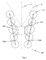
- a rotary wing aircraft 100 is shown with a total of ten rotors 110.
- the rotors 110 are arranged on carrier elements 120a, 120b along both sides of a longitudinal axis L of the aircraft.
- the carrier elements 120a, 120b are connected by bracing elements 130.
- Attached to the bracing members 130 near the center of gravity of the aircraft is a body member 140.
- the body member 140 serves to support the control electronics and power supply (not shown) and any optical and / or sensory elements.
- plastic screws (not shown). These generally have high resistance to tensile and compressive stress and reduced resistance to shear forces. As a result, they can act as predetermined breaking points, while at the same time they do not adversely affect the carrying capacity and stability of the aircraft. Furthermore, plastic screws are lightweight and inexpensive to manufacture.
- the plastic screws are also suitable for the fact that the aircraft can be easily disassembled and rebuilt. On the one hand, this facilitates transport, on the other hand, defective components can be exchanged easily and quickly.
- the carrier elements 120a, 120b are aligned rectilinearly and axially symmetrically on both sides of the longitudinal axis L.
- a free field of view is defined in the front region of the aircraft.
- a free field of view is defined in the front region of the aircraft.
- a range of ⁇ 30 ° to the longitudinal axis L, starting from the body member 140 there are neither rotor nor Carrier element parts or other components of the aircraft in the field of view. It thereby allows an optical or sensory element (not shown) mounted on the fuselage 140 to detect the environment ahead of the aircraft without interference. In particular, this makes it possible to continuously detect the environment of the aircraft from an area above the rotor level, through the rotor level, and to an area below the rotor level without components of the aircraft projecting into the detection area.
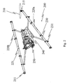
- Fig. 2 shows an oblique view of another embodiment of the invention. For clarity, seven of the eight rotors 210 and motors 215 are not shown.
- Two support elements 220a, 220b are arranged as an open V and connected to each other via X-shaped struts 230.
- the connections between the support elements 220a, 220b and the bracing elements 230 are provided by clamps 231.
- the clamps are less resistant than the carrier elements 220a, 220b and the bracing elements 230 and can therefore serve as predetermined breaking points. In addition, they can be solved quickly and easily, so that the support members 220 a, 220 b can be removed from the bracing elements 230.
- each support member 220a and 220b there are four motor holders 211 equidistant from each other on which are mounted motors 215 which drive the rotors.
- the motors 215 are brushless and sensorless electric motors which are each controlled via an assigned power electronics (not shown). Each individual rotor is associated with an electric motor, so that there is a maximum maneuverability.
- a fuselage element 240 is mounted vibration-damped.
- the body member 240 carries a moveable camera mount 250.
- the configuration is tuned such that the body member 240 is behind and the camera mount 250 is located forward of the aircraft's center of gravity. Both elements together yield Mounting a camera (not shown) on the camera mount a neutral center of gravity, so that when a hover of the aircraft all rotors provide the same thrust.
- the camera mount 250 is pivotable about ⁇ 120 ° with respect to a horizontal plane of the aircraft and ⁇ 30 ° with respect to a vertical plane of the aircraft such that a camera (not shown) pivots above, in front of and below the aircraft by simply pivoting can record.
- the pivoting also roll and pitching movements of the aircraft, as caused for example by acceleration and turning flight can be actively compensated.
- the support elements 220a, 220b are hollow bodies with a diameter which allows the power electronics to be accommodated to drive the motors 215.
- the cables (not shown) for power supply and control of the individual components, starting from the body element 240, are guided through the cable openings 221 into the carrier elements 220a, 220b and subsequently within the latter.
- plugs are provided for disconnecting the cable connection. So that can be done in Fig. 2 shown system can be disassembled in a few simple steps in three handy parts.
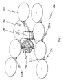
- Fig. 3 shows an oblique view of yet another embodiment of the invention.
- the aircraft includes two support members 320a, 320b, which are arranged as an open V.
- the support elements 320a, 320b are connected to one another via X-shaped strut elements 330.
- Each support member 320a and 320b is formed of a pair of hollow bodies, respectively. Between each pair of hollow bodies a plurality of short connecting webs 312 are mounted, some of which at the same time as motor mounts (not shown) or to Connection 331 of the respective carrier element 320a, 320b serve with the bracing elements 330.
- the node of the X-shaped bracing elements 330 lies on the longitudinal axis behind the spatial center of the aircraft 300.
- a torso element 340 is mounted vibration-damped.
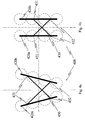
- Fig. 4a and 4b illustrate the mechanism of folding according to a preferred embodiment of the invention.
- Fig. 4a shows the unfolded state in which the aircraft 400 is operated.
- Fig. 4b shows the collapsed state in which the aircraft 400 is transported.
- the rear (more closely connected) connections 432 between the carrier element 420a, 420b and X-shaped bracing member 430 are designed to be rotatable and the front (further apart) connections 431 detachably formed.
- the front connections 431 are released and the support elements 420a, 420b then inwardly around the rear connections 432, ie towards each other, in the in Fig. 4b shown folded state turned.
- the support members 420a, 420b are arranged close to each other in parallel.
- the front arms of the bracing member 430 are retracted telescopically and thus shortened.
- the bracing member 430 is reconnected to the support members 420a, 420b elsewhere via the front links 431. In this in Fig. 4b shown final configuration, the entire aircraft can be transported firmly mounted in one piece.
- the support members may be permanently connected or integrally formed with the fuselage and / or strut members.
- an aircraft according to the invention has equivalent or nearly equivalent flight characteristics with respect to each of the three axes longitudinal axis, transverse axis and vertical axis, so that the longitudinal axis is only the preferred, not the exclusive, direction of forward motion of the aircraft is.
- a rotary wing aircraft according to the invention is used for a manned flight, so that the advantageous properties mentioned herein benefit the persons located thereon. It is therefore intended that the specification and examples be considered as exemplary only, with the scope of the invention being defined by the appended claims.
Landscapes
- Engineering & Computer Science (AREA)
- Mechanical Engineering (AREA)
- Remote Sensing (AREA)
- Aviation & Aerospace Engineering (AREA)
- Accessories Of Cameras (AREA)
- Tires In General (AREA)
- Gyroscopes (AREA)
- Toys (AREA)
Description
Diese Erfindung betrifft im Allgemeinen Drehflügelfluggeräte mit einer Mehrzahl von Rotoren. Spezieller betrifft die Erfindung ein Drehflügelfluggerät, das sich insbesondere für die Erstellung von Photo- und Videoaufnahmen aus der Luft eignet.This invention relates generally to rotary wing aircraft having a plurality of rotors. More particularly, the invention relates to a rotary wing aircraft, which is particularly suitable for the creation of photo and video recordings from the air.
Drehflügelfluggeräte mit einer Mehrzahl von Rotoren sind im Stand der Technik gut bekannt. Derzeit am weitesten verbreitet sind Quadrokopter, die durch vier in einer Ebene angeordnete, im Wesentlichen senkrecht nach unten wirkende Rotoren definiert sind. Der Vorteil von Drehflügelfluggeräten mit mehreren Rotoren besteht im Allgemeinen darin, dass die drei Flugachsen Längsachse, Querachse und Hochachse allein durch Variation des Schubs der einzelnen Rotoren angesteuert werden können.Rotary vane airplanes having a plurality of rotors are well known in the art. Currently most widespread are quadrocopters, which are defined by four arranged in a plane, essentially vertically downwardly acting rotors. The advantage of rotary vane airplanes with multiple rotors is generally that the three axes of flight longitudinal axis, transverse axis and vertical axis can be controlled solely by varying the thrust of the individual rotors.
Derartige Fluggeräte werden immer häufiger zur Erstellung von Photo- und Videoaufnahmen aus der Luft verwendet. Dabei kommen insbesondere modellhelikopterähnliche, manuell gesteuerte oder autonome Drehflügelfluggeräte zum Einsatz.Such aircraft are increasingly used for the production of photo and video recordings from the air. In particular, model helicopter-like, manually controlled or autonomous rotary-wing aircraft are used.
Aus der
Aus der
Aus der
Der Artikel "
Die
Die
Die
Die
Die
Das weiteren ist Dokument
Die Fluggeräte des Standes der Technik haben gemeinsam, dass Lasten wie beispielsweise optische oder sensorische Elemente, z. B. zur Photo- oder Videoaufzeichnung oder Umwelterfassung, entweder unterhalb oder oberhalb der Rotorebene zentral am Fluggerät angebracht werden müssen, um die Last gleichmäßig auf die einzelnen Rotoren zu verteilen. Eine Konsequenz daraus ist, dass das Blickfeld der optischen oder sensorischen Elemente durch die Rotorebene und andere Teile des Trägersystems begrenzt ist. Im Falle von Photo- und Videoaufzeichnungen beispielsweise sind bei zu großem Öffnungswinkel oder zu geringer Neigung der Kamera nach unten (bei Montage unterhalb der Rotorebene) oder nach oben (bei Montage oberhalb der Rotorebene) Teile des Trägersystems im Bild.The aircraft of the prior art have in common that loads such as optical or sensory elements, for. As for photo or video recording or environmental detection, either below or above the rotor level centrally on the aircraft must be installed to distribute the load evenly on the individual rotors. A consequence of this is that the field of vision of the optical or sensory Elements is limited by the rotor plane and other parts of the carrier system. In the case of photo and video recordings, for example, parts of the support system are in the picture when the camera angle is too low or too low (when mounted below the rotor plane) or upward (when mounted above the rotor plane).
Darüber hinaus muss sich ein Drehflügelfluggerät systembedingt und unabhängig von der Anzahl der Rotoren in Fahrtrichtung neigen, um in diese Richtung zu beschleunigen. Das erfordert in manchen Anwendungen eine aktive Neigungskompensation für die optischen oder sensorischen Elemente, um sicherzustellen, dass das zu erfassende Objekt den Erfassungsbereich nicht aufgrund der Neigung verlässt. Im Stand der Technik ragen in Folge der Neigungskompensation bei zu großen Neigungswinkeln Teile des Trägersystems in den Erfassungsbereich. Dadurch wird der ungestörte Bildraum dieser Elemente weiter eingeschränkt.In addition, a rotary wing aircraft system dependent and regardless of the number of rotors in the direction of travel must tilt in order to accelerate in this direction. This requires, in some applications, active tilt compensation for the optical or sensory elements to ensure that the object to be detected does not leave the coverage area due to the slope. In the prior art, parts of the carrier system protrude into the detection range as a result of the inclination compensation at excessive angles of inclination. This further restricts the undisturbed image space of these elements.
Es ist folglich Aufgabe der Erfindung, ein Drehflügelfluggerät bereitzustellen, das diese Nachteile des Standes der Technik überwindet. Diese Aufgabe wird durch die Merkmale des Anspruchs 1 gelöst, während vorteilhafte Ausführungsformen in den abhängigen Ansprüchen definiert sind.It is therefore an object of the invention to provide a rotary wing aircraft which overcomes these disadvantages of the prior art. This object is solved by the features of
Gemäß dem oben genannten Zweck wird ein Drehflügelfluggerät bereitgestellt, umfassend zumindest vier an Trägerelementen angeordnete Rotoren, wobei die Rotoren und Trägerelemente derart angeordnet sind, dass entlang einer Längsachse des Fluggeräts zumindest zwischen zwei endständigen Rotoren ein freies Sichtfeld definiert wird und die Trägerelemente eine geradlinige Verbindung zwischen den Rotoren jeweils auf einer Seite der Längsachse bereitstellen, wobei die Trägerelemente V-förmig symmetrisch bezüglich der Längsachse angeordnet sind.According to the above-mentioned purpose, there is provided a rotary wing apparatus comprising at least four rotors arranged on support members, wherein the rotors and support members are arranged such that along a longitudinal axis of the aircraft at least between two terminal rotors a free field of view is defined and the support members form a straight line connection provide the rotors respectively on one side of the longitudinal axis, wherein the support elements are arranged V-shaped symmetrically with respect to the longitudinal axis.
Dadurch wird es auf dem erfindungsgemäßen Fluggerät angeordneten optischen und/oder sensorischen Elementen erstmals ermöglicht, kontinuierlich und störungsfrei sowohl die Bereiche oberhalb und unterhalb der Rotorebene, als auch den Bereich innerhalb der Rotorebene entlang zumindest einer Richtung der Längsachse des Fluggeräts zu erfassen. So kann insbesondere ein einzelnes optisches und/oder sensorisches Element von einem Bereich oberhalb der Rotorebene, durch die Rotorebene hindurch, und zu einem Bereich unterhalb der Rotorebene, und zurück, geschwenkt werden, ohne dass während des Schwenkens Bauteile des Fluggeräts in den Bild- oder Erfassungsbereich des optischen und/oder sensorischen Elements ragen.As a result, optical and / or sensory elements arranged on the aircraft according to the invention are for the first time made possible to detect both the areas above and below the rotor plane and the area within the rotor plane along at least one direction of the longitudinal axis of the aircraft continuously and without interference. In particular, a single optical and / or sensory element can be swiveled from a region above the rotor plane, through the rotor plane, and to a region below the rotor plane, and back, without being interrupted during the process Schwenkens components of the aircraft in the image or detection range of the optical and / or sensory element protrude.
Im Gegensatz zu Systemen des Standes der Technik ist es bei dem erfindungsgemäßen Fluggerät beispielsweise einer Kamera möglich, Gegenstände oder Personen bei Filmaufnahmen ohne Konfigurationsänderung sowohl von unten als auch von schräg vorne, von vorne oder von oben zu erfassen. Des Weiteren können bei dem erfindungsgemäßen Fluggerät in einem einzigen Flug Aufnahmen von unten (z.B. beim Unterfliegen einer Brücke) als auch von der Seite oder von oben gemacht werden. Erstmals ist es für die verschiedenen Aufnahmentypen nicht notwendig, die Kamera umzumontieren. Der Schwenkbereich der Kamera kann erheblich größer sein als bei herkömmlichen Systemen.In contrast to systems of the prior art, it is possible in the aircraft according to the invention, for example, a camera to capture objects or people during filming without configuration change both from below and from diagonally forward, from the front or from above. Further, in the aircraft of the present invention, in a single flight, shots may be taken from below (e.g., underwing a bridge) as well as from the side or from above. For the first time it is not necessary for the different types of shooting to remount the camera. The swivel range of the camera can be considerably larger than with conventional systems.
Somit kann die Kamera bei dem erfindungsgemäßen Fluggerät jede beliebige Orientierung im Raum annehmen, d.h. sphärisch jeden Punkt in der Umgebung erfassen. Ein geeigneter Schwenkmechanismus kann hierbei die geschilderte Schwenkung der Kamera in vertikaler Richtung bewerkstelligen, während die horizontale Änderung des Erfassungsbereichs über die Drehung des gesamten Fluggeräts um seine Hochachse erfolgt.Thus, in the aircraft of the invention, the camera can assume any orientation in space, i. Spherically capture every point in the environment. A suitable pivoting mechanism can in this case accomplish the described pivoting of the camera in the vertical direction, while the horizontal change of the detection range takes place via the rotation of the entire aircraft about its vertical axis.
Darüber hinaus kann der Schwenkbereich der Kamera bei dem erfindungsgemäßen Fluggerät unabhängig von einer Nickbewegung des Fluggeräts sein. Mit einer neigungskompensierten Aufhängung der optischen und/oder sensorischen Elemente kann sich das Fluggerät zum Beschleunigung und Abbremsen beliebig neigen, ohne dass die Erfassung durch in den Erfassungsbereich ragende Rotor- oder Trägerteile gestört wird. Das ist sowohl bei einer aktuellen Ausrichtung der Erfassung nach unten, nach vorne als auch nach oben gewährleistet.In addition, the pivoting range of the camera in the aircraft according to the invention can be independent of a pitching motion of the aircraft. With a tilt-compensated suspension of the optical and / or sensory elements, the aircraft may tend to accelerate and decelerate as desired, without the detection being disturbed by rotor or carrier parts projecting into the detection area. This is guaranteed both with an up-to-date orientation of recording downwards, forwards as well as upwards.
Ein solches Fluggeräts kann überall da eingesetzt werden, wo bisher herkömmliche Helikopter und Quadrokoptersysteme Einsatz finden. Es kann aber auch bei Aufnahmen eingesetzt werden, die einen wesentlich größeren vertikalen Bewegungsspielraum der Kamera erfordern.Such an aircraft can be used wherever conventional helicopters and quadrocopter systems have hitherto been used. But it can also be used in recordings that require a much greater vertical range of motion of the camera.
Die Längs- bzw. Rollachse des Fluggeräts im Zusammenhang mit der Erfindung entspricht hierbei der Achse durch den Schwerpunkt des Fluggeräts, die sich in der üblichen, bevorzugten oder bauartbedingten Richtung der Vorwärtsbewegung des Fluggeräts erstreckt. Sie entspricht üblicherweise, jedoch nicht zwingend, einer längsten Symmetrieachse des Fluggeräts. Als endständige Rotoren kommen die in der Richtung der Längsachse des Fluggeräts vorne oder hinten liegenden Rotoren in Betracht.The longitudinal or roll axis of the aircraft in the context of the invention in this case corresponds to the axis through the center of gravity of the aircraft, which extends in the usual, preferred or design-related direction of forward movement of the aircraft. It usually, but not necessarily, corresponds to a longest symmetry axis of the aircraft. As terminal rotors are in the direction of the longitudinal axis of the aircraft front or rear rotors into consideration.
Der Begriff freies Sichtfeld im Zusammenhang mit der Erfindung bedeutet einen Bereich, der frei von Bauteilen des Fluggeräts ist, so dass ausgehend von einem Ausgangspunkt innerhalb der räumlichen Begrenzungen des Fluggeräts eine störungsfreie Sicht bzw. Erfassung der Umgebung außerhalb der räumlichen Begrenzungen des Fluggeräts, beispielsweise durch optische und/oder sensorische Elemente, gewährleistet ist.The term free field of view in the context of the invention means an area that is free of components of the aircraft, so that starting from a starting point within the spatial limitations of the aircraft trouble-free vision or detection of the environment outside the spatial limitations of the aircraft, for example optical and / or sensory elements, is ensured.
Bevorzugt wird das freie Sichtfeld entlang der Längsachse ausgehend von einem Punkt nahe dem Schwerpunkt des Fluggeräts definiert. Mit anderen Worten kommt als Ausgangspunkt innerhalb der räumlichen Begrenzungen des Fluggeräts insbesondere ein Punkt nahe dem Schwerpunkt des Fluggeräts in Betracht. Dies hat den Vorteil, dass, sofern Lasten wie optische und/oder sensorische Elemente zum Einsatz kommen, diese nahe dem Schwerpunkt angeordnet werden können, so dass die Flugeigenschaften des Fluggeräts so wenig wie möglich beeinflusst werden.Preferably, the free field of view along the longitudinal axis is defined starting from a point near the center of gravity of the aircraft. In other words, as a starting point within the spatial limits of the aircraft in particular a point near the center of gravity of the aircraft into consideration. This has the advantage that, if loads such as optical and / or sensory elements are used, they can be arranged close to the center of gravity, so that the flight characteristics of the aircraft are influenced as little as possible.
Bevorzugt kann das freie Sichtfeld eine horizontale Ausdehnung bezüglich der Längsachse von mehr als ± 15° aufweisen, beispielsweise von mehr als ± 30° und insbesondere von mehr als ± 45°, ausgehend von einem Punkt nahe dem Schwerpunkt des Fluggeräts. Die vertikale Ausdehnung des freien Sichtfelds kann bevorzugt größer als ± 15° sein, beispielsweise größer als ± 60°, größer als ± 90° und am insbesondere größer als + 120° bezüglich der Längsachse, ausgehend von einem Punkt nahe dem Schwerpunkt des Fluggeräts.The free field of view may preferably have a horizontal extension with respect to the longitudinal axis of more than ± 15 °, for example of more than ± 30 ° and in particular of more than ± 45 °, starting from a point near the center of gravity of the aircraft. The vertical extent of the free field of view may preferably be greater than ± 15 °, for example greater than ± 60 °, greater than ± 90 ° and in particular greater than + 120 ° with respect to the longitudinal axis, starting from a point near the center of gravity of the aircraft.
Je größer der Öffnungswinkel ist, desto größer ist der Bereich, der erfasst oder abgebildet werden kann, desto kleiner kann beispielsweise die Brennweite eines Objektivs gewählt werden. Ein Öffnungswinkel von 30° entspricht in etwa dem Bildwinkel, den ein Objektiv von 80 mm Brennweite im Kleinbildformat abbildet (Teleobjektiv). Ein Öffnungswinkel von 90° entspricht in etwa dem Bildwinkel, den ein Objektiv von 22 mm Brennweite im Kleinbildformat abbildet (Weitwinkelobjektiv). Eine große vertikale Ausdehnung des freien Sichtfelds hat darüber hinaus den Vorteil, dass ein optisches und/oder sensorisches Element in der Vertikalen geschwenkt werden kann, sei es zur Neigungskompensation oder zu einem störungsfreien Schwenken von einem Bereich oberhalb der Rotorebene, durch die Rotorebene hindurch, und zu einem Bereich unterhalb der Rotorebene und umgekehrt.The larger the opening angle, the larger the area that can be detected or imaged, the smaller, for example, the focal length of a lens can be selected. An opening angle of 30 ° corresponds approximately to the angle of view that a lens of 80mm focal length in 35mm format (telephoto lens). An opening angle of 90 ° corresponds approximately to the angle of view, which a lens of 22 mm focal length in 35mm format (wide-angle lens). A large vertical extent of the free field of view also has the advantage that an optical and / or sensory element can be pivoted in the vertical, be it for tilt compensation or trouble-free pivoting from an area above the rotor plane, through the rotor plane, and to a region below the rotor plane and vice versa.
Bevorzugt können die zumindest vier Rotoren paarweise auf gegenüberliegenden Seiten der Längsachse des Drehflügelfluggeräts auf den Trägerelementen angeordnet sein, wobei zumindest das bezüglich der Längsachse vordere Paar von Rotoren derart mit Abstand zueinander angeordnet sein kann, dass zwischen dem Paar von Rotoren das freie Sichtfeld definiert wird. Bevorzugt kann dieser Abstand mindestens einen Rotordurchmesser oder mehr betragen.Preferably, the at least four rotors may be arranged in pairs on opposite sides of the longitudinal axis of the rotary-wing aircraft on the carrier elements, wherein at least the front relative to the longitudinal axis of the pair of rotors may be spaced apart such that the free field of view is defined between the pair of rotors. Preferably, this distance may be at least one rotor diameter or more.
In einer bevorzugten Ausführungsform der Erfindung können sich die Trägerelemente im Wesentlichen geradlinig auf beiden Seiten der Längsachse erstrecken. Ein geradliniges Trägerelement bietet den Vorteil, dass die Kräfte der einzelnen darauf angeordneten Rotoren zum einen auf einem sehr kompakten Bauteil wirken und zum anderen keine Torsion des Bauteils erzeugen. Somit bringt eine geradlinige Verbindung zwischen den einzelnen Rotoren jeweils auf einer Seite der Längsachse eine hohe Steifigkeit bei gleichzeitig niedrigem Materialaufwand mit sich, insbesondere im Vergleich zu einer individuellen Verbindung jedes einzelnen Rotors zum Schwerpunkt des Fluggeräts. Zudem können an oder in den Verbindungsstücken zwischen den einzelnen Rotoren Kabel und/oder Leistungs- oder Steuerungselektronik untergebracht werden. Dies dient einem einfachen und übersichtlichen und darüber hinaus verschleißarmen Aufbau des Fluggeräts. Des Weiteren sind geradlinige Trägerelemente einfach zu bearbeiten und günstig in der Beschaffung.In a preferred embodiment of the invention, the carrier elements may extend substantially rectilinearly on both sides of the longitudinal axis. A straight-line carrier element has the advantage that the forces of the individual rotors arranged thereon, on the one hand, act on a very compact component and, on the other hand, do not produce any torsion of the component. Thus, a straight connection between the individual rotors on each side of the longitudinal axis brings a high rigidity with low material costs at the same time, especially in comparison to an individual connection of each rotor to the center of gravity of the aircraft. In addition, cables and / or power or control electronics can be accommodated on or in the connecting pieces between the individual rotors. This serves a simple and clear and also low-wear construction of the aircraft. Furthermore, linear support elements are easy to work on and inexpensive to procure.
Die Trägerelemente können mit Abstand zueinander angeordnet sein, miteinander verbunden sein oder integral ausgebildet sein. Bevorzugt können die Trägerelemente eine V-Form beschreiben. Bei einer geschlossenen V-Anordnung berühren sich die Trägerelemente im Schnittpunk mit der Symmetrieachse oder sind dort verbunden oder integral ausgebildet, während sie bei einer offenen V-Anordnung mit Abstand zueinander angeordnet sind. Die Trägerelemente können auch eine U-Form, H-Form oder II-Form beschreiben.The carrier elements may be arranged at a distance from each other, be connected to each other or be integrally formed. Preferably, the carrier elements can have a Describe V shape. In a closed V-arrangement, the support elements in the interface with the symmetry axis touch or are connected or integrally formed, while they are arranged at an open V-arrangement with distance to each other. The support elements may also describe a U-shape, H-shape or II-shape.
Erfindungsgemäß sind die Trägerelemente V-förmig symmetrisch bezüglich der Längsachse angeordnet. Durch eine derartige Ausführung kann ein Öffnungswinkel erzeugt werden, wodurch vorteilhaft das freie Sichtfeld zwischen den am meisten beabstandeten Rotoren weiter vergrößert wird. Zudem gestattet eine derartige V-Anordnung einen einfachen und insbesondere verwindungssteifen Aufbau, da nur ein Teil der Rotoren einen vergrößerten Abstand zum Schwerpunkt des Fluggeräts aufweist. Die übrigen Rotoren können sich nahe dem Schwerpunkt des Fluggeräts befinden, so dass sich kurze Verbindungswege zum Schwerpunkt ergeben und somit lediglich kurze und nicht zusätzlich verstärkte Strukturen zur Herstellung einer inneren Steifigkeit benötigt werden.According to the invention, the carrier elements are arranged in a V-shape symmetrical with respect to the longitudinal axis. By such an embodiment, an opening angle can be generated, whereby advantageously the free field of view between the most spaced rotors is further increased. In addition, such a V-arrangement allows a simple and in particular torsion-resistant construction, since only a portion of the rotors has an increased distance to the center of gravity of the aircraft. The remaining rotors may be located near the center of gravity of the aircraft, so that there are short connection paths to the center of gravity and thus only short and not additionally reinforced structures for producing an inner stiffness are needed.
In einer weiteren bevorzugten Ausführungsform der Erfindung kann das Drehflügelfluggerät ferner zumindest ein Verstrebungselement umfassen, das zur Verbindung und/oder Verstrebung der Trägerelemente dienen kann. Damit kann eine zusätzliche Steifigkeit des Fluggeräts bereitgestellt werden. Besonders vorteilhaft kann das zumindest eine Verstrebungselement in Form eines X ausgebildet sein, d. h. ein besonders bevorzugter, verwindungssteifer Aufbau ergibt sich, wenn die geradlinigen Trägerelemente über kreuzförmige bzw. X-förmige Verstrebungselemente miteinander verbunden sind. Ein rechtwinkliger, starrer Knoten im X biete eine große Festigkeit und einfache Montage, ein lösbarer oder beweglicher Knoten im X begünstigt die Möglichkeiten einer Zerlegung oder eines Zusammenklappens des Fluggeräts.In a further preferred embodiment of the invention, the rotary-wing aircraft can further comprise at least one bracing element, which can serve for the connection and / or bracing of the carrier elements. Thus, an additional rigidity of the aircraft can be provided. Particularly advantageously, the at least one bracing element may be in the form of an X, d. H. a particularly preferred, rigid construction results when the linear support elements are connected to each other via cross-shaped or X-shaped strut elements. A right-angled, rigid knot in the X offers great strength and easy assembly, a detachable or movable knot in the X favors the possibilities of dismantling or collapsing the aircraft.
In einer besonders bevorzugten Ausführungsform der Erfindung können die Verbindungen zwischen den Trägerelementen und dem zumindest einen Verstrebungselement lösbar ausgebildet sein. Dadurch wird ein einfach zerlegbarer, modularer Aufbau erreicht, was nicht nur einem schnellen Auf- und Abbau des Fluggeräts, sondern auch einem einfachen Austausch von beschädigten Teilen zugute kommt.In a particularly preferred embodiment of the invention, the connections between the carrier elements and the at least one strut element can be made detachable. This achieves an easily dismountable, modular design, which not only benefits the quick assembly and disassembly of the aircraft, but also an easy replacement of damaged parts.
Als lösbare Verbindungen kommen insbesondere Rast-, Steck- und Schraubverbindungen in Betracht, die vorteilhaft mit geeigneten Verriegelungsmechanismen bereitgestellt sind. Die lösbaren Verbindungen können ferner über einen Entriegelungsmechanismus verfügen, der es erlaubt, dass sich die Verbindungen bei einer unkontrollierten Krafteinwirkung lösen. Im Falle einer unsanften Landung des Fluggeräts würden somit erst die lösbaren Verbindungen getrennt werden, bevor weitere Bauteile Schaden nehmen. Eine derartige Konstruktion kann in vielen Fällen dazu beitragen, dass ein Aufprall des Fluggeräts nicht zu einer Beschädigung der Bauteile sondern lediglich zu einer Lösung der Verbindungen führen würde. Als Entriegelungsmechanismus kommen sämtliche im Stand der Technik bekannten Vorrichtungen in Betracht, insbesondere leichtgewichtige Entriegelungsmechanismen von ausreichender Haltbarkeit.Detentable connections are in particular locking, plug-in and screw connections into consideration, which are advantageously provided with suitable locking mechanisms. The releasable connections may further include an unlocking mechanism that allows the connections to disengage under an uncontrolled force. In the event of a rude landing of the aircraft, the detachable connections would first be disconnected before further components would be damaged. Such a construction can in many cases contribute to the fact that an impact of the aircraft would not lead to damage of the components but only to a solution of the connections. As unlocking all known in the art devices come into consideration, in particular lightweight release mechanisms of sufficient durability.
In einer weiteren, besonders bevorzugten Ausführung der Erfindung können die Verbindungen zwischen den Trägerelementen und dem zumindest einen Verstrebungselement so ausgeführt werden, dass das gesamte Fluggerät mit wenigen Handgriffen in einen zusammengeklappten Zustand zusammengeklappt werden kann. Insbesondere können zu diesem Zweck hintere (enger zusammen liegende) Verbindungen drehbar ausgeführt sein und vordere (weiter auseinander liegende) Verbindungen lösbar ausgebildet sein. Bei einer derartigen Ausgestaltung können zum Zusammenklappen die vorderen Verbindungen gelöst werden und die Trägerelemente können dann um die hinteren Verbindungen nach innen, d.h. aufeinander zu, in den zusammengeklappten Zustand gedreht werden. Anschließend kann mittels der vorderen Verbindungen das zumindest eine Verstrebungselement erneut mit den Trägerelementen, eventuell an anderer Stelle, verbunden werden. Im zusammengeklappten Zustand wären somit beide Trägerelemente mit verringertem Abstand bevorzugt parallel zueinander angeordnet, wobei das gesamte Fluggerät fest montiert in einem Stück transportiert werden kann.In a further, particularly preferred embodiment of the invention, the connections between the carrier elements and the at least one bracing element can be designed so that the entire aircraft can be folded into a collapsed state with a few simple steps. In particular, for this purpose, rear (closer together) connections can be made rotatable and front (further apart) connections can be made detachable. In such a configuration, for folding, the front connections may be released and the support members may then be turned inwardly about the rearward connections, i. towards each other, are turned in the folded state. Subsequently, by means of the front connections, the at least one strut element can again be connected to the carrier elements, possibly elsewhere. In the folded state, therefore, both carrier elements would be arranged at a reduced distance preferably parallel to each other, wherein the entire aircraft can be transported firmly mounted in one piece.
Vorteilhaft kann das Verstrebungselement so ausgestaltet sein, dass dessen Ausleger während des Zusammenklappens verkürzt werden können, beispielsweise teleskopartig. So können beim Zusammenklappen des Fluggeräts vor allem die vorderen Ausleger vor dem erneuten Verbinden mit den Trägerelementen verkürzt werden, was sich positiv auf die Kompaktheit im zusammengeklappten Zustand auswirkt.Advantageously, the bracing element can be designed such that its boom can be shortened during the folding, for example telescopically. Thus, when folding the aircraft especially the front boom in front of the reconnecting with the support elements are shortened, which has a positive effect on the compactness in the folded state.
Bei einem kreuzförmigen Verstrebungselement kann es besonders vorteilhaft sein, wenn der Winkel im Kreuzungspunkt veränderbar ist. Dadurch wird es ermöglicht, dass die Trägerelemente im zusammengeklappten Zustand mit besonders verringertem Abstand zueinander angeordnet werden können.In the case of a cross-shaped strut element, it may be particularly advantageous if the angle can be changed at the point of intersection. This makes it possible that the support elements can be arranged in the folded state with a particularly reduced distance from each other.
Vorteilhaft kann darüber hinaus das zumindest eine Verstrebungselement von geringerer mechanischer Belastbarkeit als die Trägerelemente ausgebildet sein. Somit kann das zumindest eine Verstrebungselement im Falle einer unkontrollierten Krafteinwirkung als Sollbruchstelle wirken. Auch dies kann dazu beitragen, dass ein Aufprall des Fluggeräts nicht zu einer Beschädigung wesentlicher Bauteile sondern lediglich zu einem Brechen des zumindest einen Verstrebungselements führen würde.Advantageously, moreover, the at least one bracing element of lesser mechanical load capacity than the carrier elements may be formed. Thus, the at least one strut element in the event of an uncontrolled force acting as a predetermined breaking point. This, too, can contribute to an impact of the aircraft not leading to damage of essential components but merely to a breakage of the at least one bracing element.
Die Träger- und Verstrebungselemente können aus Leichtbaumaterialien wie Aluminium, Magnesium oder Kohlefaserwerkstoffe oder dergleichen gebildet sein. Bevorzugt umfassen diese Elemente zumindest einen Profilträger oder Hohlträger, insbesondere einen I-, U-, Z-, L-, H- oder T-Träger, eine Doppeltraverse, ein Rund- oder Vierkantrohr, massiv oder hohl ausgebildet oder eine Kombination davon.The support and bracing elements may be formed of lightweight materials such as aluminum, magnesium or carbon fiber materials or the like. These elements preferably comprise at least one profile beam or hollow beam, in particular an I, U, Z, L, H or T beam, a double beam, a round or square pipe, solid or hollow or a combination thereof.
Vorteilhaft können die Träger- und Verstrebungselemente hohl ausgebildet sein. Dies dient zum einen der Gewichtseinsparung. Zum anderen lassen sich im Hohlraum der Elemente beispielsweise eine Kabelführung, eine Leistungselektronik, eine Steuerungselektronik, eine Energieversorgung und/oder Motoren zum Antrieb der Rotoren unterbringen.Advantageously, the carrier and strut elements may be hollow. This serves on the one hand the weight saving. On the other hand, in the cavity of the elements, for example, a cable guide, a power electronics, a control electronics, a power supply and / or motors for driving the rotors accommodate.
Gemäß einem Aspekt der Erfindung kann die Anzahl der Rotoren so gewählt werden, dass eine Redundanz des Auftriebs gegeben ist, so dass die Flug- und Manövrierfähigkeit des Fluggeräts auch bei Ausfall eines Rotors erhalten bleibt. Redundanz ist insbesondere dann gegeben, wenn in jedem Quadranten, die zwischen der Längsachse und einer Querachse des Fluggeräts definiert werden, mehr als ein Rotor wirkt. In einer besonders bevorzugten Ausführungsform der Erfindung kann daher das Drehflügelfluggerät zumindest acht Rotoren umfassen. Bei Ausfall eines oder mehrerer Rotoren können die verbleibenden Rotoren dann so angesteuert werden, dass das Fluggerät flugtauglich bleibtAccording to one aspect of the invention, the number of rotors may be selected to provide redundancy of lift, so that the flight and maneuverability of the aircraft is maintained even in the event of a rotor failure. Redundancy is especially given when more than one rotor acts in each quadrant defined between the longitudinal axis and a transverse axis of the aircraft. In a particularly preferred embodiment of the invention, therefore, the rotary wing aircraft can at least eight Include rotors. In case of failure of one or more rotors, the remaining rotors can then be controlled so that the aircraft remains airworthy
In einer weiteren bevorzugten Ausführungsform der Erfindung kann das Drehflügelfluggerät ferner ein Rumpfelement umfassen. Das Rumpfelement befindet sich vorteilhaft in der Nähe des Schwerpunkts des Fluggeräts und kann als Basis bzw. Aufnahme für die Steuerungs- und Leistungselektronik und die Energieversorgung, sowie als das Verstrebungselement zu den Trägerelementen dienen. Ferner können am Rumpfelement optische und/oder sensorische Elemente oder eine Halterung für optische und/oder sensorische Elemente angeordnet sein. Eine Konzentration dieser Lasten in der Nähe des Schwerpunkts des Fluggeräts hat verbesserte Flugeigenschaften zur Folge.In a further preferred embodiment of the invention, the rotary wing aircraft may further comprise a body member. The fuselage element is advantageously located near the center of gravity of the aircraft and can serve as a basis or receptacle for the control and power electronics and the power supply, as well as the strut element to the support elements. Furthermore, optical and / or sensory elements or a holder for optical and / or sensory elements can be arranged on the body element. Concentrating these loads near the center of gravity of the aircraft results in improved flight characteristics.
Vorteilhaft kann das Rumpfelement bezüglich der übrigen Struktur schwingungsgedämpft angeordnet sein. Dadurch gelingt eine Entkoppelung der optional am Rumpfelement angebrachten Komponenten von den durch die Rotoren erzeugten Schwingungen. Im Falle der optischen und/oder sensorischen Elemente trägt dies zu einer verbesserten Qualität der erfassten Daten oder Bilder bei. Als Schwingungsdämpfung kommen sämtliche im Stand der Technik bekannten Vorrichtungen und Verfahren in Betracht, wie beispielsweise Gummitüllen, Federelemente etc. Durch die schwingungsgedämpfte Aufhängung des gesamten Rumpfelements wird die gesamte Masse der Rumpfeinheit inklusive der Energieversorgung vorteilhaft als Masse zur Dämpfung hochfrequenter Vibrationen genutzt.Advantageously, the body element can be arranged so as to be damped with respect to the rest of the structure. As a result, a decoupling of the optionally mounted on the body element components succeeds from the vibrations generated by the rotors. In the case of the optical and / or sensory elements, this contributes to an improved quality of the captured data or images. As vibration damping are all known in the art devices and methods into consideration, such as rubber grommets, spring elements, etc. Due to the vibration damped suspension of the entire Rumpfelements the entire mass of the fuselage unit including the power supply is advantageously used as a mass for damping high-frequency vibrations.
Vorteilhaft kann die Anordnung sämtlicher Bauteile des Fluggeräts inklusive etwaiger Aufbauten wie optische und/oder sensorische Elemente so gewählt werden, dass der resultierende Schwerpunkt mit einem räumlichen Mittelpunkt des Fluggeräts nahezu oder vollständig zur Deckung kommt. Der räumliche Mittelpunkt des Fluggeräts entspricht dabei einem Punkt mittig innerhalb der räumlichen Begrenzungen des Fluggeräts. Besonders vorteilhaft wäre eine Anordnung, bei der in einem Schwebeflug des Fluggeräts, d.h. ohne Vorwärts- oder Seitwärtsbewegung, alle Rotoren einen gleichen oder nahezu gleichen Schub liefern. Dies wirkt sich zum einen günstig auf die Flugeigenschaften aus, zum anderen verschleißen dadurch die beweglichen Teile wie Motoren und Rotoren in etwa gleich schnell, was die Wartungsintervalle verlängert und die Reparaturanfälligkeit senkt.Advantageously, the arrangement of all components of the aircraft including any structures such as optical and / or sensory elements can be selected so that the resulting center of gravity almost or completely coincides with a spatial center of the aircraft. The spatial center of the aircraft corresponds to a point centrally within the spatial limits of the aircraft. Particularly advantageous would be an arrangement in which in a hovering flight of the aircraft, ie without forward or sideways movement, all rotors provide an equal or nearly same thrust. This has a favorable effect on the flight characteristics, on the other wear out the moving parts such as motors and rotors in about the same speed, which extends the maintenance intervals and reduces the need for repair.
Durch eine beispielhafte Kombination der bevorzugten Konfigurationen "offenes V", "kreuzförmiges rechtwinkliges Verbindungselement" sowie "schwingungsgedämpftes Rumpfelement" kann sich folgender sehr vorteilhafter Aufbau ergeben: Der Knotenpunkt des X-förmigen Verstrebungselements kann auf der Längsachse hinter dem räumlichen Mittelpunkt des Fluggeräts liegen. Das Rumpfelement kann schwingungsgedämpft auf dem kreuzförmigen Verbindungselement montiert werden. An das hinter dem Mittelpunkt befindliche Rumpfelement kann eine sich nach vorne erstreckende schwenkbare Halterung für optische und/oder sensorische Elemente montiert werden. An dieser Halterung angebrachte optische und/oder sensorische Elemente befinden sich dann auf der Längsachse vor dem Rumpfelement und vor dem Mittelpunkt des Fluggeräts. Dadurch kann ein sehr kompakter Aufbau und bei entsprechender Auslegung ein ausgeglichener Schwerpunkt nahe dem räumlichen Mittelpunkt des Fluggeräts und gleichzeitig ein maximales Sichtfeld erreicht werden.By an exemplary combination of the preferred "open V", "cruciform rectangular connector" and "vibration damped body members", the following very advantageous construction may result: the node of the X-shaped bracing member may lie on the longitudinal axis behind the aircraft's center of gravity. The torso element can be mounted vibration-damped on the cross-shaped connecting element. A forwardly extending pivotal support for optical and / or sensory elements may be mounted to the fuselage element located behind the center. Optical and / or sensory elements attached to this holder are then located on the longitudinal axis in front of the fuselage element and in front of the center of the aircraft. As a result, a very compact design and, with appropriate design, a balanced center of gravity near the spatial center of the aircraft and at the same time a maximum field of view can be achieved.
Diese und weitere Einzelheiten, Merkmale und Vorteile des Gegenstandes der Erfindung ergeben sich aus den Unteransprüchen sowie aus der nachfolgenden Beschreibung der zugehörigen Zeichnungen, in denen - beispielhaft - bevorzugte Ausführungsbeispiele der Erfindung dargestellt sind. In den Zeichnungen gilt:
-
Fig. 1 ist eine schematische Draufsicht eines Drehflügelfluggeräts gemäß einer Ausführungsform der Erfindung; -
Fig. 2 ist eine schematische Schrägansicht eines Drehflügelfluggeräts gemäß einer weiteren Ausführungsform der Erfindung. -
Fig. 3 ist eine schematische Schrägansicht eines Drehflügelfluggeräts gemäß noch einer weiteren Ausführungsform der Erfindung. -
Fig. 4a und 4b sind schematische Darstellungen, die den Mechanismus des Zusammenklappens gemäß einer Ausführungsform der Erfindung veranschaulichen.
-
Fig. 1 is a schematic plan view of a rotary wing aircraft according to an embodiment of the invention; -
Fig. 2 is a schematic oblique view of a rotary wing aircraft according to another embodiment of the invention. -
Fig. 3 is a schematic oblique view of a rotary wing aircraft according to yet another embodiment of the invention. -
Fig. 4a and 4b Fig. 3 are schematic diagrams illustrating the mechanism of collapsing according to an embodiment of the invention.
Mit Bezug auf
Die Verbindungen zwischen den einzelnen Elementen sind aus Kunststoffschrauben (nicht gezeigt) ausgebildet. Diese weisen im Allgemeinen eine hohe Widerstandsfähigkeit bezüglich Zug- und Druckbelastung und eine verringerte Widerstandsfähigkeit gegenüber Scherkräften auf. Dadurch können diese als Sollbruchstellen wirken, während sie gleichzeitig die Tragfähigkeit und Stabilität des Fluggeräts nicht negativ beeinflussen. Ferner sind Kunststoffschrauben leichtgewichtig und günstig in der Herstellung.The connections between the individual elements are made of plastic screws (not shown). These generally have high resistance to tensile and compressive stress and reduced resistance to shear forces. As a result, they can act as predetermined breaking points, while at the same time they do not adversely affect the carrying capacity and stability of the aircraft. Furthermore, plastic screws are lightweight and inexpensive to manufacture.
Die Kunststoffschrauben eignen sich zudem dafür, dass das Fluggerät einfach zerlegt und wieder aufgebaut werden kann. Dies erleichtert zum einen den Transport, zum anderen lassen sich defekte Bauteile einfach und schnell austauschen.The plastic screws are also suitable for the fact that the aircraft can be easily disassembled and rebuilt. On the one hand, this facilitates transport, on the other hand, defective components can be exchanged easily and quickly.
In der in
Aufgrund dieser Anordnung wird im vorderen Bereich des Fluggeräts ein freies Sichtfeld, angedeutet durch die gestrichelten Linien S, definiert. In einem Bereich von ± 30° zur Längsachse L, ausgehend vom Rumpfelement 140, befinden sich weder Rotor- noch Trägerelementteile oder sonstige Bauteile des Fluggeräts im Sichtfeld. Es wird dadurch einem auf dem Rumpf 140 angebrachten optischen oder sensorischen Element (nicht gezeigt) ermöglicht, die vor dem Fluggerät liegende Umgebung störungsfrei zu erfassen. Insbesondere ist es dadurch möglich, die Umgebung des Fluggeräts kontinuierlich von einem Bereich oberhalb der Rotorebene, durch die Rotorebene hindurch, und zu einem Bereich unterhalb der Rotorebene zu erfassen, ohne dass dabei Bauteile des Fluggeräts in den Erfassungsbereich ragen.Due to this arrangement, a free field of view, indicated by the dashed lines S, is defined in the front region of the aircraft. In a range of ± 30 ° to the longitudinal axis L, starting from the
Zwei Trägerelemente 220a, 220b sind als offenes V angeordnet und über X-förmige Verstrebungselemente 230 miteinander verbunden. Die Verbindungen zwischen den Trägerelementen 220a, 220b und den Verstrebungselementen 230 werden durch Schellen 231 bereitgestellt. Die Schellen sind weniger widerstandsfähig als die Trägerelemente 220a, 220b und die Verstrebungselemente 230 und können daher als Sollbruchstellen dienen. Darüber hinaus lassen sie sich schnell und einfach lösen, so dass die Trägerelemente 220a, 220b von den Verstrebungselementen 230 abgenommen werden können.Two
Auf jedem Trägerelement 220a und 220b befinden sich vier Motorhalter 211 in gleichmäßigem Abstand zueinander, auf denen Motoren 215 angebracht sind, die die Rotoren antreiben. Bei den Motoren 215 handelt es sich um bürstenlose und sensorlose Elektromotoren, die jeweils über eine zugewiesene Leistungselektronik (nicht gezeigt) angesteuert werden. Jedem einzelnen Rotor ist dabei ein Elektromotor zugeordnet, so dass sich eine maximale Manövrierfähigkeit ergibt.On each
Im Kreuzungspunkt der Verstrebungselemente 230 ist ein Rumpfelement 240 vibrationsgedämpft angebracht. In der in
Die Kamerahalterung 250 ist bezüglich einer horizontalen Ebene des Fluggeräts um ± 120° und bezüglich einer vertikalen Ebene des Fluggeräts um ± 30° motorgetrieben schwenkbar, so dass eine daran angebrachte Kamera (nicht gezeigt) durch einfaches Schwenken die Bereiche oberhalb, vor und unterhalb des Fluggeräts aufzeichnen kann. Durch die Schwenkbarkeit können ferner Roll- und Nickbewegungen des Fluggeräts, wie sie beispielsweise durch Beschleunigung und Kurvenflug verursacht werden, aktiv ausgeglichen werden.The
Bei den Trägerelementen 220a, 220b handelt es sich um Hohlkörper mit einem Durchmesser, der eine Unterbringung der Leistungselektronik zur Ansteuerung der Motoren 215 erlaubt.The
Die Kabel (nicht gezeigt) zur Energieversorgung und Ansteuerung der einzelnen Komponenten werden ausgehend vom Rumpfelement 240 durch die Kabelöffnungen 221 in die Trägerelemente 220a, 220b und im weiteren Verlauf innerhalb dieser geführt. Zu einer einfachen Zerlegbarkeit sind Stecker zur Trennung der Kabelverbindung vorgesehen. So kann das in
Jedes Trägerelement 320a und 320b ist jeweils aus einem Paar von Hohlkörpern ausgebildet. Zwischen jedem Hohlkörperpaar sind mehrere kurze Verbindungsstege 312 angebracht, von denen einige zugleich als Motorhalterungen (nicht gezeigt) bzw. zur Verbindung 331 des jeweiligen Trägerelements 320a, 320b mit den Verstrebungselementen 330 dienen.Each
Der Knotenpunkt der X-förmigen Verstrebungselemente 330 liegt auf der Längsachse hinter dem räumlichen Mittelpunkt des Fluggeräts 300. Im Kreuzungspunkt der Verstrebungselemente 330 ist ein Rumpfelement 340 schwingungsgedämpft angebracht. An das Rumpfelement 340 entlang der Längsachse nach vorne ist eine um 2 Achsen schwenkbare Halterung 350 für eine Kamera angebracht. Eine daran befestigte Kamera befindet sich folglich vor dem räumlichen Mittelpunkt des Fluggeräts 300. Es ergeben sich daraus ein sehr kompakter Aufbau und ein ausgeglichener Schwerpunkt und gleichzeitig ein maximales Sichtfeld der Kamera.The node of the
Zur Realisierung des Klappmechanismus sind die hinteren (enger zusammen liegenden) Verbindungen 432 zwischen Trägerelement 420a, 420b und X-förmigem Verstrebungselement 430 drehbar ausgeführt und die vorderen (weiter auseinander liegenden) Verbindungen 431 lösbar ausgebildet. Zum Zusammenklappen werden die vorderen Verbindungen 431 gelöst und die Trägerelemente 420a, 420b dann um die hinteren Verbindungen 432 nach innen, d.h. aufeinander zu, in den in
Anschließend werden die vorderen Ausleger des Verstrebungselements 430 teleskopartig eingefahren und somit verkürzt. Zuletzt wird über die vorderen Verbindungen 431 das Verstrebungselement 430 erneut mit den Trägerelementen 420a, 420b an anderer Stelle verbunden. In dieser in
Die vorgenannten sowie beanspruchten und in den Ausführungsbeispielen beschriebenen erfindungsgemäß zu verwendenden Bauteile unterliegen in ihrer Größe, Form, Gestaltung, Materialauswahl und technischen Konzeptionen keinen besonderen Ausnahmebedingungen, so dass die in dem Anwendungsgebiet bekannten Auswahlkriterien uneingeschränkt Anwendung finden können.The abovementioned and claimed components to be used according to the invention described in the exemplary embodiments are not subject to special exceptions in their size, shape, design, material selection and technical conceptions, so that the selection criteria known in the field of application can be used without restriction.
Andere Ausführungsformen der Erfindung werden Fachleuten von der Berücksichtigung der Beschreibung und der Anwendung der hierin offenbarten Erfindung ersichtlich werden. Insbesondere wird Fachleuten ersichtlich sein, dass die Trägerelemente mit den Rumpf- und/oder Verstrebungselementen auch permanent verbunden oder integral ausgebildet sein können. Des weiteren ist Fachleuten bekannt, dass ein Fluggerät gemäß der Erfindung bezüglich jeder der drei Flugachsen Längsachse, Querachse und Hochachse gleichwertige oder nahezu gleichwertige Flugeigenschaften aufweist, so dass es sich bei der Längsachse lediglich um die bevorzugte, nicht um die ausschließliche Richtung einer Vorwärtsbewegung des Fluggeräts handelt. Ferner wird nicht ausgeschlossen, dass ein Drehflügelfluggerät gemäß der Erfindung für einen bemannten Flug zum Einsatz kommt, so dass die hierin genannten vorteilhaften Eigenschaften den darauf befindlichen Personen zugute kommen. Es ist daher beabsichtigt, dass die Beschreibung und die Beispiele lediglich exemplarisch betrachtet werden, wobei der Umfang der Erfindung durch die angehängten Ansprüche definiert wird.Other embodiments of the invention will become apparent to those skilled in the art from consideration of the specification and application of the invention disclosed herein. In particular, it will be apparent to those skilled in the art that the support members may be permanently connected or integrally formed with the fuselage and / or strut members. Furthermore, it is known to those skilled in the art that an aircraft according to the invention has equivalent or nearly equivalent flight characteristics with respect to each of the three axes longitudinal axis, transverse axis and vertical axis, so that the longitudinal axis is only the preferred, not the exclusive, direction of forward motion of the aircraft is. Furthermore, it is not excluded that a rotary wing aircraft according to the invention is used for a manned flight, so that the advantageous properties mentioned herein benefit the persons located thereon. It is therefore intended that the specification and examples be considered as exemplary only, with the scope of the invention being defined by the appended claims.
Claims (9)
- Rotary-wing aircraft (100), comprising at least four rotors (110), which are disposed on girder elements (120a, 120b),
wherein said rotors (110) and girder elements (120a, 120b) are disposed such that a free field of vision (S) is defined along a longitudinal axis (L) of said rotary-wing aircraft (100) at least between two terminal rotors and wherein the girder elements (120a, 120b) provide a straight-line connection between the rotors on each side of the longitudinal axis (L),
characterized in that the girder elements (120a, 120b) are disposed in a V shape symmetrically with respect to the longitudinal axis (L). - Rotary-wing aircraft according to claim 1,
characterized in that said girder elements (120a, 120b) extend substantially in a straight line on both sides of the longitudinal axis (L). - Rotary-wing aircraft according to one of the previous claims,
characterized in that the free field of vision (S), originating from the center of gravity of the aircraft, has an extension with respect to the longitudinal axis of more than ± 15° in both the horizontal and the vertical planes. - Rotary-wing aircraft according to one of the previous claims,
characterized in that said rotary-wing aircraft further comprises at least one strut element (130) for bracing said girder elements (120a, 120b). - Rotary-wing aircraft according to claim 4,
characterized in that said at least one strut element (130) is configured in the shape of an X. - Rotary-wing aircraft according to one of claims 4 or 5,
characterized in that the connections between said at least one strut element (130) and said girder elements (120a, 120b) are releasably and/or rotatably configured. - Rotary-wing aircraft according to one of the previous claims,
further comprising a body element (140) with at least one mounting for accommodation of at least one optical and/or sensor element. - Rotary-wing aircraft according to claim 7,
characterized in that said at least one mounting is adjustably disposed in proximity to the center of gravity of said rotary-wing aircraft. - Use of a rotary-wing aircraft according to claim 7 or 8 for environment capture by optical and/or sensor elements disposed upon it.
Applications Claiming Priority (2)
| Application Number | Priority Date | Filing Date | Title |
|---|---|---|---|
| DE102008014853A DE102008014853B4 (en) | 2008-03-18 | 2008-03-18 | Rotary-wing aircraft |
| PCT/EP2009/001965 WO2009115300A1 (en) | 2008-03-18 | 2009-03-17 | Rotary-wing aircraft |
Publications (2)
| Publication Number | Publication Date |
|---|---|
| EP2254792A1 EP2254792A1 (en) | 2010-12-01 |
| EP2254792B1 true EP2254792B1 (en) | 2014-07-16 |
Family
ID=40716941
Family Applications (1)
| Application Number | Title | Priority Date | Filing Date |
|---|---|---|---|
| EP09721874.7A Not-in-force EP2254792B1 (en) | 2008-03-18 | 2009-03-17 | Rotary-wing aircraft |
Country Status (8)
| Country | Link |
|---|---|
| US (1) | US9051050B2 (en) |
| EP (1) | EP2254792B1 (en) |
| JP (1) | JP5485975B2 (en) |
| CN (1) | CN101977812B (en) |
| CA (1) | CA2717810C (en) |
| DE (1) | DE102008014853B4 (en) |
| ES (1) | ES2502523T3 (en) |
| WO (1) | WO2009115300A1 (en) |
Families Citing this family (85)
| Publication number | Priority date | Publication date | Assignee | Title |
|---|---|---|---|---|
| DE102008014853B4 (en) * | 2008-03-18 | 2010-11-18 | Ascending Technologies Gmbh | Rotary-wing aircraft |
| DE102010040770B4 (en) | 2010-09-14 | 2012-08-23 | Ascending Technologies Gmbh | Method for improving the flight characteristics of a multicopter in failure situations |
| WO2013105926A1 (en) * | 2011-03-22 | 2013-07-18 | Aerovironment Inc. | Invertible aircraft |
| EP2604519A4 (en) * | 2011-10-17 | 2015-07-15 | Yuneec Technology Co Limited | COMPOSITE AIRCRAFT CONSISTING OF FIXED BOAT AND PROPELLERS WITH ELECTRICAL CONTROL |
| DE102011119590A1 (en) * | 2011-11-29 | 2013-05-29 | Aibotix GmbH | Remote controllable flight platform |
| DE102012202698B4 (en) * | 2012-02-22 | 2023-06-07 | Volocopter Gmbh | aircraft |
| EP2817219B1 (en) * | 2012-02-22 | 2020-06-03 | Volocopter GmbH | Aircraft |
| SI24055A (en) | 2012-04-16 | 2013-10-30 | Airmamics Napredni Mehatronski Sistemi D.O.O. | The control system for stabilizing the head of the flight or stationary platform |
| DE102012104783B4 (en) | 2012-06-01 | 2019-12-24 | Quantum-Systems Gmbh | Aircraft, preferably UAV, drone and / or UAS |
| KR102009277B1 (en) * | 2012-10-22 | 2019-08-09 | 엘지전자 주식회사 | Clothes treating apparatus with a heat pump and operating method thereof |
| CN102999049B (en) * | 2012-11-09 | 2016-04-27 | 国家电网公司 | A kind of wireless remote control overhead line inspection aircraft |
| CN103921933A (en) | 2013-01-10 | 2014-07-16 | 深圳市大疆创新科技有限公司 | Deformation structure of air vehicle and micro air vehicle |
| US9513371B2 (en) | 2013-02-28 | 2016-12-06 | Identified Technologies Corporation | Ground survey and obstacle detection system |
| US20140263822A1 (en) * | 2013-03-18 | 2014-09-18 | Chester Charles Malveaux | Vertical take off and landing autonomous/semiautonomous/remote controlled aerial agricultural sensor platform |
| WO2014160589A1 (en) | 2013-03-24 | 2014-10-02 | Bee Robotics Corporation | Aerial farm robot system for crop dusting, planting, fertilizing and other field jobs |
| CA3098531C (en) * | 2013-05-15 | 2022-11-15 | Autel Robotics Usa Llc | Compact unmanned rotary aircraft |
| DE102013107654A1 (en) * | 2013-07-18 | 2015-01-22 | OIC-GmbH | Aircraft for carrying one or more recording devices through the air |
| USD710452S1 (en) | 2013-08-15 | 2014-08-05 | Traxxas Lp | Quadrotor model helicopter |
| USD710454S1 (en) | 2013-08-15 | 2014-08-05 | Traxxas Lp | Canopy for a quadrotor model helicopter |
| USD710453S1 (en) | 2013-08-15 | 2014-08-05 | Traxxas Lp | Quadrotor model helicopter airframe |
| CN105555375B (en) | 2013-08-15 | 2018-06-08 | 特拉克赛卡斯公司 | Rotorcraft with integrated light pipe support member |
| DE102013225304B4 (en) | 2013-12-09 | 2021-06-24 | Meteomatics Gmbh | Aircraft |
| TWI508763B (en) * | 2014-01-08 | 2015-11-21 | Univ Nat Formosa | Foldable Shaped six rotorcraft |
| US9862487B2 (en) | 2014-05-23 | 2018-01-09 | Aibotix GmbH | Remote-controlled platform shaped aircraft |
| DE102014211050B4 (en) * | 2014-06-10 | 2020-10-08 | Fraunhofer-Gesellschaft zur Förderung der angewandten Forschung e.V. | Imaging device with an airworthy carrying device |
| DE202014009436U1 (en) | 2014-06-17 | 2015-01-08 | Flairics Gmbh & Co. Kg | Modular multicopter |
| JP6232148B2 (en) | 2014-06-26 | 2017-11-15 | エスゼット ディージェイアイ テクノロジー カンパニー リミテッドSz Dji Technology Co.,Ltd | Airplane and its signal line protection assembly |
| IL233942B (en) | 2014-08-04 | 2020-01-30 | Israel Aerospace Ind Ltd | Propulsion system assembly |
| JP6425466B2 (en) * | 2014-09-01 | 2018-11-21 | 国立大学法人 東京大学 | Flight equipment |
| DE102014113191A1 (en) * | 2014-09-12 | 2016-03-17 | Hochschule für Angewandte Wissenschaften Hamburg (HAW Hamburg) | Decentralized redundant architecture for an unmanned aerial vehicle for simplified integration of sensor systems |
| US9754496B2 (en) | 2014-09-30 | 2017-09-05 | Elwha Llc | System and method for management of airspace for unmanned aircraft |
| CN104229131A (en) * | 2014-10-13 | 2014-12-24 | 新誉集团有限公司 | V-shaped eight-rotor aerial photography aircraft |
| US20160272310A1 (en) * | 2014-12-04 | 2016-09-22 | Elwha Llc | Reconfigurable unmanned aircraft system |
| US9919797B2 (en) * | 2014-12-04 | 2018-03-20 | Elwha Llc | System and method for operation and management of reconfigurable unmanned aircraft |
| US20160214713A1 (en) * | 2014-12-19 | 2016-07-28 | Brandon Cragg | Unmanned aerial vehicle with lights, audio and video |
| US10358214B2 (en) | 2015-01-04 | 2019-07-23 | Hangzhou Zero Zro Technology Co., Ltd. | Aerial vehicle and method of operation |
| CN105235891B (en) * | 2015-01-04 | 2020-02-14 | 北京零零无限科技有限公司 | Folding unmanned aerial vehicle |
| US10126745B2 (en) | 2015-01-04 | 2018-11-13 | Hangzhou Zero Zero Technology Co., Ltd. | System and method for automated aerial system operation |
| US9836053B2 (en) | 2015-01-04 | 2017-12-05 | Zero Zero Robotics Inc. | System and method for automated aerial system operation |
| WO2016112124A2 (en) | 2015-01-08 | 2016-07-14 | Vantage Robotics, Llc | Unmanned aerial vehicle with propeller protection and high impact survivability |
| JP6536042B2 (en) * | 2015-01-23 | 2019-07-03 | 株式会社Ihi | Flying body |
| FR3032687B1 (en) * | 2015-02-16 | 2018-10-12 | Hutchinson | AERODYNE VTOL WITH SOUFFLANTE (S) AXIALE (S) CARRIER (S) |
| CN112722240A (en) | 2015-06-01 | 2021-04-30 | 深圳市大疆创新科技有限公司 | Unmanned aerial vehicle |
| US9764829B1 (en) * | 2015-06-09 | 2017-09-19 | Amazon Technologies, Inc. | Multirotor aircraft with enhanced yaw control |
| CN205989812U (en) | 2015-06-25 | 2017-03-01 | 瑞德利斯技术公司 | Many rotor wing unmanned aerial vehicles |
| US9878787B2 (en) | 2015-07-15 | 2018-01-30 | Elwha Llc | System and method for operating unmanned aircraft |
| US9922282B2 (en) | 2015-07-21 | 2018-03-20 | Limitless Computing, Inc. | Automated readiness evaluation system (ARES) for use with an unmanned aircraft system (UAS) |
| AU2016303994B2 (en) * | 2015-07-31 | 2019-06-06 | Guangzhou Xaircraft Technology Co., Ltd. | Unmanned aerial vehicle and unmanned aerial vehicle body configured for unmanned aerial vehicle |
| CN105468029B (en) * | 2015-09-23 | 2018-03-02 | 杨珊珊 | A kind of unmanned plane device and method |
| USD827723S1 (en) | 2015-09-28 | 2018-09-04 | Traxxas Lp | Quadrotor model helicopter |
| USD827724S1 (en) | 2015-09-28 | 2018-09-04 | Traxxas Lp | Set of supporting arms for a quadrotor model helicopter |
| DE102015119065B4 (en) * | 2015-11-06 | 2025-09-18 | Spherie Gmbh | Wingless aircraft |
| US10435144B2 (en) | 2016-04-24 | 2019-10-08 | Hangzhou Zero Zero Technology Co., Ltd. | Aerial system propulsion assembly and method of use |
| US9840327B1 (en) | 2016-04-29 | 2017-12-12 | Rfrank Llc | Vertical takeoff and landing (VTOL) aircraft and system |
| RU2627220C1 (en) * | 2016-07-26 | 2017-08-04 | Общество с ограниченной ответственностью "АвиаНовации" | Vertical takeoff and landing aircraft |
| DE102016010873A1 (en) | 2016-09-02 | 2018-03-08 | Mario Hintze | Multicopter lightweight construction |
| US11141673B1 (en) | 2016-09-28 | 2021-10-12 | Traxxas Lp | Model rotorcraft with light pipe support members |
| US20180170510A1 (en) * | 2016-12-15 | 2018-06-21 | Raytheon Company | Tube launched hybrid multirotor methods and apparatus for system |
| USD870638S1 (en) * | 2017-05-19 | 2019-12-24 | Hg Robotics Company Limited | Unmanned aerial vehicle |
| USD902078S1 (en) | 2017-06-07 | 2020-11-17 | MerchSource, LLC | Drone |
| USD851540S1 (en) | 2017-06-07 | 2019-06-18 | MerchSource, LLC | Drone |
| US10364029B2 (en) * | 2017-06-08 | 2019-07-30 | Yongbiao Liu | Drone for agriculture |
| USD825380S1 (en) | 2017-06-27 | 2018-08-14 | MerchSource, LLC | Drone for kids |
| USD825669S1 (en) | 2017-07-10 | 2018-08-14 | MerchSource, LLC | Drone car |
| US10745102B2 (en) * | 2017-07-17 | 2020-08-18 | Griff Aviation As | Swingable arm mount for an aerial vehicle having a lift generating means, and an aerial vehicle, advantageously a multicopter with a swingable arm mount |
| USD852091S1 (en) | 2017-07-20 | 2019-06-25 | MerchSource, LLC | Drone |
| CN109383773A (en) * | 2017-08-02 | 2019-02-26 | 胡春生 | It is a kind of can VTOL Fixed Wing AirVehicle |
| USD862285S1 (en) | 2017-08-25 | 2019-10-08 | MerchSource, LLC | Drone |
| USD846445S1 (en) | 2017-09-15 | 2019-04-23 | MerchSource, LLC | Drone |
| WO2019114887A1 (en) | 2017-12-15 | 2019-06-20 | ThyssenKrupp Carbon Components GmbH | Take-off and landing station |
| US10836508B2 (en) | 2018-02-16 | 2020-11-17 | Jeffrey Paul Overall | Camera drone |
| JP7025954B2 (en) * | 2018-02-22 | 2022-02-25 | 訓範 津田 | Unmanned aerial vehicle |
| DE102018123348A1 (en) * | 2018-09-21 | 2020-03-26 | Quantum-Systems Gmbh | Aircraft system, in particular unmanned aircraft system, aircraft fuselage and drive module unit, in particular for an unmanned aircraft |
| CN109494628B (en) * | 2018-11-24 | 2024-02-27 | 王丽红 | An electric wire-laying multi-rotor unmanned aerial vehicle and an electric wire-laying method |
| DK3659912T3 (en) * | 2018-11-30 | 2022-04-25 | Umiles Urban Air Mobility S L | Aircraft with decoupled degrees of freedom |
| US11834181B2 (en) | 2019-01-10 | 2023-12-05 | Arrowtec Gmbh | Automatic aerial shipping system |
| JP6908949B2 (en) * | 2019-03-28 | 2021-07-28 | 有限会社渥美不動産アンドコーポレーション | Flight device with a tubular rotating body |
| US11066162B2 (en) * | 2019-10-09 | 2021-07-20 | Kitty Hawk Corporation | Short takeoff and landing vehicle with forward swept wings |
| JP7417244B2 (en) * | 2019-10-16 | 2024-01-18 | 株式会社エアロネクスト | flying object |
| JP2023511286A (en) | 2020-01-13 | 2023-03-17 | スカイディオ,インコーポレイテッド | Autonomous unmanned aerial vehicle with foldable foldable arms |
| DE102020200746B4 (en) | 2020-01-22 | 2022-03-31 | Volkswagen Aktiengesellschaft | Multicopter and method of operating a multicopter |
| WO2022125132A1 (en) * | 2020-12-11 | 2022-06-16 | California Institute Of Technology | Systems and methods for flight control on a multi-rotor aircraft |
| CA3207622A1 (en) | 2021-01-19 | 2022-07-28 | California Institute Of Technology | Systems and methods for yaw-torque reduction on a multi-rotor aircraft |
| WO2022198225A1 (en) | 2021-03-17 | 2022-09-22 | California Institute Of Technology | Systems and methods for efficient cruise and hover in vtol |
| US12145753B2 (en) * | 2022-08-09 | 2024-11-19 | Pete Bitar | Compact and lightweight drone delivery device called an ArcSpear electric jet drone system having an electric ducted air propulsion system and being relatively difficult to track in flight |
Citations (2)
| Publication number | Priority date | Publication date | Assignee | Title |
|---|---|---|---|---|
| US2987272A (en) * | 1959-04-29 | 1961-06-06 | Curtiss Wright Corp | Aircraft with a tiltable rotor system |
| US6260796B1 (en) * | 1997-03-04 | 2001-07-17 | Wallace Neil Klingensmith | Multi-thrustered hover craft |
Family Cites Families (29)
| Publication number | Priority date | Publication date | Assignee | Title |
|---|---|---|---|---|
| FR420315A (en) * | 1909-11-19 | 1911-01-27 | Jean Jacques Elie Farcot | Improvements to aviation devices |
| US1573563A (en) * | 1923-03-28 | 1926-02-16 | Edward Y Moore | Helicopter |
| US1749471A (en) * | 1924-03-29 | 1930-03-04 | Bothezat George De | Helicopter |
| US1892036A (en) * | 1931-04-17 | 1932-12-27 | Campens Denis Remy | Helicopter |
| US2651480A (en) * | 1945-08-01 | 1953-09-08 | Autogiro Co Of America | Multiple rotor helicopter |
| US2571566A (en) * | 1949-01-04 | 1951-10-16 | John A Green | Control system for multiple rotor helicopters |
| AT203876B (en) * | 1957-04-05 | 1959-06-10 | Josef Moestl | helicopter |
| US3185410A (en) * | 1963-10-21 | 1965-05-25 | Raymond C Smart | Vertical lift aircraft |
| US4032084A (en) * | 1976-03-11 | 1977-06-28 | Black John O | Helicopter type aircraft with ground effect structure |
| US4923144A (en) * | 1987-09-03 | 1990-05-08 | Karl Eickmann | Aircraft with pivotable wing and arrestable propellers |
| JPH0482584A (en) * | 1990-07-26 | 1992-03-16 | Hiroshi Kuno | Toy floated by remote control |
| US5178344A (en) * | 1991-09-13 | 1993-01-12 | Vaclav Dlouhy | VTOL aircraft |
| US5589901A (en) * | 1995-05-15 | 1996-12-31 | Means; Kevin P. | Apparatus and method for synchronizing search and surveillance devices |
| DE19745492B4 (en) * | 1997-10-15 | 2005-06-09 | Wobben, Aloys, Dipl.-Ing. | Vertical airplane |
| RU2232105C2 (en) * | 2002-04-16 | 2004-07-10 | ООО "Мидера-К" | Aerodynamic lifting tractor propeller |
| CN1583510A (en) * | 2003-08-19 | 2005-02-23 | 陈树声 | High-performance amphibious helicopter with composite structure |
| US7472863B2 (en) * | 2004-07-09 | 2009-01-06 | Steve Pak | Sky hopper |
| DE102005010336B4 (en) * | 2004-11-06 | 2007-09-06 | Dolch, Stefan, Dipl.-Ing. (FH) | Speed controlled helicopter |
| DE102004063205B3 (en) * | 2004-12-23 | 2006-05-04 | Julian Kuntz | Aircraft for transporting persons, has rotors/propellers with sheathings, which enable independent drive movement of aircraft on land according to function of wheel rims based on direct power transmission from aircraft to land |
| DE102005022705A1 (en) * | 2005-05-18 | 2006-11-23 | Dolch, Stefan, Dipl.-Ing. (FH) | Helicopter with camera e.g. for small and light helicopters used as camera carrier, has three lifting units and rotor provided with rotors propelled by electric motor and which includes camera |
| DE102005022706A1 (en) * | 2005-05-18 | 2006-11-23 | Dolch, Stefan, Dipl.-Ing. (FH) | Helicopter especially for observation has multi rotor drive with rotor location outside the field of forward view of an onboard camera |
| DE102005061741A1 (en) * | 2005-12-21 | 2007-07-05 | Michael Achtelik | Multi-rotor helicopter system has several rotors forming individual modular units and collectively adjustable independently of one another with on-board computer control |
| DE102006021182B4 (en) * | 2006-05-06 | 2012-10-31 | Zoltán Rácz | Aircraft with four lifting rotors and three axes of rotation as a universal flight platform |
| CN100391790C (en) * | 2006-05-18 | 2008-06-04 | 战强 | Multi-rotor aerocraft |
| EP1901153A1 (en) * | 2006-09-12 | 2008-03-19 | OFFIS e.V. | Control system for unmanned 4-rotor-helicopter |
| CN200964040Y (en) * | 2006-11-07 | 2007-10-24 | 北京航空航天大学 | Multifunctional aircraft |
| DE202006013909U1 (en) * | 2006-11-17 | 2007-02-22 | Bieberich, Peter | Aircraft e.g. quadrocopter, has centrally fixed base unit, hoist arms detachably fixed at base unit by plug-in and screw connections, electronic components fixed at base unit, and landing frame formed from simple wires |
| US8453962B2 (en) * | 2007-02-16 | 2013-06-04 | Donald Orval Shaw | Modular flying vehicle |
| DE102008014853B4 (en) * | 2008-03-18 | 2010-11-18 | Ascending Technologies Gmbh | Rotary-wing aircraft |
-
2008
- 2008-03-18 DE DE102008014853A patent/DE102008014853B4/en not_active Expired - Fee Related
-
2009
- 2009-03-17 US US12/922,895 patent/US9051050B2/en not_active Expired - Fee Related
- 2009-03-17 CA CA2717810A patent/CA2717810C/en not_active Expired - Fee Related
- 2009-03-17 EP EP09721874.7A patent/EP2254792B1/en not_active Not-in-force
- 2009-03-17 JP JP2011500112A patent/JP5485975B2/en not_active Expired - Fee Related
- 2009-03-17 ES ES09721874.7T patent/ES2502523T3/en active Active
- 2009-03-17 WO PCT/EP2009/001965 patent/WO2009115300A1/en not_active Ceased
- 2009-03-17 CN CN200980109713.9A patent/CN101977812B/en not_active Expired - Fee Related
Patent Citations (2)
| Publication number | Priority date | Publication date | Assignee | Title |
|---|---|---|---|---|
| US2987272A (en) * | 1959-04-29 | 1961-06-06 | Curtiss Wright Corp | Aircraft with a tiltable rotor system |
| US6260796B1 (en) * | 1997-03-04 | 2001-07-17 | Wallace Neil Klingensmith | Multi-thrustered hover craft |
Also Published As
| Publication number | Publication date |
|---|---|
| CN101977812B (en) | 2014-03-26 |
| WO2009115300A1 (en) | 2009-09-24 |
| CA2717810C (en) | 2015-05-12 |
| EP2254792A1 (en) | 2010-12-01 |
| DE102008014853A1 (en) | 2009-10-08 |
| US20110017865A1 (en) | 2011-01-27 |
| CN101977812A (en) | 2011-02-16 |
| JP2011514287A (en) | 2011-05-06 |
| US9051050B2 (en) | 2015-06-09 |
| CA2717810A1 (en) | 2009-09-24 |
| JP5485975B2 (en) | 2014-05-07 |
| DE102008014853B4 (en) | 2010-11-18 |
| ES2502523T3 (en) | 2014-10-03 |
Similar Documents
| Publication | Publication Date | Title |
|---|---|---|
| EP2254792B1 (en) | Rotary-wing aircraft | |
| EP2035276B1 (en) | Aircraft | |
| DE69103363T2 (en) | Rotatable bar to mount cameras for stereophotogrammetric recordings on a helicopter. | |
| EP2233393B1 (en) | Locking system | |
| EP1943143B1 (en) | Aircraft | |
| EP2327612B1 (en) | Vehicle for the automatic inspection of inner spaces with restricted access | |
| DE112009001649T5 (en) | Rotating aircraft with a bottom adjustable blade | |
| DE102005046155B4 (en) | Helicopters with coaxial main rotors | |
| DE102013021884B4 (en) | Unmanned hoverable aircraft | |
| DE102007054126A1 (en) | Unmanned gyroplane for advertising or other display purposes, e.g. sports events or demonstrations, has rigid connecting body formed in elongated manner, where two lift generating rotor devices are provided and spaced at connecting body | |
| EP2826711A1 (en) | Aircraft for conveying one or more recorders through the air | |
| AT517539B1 (en) | VTOL aircraft with movable mass for control | |
| EP2733070A2 (en) | Aircraft | |
| DE3873176T2 (en) | ROTOR ARRANGEMENT OF A ROTATING PLANE. | |
| DE102005014949A1 (en) | Multi-rotor helicopter e.g. reconnaissance drone for urban areas, has support frame divided into at least two groups of structures mechanically connected together as such that electrical connection between groups is possible | |
| DE202014009436U1 (en) | Modular multicopter | |
| DE102008038434A1 (en) | Helicopter with transverse double propeller, which can be operated in four frequency ranges | |
| EP3858559A1 (en) | Alignment platform, sensor system, aircraft and method for operating an alignment platform | |
| DE102022132837A1 (en) | Sensor, aircraft carrying it and attachment method | |
| DE3030375A1 (en) | Remote controlled surveillance helicopter - has skid mounted camera cage elastically slung from unmanned fuselage | |
| DE60314424T2 (en) | A mechanism for uniquely connecting a slidable and orientable platform to a support structure using articulated arms | |
| DE102005020594A1 (en) | Unmanned observation helicopter has two remote control cameras for stereo effect | |
| EP3508421A1 (en) | Helicopter drive and method for operating a helicopter drive | |
| DE102023129578A1 (en) | AIRCRAFT AND PROCEDURES | |
| DE202005013179U1 (en) | Pluggable model airplane |
Legal Events
| Date | Code | Title | Description |
|---|---|---|---|
| PUAI | Public reference made under article 153(3) epc to a published international application that has entered the european phase |
Free format text: ORIGINAL CODE: 0009012 |
|
| 17P | Request for examination filed |
Effective date: 20101014 |
|
| AK | Designated contracting states |
Kind code of ref document: A1 Designated state(s): AT BE BG CH CY CZ DE DK EE ES FI FR GB GR HR HU IE IS IT LI LT LU LV MC MK MT NL NO PL PT RO SE SI SK TR |
|
| AX | Request for extension of the european patent |
Extension state: AL BA RS |
|
| DAX | Request for extension of the european patent (deleted) | ||
| 17Q | First examination report despatched |
Effective date: 20130628 |
|
| REG | Reference to a national code |
Ref country code: DE Ref legal event code: R079 Ref document number: 502009009654 Country of ref document: DE Free format text: PREVIOUS MAIN CLASS: B64C0027080000 Ipc: B64C0039020000 |
|
| RIC1 | Information provided on ipc code assigned before grant |
Ipc: B64C 39/02 20060101AFI20131106BHEP Ipc: B64C 27/08 20060101ALI20131106BHEP Ipc: B64D 47/08 20060101ALI20131106BHEP |
|
| GRAP | Despatch of communication of intention to grant a patent |
Free format text: ORIGINAL CODE: EPIDOSNIGR1 |
|
| INTG | Intention to grant announced |
Effective date: 20140203 |
|
| GRAS | Grant fee paid |
Free format text: ORIGINAL CODE: EPIDOSNIGR3 |
|
| GRAA | (expected) grant |
Free format text: ORIGINAL CODE: 0009210 |
|
| AK | Designated contracting states |
Kind code of ref document: B1 Designated state(s): AT BE BG CH CY CZ DE DK EE ES FI FR GB GR HR HU IE IS IT LI LT LU LV MC MK MT NL NO PL PT RO SE SI SK TR |
|
| REG | Reference to a national code |
Ref country code: GB Ref legal event code: FG4D Free format text: NOT ENGLISH |
|
| REG | Reference to a national code |
Ref country code: CH Ref legal event code: EP |
|
| REG | Reference to a national code |
Ref country code: IE Ref legal event code: FG4D Free format text: LANGUAGE OF EP DOCUMENT: GERMAN |
|
| REG | Reference to a national code |
Ref country code: AT Ref legal event code: REF Ref document number: 677445 Country of ref document: AT Kind code of ref document: T Effective date: 20140815 |
|
| REG | Reference to a national code |
Ref country code: DE Ref legal event code: R096 Ref document number: 502009009654 Country of ref document: DE Effective date: 20140828 |
|
| REG | Reference to a national code |
Ref country code: CH Ref legal event code: NV Representative=s name: SCHMAUDER AND PARTNER AG PATENT- UND MARKENANW, CH |
|
| REG | Reference to a national code |
Ref country code: ES Ref legal event code: FG2A Ref document number: 2502523 Country of ref document: ES Kind code of ref document: T3 Effective date: 20141003 |
|
| REG | Reference to a national code |
Ref country code: NL Ref legal event code: VDEP Effective date: 20140716 |
|
| REG | Reference to a national code |
Ref country code: LT Ref legal event code: MG4D |
|
| PG25 | Lapsed in a contracting state [announced via postgrant information from national office to epo] |
Ref country code: BG Free format text: LAPSE BECAUSE OF FAILURE TO SUBMIT A TRANSLATION OF THE DESCRIPTION OR TO PAY THE FEE WITHIN THE PRESCRIBED TIME-LIMIT Effective date: 20141016 Ref country code: LT Free format text: LAPSE BECAUSE OF FAILURE TO SUBMIT A TRANSLATION OF THE DESCRIPTION OR TO PAY THE FEE WITHIN THE PRESCRIBED TIME-LIMIT Effective date: 20140716 Ref country code: PT Free format text: LAPSE BECAUSE OF FAILURE TO SUBMIT A TRANSLATION OF THE DESCRIPTION OR TO PAY THE FEE WITHIN THE PRESCRIBED TIME-LIMIT Effective date: 20141117 Ref country code: SE Free format text: LAPSE BECAUSE OF FAILURE TO SUBMIT A TRANSLATION OF THE DESCRIPTION OR TO PAY THE FEE WITHIN THE PRESCRIBED TIME-LIMIT Effective date: 20140716 Ref country code: GR Free format text: LAPSE BECAUSE OF FAILURE TO SUBMIT A TRANSLATION OF THE DESCRIPTION OR TO PAY THE FEE WITHIN THE PRESCRIBED TIME-LIMIT Effective date: 20141017 Ref country code: NO Free format text: LAPSE BECAUSE OF FAILURE TO SUBMIT A TRANSLATION OF THE DESCRIPTION OR TO PAY THE FEE WITHIN THE PRESCRIBED TIME-LIMIT Effective date: 20141016 Ref country code: FI Free format text: LAPSE BECAUSE OF FAILURE TO SUBMIT A TRANSLATION OF THE DESCRIPTION OR TO PAY THE FEE WITHIN THE PRESCRIBED TIME-LIMIT Effective date: 20140716 |
|
| PG25 | Lapsed in a contracting state [announced via postgrant information from national office to epo] |
Ref country code: LV Free format text: LAPSE BECAUSE OF FAILURE TO SUBMIT A TRANSLATION OF THE DESCRIPTION OR TO PAY THE FEE WITHIN THE PRESCRIBED TIME-LIMIT Effective date: 20140716 Ref country code: IS Free format text: LAPSE BECAUSE OF FAILURE TO SUBMIT A TRANSLATION OF THE DESCRIPTION OR TO PAY THE FEE WITHIN THE PRESCRIBED TIME-LIMIT Effective date: 20141116 Ref country code: PL Free format text: LAPSE BECAUSE OF FAILURE TO SUBMIT A TRANSLATION OF THE DESCRIPTION OR TO PAY THE FEE WITHIN THE PRESCRIBED TIME-LIMIT Effective date: 20140716 Ref country code: CY Free format text: LAPSE BECAUSE OF FAILURE TO SUBMIT A TRANSLATION OF THE DESCRIPTION OR TO PAY THE FEE WITHIN THE PRESCRIBED TIME-LIMIT Effective date: 20140716 Ref country code: NL Free format text: LAPSE BECAUSE OF FAILURE TO SUBMIT A TRANSLATION OF THE DESCRIPTION OR TO PAY THE FEE WITHIN THE PRESCRIBED TIME-LIMIT Effective date: 20140716 |
|
| REG | Reference to a national code |
Ref country code: FR Ref legal event code: PLFP Year of fee payment: 7 |
|
| REG | Reference to a national code |
Ref country code: DE Ref legal event code: R097 Ref document number: 502009009654 Country of ref document: DE |
|
| PG25 | Lapsed in a contracting state [announced via postgrant information from national office to epo] |
Ref country code: DK Free format text: LAPSE BECAUSE OF FAILURE TO SUBMIT A TRANSLATION OF THE DESCRIPTION OR TO PAY THE FEE WITHIN THE PRESCRIBED TIME-LIMIT Effective date: 20140716 Ref country code: SK Free format text: LAPSE BECAUSE OF FAILURE TO SUBMIT A TRANSLATION OF THE DESCRIPTION OR TO PAY THE FEE WITHIN THE PRESCRIBED TIME-LIMIT Effective date: 20140716 Ref country code: IT Free format text: LAPSE BECAUSE OF FAILURE TO SUBMIT A TRANSLATION OF THE DESCRIPTION OR TO PAY THE FEE WITHIN THE PRESCRIBED TIME-LIMIT Effective date: 20140716 Ref country code: RO Free format text: LAPSE BECAUSE OF FAILURE TO SUBMIT A TRANSLATION OF THE DESCRIPTION OR TO PAY THE FEE WITHIN THE PRESCRIBED TIME-LIMIT Effective date: 20140716 Ref country code: CZ Free format text: LAPSE BECAUSE OF FAILURE TO SUBMIT A TRANSLATION OF THE DESCRIPTION OR TO PAY THE FEE WITHIN THE PRESCRIBED TIME-LIMIT Effective date: 20140716 Ref country code: EE Free format text: LAPSE BECAUSE OF FAILURE TO SUBMIT A TRANSLATION OF THE DESCRIPTION OR TO PAY THE FEE WITHIN THE PRESCRIBED TIME-LIMIT Effective date: 20140716 |
|
| PLBE | No opposition filed within time limit |
Free format text: ORIGINAL CODE: 0009261 |
|
| STAA | Information on the status of an ep patent application or granted ep patent |
Free format text: STATUS: NO OPPOSITION FILED WITHIN TIME LIMIT |
|
| 26N | No opposition filed |
Effective date: 20150417 |
|
| PG25 | Lapsed in a contracting state [announced via postgrant information from national office to epo] |
Ref country code: MC Free format text: LAPSE BECAUSE OF FAILURE TO SUBMIT A TRANSLATION OF THE DESCRIPTION OR TO PAY THE FEE WITHIN THE PRESCRIBED TIME-LIMIT Effective date: 20140716 Ref country code: LU Free format text: LAPSE BECAUSE OF FAILURE TO SUBMIT A TRANSLATION OF THE DESCRIPTION OR TO PAY THE FEE WITHIN THE PRESCRIBED TIME-LIMIT Effective date: 20150317 |
|
| PG25 | Lapsed in a contracting state [announced via postgrant information from national office to epo] |
Ref country code: SI Free format text: LAPSE BECAUSE OF FAILURE TO SUBMIT A TRANSLATION OF THE DESCRIPTION OR TO PAY THE FEE WITHIN THE PRESCRIBED TIME-LIMIT Effective date: 20140716 |
|
| REG | Reference to a national code |
Ref country code: FR Ref legal event code: PLFP Year of fee payment: 8 |
|
| PG25 | Lapsed in a contracting state [announced via postgrant information from national office to epo] |
Ref country code: MT Free format text: LAPSE BECAUSE OF FAILURE TO SUBMIT A TRANSLATION OF THE DESCRIPTION OR TO PAY THE FEE WITHIN THE PRESCRIBED TIME-LIMIT Effective date: 20140716 |
|
| REG | Reference to a national code |
Ref country code: FR Ref legal event code: PLFP Year of fee payment: 9 |
|
| PG25 | Lapsed in a contracting state [announced via postgrant information from national office to epo] |
Ref country code: HU Free format text: LAPSE BECAUSE OF FAILURE TO SUBMIT A TRANSLATION OF THE DESCRIPTION OR TO PAY THE FEE WITHIN THE PRESCRIBED TIME-LIMIT; INVALID AB INITIO Effective date: 20090317 |
|
| PG25 | Lapsed in a contracting state [announced via postgrant information from national office to epo] |
Ref country code: HR Free format text: LAPSE BECAUSE OF FAILURE TO SUBMIT A TRANSLATION OF THE DESCRIPTION OR TO PAY THE FEE WITHIN THE PRESCRIBED TIME-LIMIT Effective date: 20140716 Ref country code: BE Free format text: LAPSE BECAUSE OF NON-PAYMENT OF DUE FEES Effective date: 20150331 |
|
| REG | Reference to a national code |
Ref country code: GB Ref legal event code: 732E Free format text: REGISTERED BETWEEN 20170706 AND 20170715 |
|
| PG25 | Lapsed in a contracting state [announced via postgrant information from national office to epo] |
Ref country code: TR Free format text: LAPSE BECAUSE OF FAILURE TO SUBMIT A TRANSLATION OF THE DESCRIPTION OR TO PAY THE FEE WITHIN THE PRESCRIBED TIME-LIMIT Effective date: 20140716 |
|
| REG | Reference to a national code |
Ref country code: AT Ref legal event code: PC Ref document number: 677445 Country of ref document: AT Kind code of ref document: T Owner name: INTEL DEUTSCHLAND GMBH, DE Effective date: 20170822 |
|
| REG | Reference to a national code |
Ref country code: FR Ref legal event code: TP Owner name: INTEL DEUTSCHLAND GMBH, DE Effective date: 20180123 |
|
| REG | Reference to a national code |
Ref country code: FR Ref legal event code: PLFP Year of fee payment: 10 |
|
| PG25 | Lapsed in a contracting state [announced via postgrant information from national office to epo] |
Ref country code: MK Free format text: LAPSE BECAUSE OF FAILURE TO SUBMIT A TRANSLATION OF THE DESCRIPTION OR TO PAY THE FEE WITHIN THE PRESCRIBED TIME-LIMIT Effective date: 20140716 |
|
| PGFP | Annual fee paid to national office [announced via postgrant information from national office to epo] |
Ref country code: GB Payment date: 20190313 Year of fee payment: 11 Ref country code: FR Payment date: 20190305 Year of fee payment: 11 |
|
| PGFP | Annual fee paid to national office [announced via postgrant information from national office to epo] |
Ref country code: AT Payment date: 20190226 Year of fee payment: 11 |
|
| PGFP | Annual fee paid to national office [announced via postgrant information from national office to epo] |
Ref country code: ES Payment date: 20190401 Year of fee payment: 11 |
|
| PGFP | Annual fee paid to national office [announced via postgrant information from national office to epo] |
Ref country code: DE Payment date: 20200303 Year of fee payment: 12 Ref country code: IE Payment date: 20200309 Year of fee payment: 12 |
|
| REG | Reference to a national code |
Ref country code: CH Ref legal event code: PL |
|
| REG | Reference to a national code |
Ref country code: AT Ref legal event code: MM01 Ref document number: 677445 Country of ref document: AT Kind code of ref document: T Effective date: 20200317 |
|
| PG25 | Lapsed in a contracting state [announced via postgrant information from national office to epo] |
Ref country code: LI Free format text: LAPSE BECAUSE OF NON-PAYMENT OF DUE FEES Effective date: 20200331 Ref country code: FR Free format text: LAPSE BECAUSE OF NON-PAYMENT OF DUE FEES Effective date: 20200331 Ref country code: CH Free format text: LAPSE BECAUSE OF NON-PAYMENT OF DUE FEES Effective date: 20200331 Ref country code: AT Free format text: LAPSE BECAUSE OF NON-PAYMENT OF DUE FEES Effective date: 20200317 |
|
| GBPC | Gb: european patent ceased through non-payment of renewal fee |
Effective date: 20200317 |
|
| PG25 | Lapsed in a contracting state [announced via postgrant information from national office to epo] |
Ref country code: GB Free format text: LAPSE BECAUSE OF NON-PAYMENT OF DUE FEES Effective date: 20200317 |
|
| REG | Reference to a national code |
Ref country code: ES Ref legal event code: FD2A Effective date: 20210802 |
|
| REG | Reference to a national code |
Ref country code: DE Ref legal event code: R119 Ref document number: 502009009654 Country of ref document: DE |
|
| PG25 | Lapsed in a contracting state [announced via postgrant information from national office to epo] |
Ref country code: ES Free format text: LAPSE BECAUSE OF NON-PAYMENT OF DUE FEES Effective date: 20200318 |
|
| PG25 | Lapsed in a contracting state [announced via postgrant information from national office to epo] |
Ref country code: DE Free format text: LAPSE BECAUSE OF NON-PAYMENT OF DUE FEES Effective date: 20211001 Ref country code: IE Free format text: LAPSE BECAUSE OF NON-PAYMENT OF DUE FEES Effective date: 20210317 |