EP2254738B1 - Verfahren und vorrichtung zur halterung von formen - Google Patents
Verfahren und vorrichtung zur halterung von formen Download PDFInfo
- Publication number
- EP2254738B1 EP2254738B1 EP09716808A EP09716808A EP2254738B1 EP 2254738 B1 EP2254738 B1 EP 2254738B1 EP 09716808 A EP09716808 A EP 09716808A EP 09716808 A EP09716808 A EP 09716808A EP 2254738 B1 EP2254738 B1 EP 2254738B1
- Authority
- EP
- European Patent Office
- Prior art keywords
- mounting
- locking element
- fixing
- locking
- positioning
- Prior art date
- Legal status (The legal status is an assumption and is not a legal conclusion. Google has not performed a legal analysis and makes no representation as to the accuracy of the status listed.)
- Not-in-force
Links
Images


Classifications
-
- B—PERFORMING OPERATIONS; TRANSPORTING
- B29—WORKING OF PLASTICS; WORKING OF SUBSTANCES IN A PLASTIC STATE IN GENERAL
- B29D—PRODUCING PARTICULAR ARTICLES FROM PLASTICS OR FROM SUBSTANCES IN A PLASTIC STATE
- B29D30/00—Producing pneumatic or solid tyres or parts thereof
- B29D30/06—Pneumatic tyres or parts thereof (e.g. produced by casting, moulding, compression moulding, injection moulding, centrifugal casting)
- B29D30/0601—Vulcanising tyres; Vulcanising presses for tyres
- B29D30/0606—Vulcanising moulds not integral with vulcanising presses
- B29D30/0629—Vulcanising moulds not integral with vulcanising presses with radially movable sectors
-
- B—PERFORMING OPERATIONS; TRANSPORTING
- B29—WORKING OF PLASTICS; WORKING OF SUBSTANCES IN A PLASTIC STATE IN GENERAL
- B29C—SHAPING OR JOINING OF PLASTICS; SHAPING OF MATERIAL IN A PLASTIC STATE, NOT OTHERWISE PROVIDED FOR; AFTER-TREATMENT OF THE SHAPED PRODUCTS, e.g. REPAIRING
- B29C33/00—Moulds or cores; Details thereof or accessories therefor
- B29C33/30—Mounting, exchanging or centering
- B29C33/305—Mounting of moulds or mould support plates
-
- B—PERFORMING OPERATIONS; TRANSPORTING
- B29—WORKING OF PLASTICS; WORKING OF SUBSTANCES IN A PLASTIC STATE IN GENERAL
- B29D—PRODUCING PARTICULAR ARTICLES FROM PLASTICS OR FROM SUBSTANCES IN A PLASTIC STATE
- B29D30/00—Producing pneumatic or solid tyres or parts thereof
- B29D30/06—Pneumatic tyres or parts thereof (e.g. produced by casting, moulding, compression moulding, injection moulding, centrifugal casting)
- B29D30/0601—Vulcanising tyres; Vulcanising presses for tyres
- B29D30/0662—Accessories, details or auxiliary operations
-
- B—PERFORMING OPERATIONS; TRANSPORTING
- B29—WORKING OF PLASTICS; WORKING OF SUBSTANCES IN A PLASTIC STATE IN GENERAL
- B29D—PRODUCING PARTICULAR ARTICLES FROM PLASTICS OR FROM SUBSTANCES IN A PLASTIC STATE
- B29D30/00—Producing pneumatic or solid tyres or parts thereof
- B29D30/06—Pneumatic tyres or parts thereof (e.g. produced by casting, moulding, compression moulding, injection moulding, centrifugal casting)
- B29D30/0601—Vulcanising tyres; Vulcanising presses for tyres
- B29D30/065—Tyre-vulcanising presses with two or more moulds, e.g. stacked upon each other
- B29D2030/0653—Exchanging moulds in the presses
-
- B—PERFORMING OPERATIONS; TRANSPORTING
- B29—WORKING OF PLASTICS; WORKING OF SUBSTANCES IN A PLASTIC STATE IN GENERAL
- B29L—INDEXING SCHEME ASSOCIATED WITH SUBCLASS B29C, RELATING TO PARTICULAR ARTICLES
- B29L2030/00—Pneumatic or solid tyres or parts thereof
-
- Y—GENERAL TAGGING OF NEW TECHNOLOGICAL DEVELOPMENTS; GENERAL TAGGING OF CROSS-SECTIONAL TECHNOLOGIES SPANNING OVER SEVERAL SECTIONS OF THE IPC; TECHNICAL SUBJECTS COVERED BY FORMER USPC CROSS-REFERENCE ART COLLECTIONS [XRACs] AND DIGESTS
- Y10—TECHNICAL SUBJECTS COVERED BY FORMER USPC
- Y10T—TECHNICAL SUBJECTS COVERED BY FORMER US CLASSIFICATION
- Y10T29/00—Metal working
- Y10T29/49—Method of mechanical manufacture
- Y10T29/49998—Work holding
Definitions
- the invention relates to a method for supporting a form of a press for tires of an elastomeric material, wherein the mold segments are releasably supported by a support means.
- the invention further relates to a device for holding a form of a press for tires made of an elastomeric material, wherein the mold segments are releasably supported by a support means.
- the invention relates to a heating press, which is equipped with the device mentioned above.
- a hoisting press for tires typically has a stationary base part and a head part which can be positioned relative to the base part. At the headboard the mold halves are held. The mold halves are positionable transversely to the stroke direction of the press head to receive the green tire and release the finished vulcanized tire. After a complete opening of the mold, it is raised in the vertical direction to assist lateral removal of the finished tire.
- the mold segments used are arranged detachably on the head part of the press. Typically, this is done using a guide element in which the mold segments are positioned relative to each other positionable.
- the guide element may for example be designed as a so-called container or as a C-like profile, which is designed to receive closing forces.
- the guide element is typically drawn against a hot plate to assist a corresponding temperature.
- the guide element is usually fixed using screws on the head part of the press. When changing the mold segments, the usually hot screws must be loosened and then the new mold segments must be tightened again. The corresponding time duration of the mold change leads to a corresponding production interruption. In addition, the screws are often poorly accessible.
- a heating press is already known in which a mold for the tire is releasably supported by a support means and in which the mold consists of mold segments.
- the object of the present invention is to improve a method of the initially mentioned type in such a way that a rapid change of shape is supported with simultaneously high operational reliability.
- This object is achieved in that provided with a support profile mounting bolts of the mold segments overlapping guide element are guided through an insertion of a arranged in the region of the support fixing member and that subsequently a locking element of the fixing is positioned transversely to a longitudinal direction of the support bolt and that the support profile is thereby locked against the fixing and that before the implementation of the transverse positioning of the locking element, the fixing element in the longitudinal direction of the support bolt adjusting clamping element is displaced by a control device against a spring force and then returned by the spring force to support the support profile of the support bolt in the region of the fixing by positive engagement.
- Another object of the present invention is to design a device of the aforementioned type such that a rapid change of shape is supported with high reliability.
- a support profile mounting bolts of the mold segments overlapping guide element can be passed through an insertion of a arranged in the region of the support fixing and that a locking element of the fixing element is positionable transversely to a longitudinal direction of the support bolt and that the support profile through the Positioning of the locking element relative to the fixing element can be locked and that the fixing element in the longitudinal direction of the support bolt is adjustable by a clamping element and the clamping element of a control device against a spring force of at least one spring displaceable and by the spring force of the spring is arranged reset and that in the reset position the Bracket profile of the support pin is held in the region of the fixing element by positive engagement.
- the present invention makes it possible, in particular, to carry out the lifting movement for lifting the opened mold, clamping the molds between the heating plate and the press base and to perform a relaxation in the area of the fixing elements before releasing the holding bolts via a common adjusting element, typically a hydraulic cylinder. perform. It is thereby provided a simple and reliable basic structure.
- the additional form adapter plate or additional pneumatic cylinders or additional hydraulic cylinders required according to the prior art for releasably holding the mold segments is avoided.
- the occurrence of a gap between the heating plate used and the shape is avoided and it can be made possible with a suitable design of the fixing fasteners with different holding elements issued forms.
- Two different work positions for the hydraulic cylinder can be specified that the adjusting device is rotated about its longitudinal axis before a tension of the clamping element.
- a simple positioning is supported by the fact that the rotational movement is predetermined by a pneumatic cylinder.
- a simple implementation of the locking process and an unlocking process is made possible in that the locking element of the fixing is adjusted by a pneumatic cylinder.
- a reliable support of the mold segments as well as an effective bracing against a heating plate are supported by a plurality of fixing elements are spaced relative to each other and aligned with their respective longitudinal axes in a radial direction on a longitudinal axis of the adjusting device.
- a uniform application of force is made possible by the fact that the fixing elements with respect to the longitudinal axis in a circumferential direction be arranged substantially equidistant relative to each other.
- a compact construction of the locking elements is supported by the fact that the locking element is positioned by a pneumatic drive.
- a robust and mechanically stable construction is achieved in that the support pin is positioned in a positioning of the locking element with a shaft within a slot of the locking element.
- a low-wear transmission of high clamping forces is facilitated by the fact that along the slot at least one adapted to the bolt head mounting recess is positioned.
- a reliable locking can be ensured that a locking positioning is monitored by at least one safety switch.
- At least two different locking positions can be predetermined by positioning the locking element.
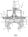
- a heating press (1) is equipped with mold segments (2, 3) which are arranged so that they can be positioned transversely to a longitudinal axis (5) in the region of a support (4).
- the mold segments (2, 3) have on the outside positioning bevels (6, 7) which cooperate correspondingly with associated adjusting bevels (8, 9) of an associated base plate (10).
- a positioning of the mold segments (2, 3) in the direction of the longitudinal axis (5) thereby leads to a forced positioning by the interaction of the positioning bevels (6, 7) and the adjusting bevels (8, 9).
- the carrier (4) is coupled to a hydraulic cylinder (11).
- a piston rod (12) of the hydraulic cylinder (11) extends at least partially through a guide tube (13).
- the hydraulic cylinder (11) is arranged such that it can rotate around the longitudinal axis (5) at least in regions.
- the carrier (4) is provided with mounting bolts (15) which engage with bolt heads (16) in fixing elements (17).
- the bolt heads (16) hereby provide mounting profiles which can be inserted into retaining recesses (18) of the fixing elements (17). In particular, it proves useful to provide the bolt heads (16) with a rounded contour and to introduce into rounded trough-like Garrungsausappelgeber (18).
- Arresting elements (27) arranged in the region of the fixing elements (17) can be positioned transversely to the longitudinal axis (5) of adjusting elements (19). In particular, it is thought to form the adjusting elements (19) as a pneumatic cylinder.
- Fig. 2 shows a side view of the in Fig. 1 shown upper part of the heating press (1).
- the hydraulic cylinder (11) and the pneumatic cylinder (14) fastened to the guide tube (13) can be seen.
- the guide tube (13) is arranged immovable relative to a press frame, so that a positioning movement of the pneumatic cylinder (14) causes a rotational movement of the hydraulic cylinder (11).
- other actuating elements can be used instead of the pneumatic cylinder (14).
- Fig. 3 shows an enlarged side view of the support pin (15).
- the support bolt (15) is provided with a rounded contoured bolt head (16) which is connected via a shaft (23) with a main body (24) of the support bolt (15).
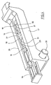
- Fig. 4 shows an enlarged perspective view of one of the fixing elements (17).
- the fixing element (17) has a frame (26) which carries the adjusting element (19) and a locking element (27). Using the adjusting element (19), the locking element (27) relative to the frame (26) is displaceable.
- the frame (26) is rotatably mounted via a pivot joint (28).
- the locking element (27) has two slots (29, 30) which are each provided with an insertion (31).
- the insertion recess (31) has a diameter which corresponds to at least one outer diameter of the bolt head (16).
- a width of the shank (23) of the support bolt (15) is slightly smaller than a width of the Slots (29, 30) dimensioned.
- the hydraulic cylinder (11) After this positioning of the locking elements (27) relative to the bolt heads (16), the hydraulic cylinder (11) is moved back to its original position and the springs (22) clamp the pressure plates (20, 21) relative to each other. Due to the coupling with the fixing elements (17), this also takes place Tensioning the Garrungsaus spiritept (18) relative to the bolt heads (16). The hydraulic cylinder (11) is then rotated using the pneumatic cylinder (14) in its working position and is available for opening and closing the mold segments (2, 3). Due to the tension is the mold is pressed against the hot plate.
- a lifting movement of the pressure plate (20) according to the embodiment in Fig. 2 be transferred to the adjusting elements (19) using hollow profiles (32).
- the adjusting elements (19) engage with end sections in the hollow profiles (32).
Landscapes
- Engineering & Computer Science (AREA)
- Mechanical Engineering (AREA)
- Moulds For Moulding Plastics Or The Like (AREA)
- Sheet Holders (AREA)
- Heating, Cooling, Or Curing Plastics Or The Like In General (AREA)
- Tyre Moulding (AREA)
Description
- Die Erfindung betrifft ein Verfahren zur Halterung einer Form einer Heizpresse für Reifen aus einem elastomeren Material, bei dem Formsegmente lösbar von einer Trageinrichtung gehaltert werden.
- Die Erfindung betrifft darüber hinaus eine Vorrichtung zur Halterung einer Form einer Heizpresse für Reifen aus einem elastomeren Material, bei der Formsegmente lösbar von einer Trageinrichtung gehaltert sind.
- Schließlich betrifft die Erfindung eine Heizpresse, die mit der vorstehend erwähnten Vorrichtung ausgestattet ist.
- Eine Heizpresse für Reifen besitzt typischerweise ein stationäres Sockelteil sowie ein gegenüber dem Sockelteil positionierbares Kopfteil. Am Kopfteil sind die Formhälften gehaltert. Die Formhälften sind quer zur Hubrichtung des Pressenkopfes positionierbar, um den Reifenrohling aufzunehmen und den fertig vulkanisierten Reifen wieder freizugeben. Nach einem vollständigen Öffnen der Form wird diese in vertikaler Richtung angehoben, um ein seitliches Entnehmen des fertigen Reifens zu unterstützen.
- Die verwendeten Formsegmente sind lösbar am Kopfteil der Presse angeordnet. Typischerweise erfolgt dies unter Verwendung eines Führungselementes, in dem die Formsegmente relativ zueinander positionierbar gelagert sind. Das Führungselement kann beispielsweise als ein sogenannter Container oder als ein C-artiges Profil ausgebildet sein, das zur Aufnahme von Schließkräften ausgebildet ist. Bei der Durchführung des vulkanisiervorganges wird das Führungselement typischerweise gegen eine Heizplatte gezogen, um eine entsprechende Temperierung zu unterstützen. Das Führungselement wird in der Regel unter Verwendung von Schrauben am Kopfteil der Presse fixiert. Bei einem Wechsel der Formsegmente müssen die in der Regel heißen Schrauben gelöst und dann die neuen Formsegmente wieder festgeschraubt werden. Die entsprechende Zeitdauer des Formwechselns führt zu einer entsprechenden Produktionsunterbrechung. Die Schrauben sind darüber hinaus häufig nur schlecht zugänglich.
- Aus der
EP 1 637 304 A ist bereits eine Heizpresse bekannt, bei der eine Form für die Reifen lösbar von einer Trageinrichtung gehaltert wird und bei der die Form aus Formsegmenten besteht. - Eine weitere Heizpresse mit lösbar von einer Trageinrichtung gehalterten Formsegmenten wird auch in der
JP 06029815 U - Aufgabe der vorliegenden Erfindung ist es, ein Verfahren der einleitend genannten Art derart zu verbessern, daß ein schnelles Formwechseln bei gleichzeitig hoher Betriebssicherheit unterstützt wird.
- Diese Aufgabe wird erfindungsgemäß dadurch gelöst, daß mit einem Halterungsprofil versehene Halterungsbolzen eines die Formsegmente lagernden Führungselementes durch eine Einführausnehmung eines im Bereich der Trageinrichtung angeordneten Fixierelementes hindurch geführt werden und daß anschließend ein Arretierelement des Fixierelementes quer zu einer Längsrichtung des Halterungsbolzens positioniert wird und daß das Halterungsprofil hierdurch gegenüber dem Fixierelement arretiert wird und daß vor der Durchführung der Querpositionierung des Arretierelementes ein das Fixierelement in Längsrichtung des Halterungsbolzens verstellendes Spannelement von einer Stelleinrichtung entgegen einer Federkraft verschoben und anschließend durch die Federkraft zurückgestellt wird, um das Halterungsprofil des Halterungsbolzens im Bereich des Fixierelementes durch Formschluß zu haltern.
- Weitere Aufgabe der vorliegenden Erfindung ist es, eine Vorrichtung der einleitend genannten Art derart zu gestalten, daß ein schnelles Formwechseln bei hoher Betriebssicherheit unterstützt wird.
- Diese Aufgabe wird erfindungsgemäß dadurch gelöst, daß mit einem Halterungsprofil versehene Halterungsbolzen eines die Formsegmente lagernden Führungselementes durch eine Einführausnehmung eines im Bereich der Trageinrichtung angeordneten Fixierelementes hindurchführbar sind und daß ein Arretierelement des Fixierelementes quer zu einer Längsrichtung des Halterungsbolzens positionierbar ist und daß das Halterungsprofil durch die Positionierung des Arretierelementes gegenüber dem Fixierelement arretierbar ist und daß das Fixierelement in Längsrichtung des Halterungsbolzens von einem Spannelement verstellbar ist und das Spannelement von einer Stelleinrichtung entgegen einer Federkraft mindestens einer Feder verschieblich und durch die Federkraft der Feder zurückstellbar angeordnet ist und daß in der zurückgestellten Positionierung das Halterungsprofil des Halterungsbolzens im Bereich des Fixierelementes durch Formschluß gehaltert ist.
- Durch den Eingriff der Halterungsbolzen in das Fixierelement ist es in einfacher Weise möglich, sowohl ein Arretieren als auch ein Entriegeln vorzunehmen. Nach einer Entspannung des Spannelementes braucht lediglich das Arretierelement des Fixierelementes verschoben zu werden, um die Halterungsbolzen entweder zu fixieren oder freizugeben.
- Die vorliegende Erfindung ermöglicht es insbesondere, die Durchführung der Hubbewegung zum Anheben der geöffneten Form, die Verspannung der Formen zwischen der Heizplatte und dem Pressensockel und die Durchführung einer Entspannung im Bereich der Fixierelemente vor einem Lösen der Halterungsbolzen über ein gemeinsames Stellelement, typischerweise einen Hydraulikzylinder, durchzuführen. Es wird hierdurch ein einfacher und betriebssicherer Grundaufbau bereitgestellt.
- Durch die Realisierung der vorliegenden Erfindung wird die gemäß dem Stand der Technik zur lösbaren Halterung der Formsegmente erforderliche zusätzliche Formadapterplatte bzw. zusätzliche Pneumatikzylinder oder zusätzliche Hydraulikzylinder vermieden. Darüber hinaus wird das Auftreten eines Spaltes zwischen der verwendeten Heizplatte und der Form vermieden und es können bei einer geeigneten Gestaltung des Fixierelementes Befestigungen mit unterschiedlichen Halteelementen ausgestellter Formen ermöglicht werden. Es liegt somit keine Beschränkung auf einen einzigen fest vorgegebenen Formbefestigungslochkreis vor.
- Eine Verwendung des Hauptzylinders der Heizpresse und somit die Vermeidung eines zusätzlichen Stellelementes wird dadurch ermöglicht, daß die Stelleinrichtung für das Spannelemente hydraulisch angetrieben wird.
- Zwei unterschiedliche Arbeitspositionierungen für den Hydraulikzylinder können dadurch vorgegeben werden, daß die Stelleinrichtung vor einer Verspannung des Spannelementes um ihre Längsachse herum verdreht wird.
- Eine einfache Positionierung wird dadurch unterstützt, daß die Drehbewegung von einem Pneumatikzylinder vorgegeben wird.
- Eine einfache Durchführung des Verriegelungsvorganges sowie eines Entriegelungsvorganges wird dadurch ermöglicht, daß das Arretierelement des Fixierelementes von einem Pneumatikzylinder verstellt wird.
- Eine zuverlässige Halterung der Formsegmente sowie ein wirksames verspannen gegenüber einer Heizplatte werden dadurch unterstützt, daß eine Mehrzahl von Fixierelementen relativ zueinander beabstandet und mit ihren jeweiligen Längsachsen in einer radialen Richtung auf einer Längsachse der Stelleinrichtung ausgerichtet werden.
- Eine gleichmäßige Krafteinleitung wird dadurch ermöglicht, daß die Fixierelemente bezüglich der Längsachse in einer Umfangsrichtung relativ zueinander im wesentlichen äquidistant angeordnet werden.
- Eine kompakte Konstruktion der Arretierungselemente wird dadurch unterstützt, daß das Arretierelement von einem pneumatischen Antrieb positioniert wird.
- Eine robuste und mechanisch stabile Konstruktion wird dadurch erreicht, daß der Halterungsbolzen bei einer Positionierung des Arretierelementes mit einem Schaft innerhalb eines Schlitzes des Arretierelementes positioniert wird.
- Eine verschleißarme Übertragung hoher Spannkräfte wird dadurch erleichtert, daß entlang des Schlitzes mindestens eine an den Bolzenkopf angepaßte Halterungsausnehmung positioniert wird.
- Eine zuverlässige Arretierung kann dadurch gewährleistet werden, daß eine Arretierungspositionierung von mindestens einem Sicherheitsschalter überwacht wird.
- Zur Bereitstellung unterschiedlicher Formbefestigungslochkreise wird vorgeschlagen, daß durch eine Positionierung des Arretierelementes mindestens zwei unterschiedliche Verriegelungspositionen vorgebbar sind.
- In den Zeichnungen sind Ausführungsbeispiele der Erfindung schematisch dargestellt. Es zeigen:
- Fig. 1
- einen Vertikalschnitt durch eine teilweise dargestellte Reifenheizpresse,
- Fig. 2
- eine Seitenansicht des oberen Pressenteiles gemäß
Fig. 1 , - Fig. 3
- eine vergrößerte Seitenansicht eines verriegelungsbolzens,
- Fig. 4
- eine perspektivische Darstellung eines Fixierelementes und
- Fig. 5
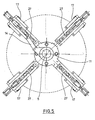
- eine Draufsicht auf
Fig. 4 mit in einer radialen Richtung äquidistant angeordneten Fixierelementen. - Gemäß der Ausführungsform in
Fig. 1 ist eine Heizpresse (1) mit Formsegmenten (2, 3) ausgestattet, die im Bereich eines Trägers (4) quer zu einer Längsachse (5) positionierbar angeordnet sind. Die Formsegmente (2, 3) weisen außenseitig Positionierschrägen (6, 7) auf, die korrespondierend mit zugeordneten Stellschrägen (8, 9) einer zugeordneten Grundplatte (10) zusammenwirken. Eine Positionierung der Formsegmente (2, 3) in Richtung der Längsachse (5) führt hierdurch zu einer Zwangspositionierung durch das Zusammnenwirken der Positionierschrägen (6, 7) und der Stellschrägen (8, 9). - Zur Durchführung der Positionierbewegung ist der Träger (4) mit einem Hydraulikzylinder (11) gekoppelt. Eine Kolbenstange (12) des Hydraulikzylinders (11) erstreckt sich wenigstens bereichsweise durch ein Führungsrohr (13) hindurch. Unter Verwendung eines Pneumatikzylinders (14) ist der Hydraulikzylinder (11) zumindest bereichsweise um die Längsachse (5) herum verdrehbar angeordnet.
- Der Träger (4) ist mit Halterungsbolzen (15) versehen, die mit Bolzenköpfen (16) in Fixierelemente (17) eingreifen. Die Bolzenköpfe (16) stellen hierbei Halterungsprofile bereit, die in Halterungsausnehmungen (18) der Fixierelemente (17) einführbar sind. Insbesondere erweist es sich als zweckmäßig, die Bolzenköpfe (16) mit einer gerundeten Kontur zu versehen und in gerundete muldenartige Halterungsausnehmungen (18) einzuführen.
- Im Bereich der Fixierelemente (17) angeordnete Arretierelemente (27) sind quer zur Längsachse (5) von Stellelementen (19) positionierbar. Insbesondere ist daran gedacht, die Stellelemente (19) als Pneumatikzylinder auszubilden.
-
Fig. 2 zeigt eine Seitenansicht des inFig. 1 dargestellten oberen Teiles der Heizpresse (1). Zu erkennen ist insbesondere der Hydraulikzylinder (11) sowie der am Führungsrohr (13) befestigte Pneumatikzylinder (14). Das Führungsrohr (13) ist relativ zu einem Pressengestell unbeweglich angeordnet, so daß eine Positionierbewegung des Pneumatikzylinders (14) eine Drehbewegung des Hydraulikzylinders (11) verursacht. Grundsätzlich können statt des Pneumatikzylinders (14) auch andere Stellelemente verwendet werden. - Zwischen zwei Andruckplatten (20, 21) sind Federn (22) angeordnet, die unter Verwendung des Hydraulikzylinders (11) gespannt oder entspannt werden-können.
-
Fig. 3 zeigt eine vergrößerte Seitenansicht des Halterungsbolzens (15). Der Halterungsbolzen (15) ist mit einem gerundet konturierten Bolzenkopf (16) versehen, der über einen Schaft (23) mit einem Hauptkörper (24) des Halterungsbolzens (15) verbunden ist. Über ein Außengewinde (25) kann der Halterungsbolzen (15) im Bereich der Grundplatte (10) fixiert werden. -
Fig. 4 zeigt eine vergrößerte perspektivische Darstellung eines der Fixierelemente (17). Das Fixierelement (17) weist einen Rahmen (26) auf, der das Stellelement (19) sowie ein Arretierelement (27) trägt. Unter Verwendung des Stellelementes (19) ist das Arretierelement (27) relativ zum Rahmen (26) verschieblich. Der Rahmen (26) ist über ein Schwenkgelenk (28) drehbeweglich gelagert. - Aus
Fig. 4 ist zu erkennen, daß die Halterungsausnehmungen (18) im Bereich des Arretierelementes (27) angeordnet sind. Beim dargestellten Ausführungsbeispiel weist das Arretierelement (27) zwei Schlitze (29, 30) auf, die jeweils mit einer Einführausnehmung (31) versehen sind. Die Einführausnehmung (31) weist einen Durchmesser auf, der mindestens einem Außendurchmesser des Bolzenkopfes (16) entspricht. Eine Breite des Schaftes (23) des Halterungsbolzens (15) ist etwas geringer als eine Breite der Schlitze (29, 30) dimensioniert. Gemäß dem Ausführungsbeispielen inFig. 4 sind im Bereich jedes der Schlitze (29, 30) zwei Halterungsausnehmungen (18) angeordnet. - Zur Durchführung eines Arretiervorganges wird zunächst der Halterungsbolzen (15) mit seinem Bolzenkopf (16) durch die Einführausnehmungen (31) hindurch geführt. Anschließend erfolgt eine Querpositionierung des Arretierelementes (27) derart, daß der Bolzenkopf (16) im Bereich einer der Halterungsausnehmungen (18) angeordnet ist. In diesem Zustand wird das Fixierelement (17) relativ zum Bolzenkopf (16) verspannt. Eine Entriegelung erfolgt in umgekehrter Reihenfolge.
- Gemäß der Ausführungsform in
Fig. 5 sind bezüglich der Längsachse (5) in einer Umfangsrichtung (4) Fixierelemente (17) relativ zueinander im wesentlichen äquidistant angeordnet. Zu erkennen ist ebenfalls der Pneumatikzylinder (14) zur Verstellung des Hydraulikzylinders (11). - Nachfolgend wird die Funktion der Verriegelung näher erläutert. Bei einem Schließen der Heizpresse (1) fahren die Halterungsbolzen (15) mit ihren Bolzenköpfen (16) durch die Einführausnehmungen (31) der Fixierelemente (17) hindurch. Anschließend wird das Arretierelement (27) unter Verwendung des Stellelementes (19) bezüglich der Längsachse (5) in einer radialen Richtung verschoben, so daß die Halterungsausnehmung (18) im Bereich des kugelartigen Bolzenkopfes (16) positioniert ist und hierdurch den Bolzenkopf (16) blockiert. Das Erreichen einer Verriegelungsposition des Arretierelementes (27) kann unter Verwendung von Sicherheitsschaltern abgefragt werden. Die Anzahl der vorgesehenen Halterungsausnehmungen (18) definiert die Anzahl der möglichen Befestigungslochkreise.
- Nach dieser Positionierung der Arretierelemente (27) relativ zu den Bolzenköpfen (16) wird der Hydraulikzylinder (11) in seine Ausgangslage zurückgefahren und die Federn (22) verspannen die Andruckplatten (20, 21) relativ zueinander. Aufgrund der Kopplung mit den Fixierelementen (17) erfolgt hierdurch auch eine Verspannung der Halterungsausnehmungen (18) relativ zu den Bolzenköpfen (16). Der Hydraulikzylinder (11) wird anschließend unter Verwendung des Pneumatikzylinders (14) in seiner Arbeitsposition gedreht und steht zum Öffnen und Schließen der Formsegmente (2, 3) zur Verfügung. Aufgrund der erfolgten Verspannung wird die Form gegen die Heizplatte gepreßt.
- Eine Hubbewegung der Andruckplatte (20) kann gemäß der Ausführungsform in
Fig. 2 unter Verwendung von Hohlprofilen (32) auf die Stellelemente (19) übertragen werden. Die Stellelemente (19) greifen hierbei mit Endabschnitten in die Hohlprofile (32) ein. - Durch das Verdrehen des Hydraulikzylinders (11) unter Verwendung des Pneumatikzylinders (14) ist es möglich, den Hydraulikzylinder (11) nach einem Verdrehen über entsprechende Kopplungsprofile auf die obere Andruckplatte (20) einwirken zu lassen und bei einer anschließenden Hubbewegung die Andruckplatte (20) gegen die Andruckplatte (21) zu verschieben und hierdurch die Federn (22) zu spannen und gleichzeitig die Fixierelemente (17) um die Schwenkgelenke (28) herum in Richtung auf die Heizplatte zu verschwenken. Nach einem Abschluß des Verriegelungsvorganges und nach einem zurückfahren des Hydraulikzylinders (11) führen die Federn (22) ohne weitere äußere Einwirkung die erforderliche Verspannung durch. Nach einem Zurückdrehen des Hydraulikzylinders (11) in die Arbeitsposition liegt kein weiterer Formschluß mit der Andruckplatte (20) vor, so daß das Öffnen und Schließen der Heizpresse (1) in üblicher Weise durchgeführt werden kann.
Claims (24)
- Verfahren zur Halterung einer Form einer Heizpresse (1) für Reifen aus einem elastomeren Material, bei dem Formsegmente (2, 3) lösbar von einer Trageinrichtung gehaltert werden, dadurch gekennzeichnet, daß mit einem Halterungsprofil versehene Halterungsbolzen (15) eines die Formsegmente (2, 3) lagernden Führungselementes durch eine Einführausnehmung (31) eines im Bereich der Trageinrichtung angeordneten Fixierelementes (17) hindurch geführt werden und daß anschließend ein Arretierelement (27) des Fixierelementes (17) quer zu einer Längsrichtung des Halterungsbolzens (15) positioniert wird und daß das Halterungsprofil hierdurch gegenüber dem Fixierelement (17) arretiert wird und daß vor der Durchführung der Querpositionierung des Arretierelementes (27) ein das Fixierelement (17) in Längsrichtung des Halterungsbolzens verstellendes Spannelement von einer Stelleinrichtung entgegen einer Federkraft (22) verschoben und anschließend durch die Federkraft (22) zurückgestellt wird, um das Halterungsprofil des Halterungsbolzens (15) im Bereich des Fixierelementes (17) durch Formschluß zu haltern.
- Verfahren nach Anspruch 1, dadurch gekennzeichnet, daß die Stelleinrichtung für das Spannelemente hydraulisch angetrieben wird.
- Verfahren nach Anspruch 1 oder 2, dadurch gekennzeichnet, daß die Stelleinrichtung vor einer Verspannung des Spannelementes um ihre Längsachse herum verdreht wird.
- Verfahren nach Anspruch 3, dadurch gekennzeichnet, daß die Drehbewegung von einem Pneumatikzylinder vorgegeben wird.
- Verfahren nach einem der Ansprüche 1 bis 4, dadurch gekennzeichnet, daß das Arretierelement (27) des Fixierelementes (17) von einem Pneumatikzylinder verstellt wird.
- Verfahren nach einem der Ansprüche 1 bis 5, dadurch gekennzeichnet, daß eine Mehrzahl von Fixierelementen (17) relativ zueinander beabstandet und mit ihren jeweiligen Längsachsen in einer radialen Richtung auf eine Längsachse der Stelleinrichtung ausgerichtet werden.
- Verfahren nach Anspruch 6, dadurch gekennzeichnet, daß die Fixierelemente bezüglich der Längsachse in einer Umfangsrichtung relativ zueinander im wesentlichen äquidistant angeordnet werden.
- Verfahren nach einem der Ansprüche 1 bis 7, dadurch gekennzeichnet, daß das Arretierelement (27) von einem pneumatischen Antrieb positioniert wird.
- Verfahren nach einem der Ansprüche 1 bis 8, dadurch gekennzeichnet, daß der Halterungsbolzen (15) bei einer Positionierung des Arretierelementes (27) mit einem Schaft (23) innerhalb eines Schlitzes (29, 30) des Arretierelementes (27) positioniert wird.
- Verfahren nach einem der Ansprüche 1 bis 9, dadurch gekennzeichnet, daß entlang des Schlitzes (29, 30) mindestens eine an den Bolzenkopf (16) angepaßte Halterungsausnehmung (18) positioniert wird.
- Verfahren nach einem der Ansprüche 1 bis 10, dadurch gekennzeichnet, daß eine Arretierungspositionierung von mindestens einem Sicherheitsschalter überwacht wird.
- Verfahren nach einem der Ansprüche 1 bis 11, dadurch gekennzeichnet, daß durch eine Positionierung des Arretierelementes (27) mindestens zwei unterschiedliche Verriegelungspositionen vorgebbar sind.
- Vorrichtung zur Halterung einer Form einer Heizpresse (1) für Reifen aus einem elastomeren Material, bei der Formsegmente (2, 3) lösbar von einer Trageinrichtung gehaltert sind, dadurch gekennzeichnet, daß mit einem Halterungsprofil versehene Halterungsbolzen (15) eines die Formsegmente (2, 3) lagernden Führungselementes durch eine Einführausnehmung (31) eines im Bereich der Trageinrichtung angeordneten Fixierelementes (17) hindurchführbar sind und daß ein Arretierelement (27) des Fixierelementes (17) quer zu einer Längsrichtung des Halterungsbolzens (15) positionierbar ist und daß das Halterungsprofil durch die Positionierung des Arretierelementes (27) gegenüber dem Fixierelement (17) arretierbar ist und daß das Fixierelement (17) in Längsrichtung des Halterungsbolzens (15) von einem Spannelement verstellbar ist und das Spannelement von einer Stelleinrichtung entgegen einer Federkraft mindestens einer Feder (22) verschieblich und durch die Federkraft der Feder zurückstellbar angeordnet ist und daß in der zurückgestellten Positionierung das Halterungsprofil des Halterungsbolzens (15) im Bereich des Fixierelementes (17) durch Formschluß gehaltert ist.
- Vorrichtung nach Anspruch 13, dadurch gekennzeichnet, daß die Stelleinrichtung für das Spannelement als ein Hydraulikzylinder ausgebildet ist.
- Vorrichtung nach Anspruch 13 oder 14, dadurch gekennzeichnet, daß der Hydraulikzylinder relativ zu einer Längsachse verdrehbar angeordnet ist.
- Vorrichtung nach einem der Ansprüche 13 bis 15, dadurch gekennzeichnet, daß zur Verdrehung des Hydraulikzylinders (11) ein Pneumatikzylinder (14) verwendet ist.
- Vorrichtung nach einem der Ansprüche 13 bis 16, dadurch gekennzeichnet, daß das Arretierelement (27) mit einem Positionierelement gekoppelt ist.
- Vorrichtung nach einem der Ansprüche 13 bis 17, dadurch gekennzeichnet, daß mehrere Fixierelemente (17) mit ihren jeweiligen Längsachsen in einer radialen Richtung auf eine Längsachse des Hydraulikzylinders (11) ausgerichtet sind.
- Vorrichtung nach einem der Ansprüche 13 bis 18, dadurch gekennzeichnet, daß die Fixierelemente (17) bezüglich der Längsachse des Hydraulikzylinders (11) in einer Umfangsrichtung im wesentlichen äquidistant relativ zueinander angeordnet sind.
- Vorrichtung nach einem der Ansprüche 13 bis 19, dadurch gekennzeichnet, daß das Positionierelement für das Arretierelement (27) als ein Pneumatikzylinder ausgebildet ist.
- Vorrichtung nach einem der Ansprüche 13 bis 20, dadurch gekennzeichnet, daß das Arretierelement (27) mindestens einen Schlitz (29, 30) aufweist, in den eine Einführausnehmung (31) einmündet und entlang dessen mindestens eine Halterungsausnehmung (18) für den Bolzenkopf (16) angeordnet ist.
- Vorrichtung nach einem der Ansprüche 13 bis 21, dadurch gekennzeichnet, daß der Bolzenkopf (16) mindestens bereichsweise gerundet ausgebildet und an eine gerundete muldenförmige Kontur der Halterungsausnehmung (18) angepaßt ist.
- Vorrichtung nach einem der Ansprüche 13 bis 22, dadurch gekennzeichnet, daß das Arretierelement (27) mit mindestens einem Sicherheitsschalter gekoppelt ist.
- Vorrichtung nach einem der Ansprüche 13 bis 23, dadurch gekennzeichnet, daß das Arretierelement (27) mindestens zwei unterschiedliche Arretierpositionen aufweist.
Priority Applications (2)
| Application Number | Priority Date | Filing Date | Title |
|---|---|---|---|
| PL09716808T PL2254738T3 (pl) | 2008-03-04 | 2009-03-04 | Sposób i urządzenie do mocowania form |
| SI200930172T SI2254738T1 (sl) | 2008-03-04 | 2009-03-04 | Postopek in naprava za drĺ˝anje kalupov |
Applications Claiming Priority (2)
| Application Number | Priority Date | Filing Date | Title |
|---|---|---|---|
| DE102008012850 | 2008-03-04 | ||
| PCT/DE2009/000320 WO2009109184A2 (de) | 2008-03-04 | 2009-03-04 | Verfahren und vorrichtung zur halterung von formen |
Publications (2)
| Publication Number | Publication Date |
|---|---|
| EP2254738A2 EP2254738A2 (de) | 2010-12-01 |
| EP2254738B1 true EP2254738B1 (de) | 2011-11-23 |
Family
ID=40936565
Family Applications (1)
| Application Number | Title | Priority Date | Filing Date |
|---|---|---|---|
| EP09716808A Not-in-force EP2254738B1 (de) | 2008-03-04 | 2009-03-04 | Verfahren und vorrichtung zur halterung von formen |
Country Status (10)
| Country | Link |
|---|---|
| US (1) | US20110086123A1 (de) |
| EP (1) | EP2254738B1 (de) |
| CN (1) | CN102015238B (de) |
| AT (1) | ATE534499T1 (de) |
| DE (1) | DE102009012191B4 (de) |
| ES (1) | ES2378519T3 (de) |
| PL (1) | PL2254738T3 (de) |
| PT (1) | PT2254738E (de) |
| SI (1) | SI2254738T1 (de) |
| WO (1) | WO2009109184A2 (de) |
Families Citing this family (5)
| Publication number | Priority date | Publication date | Assignee | Title |
|---|---|---|---|---|
| FR2951401B1 (fr) * | 2009-10-20 | 2016-12-30 | Soc De Tech Michelin | Presse de vulcanisation |
| CN102990833B (zh) * | 2012-12-21 | 2015-05-06 | 株式会社普利司通 | 轮胎定型硫化机活络模操纵装置 |
| EP2956293B1 (de) | 2013-02-18 | 2020-02-05 | Harburg-Freudenberger Maschinenbau GmbH | Vorrichtung und verfahren zum justieren der höhe einer form einer reifenheizpresse sowie reifenheizpresse |
| DE102018000973A1 (de) | 2017-02-06 | 2018-08-09 | Harburg-Freudenberger Maschinenbau Gmbh | Vorrichtung zum Vulkanisieren von Reifen |
| CN114434692B (zh) * | 2020-11-05 | 2025-02-07 | 张再顺 | 用于成型机的快速换模装置 |
Family Cites Families (14)
| Publication number | Priority date | Publication date | Assignee | Title |
|---|---|---|---|---|
| DE7206606U (de) * | 1972-10-19 | Dunlop Ag | Preßform zum Vulkanisieren von Reifen | |
| US2567985A (en) * | 1946-03-30 | 1951-09-18 | Harold L Baker | Recapping and retreading mold |
| US3581535A (en) * | 1968-07-11 | 1971-06-01 | Goodyear Tire & Rubber | Method and apparatus for making blades |
| DE2047074A1 (en) * | 1970-09-24 | 1972-03-30 | Johann IhIe Vulkanisier Betrieb 8870 Gunzburg | Vulcanising mounting - using a jaw chuck to grip the tyre at equal segments of arc |
| GB1371821A (en) * | 1971-06-01 | 1974-10-30 | Goodyear Tire & Rubber | Tyre mould apparatus |
| DE3400592A1 (de) * | 1984-01-10 | 1985-07-18 | A-Z Formen- und Maschinenbau GmbH, 8000 München | Vorrichtung zum heizpressen von fahrzeugreifen |
| US4773839A (en) * | 1987-02-05 | 1988-09-27 | Amoco Corporation | Quick-change thermoformer |
| JPH0629815U (ja) | 1992-09-25 | 1994-04-19 | 株式会社神戸製鋼所 | タイヤ加硫機のモールドクランプ装置 |
| JPH0847928A (ja) * | 1994-06-03 | 1996-02-20 | Mitsubishi Heavy Ind Ltd | タイヤ加硫用割金型装置 |
| EP0712704A3 (de) * | 1994-11-16 | 1996-11-13 | Mitsubishi Heavy Ind Ltd | Formenanordnung zum Vulkanisieren von Reifen |
| JP3272574B2 (ja) * | 1995-07-20 | 2002-04-08 | 三菱重工業株式会社 | タイヤ加硫用金型組立体の金型クランプ装置 |
| US5866170A (en) * | 1996-06-06 | 1999-02-02 | Kabushiki Kaisha Kobe Seiko Sho | Tire press |
| US5773041A (en) * | 1997-06-11 | 1998-06-30 | Mcneil & Nrm, Inc. | Mold clamping system |
| JP4291612B2 (ja) * | 2003-04-25 | 2009-07-08 | Hirotek株式会社 | タイヤ加硫機におけるモールド着脱装置 |
-
2009
- 2009-03-04 US US12/920,902 patent/US20110086123A1/en not_active Abandoned
- 2009-03-04 EP EP09716808A patent/EP2254738B1/de not_active Not-in-force
- 2009-03-04 DE DE102009012191.9A patent/DE102009012191B4/de not_active Expired - Fee Related
- 2009-03-04 CN CN2009801144604A patent/CN102015238B/zh not_active Expired - Fee Related
- 2009-03-04 AT AT09716808T patent/ATE534499T1/de active
- 2009-03-04 PL PL09716808T patent/PL2254738T3/pl unknown
- 2009-03-04 PT PT09716808T patent/PT2254738E/pt unknown
- 2009-03-04 ES ES09716808T patent/ES2378519T3/es active Active
- 2009-03-04 SI SI200930172T patent/SI2254738T1/sl unknown
- 2009-03-04 WO PCT/DE2009/000320 patent/WO2009109184A2/de not_active Ceased
Also Published As
| Publication number | Publication date |
|---|---|
| US20110086123A1 (en) | 2011-04-14 |
| EP2254738A2 (de) | 2010-12-01 |
| DE102009012191B4 (de) | 2018-04-26 |
| ATE534499T1 (de) | 2011-12-15 |
| WO2009109184A3 (de) | 2009-11-12 |
| PL2254738T3 (pl) | 2012-06-29 |
| SI2254738T1 (sl) | 2012-06-29 |
| ES2378519T3 (es) | 2012-04-13 |
| CN102015238A (zh) | 2011-04-13 |
| CN102015238B (zh) | 2013-07-24 |
| WO2009109184A2 (de) | 2009-09-11 |
| PT2254738E (pt) | 2012-02-14 |
| DE102009012191A1 (de) | 2009-09-10 |
Similar Documents
| Publication | Publication Date | Title |
|---|---|---|
| DE3785306T2 (de) | Reifenvulkanisierpresse. | |
| DE102009012191B4 (de) | Verfahren und Vorrichtung zur Halterung von Formen | |
| DE19606568A1 (de) | Vorrichtung und Verfahren zum Spannen einer Spritzgießform | |
| DE2246951A1 (de) | Luftreifen-formpresse und luftreifenvulkanisierpresse - zentrierungsmechanismus und beschickungsverfahren | |
| WO1979000704A1 (fr) | Procede et dispositif pour le vissage de manchons tubulaires | |
| DE102008008122A1 (de) | Innenhochdruckumformwerkzeug-Rohrabdichtungsanordnung | |
| DE102011084110B4 (de) | Mehrschicht-Strangpresse | |
| EP2243615B1 (de) | Spritzgiessmaschine | |
| DE4024435A1 (de) | Zentralmechanismus einer reifenvulkanisiermaschine | |
| WO2013072459A2 (de) | Verriegelungsvorrichtung für holme einer kunststoffverarbeitungsmaschine | |
| DE68923682T2 (de) | Klemmvorrichtung des Oberteils einer Metallform einer Reifenvulkanisiermaschine. | |
| DE2751036A1 (de) | Presse fuer reifenvulkanisierformen | |
| DE2542015C3 (de) | Verriegelungseinrichtung an einer Blasformeinheit für eine Kunststoffblasmaschine | |
| EP0687540A1 (de) | Aufspannvorrichtung | |
| DE3335329A1 (de) | Werkzeugmaschine, insbesondere revolverschneidpresse mit fuer einen ferngesteuerten wechsel geeigneter werkzeugaufnahme | |
| EP1487626B1 (de) | Formschliesseinheit mit einer formhöhenverstellung sowie verfahren zu deren betätigung | |
| DE3140837C2 (de) | Druckgießmaschine | |
| DE4122567C2 (de) | ||
| DE4139861C2 (de) | Blaseneinspanneinheit für eine Reifenvulkanisiermaschine | |
| EP0313035A2 (de) | Schliesseinheit für eine Spritzgiessmaschine | |
| DE102011015943B4 (de) | Verriegelungsvorrichtung für Säulen einer Kunststoffverarbeitungsmaschine | |
| DE4025310C2 (de) | ||
| DE10122961A1 (de) | Verriegelungsvorrichtung für eine axial verstellbare Spindel | |
| DE2332205A1 (de) | Vorrichtung zur optimierung des einund ausbaues von spritzgiesswerkzeugen bei der verarbeitung von kunststoffen oder gleichartigen materialien auf spritzgiessmaschinen | |
| DE102006034919A1 (de) | Spritzgießmaschine |
Legal Events
| Date | Code | Title | Description |
|---|---|---|---|
| PUAI | Public reference made under article 153(3) epc to a published international application that has entered the european phase |
Free format text: ORIGINAL CODE: 0009012 |
|
| 17P | Request for examination filed |
Effective date: 20100901 |
|
| AK | Designated contracting states |
Kind code of ref document: A2 Designated state(s): AT BE BG CH CY CZ DE DK EE ES FI FR GB GR HR HU IE IS IT LI LT LU LV MC MK MT NL NO PL PT RO SE SI SK TR |
|
| AX | Request for extension of the european patent |
Extension state: AL BA RS |
|
| DAX | Request for extension of the european patent (deleted) | ||
| GRAP | Despatch of communication of intention to grant a patent |
Free format text: ORIGINAL CODE: EPIDOSNIGR1 |
|
| GRAS | Grant fee paid |
Free format text: ORIGINAL CODE: EPIDOSNIGR3 |
|
| GRAA | (expected) grant |
Free format text: ORIGINAL CODE: 0009210 |
|
| AK | Designated contracting states |
Kind code of ref document: B1 Designated state(s): AT BE BG CH CY CZ DE DK EE ES FI FR GB GR HR HU IE IS IT LI LT LU LV MC MK MT NL NO PL PT RO SE SI SK TR |
|
| REG | Reference to a national code |
Ref country code: GB Ref legal event code: FG4D Free format text: NOT ENGLISH |
|
| REG | Reference to a national code |
Ref country code: CH Ref legal event code: EP |
|
| REG | Reference to a national code |
Ref country code: IE Ref legal event code: FG4D Free format text: LANGUAGE OF EP DOCUMENT: GERMAN |
|
| REG | Reference to a national code |
Ref country code: DE Ref legal event code: R096 Ref document number: 502009002008 Country of ref document: DE Effective date: 20120119 |
|
| REG | Reference to a national code |
Ref country code: RO Ref legal event code: EPE |
|
| REG | Reference to a national code |
Ref country code: PT Ref legal event code: SC4A Free format text: AVAILABILITY OF NATIONAL TRANSLATION Effective date: 20120206 |
|
| REG | Reference to a national code |
Ref country code: NL Ref legal event code: T3 |
|
| REG | Reference to a national code |
Ref country code: ES Ref legal event code: FG2A Ref document number: 2378519 Country of ref document: ES Kind code of ref document: T3 Effective date: 20120413 |
|
| LTIE | Lt: invalidation of european patent or patent extension |
Effective date: 20111123 |
|
| PG25 | Lapsed in a contracting state [announced via postgrant information from national office to epo] |
Ref country code: LT Free format text: LAPSE BECAUSE OF FAILURE TO SUBMIT A TRANSLATION OF THE DESCRIPTION OR TO PAY THE FEE WITHIN THE PRESCRIBED TIME-LIMIT Effective date: 20111123 Ref country code: NO Free format text: LAPSE BECAUSE OF FAILURE TO SUBMIT A TRANSLATION OF THE DESCRIPTION OR TO PAY THE FEE WITHIN THE PRESCRIBED TIME-LIMIT Effective date: 20120223 Ref country code: IS Free format text: LAPSE BECAUSE OF FAILURE TO SUBMIT A TRANSLATION OF THE DESCRIPTION OR TO PAY THE FEE WITHIN THE PRESCRIBED TIME-LIMIT Effective date: 20120323 |
|
| PG25 | Lapsed in a contracting state [announced via postgrant information from national office to epo] |
Ref country code: LV Free format text: LAPSE BECAUSE OF FAILURE TO SUBMIT A TRANSLATION OF THE DESCRIPTION OR TO PAY THE FEE WITHIN THE PRESCRIBED TIME-LIMIT Effective date: 20111123 Ref country code: SE Free format text: LAPSE BECAUSE OF FAILURE TO SUBMIT A TRANSLATION OF THE DESCRIPTION OR TO PAY THE FEE WITHIN THE PRESCRIBED TIME-LIMIT Effective date: 20111123 Ref country code: HR Free format text: LAPSE BECAUSE OF FAILURE TO SUBMIT A TRANSLATION OF THE DESCRIPTION OR TO PAY THE FEE WITHIN THE PRESCRIBED TIME-LIMIT Effective date: 20111123 Ref country code: GR Free format text: LAPSE BECAUSE OF FAILURE TO SUBMIT A TRANSLATION OF THE DESCRIPTION OR TO PAY THE FEE WITHIN THE PRESCRIBED TIME-LIMIT Effective date: 20120224 |
|
| REG | Reference to a national code |
Ref country code: IE Ref legal event code: FD4D |
|
| PG25 | Lapsed in a contracting state [announced via postgrant information from national office to epo] |
Ref country code: CY Free format text: LAPSE BECAUSE OF FAILURE TO SUBMIT A TRANSLATION OF THE DESCRIPTION OR TO PAY THE FEE WITHIN THE PRESCRIBED TIME-LIMIT Effective date: 20111123 |
|
| REG | Reference to a national code |
Ref country code: PL Ref legal event code: T3 |
|
| REG | Reference to a national code |
Ref country code: SK Ref legal event code: T3 Ref document number: E 11516 Country of ref document: SK |
|
| REG | Reference to a national code |
Ref country code: HU Ref legal event code: AG4A Ref document number: E013430 Country of ref document: HU |
|
| PG25 | Lapsed in a contracting state [announced via postgrant information from national office to epo] |
Ref country code: DK Free format text: LAPSE BECAUSE OF FAILURE TO SUBMIT A TRANSLATION OF THE DESCRIPTION OR TO PAY THE FEE WITHIN THE PRESCRIBED TIME-LIMIT Effective date: 20111123 Ref country code: EE Free format text: LAPSE BECAUSE OF FAILURE TO SUBMIT A TRANSLATION OF THE DESCRIPTION OR TO PAY THE FEE WITHIN THE PRESCRIBED TIME-LIMIT Effective date: 20111123 Ref country code: BG Free format text: LAPSE BECAUSE OF FAILURE TO SUBMIT A TRANSLATION OF THE DESCRIPTION OR TO PAY THE FEE WITHIN THE PRESCRIBED TIME-LIMIT Effective date: 20120223 Ref country code: IE Free format text: LAPSE BECAUSE OF FAILURE TO SUBMIT A TRANSLATION OF THE DESCRIPTION OR TO PAY THE FEE WITHIN THE PRESCRIBED TIME-LIMIT Effective date: 20111123 |
|
| PLBE | No opposition filed within time limit |
Free format text: ORIGINAL CODE: 0009261 |
|
| STAA | Information on the status of an ep patent application or granted ep patent |
Free format text: STATUS: NO OPPOSITION FILED WITHIN TIME LIMIT |
|
| BERE | Be: lapsed |
Owner name: HARBURG-FREUDENBERGER MASCHINENBAU G.M.B.H. Effective date: 20120331 |
|
| 26N | No opposition filed |
Effective date: 20120824 |
|
| PG25 | Lapsed in a contracting state [announced via postgrant information from national office to epo] |
Ref country code: MC Free format text: LAPSE BECAUSE OF NON-PAYMENT OF DUE FEES Effective date: 20120331 |
|
| REG | Reference to a national code |
Ref country code: FR Ref legal event code: ST Effective date: 20121130 |
|
| REG | Reference to a national code |
Ref country code: DE Ref legal event code: R097 Ref document number: 502009002008 Country of ref document: DE Effective date: 20120824 |
|
| PG25 | Lapsed in a contracting state [announced via postgrant information from national office to epo] |
Ref country code: FR Free format text: LAPSE BECAUSE OF NON-PAYMENT OF DUE FEES Effective date: 20120402 Ref country code: BE Free format text: LAPSE BECAUSE OF NON-PAYMENT OF DUE FEES Effective date: 20120331 |
|
| PG25 | Lapsed in a contracting state [announced via postgrant information from national office to epo] |
Ref country code: MK Free format text: LAPSE BECAUSE OF FAILURE TO SUBMIT A TRANSLATION OF THE DESCRIPTION OR TO PAY THE FEE WITHIN THE PRESCRIBED TIME-LIMIT Effective date: 20111123 |
|
| PG25 | Lapsed in a contracting state [announced via postgrant information from national office to epo] |
Ref country code: MT Free format text: LAPSE BECAUSE OF FAILURE TO SUBMIT A TRANSLATION OF THE DESCRIPTION OR TO PAY THE FEE WITHIN THE PRESCRIBED TIME-LIMIT Effective date: 20111123 |
|
| REG | Reference to a national code |
Ref country code: CH Ref legal event code: PL |
|
| GBPC | Gb: european patent ceased through non-payment of renewal fee |
Effective date: 20130304 |
|
| PG25 | Lapsed in a contracting state [announced via postgrant information from national office to epo] |
Ref country code: LI Free format text: LAPSE BECAUSE OF NON-PAYMENT OF DUE FEES Effective date: 20130331 Ref country code: GB Free format text: LAPSE BECAUSE OF NON-PAYMENT OF DUE FEES Effective date: 20130304 Ref country code: CH Free format text: LAPSE BECAUSE OF NON-PAYMENT OF DUE FEES Effective date: 20130331 |
|
| PGFP | Annual fee paid to national office [announced via postgrant information from national office to epo] |
Ref country code: NL Payment date: 20140319 Year of fee payment: 6 Ref country code: FI Payment date: 20140312 Year of fee payment: 6 Ref country code: SK Payment date: 20140304 Year of fee payment: 6 |
|
| PGFP | Annual fee paid to national office [announced via postgrant information from national office to epo] |
Ref country code: SI Payment date: 20140225 Year of fee payment: 6 |
|
| PGFP | Annual fee paid to national office [announced via postgrant information from national office to epo] |
Ref country code: PT Payment date: 20140303 Year of fee payment: 6 |
|
| REG | Reference to a national code |
Ref country code: AT Ref legal event code: MM01 Ref document number: 534499 Country of ref document: AT Kind code of ref document: T Effective date: 20140304 |
|
| PG25 | Lapsed in a contracting state [announced via postgrant information from national office to epo] |
Ref country code: AT Free format text: LAPSE BECAUSE OF NON-PAYMENT OF DUE FEES Effective date: 20140304 |
|
| REG | Reference to a national code |
Ref country code: PT Ref legal event code: MM4A Free format text: LAPSE DUE TO NON-PAYMENT OF FEES Effective date: 20150904 |
|
| PG25 | Lapsed in a contracting state [announced via postgrant information from national office to epo] |
Ref country code: FI Free format text: LAPSE BECAUSE OF NON-PAYMENT OF DUE FEES Effective date: 20150304 Ref country code: PT Free format text: LAPSE BECAUSE OF NON-PAYMENT OF DUE FEES Effective date: 20150904 |
|
| REG | Reference to a national code |
Ref country code: NL Ref legal event code: MM Effective date: 20150401 |
|
| REG | Reference to a national code |
Ref country code: SK Ref legal event code: MM4A Ref document number: E 11516 Country of ref document: SK Effective date: 20150304 |
|
| REG | Reference to a national code |
Ref country code: SI Ref legal event code: KO00 Effective date: 20151113 |
|
| PG25 | Lapsed in a contracting state [announced via postgrant information from national office to epo] |
Ref country code: SK Free format text: LAPSE BECAUSE OF NON-PAYMENT OF DUE FEES Effective date: 20150304 Ref country code: SI Free format text: LAPSE BECAUSE OF NON-PAYMENT OF DUE FEES Effective date: 20150305 |
|
| PGFP | Annual fee paid to national office [announced via postgrant information from national office to epo] |
Ref country code: CZ Payment date: 20160303 Year of fee payment: 8 Ref country code: LU Payment date: 20160324 Year of fee payment: 8 |
|
| PGFP | Annual fee paid to national office [announced via postgrant information from national office to epo] |
Ref country code: RO Payment date: 20160222 Year of fee payment: 8 Ref country code: HU Payment date: 20160316 Year of fee payment: 8 Ref country code: PL Payment date: 20160222 Year of fee payment: 8 |
|
| PGFP | Annual fee paid to national office [announced via postgrant information from national office to epo] |
Ref country code: ES Payment date: 20140327 Year of fee payment: 6 |
|
| PG25 | Lapsed in a contracting state [announced via postgrant information from national office to epo] |
Ref country code: ES Free format text: LAPSE BECAUSE OF NON-PAYMENT OF DUE FEES Effective date: 20150305 Ref country code: NL Free format text: LAPSE BECAUSE OF NON-PAYMENT OF DUE FEES Effective date: 20150401 |
|
| PG25 | Lapsed in a contracting state [announced via postgrant information from national office to epo] |
Ref country code: CZ Free format text: LAPSE BECAUSE OF NON-PAYMENT OF DUE FEES Effective date: 20170304 Ref country code: RO Free format text: LAPSE BECAUSE OF NON-PAYMENT OF DUE FEES Effective date: 20170304 |
|
| PG25 | Lapsed in a contracting state [announced via postgrant information from national office to epo] |
Ref country code: HU Free format text: LAPSE BECAUSE OF NON-PAYMENT OF DUE FEES Effective date: 20170305 Ref country code: LU Free format text: LAPSE BECAUSE OF NON-PAYMENT OF DUE FEES Effective date: 20170304 |
|
| REG | Reference to a national code |
Ref country code: ES Ref legal event code: FD2A Effective date: 20180622 |
|
| PGFP | Annual fee paid to national office [announced via postgrant information from national office to epo] |
Ref country code: IT Payment date: 20180327 Year of fee payment: 10 |
|
| PG25 | Lapsed in a contracting state [announced via postgrant information from national office to epo] |
Ref country code: PL Free format text: LAPSE BECAUSE OF NON-PAYMENT OF DUE FEES Effective date: 20170304 |
|
| PG25 | Lapsed in a contracting state [announced via postgrant information from national office to epo] |
Ref country code: IT Free format text: LAPSE BECAUSE OF NON-PAYMENT OF DUE FEES Effective date: 20190304 |
|
| PGFP | Annual fee paid to national office [announced via postgrant information from national office to epo] |
Ref country code: TR Payment date: 20210225 Year of fee payment: 13 Ref country code: DE Payment date: 20210111 Year of fee payment: 13 |
|
| REG | Reference to a national code |
Ref country code: DE Ref legal event code: R119 Ref document number: 502009002008 Country of ref document: DE |
|
| PG25 | Lapsed in a contracting state [announced via postgrant information from national office to epo] |
Ref country code: DE Free format text: LAPSE BECAUSE OF NON-PAYMENT OF DUE FEES Effective date: 20221001 |
|
| PG25 | Lapsed in a contracting state [announced via postgrant information from national office to epo] |
Ref country code: TR Free format text: LAPSE BECAUSE OF NON-PAYMENT OF DUE FEES Effective date: 20220304 |