EP2252527B1 - Récipient pour substances fluides et dispositif de vidange - Google Patents
Récipient pour substances fluides et dispositif de vidange Download PDFInfo
- Publication number
- EP2252527B1 EP2252527B1 EP09723450A EP09723450A EP2252527B1 EP 2252527 B1 EP2252527 B1 EP 2252527B1 EP 09723450 A EP09723450 A EP 09723450A EP 09723450 A EP09723450 A EP 09723450A EP 2252527 B1 EP2252527 B1 EP 2252527B1
- Authority
- EP
- European Patent Office
- Prior art keywords
- container
- combination
- outlet
- film
- passage
- Prior art date
- Legal status (The legal status is an assumption and is not a legal conclusion. Google has not performed a legal analysis and makes no representation as to the accuracy of the status listed.)
- Not-in-force
Links
Images


Classifications
-
- B—PERFORMING OPERATIONS; TRANSPORTING
- B65—CONVEYING; PACKING; STORING; HANDLING THIN OR FILAMENTARY MATERIAL
- B65D—CONTAINERS FOR STORAGE OR TRANSPORT OF ARTICLES OR MATERIALS, e.g. BAGS, BARRELS, BOTTLES, BOXES, CANS, CARTONS, CRATES, DRUMS, JARS, TANKS, HOPPERS, FORWARDING CONTAINERS; ACCESSORIES, CLOSURES, OR FITTINGS THEREFOR; PACKAGING ELEMENTS; PACKAGES
- B65D47/00—Closures with filling and discharging, or with discharging, devices
- B65D47/04—Closures with discharging devices other than pumps
- B65D47/20—Closures with discharging devices other than pumps comprising hand-operated members for controlling discharge
- B65D47/26—Closures with discharging devices other than pumps comprising hand-operated members for controlling discharge with slide valves, i.e. valves that open and close a passageway by sliding over a port, e.g. formed with slidable spouts
- B65D47/261—Closures with discharging devices other than pumps comprising hand-operated members for controlling discharge with slide valves, i.e. valves that open and close a passageway by sliding over a port, e.g. formed with slidable spouts having a rotational or helicoidal movement
- B65D47/265—Closures with discharging devices other than pumps comprising hand-operated members for controlling discharge with slide valves, i.e. valves that open and close a passageway by sliding over a port, e.g. formed with slidable spouts having a rotational or helicoidal movement between planar parts
-
- B—PERFORMING OPERATIONS; TRANSPORTING
- B65—CONVEYING; PACKING; STORING; HANDLING THIN OR FILAMENTARY MATERIAL
- B65D—CONTAINERS FOR STORAGE OR TRANSPORT OF ARTICLES OR MATERIALS, e.g. BAGS, BARRELS, BOTTLES, BOXES, CANS, CARTONS, CRATES, DRUMS, JARS, TANKS, HOPPERS, FORWARDING CONTAINERS; ACCESSORIES, CLOSURES, OR FITTINGS THEREFOR; PACKAGING ELEMENTS; PACKAGES
- B65D83/00—Containers or packages with special means for dispensing contents
- B65D83/0094—Containers having an external wall formed as, or with, a diaphragm or the like which is deformed to expel the contents
-
- G—PHYSICS
- G01—MEASURING; TESTING
- G01F—MEASURING VOLUME, VOLUME FLOW, MASS FLOW OR LIQUID LEVEL; METERING BY VOLUME
- G01F23/00—Indicating or measuring liquid level or level of fluent solid material, e.g. indicating in terms of volume or indicating by means of an alarm
- G01F23/22—Indicating or measuring liquid level or level of fluent solid material, e.g. indicating in terms of volume or indicating by means of an alarm by measuring physical variables, other than linear dimensions, pressure or weight, dependent on the level to be measured, e.g. by difference of heat transfer of steam or water
- G01F23/26—Indicating or measuring liquid level or level of fluent solid material, e.g. indicating in terms of volume or indicating by means of an alarm by measuring physical variables, other than linear dimensions, pressure or weight, dependent on the level to be measured, e.g. by difference of heat transfer of steam or water by measuring variations of capacity or inductance of capacitors or inductors arising from the presence of liquid or fluent solid material in the electric or electromagnetic fields
- G01F23/261—Indicating or measuring liquid level or level of fluent solid material, e.g. indicating in terms of volume or indicating by means of an alarm by measuring physical variables, other than linear dimensions, pressure or weight, dependent on the level to be measured, e.g. by difference of heat transfer of steam or water by measuring variations of capacity or inductance of capacitors or inductors arising from the presence of liquid or fluent solid material in the electric or electromagnetic fields for discrete levels
-
- G—PHYSICS
- G01—MEASURING; TESTING
- G01F—MEASURING VOLUME, VOLUME FLOW, MASS FLOW OR LIQUID LEVEL; METERING BY VOLUME
- G01F23/00—Indicating or measuring liquid level or level of fluent solid material, e.g. indicating in terms of volume or indicating by means of an alarm
- G01F23/22—Indicating or measuring liquid level or level of fluent solid material, e.g. indicating in terms of volume or indicating by means of an alarm by measuring physical variables, other than linear dimensions, pressure or weight, dependent on the level to be measured, e.g. by difference of heat transfer of steam or water
- G01F23/26—Indicating or measuring liquid level or level of fluent solid material, e.g. indicating in terms of volume or indicating by means of an alarm by measuring physical variables, other than linear dimensions, pressure or weight, dependent on the level to be measured, e.g. by difference of heat transfer of steam or water by measuring variations of capacity or inductance of capacitors or inductors arising from the presence of liquid or fluent solid material in the electric or electromagnetic fields
- G01F23/263—Indicating or measuring liquid level or level of fluent solid material, e.g. indicating in terms of volume or indicating by means of an alarm by measuring physical variables, other than linear dimensions, pressure or weight, dependent on the level to be measured, e.g. by difference of heat transfer of steam or water by measuring variations of capacity or inductance of capacitors or inductors arising from the presence of liquid or fluent solid material in the electric or electromagnetic fields by measuring variations in capacitance of capacitors
- G01F23/265—Indicating or measuring liquid level or level of fluent solid material, e.g. indicating in terms of volume or indicating by means of an alarm by measuring physical variables, other than linear dimensions, pressure or weight, dependent on the level to be measured, e.g. by difference of heat transfer of steam or water by measuring variations of capacity or inductance of capacitors or inductors arising from the presence of liquid or fluent solid material in the electric or electromagnetic fields by measuring variations in capacitance of capacitors for discrete levels
-
- A—HUMAN NECESSITIES
- A61—MEDICAL OR VETERINARY SCIENCE; HYGIENE
- A61M—DEVICES FOR INTRODUCING MEDIA INTO, OR ONTO, THE BODY; DEVICES FOR TRANSDUCING BODY MEDIA OR FOR TAKING MEDIA FROM THE BODY; DEVICES FOR PRODUCING OR ENDING SLEEP OR STUPOR
- A61M39/00—Tubes, tube connectors, tube couplings, valves, access sites or the like, specially adapted for medical use
- A61M39/22—Valves or arrangement of valves
- A61M2039/229—Stopcocks
Definitions
- An initially bubble-free, viscous liquid may also be full of bubbles, provided that an open container (for example an open bottle or a cartridge without a piston) is exposed to compressed air for a longer period of time for the metering process. Over time, more and more shares of the compressed gas in the substance will redeem. Once this substance is exposed to the normal atmospheric pressure after exiting the metering valve, the redeemed gas expands, and you will find many small bubbles in the former bubble-free substance.
- an open container for example an open bottle or a cartridge without a piston
- Customary packaging for flowable substances are thin composite films which are closed at the front and at the back by a metal clip, cf. EP 0 541 972 A1 . DE 91 03 038 U1 . EP 0 787 655 A1 . DE 43 35 970 A1 , The filling process is bubble-free on a conventional "Wurstbe colllstrom".
- these cylindrical tubular bags are provided at one end with a Ausbringstutzen, which is usually pushed and glued.
- the film is mechanically cut in the region of the outlet nozzle.
- the commercially available film containers have in common a cylindrical film tube, which is usually folded into a tube and welded together.
- the Auspressvorgang done either with compressed air or by a mechanically driven piston.
- the film container is inserted into a stable, cylindrical sleeve.
- the inner diameter of the sleeve and the outer diameter of the film container are to be matched very closely to each other.
- the tubular film of the container When expressing the cartridge, the tubular film of the container is pressed by the resulting internal pressure with great force against the wall of the sleeve. At the same time takes place with the emptying of the cartridge, an axial displacement of the film along the sleeve wall, wherein the film folds uncontrollably. This means that when pressing high friction forces arise that counteract the Auspresskraft.
- a medicine container that is easy to handle even by elderly patients is out CH 605 328 A5 known.
- EP 0 875 485 A2 discloses a combination of a dosing container for flowable substances and a device for emptying this container.
- the invention has for its object to provide a combination of a dosing container for flowable substances and a device for emptying of such a container, wherein freedom from bubbles of the substance during storage and transport even at high temperatures and pressures and during emptying and a container change is ensured.
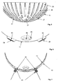
- FIG. 1 shows the main part of a dosing tank 14 without pressure tank and without closure.
- the lower part 10 of the container 14 consists of a solid plastic injection-molded part and has a rotationally symmetrical (eg spherical) inner contour. At the lower end there is an outlet 13 shown here only schematically , at the upper end a circumferential flange 12.
- the upper part of the container 14 consists of a thin film 11, preferably with a wall thickness between 50 microns and 500 microns, which is shaped substantially mirror-inverted to the inner contour of the lower part 10 .
- the film 11 consists of an impermeable to the filler material, such as a plastic film of PE or PET or a plastic composite film with an aluminum lining.
- the shaping of the film 11 can be done for example by a deep-drawing process.
- FIG. 2 shows the container 14 before filling with a liquid.
- the flexible film 11 is folded inwards and lies close to the inner contour of the lower part 10 .
- a residual volume of air in the outlet 13 is sucked off by applying a vacuum. Subsequently, the liquid is pressed into the container 14 under vacuum.
- FIG. 3 shows the container 14 with an integrally formed on the flange 12 or closely associated with him cylindrical housing 18 which is closed at its upper end by a double-walled lid 19 .
- the housing 18 and the cover 19 serve to protect the flexible film 11 against mechanical damage and light.
- the lid 19 consists of two interconnected by a plurality of spacers 20 wall plates 21 which have not aligned pressure equalization holes 22 .
- the bubble-free filling of the container 14 takes place in that the film 11 is pressed or sucked against the inner contour of the rigid lower part 10 .
- the remaining volume is exposed through the outlet 13 to a vacuum, and then the container 14 is filled from below.
- the container 14 is connected to or introduced into a pressure chamber (as described below with reference to FIG FIG. 10 explained), which surrounds at least the uppermost portion of the housing 18 tight.
- the air flowing through the holes 22 compressed air loads evenly on the film 11 and presses the liquid evenly through the outlet 13 from the container 14.
- the pressure chamber is appropriate designed so that it encloses the entire container 14 including housing 18 with the exception of the outlet 13 for emptying.
- the metered emptying of the container 14 via a uniform pressurization of the film 11 eg with compressed air.
- the penetration of air into the container 14 is excluded by the tight edge seal on the flange 12 .
- the film 11 itself will deform very uniformly during the entire emptying process and build up no intrinsic forces, since it neither rubs against a wall nor is it folded in an uncontrolled manner by a feed movement.
- the container 14 is also suitable for volumetric metering.
- the film 11 At the end of the emptying process, the film 11 will abut against the inner contour of the container lower part 10 in a form-fitting and wrinkle-free manner. Since the film 11 deforms absolutely force-free during the entire emptying process, the metered quantities applied over a fixed time unit will also remain constant at a constant compressed air pressure.
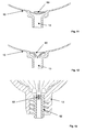
- FIG. 4 shows the lower part 10 of the container 14 with channel-shaped recesses 25, which extend radially to the outlet 13 of the container 14.
- the depressions 25 ensure a uniform over the time application rate of the liquid until the time of complete emptying.
- raised lands 26 are provided near the outlet 13 . The webs 26 keep the film 11 to the opening of the outlet 13 at a distance, thus ensuring the free flow of the liquid until complete emptying of the container 14th
- FIG. 5 Some of the webs 26 are interrupted in the vicinity of the outlet 13 (not shown here). In these areas 27 10 inductive or capacitive sensors 41 are mounted on the outside of the lower part, whose signals are located on a (not shown) evaluation circuit.
- the film 11 is provided at the areas 27 of the container base 10 with recesses 28 , in which, for example, circular metal foils 40 are introduced.
- FIG. 7 shows the lower part 10 in the deflated state in which the film 11 rests against the inner wall of the lower part 10 .
- the metal foils 40 are detected by the sensors 41 .
- the application of the film 11 is detected in the immediate vicinity of the container outlet 13 , so that one receives an indicator for the amount of adhesive residue.
- the position of the film 11 is queried at several (eg four) positions on the circumference.
- the evaluation circuit can operate so that it gives an advance warning to the container change when the film 11 applies at one of these positions. For example, if it is in three positions, the system can shut down the entire system to prevent incorrect metering.
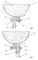
- a disc 30 is provided which closes the outlet 13 airtight with its flat surface.
- the liquid 33 of the container 14 is bubble-free on this surface.
- the greatest possible tightness during storage and transport is provided by a sealing lip 35 surrounding the outlet 13 (eg an O-ring).
- the rotationally symmetrical disc 30 is rotatably mounted about an offset relative to the outlet 13 axis.
- the disc 30 has a passage opening 31 into which a nipple 32 of a product tube can be inserted.
- the passage opening 31 tapers from outside to inside ( FIGS. 8 and 9 from bottom to top) in the form of a conical or dome shape such that the difference between the diameter of the through-hole 31 and that of the nipple 32 becomes at least zero or smaller from an initially positive value.
- This special shape of the through hole 31 prevents the formation of a Air cushion during insertion of the nipple 32.
- the product hose leads to the actual, downstream (not shown) metering valve.
- the nipple 32 is brought directly under the outlet 13 of the container 14 and pressed by a spring 34 a small piece into the opening 31 ( FIG. 9 ). If the product hose was completely filled with liquid, it is ensured that no air is introduced when connecting the product line. Since the outlet 13 is never open to the outside world, material can never flow out or air can be sucked in. The film effect described above can thus not affect. The connection and also the replacement of a dosing 14 take place bubble-free.
- dosing containers 14 can also be only partially emptied during a production day. However, these partially filled containers must be stored refrigerated or frozen overnight, over the weekend or until the next production order. Even when removing and reconnecting partially filled metering containers 14 prevents in FIGS. 8 and 9 The arrangement shown, the penetration of unwanted air bubbles in the product line and ensures a reliable, trouble-free production process.
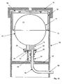
- FIG. 10 schematically illustrated emptying device comprises a pressure vessel 50 with a bayonet-type lockable lid 51, as it approximately EP 0 532 945 A1 is known.
- the nipple 32 is supported via the compression spring 34 on an intermediate wall 52 , which also carries an upwardly projecting locking pin 53 .
- a product hose 54 connected to the nipple 32 leads to an outer connecting piece 55.
- the pressure vessel 50 has an inner diameter such that it surrounds the inserted container 14 with little play.
- the container 14, with the in FIG. 3 shown housing 18 is pressed when shooting the lid 51 against the biased by the spring 34 nipple 32 down so that this centered in the conical or dome-shaped through hole 31 .
- the locking pin 53 engages in a blind hole 57 provided in the closure disk 30 of the container 14 .
- the lid 51 is rotated relative to the pressure vessel 50 , wherein it carries the container 14 , while the disc 30 is held by the locking pin 53 . In this way is opened simultaneously with the closing of the pressure vessel 50 of the container 14 and can now be emptied by introducing compressed into the vessel 50 through the product hose 54th
- the upwardly open nipple 32 prevents leakage of the liquid from the product tube 54, which would happen on loose or downwardly open product lines. Furthermore, this arrangement allows the waiver of a valve in the nipple 32, which would hinder the flow and would lead to a higher cleaning effort.
- a slit, soft, resilient closure membrane 60 is attached directly to the outlet 13 of the container 14 .
- FIG. 11 shows the lower part 10 with the membrane 60 in closed, FIG. 12 in open position.
- the diaphragm 60 provides sufficient resistance to inadvertent leakage of the fluid or aspiration of air during assembly.
- FIG. 13 In another, in FIG. 13 The alternative shown, instead of the membrane 60 in the outlet 13, an insert body 62 with fine through holes (capillaries) 63 (eg 0.1 to 1.0 mm in diameter) inserted, which prevent due to their flow resistance, an inadvertent leakage of the liquid.
- fine through holes (capillaries) 63 eg 0.1 to 1.0 mm in diameter
Landscapes
- Physics & Mathematics (AREA)
- Engineering & Computer Science (AREA)
- Power Engineering (AREA)
- Mechanical Engineering (AREA)
- Electromagnetism (AREA)
- Thermal Sciences (AREA)
- Fluid Mechanics (AREA)
- General Physics & Mathematics (AREA)
- Containers And Packaging Bodies Having A Special Means To Remove Contents (AREA)
- Basic Packing Technique (AREA)
- Closures For Containers (AREA)
Claims (11)
- Ensemble combiné formé
d'un récipient (14) pour substances susceptibles de s'écouler, comprenant une partie inférieure (10) rigide, concave, qui est pourvue d'une sortie (13), et une partie supérieure (11,) qui est constituée d'une feuille flexible formée selon une configuration convexe sensiblement symétrique au contour intérieur de la partie inférieure (10), la sortie (13) étant pourvue d'un système de fermeture (29) comprenant un disque (30), qui peut tourner autour d'un axe décalé par rapport à l'ouverture de la sortie (13) et présente une ouverture de passage (31) pour l'insertion d'un embout de prélèvement (32),
et d'un dispositif pour la vidange du récipient (14), qui comprend un réservoir (50) destiné à recevoir le récipient (14), un embout de prélèvement (32) pouvant être inséré dans l'ouverture de passage (31), et un système (51, 34) pour produire une pression d'application entre l'embout de prélèvement (32) et le récipient (14). - Ensemble combiné selon la revendication 1, dans lequel l'ouverture de passage (31), présentant de préférence une configuration conique ou en forme de calotte, se rétrécit de l'extérieur vers l'intérieur de manière telle, que la différence des diamètres de l'ouverture de passage (31) et de l'embout de prélèvement (32) décroit d'une valeur positive à au moins zéro.
- Ensemble combiné selon la revendication 1 ou la revendication 2, comprenant un carter (18) qui entoure la partie supérieure (11) et est relié à la partie inférieure (10), et qui, de préférence, est fermé par un couvercle (19) à double paroi, dont les deux disques de paroi (21) présentent des trous de compensation de pression (22) non mutuellement alignés.
- Ensemble combiné selon l'une des revendications précédentes, dans lequel la partie inférieure (10) et la partie supérieure (11) sont d'une configuration sensiblement demi-sphérique, et la partie supérieure (11) est fixée, de manière étanche à l'air, sur une bride (12) de la partie inférieure (10), qui s'étend dans le plan équatorial de la partie inférieure et est dirigée vers l'extérieur.
- Ensemble combiné selon l'une des revendications précédentes, dans lequel la partie inférieure (10) présente, à l'intérieur, des creux (25) en forme de goulotte, qui s'étendent sous forme de rayons en direction de la sortie (13) et présentent de préférence une profondeur croissante en direction de la sortie (13).
- Ensemble combiné selon l'une des revendications précédentes, dans lequel la partie inférieure (10) présente au moins une protubérance (26) agencée à proximité de la sortie (13) et faisant saillie vers l'intérieur.
- Ensemble combiné selon l'une des revendications précédentes, dans lequel sur la partie inférieure (10) est agencé un détecteur (41), qui relève l'application de la feuille (11) contre la paroi intérieure de la partie inférieure (10), et peut de préférence être couplé par voie inductive ou capacitive avec un corps métallique (40) placé sur la feuille (11).
- Ensemble combiné selon l'une des revendications précédentes, dans lequel plusieurs détecteurs (41) sont positionnés à proximité de la sortie (13).
- Ensemble combiné selon l'une des revendications précédentes, dans lequel le réservoir (50) destiné à recevoir le récipient (14), est configuré avec l'ouverture de passage (31) dirigée vers le bas, et l'embout de prélèvement (32) peut être inséré par le bas dans l'ouverture de passage (31).
- Ensemble combiné selon l'une des revendications précédentes, dans lequel le réservoir est un réservoir de pression (50) avec un couvercle (51), qui presse le récipient (14) contre l'embout de prélèvement (32) monté de manière élastique par ressort.
- Ensemble combiné selon l'une des revendications précédentes, dans lequel le réservoir de pression (50) présente une broche d'arrêt (53) destinée à s'engager dans une ouverture de maintien (57) existant dans le disque de fermeture (30).
Priority Applications (1)
| Application Number | Priority Date | Filing Date | Title |
|---|---|---|---|
| EP09013914A EP2161216B1 (fr) | 2008-03-18 | 2009-03-13 | Récipient pour substances pouvant s'écouler et procédé de dosage sans bulle de telles substances |
Applications Claiming Priority (2)
| Application Number | Priority Date | Filing Date | Title |
|---|---|---|---|
| DE200810014773 DE102008014773A1 (de) | 2008-03-18 | 2008-03-18 | Behälter für fließfähige Substanzen |
| PCT/EP2009/053010 WO2009115467A1 (fr) | 2008-03-18 | 2009-03-13 | Récipient pour substances fluides et dispositif de vidange |
Related Child Applications (1)
| Application Number | Title | Priority Date | Filing Date |
|---|---|---|---|
| EP09013914.8 Division-Into | 2009-11-05 |
Publications (2)
| Publication Number | Publication Date |
|---|---|
| EP2252527A1 EP2252527A1 (fr) | 2010-11-24 |
| EP2252527B1 true EP2252527B1 (fr) | 2013-02-27 |
Family
ID=40589658
Family Applications (2)
| Application Number | Title | Priority Date | Filing Date |
|---|---|---|---|
| EP09723450A Not-in-force EP2252527B1 (fr) | 2008-03-18 | 2009-03-13 | Récipient pour substances fluides et dispositif de vidange |
| EP09013914A Active EP2161216B1 (fr) | 2008-03-18 | 2009-03-13 | Récipient pour substances pouvant s'écouler et procédé de dosage sans bulle de telles substances |
Family Applications After (1)
| Application Number | Title | Priority Date | Filing Date |
|---|---|---|---|
| EP09013914A Active EP2161216B1 (fr) | 2008-03-18 | 2009-03-13 | Récipient pour substances pouvant s'écouler et procédé de dosage sans bulle de telles substances |
Country Status (7)
| Country | Link |
|---|---|
| US (1) | US8955720B2 (fr) |
| EP (2) | EP2252527B1 (fr) |
| JP (1) | JP5369169B2 (fr) |
| KR (1) | KR20100137518A (fr) |
| CN (1) | CN102066209B (fr) |
| DE (1) | DE102008014773A1 (fr) |
| WO (1) | WO2009115467A1 (fr) |
Families Citing this family (13)
| Publication number | Priority date | Publication date | Assignee | Title |
|---|---|---|---|---|
| EP2376346B3 (fr) * | 2009-07-09 | 2016-01-13 | Advanced Technology Materials, Inc. | Système de stockage à poche rigide et méthode de distribution d'un fluide |
| JP6004672B2 (ja) * | 2012-03-06 | 2016-10-12 | 日本キム株式会社 | 収容体 |
| BR112015019934A2 (pt) * | 2013-02-20 | 2017-07-18 | Dow Global Technologies Llc | bolsa para distribuir um líquido e sistema para distribuir um líquido |
| NL2010697C2 (en) * | 2013-04-24 | 2014-10-27 | Ihc Holland Ie Bv | Pressure compensation device. |
| KR20150046644A (ko) * | 2013-10-22 | 2015-04-30 | 삼성전자주식회사 | 나노 임프린트용 레진 디스펜서 |
| CN105979981A (zh) * | 2014-02-12 | 2016-09-28 | 赛诺菲-安万特德国有限公司 | 用于液体药剂的可压缩存储器 |
| WO2015121276A1 (fr) * | 2014-02-12 | 2015-08-20 | Sanofi-Aventis Deutschland Gmbh | Réservoir pour médicament liquide |
| JP6373734B2 (ja) * | 2014-11-21 | 2018-08-15 | サーパス工業株式会社 | バルブ一体型容器、それを備えた液体取出装置、およびバルブ一体型容器の製造方法 |
| US11001492B2 (en) * | 2017-04-11 | 2021-05-11 | Udo Tartler | Device for sealing and evacuating a container containing a paste-like liquid |
| US10604394B1 (en) * | 2019-02-07 | 2020-03-31 | Willo 32 Sas | Cartridge and a base unit for use in an oral care appliance |
| EP4056252A1 (fr) * | 2021-03-11 | 2022-09-14 | Brita GmbH | Cartouche de filtre destinée à être utilisée avec un dispositif de filtrage de liquide |
| DE102021125886A1 (de) | 2021-10-06 | 2023-04-06 | Shape Engineering GmbH | Verfahren, Behälter und Anordnung zum Ausbringen einer fließfähigen Substanz |
| WO2023057566A1 (fr) | 2021-10-06 | 2023-04-13 | Shape Engineering GmbH | Procédé, récipient et agencement pour distribuer une substance fluide |
Family Cites Families (40)
| Publication number | Priority date | Publication date | Assignee | Title |
|---|---|---|---|---|
| US3158296A (en) * | 1962-03-08 | 1964-11-24 | Cornelius Co | Fluid storage and discharge apparatus |
| US3945539A (en) * | 1966-08-16 | 1976-03-23 | Thiokol Corporation | Method and apparatus for expelling fluids |
| US3940031A (en) * | 1966-12-16 | 1976-02-24 | Thiokol Corporation | Reverse acting rolling diaphragm for expelling liquids |
| US3656662A (en) * | 1970-05-27 | 1972-04-18 | Us Air Force | Expulsion tank collector plate |
| US3849771A (en) * | 1973-01-24 | 1974-11-19 | R Applin | Liquid level alarm |
| US3862708A (en) * | 1973-10-11 | 1975-01-28 | Horix Mfg Co | Container filling device with flow control |
| SE7502318L (sv) * | 1975-03-03 | 1976-09-06 | Af Ekenstam Thuresson Bo | Emballage for flytande till halvfasta material, passande for smerre kvantiteter |
| GB1576126A (en) * | 1975-12-30 | 1980-10-01 | Metal Box Co Ltd | Closures |
| GB1583157A (en) * | 1976-05-07 | 1981-01-21 | Kenova Ab | Syringes |
| GB1576693A (en) * | 1977-12-01 | 1980-10-15 | Bosch Gmbh Robert | Pressure accumulator |
| JPS5628301A (en) * | 1979-08-15 | 1981-03-19 | Kazuo Sugimura | Accumulator improved in feeding and discharging of liquid |
| JPS59115796U (ja) * | 1983-01-27 | 1984-08-04 | 三菱電機株式会社 | 流体貯蔵タンク |
| US5017909A (en) * | 1989-01-06 | 1991-05-21 | Standex International Corporation | Capacitive liquid level sensor |
| US5135485A (en) * | 1991-02-25 | 1992-08-04 | Louis Cohen | Capacitance-type fluid level sensor for i.v. and catheter bags |
| DE9103038U1 (fr) | 1991-03-13 | 1992-07-16 | Thera Patent Gmbh & Co Kg Gesellschaft Fuer Industrielle Schutzrechte, 8031 Seefeld, De | |
| DE9111793U1 (fr) | 1991-09-20 | 1993-01-28 | Thera Patent Gmbh & Co Kg Gesellschaft Fuer Industrielle Schutzrechte, 8031 Seefeld, De | |
| DE9200521U1 (fr) | 1991-11-12 | 1993-03-25 | Thera Patent Gmbh & Co Kg Gesellschaft Fuer Industrielle Schutzrechte, 8031 Seefeld, De | |
| US5203470A (en) * | 1992-05-05 | 1993-04-20 | The Procter & Gamble Company | Separable bag-in-box composite container |
| GB9213300D0 (en) * | 1992-06-23 | 1992-08-05 | Tnt Materials Handling Ltd | Container |
| DE4335970A1 (de) | 1993-10-21 | 1995-04-27 | Hilti Ag | Folienbeutelpackung mit Folienbeutel und Bodenteil |
| JP3231525B2 (ja) | 1993-12-21 | 2001-11-26 | 株式会社細川洋行 | 吐出ガン用カートリッジ組立体 |
| JPH0891060A (ja) * | 1994-09-28 | 1996-04-09 | Sumitomo Electric Ind Ltd | 燃料タンク |
| DE19513223A1 (de) * | 1995-04-12 | 1996-10-17 | Matthias Hoffmeier | Behälter für viskoses Füllgut |
| DK0787655T3 (da) | 1996-02-05 | 2003-06-23 | 3M Espe Ag | Indretning til tømning af en rørfoliepose |
| IE960204A1 (en) | 1996-03-04 | 1997-09-10 | Loctite Ireland Ltd | Fluid flow connector and fluid pressure mechanism for fluids¹such as adhesives |
| DE19810217A1 (de) * | 1998-03-10 | 1999-09-16 | Oliver Weis | Flüssigkeitsspender, insbesondere Flüssigarzneispender, Kosmetikapplikator, Tintenschreibgerät oder dergleichen |
| US7127943B1 (en) * | 1999-01-19 | 2006-10-31 | Rocky Mountain Research, Inc. | Method and apparatus for detection of fluid level in a container |
| RU2158699C1 (ru) * | 1999-02-23 | 2000-11-10 | Открытое акционерное общество НПО Энергомаш имени академика В.П. Глушко | Бак для хранения и вытеснения жидкости |
| DE19949985C2 (de) * | 1999-10-15 | 2001-08-16 | Sie Sensorik Ind Elektronik Gm | Kapazitiver Sensor zur Detektion des Füllstandes eines Mediums in einem Behälter |
| JP2001167793A (ja) * | 1999-12-10 | 2001-06-22 | Yuasa Corp | 固体状電池およびその製造方法 |
| JP4259728B2 (ja) * | 2000-06-05 | 2009-04-30 | 横浜ゴム株式会社 | 飛翔体の燃料タンクに用いられる可撓性袋状タンクの固定方法。 |
| JP3636052B2 (ja) | 2000-09-25 | 2005-04-06 | サンスター技研株式会社 | 軟質容器の製造方法及び高粘調液充填体 |
| US20040094572A1 (en) * | 2002-11-15 | 2004-05-20 | Eureka Technologies Innovation Engineering (1987) Ltd. | Container for pressurized liquids |
| DE10311080B4 (de) | 2003-03-13 | 2006-01-12 | Delo Industrieklebstoffe Gmbh & Co. Kg | Kartusche für fließfähige Massen |
| US7059487B2 (en) * | 2003-04-29 | 2006-06-13 | Tetra Laval Holdings & Finance, Sa | Collapsible semi-rigid container |
| US7377162B2 (en) * | 2005-06-28 | 2008-05-27 | Keurig, Incorporated | Method and apparatus for liquid level sensing |
| JP4991724B2 (ja) * | 2005-08-26 | 2012-08-01 | ネクスト−アールオー・インコーポレーテッド | 逆浸透濾過システム保管タンク |
| US20080105708A1 (en) * | 2006-11-06 | 2008-05-08 | Nix, Inc. | Fluid supply container and fuel cell system using the same |
| US7802471B2 (en) * | 2007-12-28 | 2010-09-28 | Sieh Philip J | Liquid level sensing device and method |
| US8079126B2 (en) * | 2008-01-25 | 2011-12-20 | Pratt & Whitney Rocketdyne, Inc. | Friction stir welded bladder fuel tank |
-
2008
- 2008-03-18 DE DE200810014773 patent/DE102008014773A1/de not_active Ceased
-
2009
- 2009-03-13 EP EP09723450A patent/EP2252527B1/fr not_active Not-in-force
- 2009-03-13 WO PCT/EP2009/053010 patent/WO2009115467A1/fr active Application Filing
- 2009-03-13 CN CN200980109800.4A patent/CN102066209B/zh active Active
- 2009-03-13 JP JP2011500165A patent/JP5369169B2/ja active Active
- 2009-03-13 EP EP09013914A patent/EP2161216B1/fr active Active
- 2009-03-13 KR KR1020107023206A patent/KR20100137518A/ko active IP Right Grant
- 2009-03-13 US US12/864,802 patent/US8955720B2/en active Active
Also Published As
| Publication number | Publication date |
|---|---|
| WO2009115467A1 (fr) | 2009-09-24 |
| KR20100137518A (ko) | 2010-12-30 |
| EP2252527A1 (fr) | 2010-11-24 |
| CN102066209B (zh) | 2014-11-12 |
| JP5369169B2 (ja) | 2013-12-18 |
| US20100308075A1 (en) | 2010-12-09 |
| EP2161216B1 (fr) | 2012-05-23 |
| DE102008014773A1 (de) | 2009-10-08 |
| JP2011515282A (ja) | 2011-05-19 |
| US8955720B2 (en) | 2015-02-17 |
| EP2161216A1 (fr) | 2010-03-10 |
| CN102066209A (zh) | 2011-05-18 |
Similar Documents
| Publication | Publication Date | Title |
|---|---|---|
| EP2252527B1 (fr) | Récipient pour substances fluides et dispositif de vidange | |
| DE2544671C3 (de) | Behälter zur dosierten Abgabe von Flüssigkeiten | |
| EP1338528B1 (fr) | Utilisation d'un récipient pour liquide médical | |
| EP2931428B1 (fr) | Sachet en film pour le stockage en réserve d'un fluide et dispositif de fourniture d'un fluide et procédé de fabrication d'un sachet en film | |
| EP0697348B1 (fr) | Ensemble vanne de distribution et poche soudée avec celui-ci | |
| DE3740823A1 (de) | Vorrichtung zur entnahme von fluessigkeiten aus einem behaelter und anordnung zur herstellung derselben | |
| DE2709730A1 (de) | Tintenversorgungseinrichtung in einem tintenschreib- und registrierwerk | |
| EP1473246A1 (fr) | Ensemble comportant une vanne de distribution et une poche liée étanchement avec celle-ci | |
| EP3820788A1 (fr) | Récipient sous pression en matière plastique | |
| EP3368437B1 (fr) | Tube en matiere plastique | |
| DE4403755A1 (de) | Austragvorrichtung für Medien | |
| DE102014014317B4 (de) | Vorrichtung und Verfahren zum messmittellosen Befüllen eines Behältnisses | |
| WO2010124907A1 (fr) | Procédé de contrôle de l'étanchéité d'un réservoir rempli d'un fluide | |
| DE102014012171B4 (de) | Vorrichtung zum Auspressen von viskosen Massen aus Behältern | |
| DE10311080B4 (de) | Kartusche für fließfähige Massen | |
| DE102006054606A1 (de) | Vorrichtung und Verfahren zum dosierten Abfüllen von Medien | |
| DE202017002628U1 (de) | In seiner Form veränderbares flexibles Behältnis | |
| US20100206898A1 (en) | Method and device for the metered dispensing of a medium | |
| DE2920747C3 (de) | Vorrichtung zum abdichtenden Verbinden eines Transportbehälters mit der gestellfesten, nach oben offenen Aufnahme einer Einrichtung zur dosierten Abgabe von Flüssigkeiten in Geräten zum Ausgeben von Getränken | |
| EP2756854B1 (fr) | Poche de fluide médicale | |
| DE2324080C2 (de) | Dosiervorrichtung | |
| DE10326474B4 (de) | Druckbehälter | |
| DE19810217A1 (de) | Flüssigkeitsspender, insbesondere Flüssigarzneispender, Kosmetikapplikator, Tintenschreibgerät oder dergleichen | |
| DE4003146C2 (de) | Beutel | |
| DE69920525T2 (de) | Flüssigkeitsabgabesystem |
Legal Events
| Date | Code | Title | Description |
|---|---|---|---|
| PUAI | Public reference made under article 153(3) epc to a published international application that has entered the european phase |
Free format text: ORIGINAL CODE: 0009012 |
|
| 17P | Request for examination filed |
Effective date: 20091110 |
|
| AK | Designated contracting states |
Kind code of ref document: A1 Designated state(s): AT BE BG CH CY CZ DE DK EE ES FI FR GB GR HR HU IE IS IT LI LT LU LV MC MK MT NL NO PL PT RO SE SI SK TR |
|
| AX | Request for extension of the european patent |
Extension state: AL BA RS |
|
| 17Q | First examination report despatched |
Effective date: 20110401 |
|
| DAX | Request for extension of the european patent (deleted) | ||
| REG | Reference to a national code |
Ref country code: DE Ref legal event code: R079 Ref document number: 502009006365 Country of ref document: DE Free format text: PREVIOUS MAIN CLASS: B65D0075320000 Ipc: G01F0023260000 |
|
| RIC1 | Information provided on ipc code assigned before grant |
Ipc: B65D 75/32 20060101ALI20110811BHEP Ipc: G01F 23/26 20060101AFI20110811BHEP Ipc: B05C 17/015 20060101ALI20110811BHEP Ipc: B65D 47/26 20060101ALI20110811BHEP Ipc: B67D 7/02 20100101ALI20110811BHEP Ipc: B65D 83/00 20060101ALI20110811BHEP Ipc: A61M 5/162 20060101ALI20110811BHEP |
|
| GRAP | Despatch of communication of intention to grant a patent |
Free format text: ORIGINAL CODE: EPIDOSNIGR1 |
|
| GRAJ | Information related to disapproval of communication of intention to grant by the applicant or resumption of examination proceedings by the epo deleted |
Free format text: ORIGINAL CODE: EPIDOSDIGR1 |
|
| GRAP | Despatch of communication of intention to grant a patent |
Free format text: ORIGINAL CODE: EPIDOSNIGR1 |
|
| GRAS | Grant fee paid |
Free format text: ORIGINAL CODE: EPIDOSNIGR3 |
|
| GRAA | (expected) grant |
Free format text: ORIGINAL CODE: 0009210 |
|
| AK | Designated contracting states |
Kind code of ref document: B1 Designated state(s): AT BE BG CH CY CZ DE DK EE ES FI FR GB GR HR HU IE IS IT LI LT LU LV MC MK MT NL NO PL PT RO SE SI SK TR |
|
| REG | Reference to a national code |
Ref country code: GB Ref legal event code: FG4D Free format text: NOT ENGLISH |
|
| REG | Reference to a national code |
Ref country code: CH Ref legal event code: EP |
|
| REG | Reference to a national code |
Ref country code: AT Ref legal event code: REF Ref document number: 598738 Country of ref document: AT Kind code of ref document: T Effective date: 20130315 |
|
| REG | Reference to a national code |
Ref country code: IE Ref legal event code: FG4D Free format text: LANGUAGE OF EP DOCUMENT: GERMAN |
|
| REG | Reference to a national code |
Ref country code: DE Ref legal event code: R096 Ref document number: 502009006365 Country of ref document: DE Effective date: 20130425 |
|
| REG | Reference to a national code |
Ref country code: LT Ref legal event code: MG4D |
|
| PG25 | Lapsed in a contracting state [announced via postgrant information from national office to epo] |
Ref country code: IS Free format text: LAPSE BECAUSE OF FAILURE TO SUBMIT A TRANSLATION OF THE DESCRIPTION OR TO PAY THE FEE WITHIN THE PRESCRIBED TIME-LIMIT Effective date: 20130627 Ref country code: BG Free format text: LAPSE BECAUSE OF FAILURE TO SUBMIT A TRANSLATION OF THE DESCRIPTION OR TO PAY THE FEE WITHIN THE PRESCRIBED TIME-LIMIT Effective date: 20130527 Ref country code: SE Free format text: LAPSE BECAUSE OF FAILURE TO SUBMIT A TRANSLATION OF THE DESCRIPTION OR TO PAY THE FEE WITHIN THE PRESCRIBED TIME-LIMIT Effective date: 20130227 Ref country code: LT Free format text: LAPSE BECAUSE OF FAILURE TO SUBMIT A TRANSLATION OF THE DESCRIPTION OR TO PAY THE FEE WITHIN THE PRESCRIBED TIME-LIMIT Effective date: 20130227 Ref country code: NO Free format text: LAPSE BECAUSE OF FAILURE TO SUBMIT A TRANSLATION OF THE DESCRIPTION OR TO PAY THE FEE WITHIN THE PRESCRIBED TIME-LIMIT Effective date: 20130527 Ref country code: ES Free format text: LAPSE BECAUSE OF FAILURE TO SUBMIT A TRANSLATION OF THE DESCRIPTION OR TO PAY THE FEE WITHIN THE PRESCRIBED TIME-LIMIT Effective date: 20130607 |
|
| REG | Reference to a national code |
Ref country code: NL Ref legal event code: VDEP Effective date: 20130227 |
|
| PG25 | Lapsed in a contracting state [announced via postgrant information from national office to epo] |
Ref country code: PT Free format text: LAPSE BECAUSE OF FAILURE TO SUBMIT A TRANSLATION OF THE DESCRIPTION OR TO PAY THE FEE WITHIN THE PRESCRIBED TIME-LIMIT Effective date: 20130627 Ref country code: SI Free format text: LAPSE BECAUSE OF FAILURE TO SUBMIT A TRANSLATION OF THE DESCRIPTION OR TO PAY THE FEE WITHIN THE PRESCRIBED TIME-LIMIT Effective date: 20130227 Ref country code: PL Free format text: LAPSE BECAUSE OF FAILURE TO SUBMIT A TRANSLATION OF THE DESCRIPTION OR TO PAY THE FEE WITHIN THE PRESCRIBED TIME-LIMIT Effective date: 20130227 Ref country code: GR Free format text: LAPSE BECAUSE OF FAILURE TO SUBMIT A TRANSLATION OF THE DESCRIPTION OR TO PAY THE FEE WITHIN THE PRESCRIBED TIME-LIMIT Effective date: 20130528 Ref country code: FI Free format text: LAPSE BECAUSE OF FAILURE TO SUBMIT A TRANSLATION OF THE DESCRIPTION OR TO PAY THE FEE WITHIN THE PRESCRIBED TIME-LIMIT Effective date: 20130227 Ref country code: LV Free format text: LAPSE BECAUSE OF FAILURE TO SUBMIT A TRANSLATION OF THE DESCRIPTION OR TO PAY THE FEE WITHIN THE PRESCRIBED TIME-LIMIT Effective date: 20130227 |
|
| BERE | Be: lapsed |
Owner name: DELO INDUSTRIEKLEBSTOFFE G.M.B.H. & CO. KGAA Effective date: 20130331 |
|
| PG25 | Lapsed in a contracting state [announced via postgrant information from national office to epo] |
Ref country code: HR Free format text: LAPSE BECAUSE OF FAILURE TO SUBMIT A TRANSLATION OF THE DESCRIPTION OR TO PAY THE FEE WITHIN THE PRESCRIBED TIME-LIMIT Effective date: 20130227 |
|
| PG25 | Lapsed in a contracting state [announced via postgrant information from national office to epo] |
Ref country code: RO Free format text: LAPSE BECAUSE OF FAILURE TO SUBMIT A TRANSLATION OF THE DESCRIPTION OR TO PAY THE FEE WITHIN THE PRESCRIBED TIME-LIMIT Effective date: 20130227 Ref country code: MC Free format text: LAPSE BECAUSE OF NON-PAYMENT OF DUE FEES Effective date: 20130331 Ref country code: NL Free format text: LAPSE BECAUSE OF FAILURE TO SUBMIT A TRANSLATION OF THE DESCRIPTION OR TO PAY THE FEE WITHIN THE PRESCRIBED TIME-LIMIT Effective date: 20130227 Ref country code: SK Free format text: LAPSE BECAUSE OF FAILURE TO SUBMIT A TRANSLATION OF THE DESCRIPTION OR TO PAY THE FEE WITHIN THE PRESCRIBED TIME-LIMIT Effective date: 20130227 Ref country code: DK Free format text: LAPSE BECAUSE OF FAILURE TO SUBMIT A TRANSLATION OF THE DESCRIPTION OR TO PAY THE FEE WITHIN THE PRESCRIBED TIME-LIMIT Effective date: 20130227 Ref country code: EE Free format text: LAPSE BECAUSE OF FAILURE TO SUBMIT A TRANSLATION OF THE DESCRIPTION OR TO PAY THE FEE WITHIN THE PRESCRIBED TIME-LIMIT Effective date: 20130227 Ref country code: CZ Free format text: LAPSE BECAUSE OF FAILURE TO SUBMIT A TRANSLATION OF THE DESCRIPTION OR TO PAY THE FEE WITHIN THE PRESCRIBED TIME-LIMIT Effective date: 20130227 |
|
| REG | Reference to a national code |
Ref country code: CH Ref legal event code: PL |
|
| PG25 | Lapsed in a contracting state [announced via postgrant information from national office to epo] |
Ref country code: CY Free format text: LAPSE BECAUSE OF FAILURE TO SUBMIT A TRANSLATION OF THE DESCRIPTION OR TO PAY THE FEE WITHIN THE PRESCRIBED TIME-LIMIT Effective date: 20130227 |
|
| PG25 | Lapsed in a contracting state [announced via postgrant information from national office to epo] |
Ref country code: IT Free format text: LAPSE BECAUSE OF FAILURE TO SUBMIT A TRANSLATION OF THE DESCRIPTION OR TO PAY THE FEE WITHIN THE PRESCRIBED TIME-LIMIT Effective date: 20130227 |
|
| REG | Reference to a national code |
Ref country code: IE Ref legal event code: MM4A |
|
| PLBE | No opposition filed within time limit |
Free format text: ORIGINAL CODE: 0009261 |
|
| STAA | Information on the status of an ep patent application or granted ep patent |
Free format text: STATUS: NO OPPOSITION FILED WITHIN TIME LIMIT |
|
| GBPC | Gb: european patent ceased through non-payment of renewal fee |
Effective date: 20130527 |
|
| PG25 | Lapsed in a contracting state [announced via postgrant information from national office to epo] |
Ref country code: LI Free format text: LAPSE BECAUSE OF NON-PAYMENT OF DUE FEES Effective date: 20130331 Ref country code: CH Free format text: LAPSE BECAUSE OF NON-PAYMENT OF DUE FEES Effective date: 20130331 Ref country code: IE Free format text: LAPSE BECAUSE OF NON-PAYMENT OF DUE FEES Effective date: 20130313 Ref country code: BE Free format text: LAPSE BECAUSE OF NON-PAYMENT OF DUE FEES Effective date: 20130331 |
|
| 26N | No opposition filed |
Effective date: 20131128 |
|
| REG | Reference to a national code |
Ref country code: DE Ref legal event code: R097 Ref document number: 502009006365 Country of ref document: DE Effective date: 20131128 |
|
| PG25 | Lapsed in a contracting state [announced via postgrant information from national office to epo] |
Ref country code: GB Free format text: LAPSE BECAUSE OF NON-PAYMENT OF DUE FEES Effective date: 20130527 |
|
| PG25 | Lapsed in a contracting state [announced via postgrant information from national office to epo] |
Ref country code: MT Free format text: LAPSE BECAUSE OF FAILURE TO SUBMIT A TRANSLATION OF THE DESCRIPTION OR TO PAY THE FEE WITHIN THE PRESCRIBED TIME-LIMIT Effective date: 20130227 |
|
| PGFP | Annual fee paid to national office [announced via postgrant information from national office to epo] |
Ref country code: DE Payment date: 20140520 Year of fee payment: 6 |
|
| REG | Reference to a national code |
Ref country code: AT Ref legal event code: MM01 Ref document number: 598738 Country of ref document: AT Kind code of ref document: T Effective date: 20140313 |
|
| PG25 | Lapsed in a contracting state [announced via postgrant information from national office to epo] |
Ref country code: TR Free format text: LAPSE BECAUSE OF FAILURE TO SUBMIT A TRANSLATION OF THE DESCRIPTION OR TO PAY THE FEE WITHIN THE PRESCRIBED TIME-LIMIT Effective date: 20130227 |
|
| PG25 | Lapsed in a contracting state [announced via postgrant information from national office to epo] |
Ref country code: LU Free format text: LAPSE BECAUSE OF NON-PAYMENT OF DUE FEES Effective date: 20130313 Ref country code: MK Free format text: LAPSE BECAUSE OF FAILURE TO SUBMIT A TRANSLATION OF THE DESCRIPTION OR TO PAY THE FEE WITHIN THE PRESCRIBED TIME-LIMIT Effective date: 20130227 Ref country code: HU Free format text: LAPSE BECAUSE OF FAILURE TO SUBMIT A TRANSLATION OF THE DESCRIPTION OR TO PAY THE FEE WITHIN THE PRESCRIBED TIME-LIMIT; INVALID AB INITIO Effective date: 20090313 |
|
| PG25 | Lapsed in a contracting state [announced via postgrant information from national office to epo] |
Ref country code: AT Free format text: LAPSE BECAUSE OF NON-PAYMENT OF DUE FEES Effective date: 20140313 |
|
| REG | Reference to a national code |
Ref country code: DE Ref legal event code: R119 Ref document number: 502009006365 Country of ref document: DE |
|
| PG25 | Lapsed in a contracting state [announced via postgrant information from national office to epo] |
Ref country code: DE Free format text: LAPSE BECAUSE OF NON-PAYMENT OF DUE FEES Effective date: 20151001 |
|
| PG25 | Lapsed in a contracting state [announced via postgrant information from national office to epo] |
Ref country code: FR Free format text: LAPSE BECAUSE OF NON-PAYMENT OF DUE FEES Effective date: 20130331 |