EP2249017A1 - Abwärme nutzende vorrichtung für einen verbrennungsmotor - Google Patents
Abwärme nutzende vorrichtung für einen verbrennungsmotor Download PDFInfo
- Publication number
- EP2249017A1 EP2249017A1 EP09711518A EP09711518A EP2249017A1 EP 2249017 A1 EP2249017 A1 EP 2249017A1 EP 09711518 A EP09711518 A EP 09711518A EP 09711518 A EP09711518 A EP 09711518A EP 2249017 A1 EP2249017 A1 EP 2249017A1
- Authority
- EP
- European Patent Office
- Prior art keywords
- evaporator
- working fluid
- flow rate
- waste heat
- internal combustion
- Prior art date
- Legal status (The legal status is an assumption and is not a legal conclusion. Google has not performed a legal analysis and makes no representation as to the accuracy of the status listed.)
- Granted
Links
Images


Classifications
-
- F—MECHANICAL ENGINEERING; LIGHTING; HEATING; WEAPONS; BLASTING
- F02—COMBUSTION ENGINES; HOT-GAS OR COMBUSTION-PRODUCT ENGINE PLANTS
- F02G—HOT GAS OR COMBUSTION-PRODUCT POSITIVE-DISPLACEMENT ENGINE PLANTS; USE OF WASTE HEAT OF COMBUSTION ENGINES; NOT OTHERWISE PROVIDED FOR
- F02G5/00—Profiting from waste heat of combustion engines, not otherwise provided for
- F02G5/02—Profiting from waste heat of exhaust gases
- F02G5/04—Profiting from waste heat of exhaust gases in combination with other waste heat from combustion engines
-
- F—MECHANICAL ENGINEERING; LIGHTING; HEATING; WEAPONS; BLASTING
- F01—MACHINES OR ENGINES IN GENERAL; ENGINE PLANTS IN GENERAL; STEAM ENGINES
- F01K—STEAM ENGINE PLANTS; STEAM ACCUMULATORS; ENGINE PLANTS NOT OTHERWISE PROVIDED FOR; ENGINES USING SPECIAL WORKING FLUIDS OR CYCLES
- F01K23/00—Plants characterised by more than one engine delivering power external to the plant, the engines being driven by different fluids
- F01K23/02—Plants characterised by more than one engine delivering power external to the plant, the engines being driven by different fluids the engine cycles being thermally coupled
- F01K23/06—Plants characterised by more than one engine delivering power external to the plant, the engines being driven by different fluids the engine cycles being thermally coupled combustion heat from one cycle heating the fluid in another cycle
- F01K23/065—Plants characterised by more than one engine delivering power external to the plant, the engines being driven by different fluids the engine cycles being thermally coupled combustion heat from one cycle heating the fluid in another cycle the combustion taking place in an internal combustion piston engine, e.g. a diesel engine
-
- F—MECHANICAL ENGINEERING; LIGHTING; HEATING; WEAPONS; BLASTING
- F02—COMBUSTION ENGINES; HOT-GAS OR COMBUSTION-PRODUCT ENGINE PLANTS
- F02G—HOT GAS OR COMBUSTION-PRODUCT POSITIVE-DISPLACEMENT ENGINE PLANTS; USE OF WASTE HEAT OF COMBUSTION ENGINES; NOT OTHERWISE PROVIDED FOR
- F02G2260/00—Recuperating heat from exhaust gases of combustion engines and heat from cooling circuits
-
- Y—GENERAL TAGGING OF NEW TECHNOLOGICAL DEVELOPMENTS; GENERAL TAGGING OF CROSS-SECTIONAL TECHNOLOGIES SPANNING OVER SEVERAL SECTIONS OF THE IPC; TECHNICAL SUBJECTS COVERED BY FORMER USPC CROSS-REFERENCE ART COLLECTIONS [XRACs] AND DIGESTS
- Y02—TECHNOLOGIES OR APPLICATIONS FOR MITIGATION OR ADAPTATION AGAINST CLIMATE CHANGE
- Y02T—CLIMATE CHANGE MITIGATION TECHNOLOGIES RELATED TO TRANSPORTATION
- Y02T10/00—Road transport of goods or passengers
- Y02T10/10—Internal combustion engine [ICE] based vehicles
- Y02T10/12—Improving ICE efficiencies
Definitions
- the present invention relates to a waste heat utilization device for an internal combustion engine, and more specifically, to a waste heat utilization device for an internal combustion engine, which is suitable for a vehicle.
- This type of waste heat utilization device for an internal combustion engine includes, for example, a Rankine cycle that is applied to a vehicle equipped with an engine and recovers energy from waste heat generated in the engine, and an ECU (electrical control unit) that controls the Rankine cycle.
- the Rankine cycle makes a refrigeration circuit where refrigerant runs through a pump, an evaporator, an expander and a condenser in this order.
- One possible way to recover engine waste heat is to provide the Rankine cycle with not only an evaporator but also an exhaust gas heat exchanger for absorbing heat from engine exhaust gas.
- the invention has been made in light of the above issue. It is an object of the invention to provide a waste heat utilization device for an internal combustion engine, which is capable of effectively enhancing recovered energy in a Rankine cycle having an exhaust gas heat exchanger.
- the waste heat utilization device for an internal combustion engine of the invention has a Rankine cycle including an evaporator that heats a working fluid by using waste heat of an internal combustion engine, a heater that further heats the working fluid leaving the evaporator by using the waste heat of the internal combustion engine, an expander that expands the working fluid discharged from the heater and generates a driving force, a condenser that condenses the working fluid discharged from the expander, and a pump that delivers to the evaporator the working fluid discharged from the condenser; and control means that controls actuation of the Rankine cycle.
- the evaporator is capable of absorbing heat from the waste heat with an upper limit of preset maximum heat absorption amount and transferring the heat to the working fluid.
- the control means controls the flow rate of the working fluid so that the working fluid evaporated by the evaporator comes into a superheated state in the heater, when the working fluid enters the evaporator at a flow rate equal to or lower than preset flow rate at which the working fluid can absorb the preset maximum heat absorption amount of heat, and controls the flow rate of the working fluid so that the working fluid that overflows the evaporator is evaporated by the heater and then comes into the superheat state, when the working fluid enters the evaporator at a flow rate higher than the preset flow rate.
- the heater functions as a so-called superheater when the working fluid enters the evaporator at a flow rate equal to or lower than the preset flow rate at which the working fluid can absorb the preset maximum heat absorption amount of heat.
- a superheat level in the heater can be controlled by controlling the flow rate of the working fluid.
- the control means increases the rotation frequency of the pump during the flow rate control when the working fluid entering the expander has an expander inlet temperature equal to or higher than preset expander inlet temperature.
- the control means reduces the rotation frequency of the pump during the flow rate control when the expander inlet temperature of the working fluid entering the expander is lower than the preset expander inlet temperature, and the refrigerant's superheat level in the evaporator is equal to or lower than preset superheat level.
- the control means reduces the rotation frequency of the pump during the flow rate control when temperature difference between condensing temperature of the working fluid in the condenser and outside air temperature is equal to or higher than preset temperature difference.
- the condensing temperature can be decreased by reducing the flow rate of the working fluid. As a result, the recovered energy can be more effectively enhanced.
- the control means reduces the rotation frequency of the pump during the flow rate control when evaporator outlet temperature of coolant leaving the evaporator is equal to or lower than preset evaporator outlet temperature.
- the heat absorption amount of the evaporator can be set at a value corresponding to waste heat amount of the internal combustion engine even when the engine is under low load by reducing the flow rate of the working fluid entering the evaporator.
- the recovered energy can be therefore more effectively enhanced.
- the waste heat utilization device for an internal combustion engine has a coolant circuit including a radiator in which the coolant is refrigerated according to the coolant temperature after being heated with waste heat by refrigerating the internal combustion engine and passing through the evaporator.
- the control means increases the rotation frequency of the pump during the flow rate control when the working fluid flows into the radiator.
- the absorption amount in the evaporator can be increased as much as possible by increasing the flow rate of the working fluid entering the evaporator. As a result, the recovered energy can be more effectively enhanced.
- the waste heat utilization device for an internal combustion engine has a generator that converts driving force generated in the expander into electric power.
- the control means reduces rotation frequency of a fan that carries out heat exchange between the working fluid and outside air in the condenser when power generation amount in the generator is equal to or more than required power generation amount that is required by an external device disposed outside the waste heat utilization device, and increases the rotation frequency of the fan when the power generation amount is less than the required power generation amount.
- heat radiation amount in the condenser can be directly controlled, and therefore, the power generation amount can be adjusted to the required amount.
- the heater is an exhaust gas heat exchanger that causes exhaust gas of the internal combustion engine as exhaust heat to carry out heat exchange with the working fluid, and includes bypass means that circulates the exhaust gas so that the exhaust gas bypasses the exhaust gas heat exchanger.
- the control means circulates the exhaust gas by using the bypass means so that the exhaust gas bypasses the exhaust gas heat exchanger when the expander inlet temperature is equal to or higher than preset second expander inlet temperature, and delivers the exhaust gas to the exhaust gas heat exchanger by using the bypass means when the expander inlet temperature is lower than the preset second expander inlet temperature.
- FIG. 1 is a diagram schematically showing a configuration of a waste heat utilization device 2 of the present embodiment.
- the waste heat utilization device 2 includes, for example, a coolant circuit 6 that refrigerates a vehicle engine (internal combustion engine) 4, and a Rankine cycle circuit (Rankine cycle) 8 (hereinafter, referred to as an RC circuit) that recovers the waste heat of the engine 4.
- a coolant circuit 6 that refrigerates a vehicle engine (internal combustion engine) 4
- Rankine cycle circuit Rankine cycle circuit 8
- the coolant circuit 6 is provided, in a coolant channel 7 extending from the engine 4, with an evaporator 10, a radiator 12, a thermostat 14 and a water pump 16 in the order from the upstream side of a coolant flow.
- the coolant circuit 6 thus forms a closed circuit.
- the evaporator 10 exchanges heat between a coolant of the coolant circuit 6 and a refrigerant of the RC circuit 8.
- the evaporator 10 thus transfers the waste heat of the engine 4 to the RC circuit 8 side by using the coolant heated in the engine 4, or hot water, as a heat medium, thereby recovering the waste heat of the engine 4.
- the coolant whose heat is absorbed by the refrigerant when passing through the evaporator 10, again turns into hot water by refrigerating the engine 4.
- the radiator 12 is connected in series with the evaporator 10, and further refrigerates the coolant, whose heat has been absorbed by the refrigerant when the coolant passes through the evaporator 10, by carrying out heat exchange between the coolant and outside air.
- the thermostat 14 is a mechanical three-way change valve that controls amount of the coolant to be carried to the radiator 12 according to coolant temperature.
- the thermostat 14 has two inlet ports and one outlet port. Connected to the two inlet ports are a flow channel 7a extending from the radiator 12 and a bypass channel 7c that extends from a flow channel 7b interposed between the evaporator 10 and the radiator 12 to bypass the radiator 12.
- the amount of the coolant to be carried to the radiator 12 is adjusted according to the coolant temperature, to thereby prevent the engine 4 from being overheated.
- the water pump 16 is mounted on the engine 4. The water pump 16 is driven according to revolution of the engine 4 and thus makes the coolant properly circulate through the coolant circuit 6.
- a refrigerant channel 9 of the RC circuit 8 is provided with the evaporator 10, a heater 18, an expander 20, a condenser 22, a vapor-liquid separator 24, and a refrigerant pump 26 in the order from the upstream side of a refrigerant flow.
- the RC circuit 8 thus forms a closed circuit.
- the heater 18 is, for example, an exhaust gas heat exchanger that heats the refrigerant by using exhaust gas flowing through an exhaust gas pipe 28 of the engine 4, and heats the refrigerant in the evaporator 10.
- the expander 20 is a positive displacement fluid machine that expands the refrigerant, which has been heated into superheated vapor by the evaporator 10 and the heater 18, to generate a rotational driving force.
- the expander 20 is mechanically connected to a generator 30 that makes the rotational driving force utilizable outside the waste heat utilization device 2 by converting the generated rotational driving force into electric power.
- the condenser 22 is an air-cooled heat exchanger that exchanges heat between the refrigerant discharged from the expander 20 and outside air to change the refrigerant into a condensate liquid by a condenser fan 23 being rotated according to a signal entered into an actuator 23a.
- the gas-liquid separator 24 is a receiver that divides the refrigerant condensed in the condenser 22 into two layers of gas and liquid. Only the liquid refrigerant separated here is discharged to the refrigerant pump 26 side.
- the refrigerant pump 26 is an electric pump that is driven according to a signal entered into an actuator 26a thereof.
- the liquid refrigerant condensed in the condenser 22 and separated in the gas-liquid separator 24 is pumped to the evaporator 10 side by the refrigerant pump 26, thereby properly circulating through the RC circuit 8.
- the waste heat utilization device 2 is provided with an electrical control unit (ECU) (control means) 32 that carries out comprehensive control of a vehicle and the waste heat utilization device 2. Not only the actuators 23a and 26a but also various sensors are electrically connected to the ECU 32.
- ECU electrical control unit
- the coolant circuit 6 is provided with a waste heat temperature sensor 34, which detects engine waste heat temperature T 1 that is the temperature of the coolant heated in the engine 4, between an outlet of the engine 4 and an inlet of the evaporator 10; an evaporator outlet temperature sensor 36, which detects evaporator-outlet coolant temperature T 2 , between the outlet of the evaporator 10 and a diverging point at which the bypass channel 7c diverges from the flow channel 7b; and a radiator passing-water flow-rate sensor 38, which detects flow rate F of coolant passing through in the radiator 12, between the radiator 12 and the thermostat 14.
- a waste heat temperature sensor 34 which detects engine waste heat temperature T 1 that is the temperature of the coolant heated in the engine 4, between an outlet of the engine 4 and an inlet of the evaporator 10
- an evaporator outlet temperature sensor 36 which detects evaporator-outlet coolant temperature T 2 , between the outlet of the evaporator 10 and a diverging point at which the bypass channel 7c diverges
- the RC circuit 8 is provided with an expander inlet temperature sensor 40, which detects expander-inlet refrigerant temperature T 3 , between an outlet of the exhaust gas heat exchanger 18 and an inlet of the expander 20; a condenser temperature sensor 42, which detects refrigerant condensation temperature T 4 , in the condenser 22; an evaporator outlet pressure sensor 44, which detects evaporator-outlet refrigerant pressure P, and an evaporator outlet temperature sensor 46, which detects evaporator-outlet refrigerant temperature T 5 , between the evaporator 10 and the exhaust gas heat exchanger 18; an outside air temperature sensor 48 that detects outside air temperature T 6 ; and a power generation amount sensor 50 that detects power generation amount E of the generator 30.
- an expander inlet temperature sensor 40 which detects expander-inlet refrigerant temperature T 3 , between an outlet of the exhaust gas heat exchanger 18 and an inlet of the expander 20
- a condenser temperature sensor 42 which
- the ECU 32 carries out Rankine cycle control (flow rate control) in which rotation frequency N 1 of the refrigerant pump 26 and rotation frequency N 2 of the condenser fan 23 are controlled according to the temperatures T 1 to T 6 , pressure P, flow rate F and power generation amount E, which are detected by the above-mentioned various sensors.
- Rankine cycle control flow rate control
- the Rankine cycle control will be described below in detail with reference to the flowchart shown in FIG. 2 .
- S1 makes a determination as to whether the expander-inlet refrigerant temperature T 3 detected by the expander inlet temperature sensor 40 is lower than, for example, 150°C. If the result is YES, and it is determined that T 3 >150°C is true, the routine moves to S2. If the result is NO, and it is determined that T 3 >150°C is not true, the routine advances to S3.
- refrigerant evaporation temperature Tr-sat is calculated on the basis of the engine waste heat temperature T 1 detected by the waste heat temperature sensor 34 and the evaporator-outlet refrigerant pressure P detected by the evaporator outlet pressure sensor 44. Furthermore, a superheat level SH of the refrigerant at the outlet of the evaporator 10 is calculated as temperature difference that is obtained by subtracting the refrigerant evaporation temperature Tr-sat from the evaporator-outlet refrigerant temperature T 5 detected by the evaporator outlet temperature sensor 46.
- the routine advances to S4. If the result is NO, and it is determined that SH>3K is not true, the routine moves to S5. In this case, the superheat level SH at which a heat capacity of the evaporator 10 can be used to the fullest extent is set at about 3K.
- routine proceeds to S6, a determination is made as to whether the evaporator-outlet coolant temperature T 2 detected by the evaporator outlet temperature sensor 36 is higher than, for example, 85°C. If the result is YES, and it is determined that T 2 >85°C is true, the routine advances to S8. If the result is NO, and it is determined that T 2 >85°C is not true, the routine moves to S9. In this case, the temperature at which the thermostat 14 is opened is set at a value higher than at least 85°C.
- routine moves to S10, a determination is made as to whether the power generation amount E of the generator 30, which is detected by the power generation amount sensor 50, is equal to or more than preset required power generation amount E S . If the result is YES, and it is determined that E ⁇ E S is true, the routine advances to S12. If the result is NO, and it is determined that E ⁇ E S is not true, the routine moves to S13.
- the Rankine cycle control optimizes a balance between heat absorption amount Q in the evaporator and the power generation amount E of the generator 30, or recovered energy E R of the RC circuit 8 according to the load of the engine 4. Consequently, the recovered energy E R can be effectively increased while downsizing the evaporator 10 at the same time.
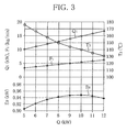
- FIG. 3 is an example of a characteristic graph showing recovered energy E R , heat radiation amount Q 1 in the condenser 22, or condenser output Q 1 , expander-inlet refrigerant temperature T 3 detected by the expander inlet temperature sensor 40, and flow rate F 1 of refrigerant entering the evaporator 10, with respect to evaporator input Q. It is obvious from FIG. 3 that, for example, the recovered energy E R reaches a maximum value of about 0.95 kW when the evaporator input Q is about 10 kW, and that the expander inlet temperature T 3 at this time point is about 140°C. As a maximum heat absorption amount of the evaporator 10, at least a value of about 10 kW is required.
- the expander-inlet refrigerant temperature T 3 is maintained lower than 150°C by carrying out S1 of the Rankine cycle control. This makes it possible to maintain the evaporator input Q at about 8 kW and simultaneously obtain the recovered energy E R of about 0.945 kW.
- the decrease of the evaporator input Q is about 2 kW, and decrease rate thereof is about 20%.
- the decrease of the recovered energy E R is about 0.005 kW, and decrease rate thereof is only about 0.5%.
- the decrease of the evaporator input Q causes a decrease in the condenser output Q 1 and a drop in the refrigerant condensation temperature T 4 in the condenser 22, resulting in an increase in the refrigerant's expansion pressure ratio in the expander 20.
- Another reason is that enthalpy gradient during expansion is increased as a result of a rise in the expander inlet temperature. This makes it possible to reduce the maximum heat absorption amount of the evaporator 10 to a large degree in proportion to the decrease of the recovered energy E R . It is also possible to effectively increase the recovered energy E R while downsizing the evaporator 10.
- the condenser output Q 1 becomes large here because the evaporator input Q is too large. This case corresponds to when the engine 4 is under high load. Temperature difference between the evaporator-outlet refrigerant temperature T 5 and the condenser temperature T 4 becomes too small, and therefore, the output of the expander 20, or the recovered energy E R , tends to decrease. However, the evaporator input Q can be reduced by decreasing the flow rate of the refrigerant entering the evaporator 10. It is therefore possible to adjust the condenser output Q 1 to correspond to the heat capacity of the condenser 22 and thus more effectively increase the recovered energy E R .
- the evaporator input Q can be adjusted to correspond to the waste heat amount when the engine 4 is under low load by reducing the flow rate of the refrigerant entering the evaporator 10. It is accordingly possible to more effectively increase the recovered energy E R .
- a second embodiment will be described below with reference to a diagram of the waste heat utilization device 2 shown in FIG. 4 .
- the exhaust gas pipe 28 of the first embodiment is partitioned by a partition plate 52 into a heat exchange side 18a and a non-heat exchange side 18b with respect to the exhaust gas heat exchanger 18. This is to perform damper drive control that uses a damper 54 to direct exhaust gas to either the heat exchange side 18a or the non-heat exchange side 18b.
- the second embodiment has the same configuration as the first.
- the damper 54 is mounted on the engine 4-side end portion of the partition plate 52.
- a movable part 54a of the damper 54 is driven by a driving part 54b that is electrically connected to the ECU 32.
- the damper 54 thus can direct exhaust gas to either the heat exchange side 18a or the non-heat exchange side 18b.
- the ECU 32 carries out damper drive control that controls the damper 54 according to the expander-inlet refrigerant temperature T 3 detected by the expander inlet temperature sensor 40.
- the damper drive control will be described below with reference to the flowchart shown in FIG. 5 .
- S20 makes a determination as to whether the expander-inlet refrigerant temperature T 3 detected by the expander inlet temperature sensor 40 is lower than, for example, 175°C. If the result is YES, and it is determined that T 3 ⁇ 175°C is true, the routine moves to S21. If the result is NO, and it is determined that T 3 ⁇ 175°C is not true, the routine moves to S22. In this case, temperature at which the refrigerant circulating through the RC circuit 8 and the lubricant added to the refrigerant are surely prevented from being deteriorated and degraded is about 175°C.
- the damper 54 is driven to open the heat exchange side 18a and close the non-heat exchange side 18b in order to direct exhaust gas towards the exhaust gas heat exchanger 18 within the exhaust gas pipe 28.
- the control routine then returns to START.
- the damper 54 is driven to close the heat exchange side 18a and open the non-heat exchange side 18b in order to make exhaust gas flow in such a way that the exhaust gas bypasses the exhaust gas heat exchanger 18 within the exhaust gas pipe 28.
- the control routine then returns to START.
- the present embodiment effectively increases the recovered energy E R and downsizes the evaporator 10 at the same time as in the first embodiment.
- the temperature at which the refrigerant circulating through the RC circuit 8 and the lubricant added to the refrigerant are surely prevented from being deteriorated and degraded is about 175°C. If the damper 54 is driven on the basis of this temperature, the refrigerant and the lubricant added to the refrigerant are prevented from being deteriorated. The recovered energy E R therefore can be surely increased.
- S8 makes a determination as to whether the flow rate F of the coolant flowing through the radiator 12, which is detected by the radiator passing-water flow-rate sensor 38, is zero.
- a temperature sensor may be disposed in the outlet of the radiator 12. In this case, too, a determination can be made from the coolant temperature as to whether there is the coolant flowing through the radiator 12.
- the embodiments detect the coolant and refrigerant temperatures in the Rankine cycle control.
- the coolant generally has a greater heat capacity than the refrigerant, so that there is a chance that control is delayed.
- the rotation frequency N 1 of the refrigerant pump 26 is increased or decreased according to the detected coolant temperatures T 1 and T 2 , the load of the engine 4 is estimated by the temperature of exhaust gas and the revolution of the engine 4. It is preferable that a control parameter of the Rankine cycle control is preset to early increase or decrease the rotation frequency N 1 of the refrigerant pump 26 according to a result of the estimation because, by so doing, the controllability of the Rankine cycle is further improved.
- the embodiments calculate the refrigerant's superheat level SH in the evaporator 10. If the evaporator outlet pressure sensor 44 and the evaporator outlet temperature sensor 46 are disposed as closely as possible to the exhaust gas heat exchanger 18, it is possible to calculate the superheat level SH reflecting a decrease in temperature of the refrigerant between the evaporator 10 and the exhaust gas heat exchanger 18.
- the heater 18 is described as an exhaust gas heat exchanger that directly heats the refrigerant by using the exhaust gas flowing through the exhaust gas pipe 28 of the engine 4.
- the heater 18 may be any heat exchanger as long as it heats the refrigerant leaving the evaporator 10 by using the exhaust gas of the engine 4.
- the invention may be applied to a circuit configuration in which an exhaust gas heat exchanger is placed in the coolant circuit 6, and the RC circuit 8 is provided with a superheater that carries out heat exchange between the coolant that has passed through the exhaust gas heat exchanger and the refrigerant that has passed through the evaporator 10 to bring the refrigerant into a superheated state, to thereby indirectly transmits exhaust gas heat to the refrigerant through the superheater.
Applications Claiming Priority (2)
| Application Number | Priority Date | Filing Date | Title |
|---|---|---|---|
| JP2008033024 | 2008-02-14 | ||
| PCT/JP2009/052310 WO2009101977A1 (ja) | 2008-02-14 | 2009-02-12 | 内燃機関の廃熱利用装置 |
Publications (3)
| Publication Number | Publication Date |
|---|---|
| EP2249017A1 true EP2249017A1 (de) | 2010-11-10 |
| EP2249017A4 EP2249017A4 (de) | 2011-03-23 |
| EP2249017B1 EP2249017B1 (de) | 2013-03-27 |
Family
ID=40957007
Family Applications (1)
| Application Number | Title | Priority Date | Filing Date |
|---|---|---|---|
| EP09711518A Active EP2249017B1 (de) | 2008-02-14 | 2009-02-12 | Abwärme nutzende vorrichtung für einen verbrennungsmotor |
Country Status (4)
| Country | Link |
|---|---|
| US (1) | US9441576B2 (de) |
| EP (1) | EP2249017B1 (de) |
| JP (1) | JP5281587B2 (de) |
| WO (1) | WO2009101977A1 (de) |
Cited By (7)
| Publication number | Priority date | Publication date | Assignee | Title |
|---|---|---|---|---|
| WO2010130317A3 (de) * | 2009-05-09 | 2011-10-13 | Daimler Ag | Abgaswärmenutzung in kraftfahrzeugen |
| WO2012074456A1 (en) | 2010-12-01 | 2012-06-07 | Scania Cv Ab | Arrangement and method for converting thermal energy to mechanical energy |
| WO2013007530A1 (de) | 2011-07-14 | 2013-01-17 | Avl List Gmbh | Verfahren zur regelung einer wärmenutzungsvorrichtung bei einer brennkraftmaschine |
| CN103423038A (zh) * | 2013-08-28 | 2013-12-04 | 曲有才 | 汽车汽油蒸发器及使用该汽油蒸发器的燃料输送装置 |
| EP2940254A4 (de) * | 2012-12-28 | 2016-11-16 | Mitsubishi Heavy Ind Ltd | Stromerzeugungssystem und stromerzeugungsverfahren |
| FR3040333A1 (fr) * | 2015-08-28 | 2017-03-03 | Valeo Systemes Thermiques | Circuit de gestion thermique d'un vehicule automobile comprenant une boucle de rankine et procede de pilotage associe |
| FR3040332A1 (fr) * | 2015-08-28 | 2017-03-03 | Valeo Systemes Thermiques | Circuit de gestion thermique d'un vehicule automobile comprenant une boucle de rankine et procede de pilotage associe |
Families Citing this family (38)
| Publication number | Priority date | Publication date | Assignee | Title |
|---|---|---|---|---|
| DE102007062580A1 (de) * | 2007-12-22 | 2009-06-25 | Daimler Ag | Verfahren zur Rückgewinnung einer Verlustwärme einer Verbrennungskraftmaschine |
| JP5476067B2 (ja) * | 2008-08-26 | 2014-04-23 | サンデン株式会社 | 内燃機関の廃熱利用装置 |
| JP5515591B2 (ja) * | 2009-10-07 | 2014-06-11 | 三菱電機株式会社 | 排熱回生システム |
| US20120000200A1 (en) * | 2010-06-30 | 2012-01-05 | General Electric Company | Inert gas purging system for an orc heat recovery boiler |
| JP5278496B2 (ja) * | 2011-03-25 | 2013-09-04 | 株式会社豊田自動織機 | 車両用排熱回収装置 |
| JP5621721B2 (ja) * | 2011-06-30 | 2014-11-12 | 株式会社豊田自動織機 | ランキンサイクル |
| JP2013011258A (ja) * | 2011-06-30 | 2013-01-17 | Toyota Industries Corp | ランキンサイクル |
| JP2014231737A (ja) * | 2011-09-22 | 2014-12-11 | 株式会社豊田自動織機 | ランキンサイクル装置 |
| CN103748347B (zh) | 2011-09-30 | 2015-08-19 | 日产自动车株式会社 | 朗肯循环 |
| US8931275B2 (en) * | 2012-01-24 | 2015-01-13 | GM Global Technology Operations LLC | Adaptive heat exchange architecture for optimum energy recovery in a waste heat recovery architecture |
| US9551487B2 (en) | 2012-03-06 | 2017-01-24 | Access Energy Llc | Heat recovery using radiant heat |
| JP2013217221A (ja) * | 2012-04-05 | 2013-10-24 | Toyota Industries Corp | ランキンサイクル装置 |
| JP6097115B2 (ja) * | 2012-05-09 | 2017-03-15 | サンデンホールディングス株式会社 | 排熱回収装置 |
| EP2847447B1 (de) * | 2012-05-10 | 2017-09-27 | Volvo Lastvagnar Ab | Verbrennungsmotoranordnung eines fahrzeuges mit wärmerückgewinnungssystem für abgaskomprimierung |
| US9322300B2 (en) * | 2012-07-24 | 2016-04-26 | Access Energy Llc | Thermal cycle energy and pumping recovery system |
| JP6049169B2 (ja) * | 2012-08-15 | 2016-12-21 | アドバンス理工株式会社 | 排熱発電システム |
| JP5891146B2 (ja) * | 2012-08-29 | 2016-03-22 | 株式会社神戸製鋼所 | 発電装置及び発電装置の制御方法 |
| JP5918117B2 (ja) * | 2012-12-18 | 2016-05-18 | 株式会社神戸製鋼所 | 発電装置 |
| DE102013001569A1 (de) | 2013-01-30 | 2014-07-31 | Daimler Ag | Verfahren zum Betreiben einer Abwärmenutzungsvorrichtung |
| US20140224469A1 (en) * | 2013-02-11 | 2014-08-14 | Access Energy Llc | Controlling heat source fluid for thermal cycles |
| US9540961B2 (en) | 2013-04-25 | 2017-01-10 | Access Energy Llc | Heat sources for thermal cycles |
| JP6194273B2 (ja) | 2014-04-04 | 2017-09-06 | 株式会社神戸製鋼所 | 排熱回収装置及び排熱回収方法 |
| US9874114B2 (en) * | 2014-07-17 | 2018-01-23 | Panasonic Intellectual Property Management Co., Ltd. | Cogenerating system |
| JP6315814B2 (ja) | 2014-09-17 | 2018-04-25 | 株式会社神戸製鋼所 | エネルギー回収装置及び圧縮装置並びにエネルギー回収方法 |
| JP6495608B2 (ja) * | 2014-10-09 | 2019-04-03 | サンデンホールディングス株式会社 | 廃熱回収装置 |
| JP6485688B2 (ja) * | 2014-12-25 | 2019-03-20 | パナソニックIpマネジメント株式会社 | 熱発電装置 |
| JP6489856B2 (ja) * | 2015-02-04 | 2019-03-27 | 三菱重工業株式会社 | 排熱回収装置、排熱回収型船舶推進装置および排熱回収方法 |
| KR101637811B1 (ko) * | 2015-02-09 | 2016-07-07 | 현대자동차주식회사 | 랭킨사이클 및 열전모듈을 이용한 냉방시스템 및 그 제어방법 |
| US20160252310A1 (en) * | 2015-02-27 | 2016-09-01 | Tenneco Automotive Operating Company Inc. | Waste Heat Recovery System |
| EP3118425B1 (de) * | 2015-07-16 | 2018-05-09 | Kabushiki Kaisha Kobe Seiko Sho (Kobe Steel, Ltd.) | Wärmeenergierückgewinnungsvorrichtung und anlaufverfahren dafür |
| CN105003351B (zh) | 2015-07-21 | 2016-08-17 | 天津大学 | 对气体机余热能进行梯级回收的多能量形式输出的能源塔 |
| CN105317584B (zh) * | 2015-11-12 | 2017-03-29 | 重庆长安汽车股份有限公司 | 汽车发动机能量回收系统及回收方法 |
| CN105862947A (zh) * | 2016-03-30 | 2016-08-17 | 时建华 | 一种基于热循环的桥梁施工装置 |
| CN105804132A (zh) * | 2016-03-30 | 2016-07-27 | 时建华 | 一种基于双介质循环的道路挖土装置 |
| US20180194196A1 (en) * | 2017-01-06 | 2018-07-12 | GM Global Technology Operations LLC | Systems and methods utilizing heat pumps to recover thermal energy from exhaust gas |
| SE541066C2 (en) * | 2017-06-16 | 2019-03-26 | Climeon Ab | System and method for eliminating the presence of droplets in a heat exchanger |
| SE542760C2 (en) | 2018-12-14 | 2020-07-07 | Climeon Ab | Method and controller for preventing formation of droplets in a heat exchanger |
| DE102019122087A1 (de) * | 2019-08-16 | 2021-02-18 | Anton Neukäufer | Energierückgewinnungsanlage mit Koppelkreislauf |
Citations (9)
| Publication number | Priority date | Publication date | Assignee | Title |
|---|---|---|---|---|
| JP2001027118A (ja) * | 1999-07-15 | 2001-01-30 | Nissan Motor Co Ltd | 内燃機関の廃熱回収装置 |
| WO2004033859A1 (de) * | 2002-10-11 | 2004-04-22 | Alpps Fuel Cell Systems Gmbh | Verfahren und einrichtung zur rückgewinnung von energie |
| FR2868809A1 (fr) * | 2004-04-09 | 2005-10-14 | Armines Ass Pour La Rech Et Le | Systeme permettant de recuperer l'energie thermique d'un vehicule a moteur thermique en mettant en oeuvre un cycle de rankine produisant de l'energie mecanique et/ou electrique au moyen d'une turbine |
| US20060201153A1 (en) * | 2005-03-09 | 2006-09-14 | Honda Motor Co., Ltd. | Rankine cycle system |
| FR2884556A1 (fr) * | 2005-04-13 | 2006-10-20 | Peugeot Citroen Automobiles Sa | Dispositif de recuperation d'energie d'un moteur a combustion interne |
| US20060254276A1 (en) * | 2005-03-11 | 2006-11-16 | Honda Motor Co., Ltd. | Rankine cycle system |
| DE102007033611A1 (de) * | 2007-07-17 | 2009-01-22 | Amovis Gmbh | Anordnung zur Abgaswärmenutzung |
| WO2010000284A2 (de) * | 2008-07-03 | 2010-01-07 | Fev Motorentechnik Gmbh | Abgasenergienutzung mittels geschlossenem dampfkraftprozess |
| DE102009024776A1 (de) * | 2009-06-10 | 2010-12-16 | Daimler Ag | Fahrzeug mit einem geschlossenen Fluidkreislauf |
Family Cites Families (20)
| Publication number | Priority date | Publication date | Assignee | Title |
|---|---|---|---|---|
| JPS5814404U (ja) * | 1981-07-22 | 1983-01-29 | 株式会社東芝 | ランキンサイクル装置 |
| US20040020206A1 (en) * | 2001-05-07 | 2004-02-05 | Sullivan Timothy J. | Heat energy utilization system |
| US20030213246A1 (en) * | 2002-05-15 | 2003-11-20 | Coll John Gordon | Process and device for controlling the thermal and electrical output of integrated micro combined heat and power generation systems |
| JP3901609B2 (ja) * | 2002-07-25 | 2007-04-04 | 本田技研工業株式会社 | ランキンサイクル装置 |
| KR100528392B1 (ko) * | 2003-01-27 | 2005-11-15 | 가부시키가이샤 덴소 | 냉동 사이클 및 랭킨 사이클을 갖는 증기-압축 냉동사이클 시스템 |
| JP4277608B2 (ja) * | 2003-07-10 | 2009-06-10 | 株式会社日本自動車部品総合研究所 | ランキンサイクル |
| JP4089619B2 (ja) * | 2004-01-13 | 2008-05-28 | 株式会社デンソー | ランキンサイクルシステム |
| DE102005024685A1 (de) * | 2004-05-31 | 2005-12-29 | Denso Corp., Kariya | Wärmekreis |
| JP2006046763A (ja) * | 2004-08-03 | 2006-02-16 | Denso Corp | 廃熱利用装置を備える冷凍装置 |
| JP2006144744A (ja) * | 2004-11-24 | 2006-06-08 | Toyota Industries Corp | 車両用排熱回収システム |
| JP4543920B2 (ja) * | 2004-12-22 | 2010-09-15 | 株式会社デンソー | 熱機関の廃熱利用装置 |
| JP2006200493A (ja) * | 2005-01-24 | 2006-08-03 | Honda Motor Co Ltd | ランキンサイクル装置 |
| JP4823936B2 (ja) * | 2006-04-19 | 2011-11-24 | 株式会社デンソー | 廃熱利用装置およびその制御方法 |
| JP4801810B2 (ja) * | 2006-05-30 | 2011-10-26 | 株式会社デンソー | 廃熱利用装置を備える冷凍装置 |
| JP2008231981A (ja) * | 2007-03-19 | 2008-10-02 | Sanden Corp | 内燃機関の廃熱利用装置 |
| JP2008255923A (ja) * | 2007-04-06 | 2008-10-23 | Sanden Corp | 内燃機関の廃熱利用装置 |
| JP5008441B2 (ja) * | 2007-04-09 | 2012-08-22 | サンデン株式会社 | 内燃機関の廃熱利用装置 |
| JP5090522B2 (ja) * | 2007-05-29 | 2012-12-05 | ユーティーシー パワー コーポレイション | ランキンサイクルパワープラント熱源制御 |
| US8186161B2 (en) * | 2007-12-14 | 2012-05-29 | General Electric Company | System and method for controlling an expansion system |
| WO2009133620A1 (ja) * | 2008-05-01 | 2009-11-05 | サンデン株式会社 | 内燃機関の廃熱利用装置 |
-
2009
- 2009-02-12 JP JP2009553441A patent/JP5281587B2/ja active Active
- 2009-02-12 US US12/867,681 patent/US9441576B2/en active Active
- 2009-02-12 EP EP09711518A patent/EP2249017B1/de active Active
- 2009-02-12 WO PCT/JP2009/052310 patent/WO2009101977A1/ja active Application Filing
Patent Citations (9)
| Publication number | Priority date | Publication date | Assignee | Title |
|---|---|---|---|---|
| JP2001027118A (ja) * | 1999-07-15 | 2001-01-30 | Nissan Motor Co Ltd | 内燃機関の廃熱回収装置 |
| WO2004033859A1 (de) * | 2002-10-11 | 2004-04-22 | Alpps Fuel Cell Systems Gmbh | Verfahren und einrichtung zur rückgewinnung von energie |
| FR2868809A1 (fr) * | 2004-04-09 | 2005-10-14 | Armines Ass Pour La Rech Et Le | Systeme permettant de recuperer l'energie thermique d'un vehicule a moteur thermique en mettant en oeuvre un cycle de rankine produisant de l'energie mecanique et/ou electrique au moyen d'une turbine |
| US20060201153A1 (en) * | 2005-03-09 | 2006-09-14 | Honda Motor Co., Ltd. | Rankine cycle system |
| US20060254276A1 (en) * | 2005-03-11 | 2006-11-16 | Honda Motor Co., Ltd. | Rankine cycle system |
| FR2884556A1 (fr) * | 2005-04-13 | 2006-10-20 | Peugeot Citroen Automobiles Sa | Dispositif de recuperation d'energie d'un moteur a combustion interne |
| DE102007033611A1 (de) * | 2007-07-17 | 2009-01-22 | Amovis Gmbh | Anordnung zur Abgaswärmenutzung |
| WO2010000284A2 (de) * | 2008-07-03 | 2010-01-07 | Fev Motorentechnik Gmbh | Abgasenergienutzung mittels geschlossenem dampfkraftprozess |
| DE102009024776A1 (de) * | 2009-06-10 | 2010-12-16 | Daimler Ag | Fahrzeug mit einem geschlossenen Fluidkreislauf |
Non-Patent Citations (1)
| Title |
|---|
| See also references of WO2009101977A1 * |
Cited By (9)
| Publication number | Priority date | Publication date | Assignee | Title |
|---|---|---|---|---|
| WO2010130317A3 (de) * | 2009-05-09 | 2011-10-13 | Daimler Ag | Abgaswärmenutzung in kraftfahrzeugen |
| WO2012074456A1 (en) | 2010-12-01 | 2012-06-07 | Scania Cv Ab | Arrangement and method for converting thermal energy to mechanical energy |
| EP2646672A1 (de) * | 2010-12-01 | 2013-10-09 | Scania CV AB | Anordnung und verfahren zur umwandlung von wärmeenergie in mechanische energie |
| EP2646672A4 (de) * | 2010-12-01 | 2014-07-30 | Scania Cv Ab | Anordnung und verfahren zur umwandlung von wärmeenergie in mechanische energie |
| WO2013007530A1 (de) | 2011-07-14 | 2013-01-17 | Avl List Gmbh | Verfahren zur regelung einer wärmenutzungsvorrichtung bei einer brennkraftmaschine |
| EP2940254A4 (de) * | 2012-12-28 | 2016-11-16 | Mitsubishi Heavy Ind Ltd | Stromerzeugungssystem und stromerzeugungsverfahren |
| CN103423038A (zh) * | 2013-08-28 | 2013-12-04 | 曲有才 | 汽车汽油蒸发器及使用该汽油蒸发器的燃料输送装置 |
| FR3040333A1 (fr) * | 2015-08-28 | 2017-03-03 | Valeo Systemes Thermiques | Circuit de gestion thermique d'un vehicule automobile comprenant une boucle de rankine et procede de pilotage associe |
| FR3040332A1 (fr) * | 2015-08-28 | 2017-03-03 | Valeo Systemes Thermiques | Circuit de gestion thermique d'un vehicule automobile comprenant une boucle de rankine et procede de pilotage associe |
Also Published As
| Publication number | Publication date |
|---|---|
| EP2249017A4 (de) | 2011-03-23 |
| US20100307155A1 (en) | 2010-12-09 |
| WO2009101977A1 (ja) | 2009-08-20 |
| EP2249017B1 (de) | 2013-03-27 |
| US9441576B2 (en) | 2016-09-13 |
| JP5281587B2 (ja) | 2013-09-04 |
| JPWO2009101977A1 (ja) | 2011-06-09 |
Similar Documents
| Publication | Publication Date | Title |
|---|---|---|
| EP2249017B1 (de) | Abwärme nutzende vorrichtung für einen verbrennungsmotor | |
| US20110041505A1 (en) | Waste Heat Utilization Device for Internal Combustion Engine | |
| JP5053922B2 (ja) | 内燃機関の廃熱利用装置 | |
| JP5476067B2 (ja) | 内燃機関の廃熱利用装置 | |
| US8959914B2 (en) | Waste heat utilization device for internal combustion engine | |
| US8333068B2 (en) | Exhaust heat recovery device | |
| US20070245737A1 (en) | Waste heat utilization device and control method thereof | |
| US8613193B2 (en) | Vehicle waste heat recovery device | |
| US20110088397A1 (en) | Waste heat recovery system | |
| US9771835B2 (en) | Flow rate control of heat energy recovery device including oil separator | |
| JP2009287433A (ja) | 内燃機関の廃熱利用装置 | |
| US20130025277A1 (en) | Waste heat regeneration system | |
| US20130014505A1 (en) | Waste heat regeneration system | |
| JP2008231981A (ja) | 内燃機関の廃熱利用装置 | |
| JP5008441B2 (ja) | 内燃機関の廃熱利用装置 | |
| KR20110041392A (ko) | 폐열 회생 시스템 | |
| JP2005201067A (ja) | ランキンサイクルシステム | |
| JP6143755B2 (ja) | エンジンの廃熱利用装置 | |
| JP4588644B2 (ja) | 廃熱利用装置を備える冷凍装置 | |
| JP2009133266A (ja) | 内燃機関の廃熱利用装置 | |
| JP2011027000A (ja) | 廃熱利用装置 | |
| WO2009125276A1 (en) | Engine waste heat collection system | |
| JP4699972B2 (ja) | 廃熱利用装置およびその制御方法 | |
| JP6379633B2 (ja) | エンジン駆動式空気調和機 | |
| JP7056253B2 (ja) | ランキンサイクルシステム、及び、ランキンサイクルシステムの制御方法 |
Legal Events
| Date | Code | Title | Description |
|---|---|---|---|
| PUAI | Public reference made under article 153(3) epc to a published international application that has entered the european phase |
Free format text: ORIGINAL CODE: 0009012 |
|
| 17P | Request for examination filed |
Effective date: 20100812 |
|
| AK | Designated contracting states |
Kind code of ref document: A1 Designated state(s): AT BE BG CH CY CZ DE DK EE ES FI FR GB GR HR HU IE IS IT LI LT LU LV MC MK MT NL NO PL PT RO SE SI SK TR |
|
| AX | Request for extension of the european patent |
Extension state: AL BA RS |
|
| A4 | Supplementary search report drawn up and despatched |
Effective date: 20110221 |
|
| DAX | Request for extension of the european patent (deleted) | ||
| 17Q | First examination report despatched |
Effective date: 20120223 |
|
| GRAP | Despatch of communication of intention to grant a patent |
Free format text: ORIGINAL CODE: EPIDOSNIGR1 |
|
| GRAS | Grant fee paid |
Free format text: ORIGINAL CODE: EPIDOSNIGR3 |
|
| GRAA | (expected) grant |
Free format text: ORIGINAL CODE: 0009210 |
|
| AK | Designated contracting states |
Kind code of ref document: B1 Designated state(s): AT BE BG CH CY CZ DE DK EE ES FI FR GB GR HR HU IE IS IT LI LT LU LV MC MK MT NL NO PL PT RO SE SI SK TR |
|
| REG | Reference to a national code |
Ref country code: GB Ref legal event code: FG4D |
|
| REG | Reference to a national code |
Ref country code: CH Ref legal event code: EP |
|
| REG | Reference to a national code |
Ref country code: AT Ref legal event code: REF Ref document number: 603558 Country of ref document: AT Kind code of ref document: T Effective date: 20130415 |
|
| REG | Reference to a national code |
Ref country code: IE Ref legal event code: FG4D |
|
| REG | Reference to a national code |
Ref country code: DE Ref legal event code: R096 Ref document number: 602009014377 Country of ref document: DE Effective date: 20130529 |
|
| PG25 | Lapsed in a contracting state [announced via postgrant information from national office to epo] |
Ref country code: NO Free format text: LAPSE BECAUSE OF FAILURE TO SUBMIT A TRANSLATION OF THE DESCRIPTION OR TO PAY THE FEE WITHIN THE PRESCRIBED TIME-LIMIT Effective date: 20130627 Ref country code: LT Free format text: LAPSE BECAUSE OF FAILURE TO SUBMIT A TRANSLATION OF THE DESCRIPTION OR TO PAY THE FEE WITHIN THE PRESCRIBED TIME-LIMIT Effective date: 20130327 Ref country code: SE Free format text: LAPSE BECAUSE OF FAILURE TO SUBMIT A TRANSLATION OF THE DESCRIPTION OR TO PAY THE FEE WITHIN THE PRESCRIBED TIME-LIMIT Effective date: 20130327 Ref country code: BG Free format text: LAPSE BECAUSE OF FAILURE TO SUBMIT A TRANSLATION OF THE DESCRIPTION OR TO PAY THE FEE WITHIN THE PRESCRIBED TIME-LIMIT Effective date: 20130627 |
|
| REG | Reference to a national code |
Ref country code: AT Ref legal event code: MK05 Ref document number: 603558 Country of ref document: AT Kind code of ref document: T Effective date: 20130327 |
|
| REG | Reference to a national code |
Ref country code: LT Ref legal event code: MG4D |
|
| PG25 | Lapsed in a contracting state [announced via postgrant information from national office to epo] |
Ref country code: FI Free format text: LAPSE BECAUSE OF FAILURE TO SUBMIT A TRANSLATION OF THE DESCRIPTION OR TO PAY THE FEE WITHIN THE PRESCRIBED TIME-LIMIT Effective date: 20130327 Ref country code: LV Free format text: LAPSE BECAUSE OF FAILURE TO SUBMIT A TRANSLATION OF THE DESCRIPTION OR TO PAY THE FEE WITHIN THE PRESCRIBED TIME-LIMIT Effective date: 20130327 Ref country code: SI Free format text: LAPSE BECAUSE OF FAILURE TO SUBMIT A TRANSLATION OF THE DESCRIPTION OR TO PAY THE FEE WITHIN THE PRESCRIBED TIME-LIMIT Effective date: 20130327 Ref country code: GR Free format text: LAPSE BECAUSE OF FAILURE TO SUBMIT A TRANSLATION OF THE DESCRIPTION OR TO PAY THE FEE WITHIN THE PRESCRIBED TIME-LIMIT Effective date: 20130628 |
|
| REG | Reference to a national code |
Ref country code: NL Ref legal event code: VDEP Effective date: 20130327 |
|
| PG25 | Lapsed in a contracting state [announced via postgrant information from national office to epo] |
Ref country code: BE Free format text: LAPSE BECAUSE OF FAILURE TO SUBMIT A TRANSLATION OF THE DESCRIPTION OR TO PAY THE FEE WITHIN THE PRESCRIBED TIME-LIMIT Effective date: 20130327 Ref country code: HR Free format text: LAPSE BECAUSE OF FAILURE TO SUBMIT A TRANSLATION OF THE DESCRIPTION OR TO PAY THE FEE WITHIN THE PRESCRIBED TIME-LIMIT Effective date: 20130327 |
|
| PG25 | Lapsed in a contracting state [announced via postgrant information from national office to epo] |
Ref country code: SK Free format text: LAPSE BECAUSE OF FAILURE TO SUBMIT A TRANSLATION OF THE DESCRIPTION OR TO PAY THE FEE WITHIN THE PRESCRIBED TIME-LIMIT Effective date: 20130327 Ref country code: EE Free format text: LAPSE BECAUSE OF FAILURE TO SUBMIT A TRANSLATION OF THE DESCRIPTION OR TO PAY THE FEE WITHIN THE PRESCRIBED TIME-LIMIT Effective date: 20130327 Ref country code: CZ Free format text: LAPSE BECAUSE OF FAILURE TO SUBMIT A TRANSLATION OF THE DESCRIPTION OR TO PAY THE FEE WITHIN THE PRESCRIBED TIME-LIMIT Effective date: 20130327 Ref country code: RO Free format text: LAPSE BECAUSE OF FAILURE TO SUBMIT A TRANSLATION OF THE DESCRIPTION OR TO PAY THE FEE WITHIN THE PRESCRIBED TIME-LIMIT Effective date: 20130327 Ref country code: NL Free format text: LAPSE BECAUSE OF FAILURE TO SUBMIT A TRANSLATION OF THE DESCRIPTION OR TO PAY THE FEE WITHIN THE PRESCRIBED TIME-LIMIT Effective date: 20130327 Ref country code: ES Free format text: LAPSE BECAUSE OF FAILURE TO SUBMIT A TRANSLATION OF THE DESCRIPTION OR TO PAY THE FEE WITHIN THE PRESCRIBED TIME-LIMIT Effective date: 20130708 Ref country code: PT Free format text: LAPSE BECAUSE OF FAILURE TO SUBMIT A TRANSLATION OF THE DESCRIPTION OR TO PAY THE FEE WITHIN THE PRESCRIBED TIME-LIMIT Effective date: 20130729 Ref country code: IS Free format text: LAPSE BECAUSE OF FAILURE TO SUBMIT A TRANSLATION OF THE DESCRIPTION OR TO PAY THE FEE WITHIN THE PRESCRIBED TIME-LIMIT Effective date: 20130727 Ref country code: AT Free format text: LAPSE BECAUSE OF FAILURE TO SUBMIT A TRANSLATION OF THE DESCRIPTION OR TO PAY THE FEE WITHIN THE PRESCRIBED TIME-LIMIT Effective date: 20130327 |
|
| PG25 | Lapsed in a contracting state [announced via postgrant information from national office to epo] |
Ref country code: CY Free format text: LAPSE BECAUSE OF FAILURE TO SUBMIT A TRANSLATION OF THE DESCRIPTION OR TO PAY THE FEE WITHIN THE PRESCRIBED TIME-LIMIT Effective date: 20130327 Ref country code: PL Free format text: LAPSE BECAUSE OF FAILURE TO SUBMIT A TRANSLATION OF THE DESCRIPTION OR TO PAY THE FEE WITHIN THE PRESCRIBED TIME-LIMIT Effective date: 20130327 |
|
| PG25 | Lapsed in a contracting state [announced via postgrant information from national office to epo] |
Ref country code: DK Free format text: LAPSE BECAUSE OF FAILURE TO SUBMIT A TRANSLATION OF THE DESCRIPTION OR TO PAY THE FEE WITHIN THE PRESCRIBED TIME-LIMIT Effective date: 20130327 |
|
| PLBE | No opposition filed within time limit |
Free format text: ORIGINAL CODE: 0009261 |
|
| STAA | Information on the status of an ep patent application or granted ep patent |
Free format text: STATUS: NO OPPOSITION FILED WITHIN TIME LIMIT |
|
| 26N | No opposition filed |
Effective date: 20140103 |
|
| REG | Reference to a national code |
Ref country code: DE Ref legal event code: R097 Ref document number: 602009014377 Country of ref document: DE Effective date: 20140103 |
|
| PG25 | Lapsed in a contracting state [announced via postgrant information from national office to epo] |
Ref country code: MC Free format text: LAPSE BECAUSE OF FAILURE TO SUBMIT A TRANSLATION OF THE DESCRIPTION OR TO PAY THE FEE WITHIN THE PRESCRIBED TIME-LIMIT Effective date: 20130327 Ref country code: LU Free format text: LAPSE BECAUSE OF FAILURE TO SUBMIT A TRANSLATION OF THE DESCRIPTION OR TO PAY THE FEE WITHIN THE PRESCRIBED TIME-LIMIT Effective date: 20140212 |
|
| REG | Reference to a national code |
Ref country code: CH Ref legal event code: PL |
|
| PG25 | Lapsed in a contracting state [announced via postgrant information from national office to epo] |
Ref country code: CH Free format text: LAPSE BECAUSE OF NON-PAYMENT OF DUE FEES Effective date: 20140228 Ref country code: LI Free format text: LAPSE BECAUSE OF NON-PAYMENT OF DUE FEES Effective date: 20140228 |
|
| REG | Reference to a national code |
Ref country code: IE Ref legal event code: MM4A |
|
| PG25 | Lapsed in a contracting state [announced via postgrant information from national office to epo] |
Ref country code: IE Free format text: LAPSE BECAUSE OF NON-PAYMENT OF DUE FEES Effective date: 20140212 |
|
| REG | Reference to a national code |
Ref country code: FR Ref legal event code: PLFP Year of fee payment: 8 |
|
| PG25 | Lapsed in a contracting state [announced via postgrant information from national office to epo] |
Ref country code: MT Free format text: LAPSE BECAUSE OF FAILURE TO SUBMIT A TRANSLATION OF THE DESCRIPTION OR TO PAY THE FEE WITHIN THE PRESCRIBED TIME-LIMIT Effective date: 20130327 |
|
| REG | Reference to a national code |
Ref country code: DE Ref legal event code: R082 Ref document number: 602009014377 Country of ref document: DE Representative=s name: PRUEFER & PARTNER MBB PATENTANWAELTE RECHTSANW, DE Ref country code: DE Ref legal event code: R081 Ref document number: 602009014377 Country of ref document: DE Owner name: SANDEN HOLDINGS CORPORATION, LSESAKI-SHI, JP Free format text: FORMER OWNER: SANDEN CORP., ISESAKI, GUNMA, JP |
|
| PGFP | Annual fee paid to national office [announced via postgrant information from national office to epo] |
Ref country code: IT Payment date: 20160223 Year of fee payment: 8 |
|
| PGFP | Annual fee paid to national office [announced via postgrant information from national office to epo] |
Ref country code: GB Payment date: 20160217 Year of fee payment: 8 Ref country code: FR Payment date: 20160218 Year of fee payment: 8 |
|
| REG | Reference to a national code |
Ref country code: FR Ref legal event code: CD Owner name: SANDEN HOLDINGS CORPORATION, JP Effective date: 20160525 |
|
| PG25 | Lapsed in a contracting state [announced via postgrant information from national office to epo] |
Ref country code: HU Free format text: LAPSE BECAUSE OF FAILURE TO SUBMIT A TRANSLATION OF THE DESCRIPTION OR TO PAY THE FEE WITHIN THE PRESCRIBED TIME-LIMIT; INVALID AB INITIO Effective date: 20090212 Ref country code: TR Free format text: LAPSE BECAUSE OF FAILURE TO SUBMIT A TRANSLATION OF THE DESCRIPTION OR TO PAY THE FEE WITHIN THE PRESCRIBED TIME-LIMIT Effective date: 20130327 |
|
| GBPC | Gb: european patent ceased through non-payment of renewal fee |
Effective date: 20170212 |
|
| REG | Reference to a national code |
Ref country code: FR Ref legal event code: ST Effective date: 20171031 |
|
| PG25 | Lapsed in a contracting state [announced via postgrant information from national office to epo] |
Ref country code: FR Free format text: LAPSE BECAUSE OF NON-PAYMENT OF DUE FEES Effective date: 20170228 |
|
| PG25 | Lapsed in a contracting state [announced via postgrant information from national office to epo] |
Ref country code: GB Free format text: LAPSE BECAUSE OF NON-PAYMENT OF DUE FEES Effective date: 20170212 Ref country code: IT Free format text: LAPSE BECAUSE OF NON-PAYMENT OF DUE FEES Effective date: 20170212 |
|
| PG25 | Lapsed in a contracting state [announced via postgrant information from national office to epo] |
Ref country code: MK Free format text: LAPSE BECAUSE OF FAILURE TO SUBMIT A TRANSLATION OF THE DESCRIPTION OR TO PAY THE FEE WITHIN THE PRESCRIBED TIME-LIMIT Effective date: 20130327 |
|
| REG | Reference to a national code |
Ref country code: DE Ref legal event code: R081 Ref document number: 602009014377 Country of ref document: DE Owner name: SANDEN CORPORATION, ISESAKI-SHI, JP Free format text: FORMER OWNER: SANDEN HOLDINGS CORPORATION, LSESAKI-SHI, GUNMA, JP |
|
| PGFP | Annual fee paid to national office [announced via postgrant information from national office to epo] |
Ref country code: DE Payment date: 20230119 Year of fee payment: 15 |