EP2247819B1 - Verfahren und vorrichtung für die vorortprüfung von gasströmungssteuerungen - Google Patents
Verfahren und vorrichtung für die vorortprüfung von gasströmungssteuerungen Download PDFInfo
- Publication number
- EP2247819B1 EP2247819B1 EP09702610.8A EP09702610A EP2247819B1 EP 2247819 B1 EP2247819 B1 EP 2247819B1 EP 09702610 A EP09702610 A EP 09702610A EP 2247819 B1 EP2247819 B1 EP 2247819B1
- Authority
- EP
- European Patent Office
- Prior art keywords
- pressure
- gas
- gfc
- gas flow
- valve
- Prior art date
- Legal status (The legal status is an assumption and is not a legal conclusion. Google has not performed a legal analysis and makes no representation as to the accuracy of the status listed.)
- Active
Links
- 238000000034 method Methods 0.000 title claims description 84
- 238000012360 testing method Methods 0.000 title description 26
- 238000011065 in-situ storage Methods 0.000 title 1
- 230000008569 process Effects 0.000 claims description 46
- 238000011144 upstream manufacturing Methods 0.000 claims description 33
- 238000012545 processing Methods 0.000 claims description 20
- 239000007789 gas Substances 0.000 description 172
- 238000005259 measurement Methods 0.000 description 71
- 238000013459 approach Methods 0.000 description 19
- 230000008859 change Effects 0.000 description 17
- 239000004065 semiconductor Substances 0.000 description 17
- 238000004519 manufacturing process Methods 0.000 description 15
- 238000010586 diagram Methods 0.000 description 14
- 230000008901 benefit Effects 0.000 description 9
- 239000012530 fluid Substances 0.000 description 9
- 238000004891 communication Methods 0.000 description 8
- 238000009428 plumbing Methods 0.000 description 8
- 230000007423 decrease Effects 0.000 description 7
- 230000006641 stabilisation Effects 0.000 description 6
- 238000011105 stabilization Methods 0.000 description 6
- 230000001276 controlling effect Effects 0.000 description 5
- 230000004044 response Effects 0.000 description 5
- 238000012956 testing procedure Methods 0.000 description 5
- 230000001052 transient effect Effects 0.000 description 5
- IJGRMHOSHXDMSA-UHFFFAOYSA-N Atomic nitrogen Chemical compound N#N IJGRMHOSHXDMSA-UHFFFAOYSA-N 0.000 description 4
- XUIMIQQOPSSXEZ-UHFFFAOYSA-N Silicon Chemical compound [Si] XUIMIQQOPSSXEZ-UHFFFAOYSA-N 0.000 description 3
- 238000009530 blood pressure measurement Methods 0.000 description 3
- 238000012937 correction Methods 0.000 description 3
- 238000003780 insertion Methods 0.000 description 3
- 230000037431 insertion Effects 0.000 description 3
- 239000007788 liquid Substances 0.000 description 3
- 229910052710 silicon Inorganic materials 0.000 description 3
- 239000010703 silicon Substances 0.000 description 3
- 235000012431 wafers Nutrition 0.000 description 3
- QGZKDVFQNNGYKY-UHFFFAOYSA-N Ammonia Chemical compound N QGZKDVFQNNGYKY-UHFFFAOYSA-N 0.000 description 2
- 230000002411 adverse Effects 0.000 description 2
- 230000000694 effects Effects 0.000 description 2
- 230000000977 initiatory effect Effects 0.000 description 2
- 238000012544 monitoring process Methods 0.000 description 2
- 229910052757 nitrogen Inorganic materials 0.000 description 2
- 238000001020 plasma etching Methods 0.000 description 2
- 238000003860 storage Methods 0.000 description 2
- 230000000007 visual effect Effects 0.000 description 2
- UFHFLCQGNIYNRP-UHFFFAOYSA-N Hydrogen Chemical compound [H][H] UFHFLCQGNIYNRP-UHFFFAOYSA-N 0.000 description 1
- BLRPTPMANUNPDV-UHFFFAOYSA-N Silane Chemical compound [SiH4] BLRPTPMANUNPDV-UHFFFAOYSA-N 0.000 description 1
- 229910003074 TiCl4 Inorganic materials 0.000 description 1
- 229910021529 ammonia Inorganic materials 0.000 description 1
- 238000006243 chemical reaction Methods 0.000 description 1
- 230000003749 cleanliness Effects 0.000 description 1
- 230000003247 decreasing effect Effects 0.000 description 1
- 238000005137 deposition process Methods 0.000 description 1
- 238000013461 design Methods 0.000 description 1
- 230000006866 deterioration Effects 0.000 description 1
- 230000005284 excitation Effects 0.000 description 1
- 230000001747 exhibiting effect Effects 0.000 description 1
- 239000001257 hydrogen Substances 0.000 description 1
- 229910052739 hydrogen Inorganic materials 0.000 description 1
- 238000012625 in-situ measurement Methods 0.000 description 1
- 238000010348 incorporation Methods 0.000 description 1
- 238000009434 installation Methods 0.000 description 1
- 238000012423 maintenance Methods 0.000 description 1
- 239000000463 material Substances 0.000 description 1
- 238000000691 measurement method Methods 0.000 description 1
- 239000012528 membrane Substances 0.000 description 1
- 230000003278 mimic effect Effects 0.000 description 1
- 230000001105 regulatory effect Effects 0.000 description 1
- 238000005070 sampling Methods 0.000 description 1
- 229910000077 silane Inorganic materials 0.000 description 1
- XJDNKRIXUMDJCW-UHFFFAOYSA-J titanium tetrachloride Chemical compound Cl[Ti](Cl)(Cl)Cl XJDNKRIXUMDJCW-UHFFFAOYSA-J 0.000 description 1
- 230000007704 transition Effects 0.000 description 1
- XLYOFNOQVPJJNP-UHFFFAOYSA-N water Substances O XLYOFNOQVPJJNP-UHFFFAOYSA-N 0.000 description 1
Images


Classifications
-
- G—PHYSICS
- G01—MEASURING; TESTING
- G01F—MEASURING VOLUME, VOLUME FLOW, MASS FLOW OR LIQUID LEVEL; METERING BY VOLUME
- G01F25/00—Testing or calibration of apparatus for measuring volume, volume flow or liquid level or for metering by volume
- G01F25/10—Testing or calibration of apparatus for measuring volume, volume flow or liquid level or for metering by volume of flowmeters
- G01F25/17—Testing or calibration of apparatus for measuring volume, volume flow or liquid level or for metering by volume of flowmeters using calibrated reservoirs
-
- G—PHYSICS
- G01—MEASURING; TESTING
- G01F—MEASURING VOLUME, VOLUME FLOW, MASS FLOW OR LIQUID LEVEL; METERING BY VOLUME
- G01F25/00—Testing or calibration of apparatus for measuring volume, volume flow or liquid level or for metering by volume
- G01F25/10—Testing or calibration of apparatus for measuring volume, volume flow or liquid level or for metering by volume of flowmeters
- G01F25/15—Testing or calibration of apparatus for measuring volume, volume flow or liquid level or for metering by volume of flowmeters specially adapted for gas meters
-
- Y—GENERAL TAGGING OF NEW TECHNOLOGICAL DEVELOPMENTS; GENERAL TAGGING OF CROSS-SECTIONAL TECHNOLOGIES SPANNING OVER SEVERAL SECTIONS OF THE IPC; TECHNICAL SUBJECTS COVERED BY FORMER USPC CROSS-REFERENCE ART COLLECTIONS [XRACs] AND DIGESTS
- Y10—TECHNICAL SUBJECTS COVERED BY FORMER USPC
- Y10T—TECHNICAL SUBJECTS COVERED BY FORMER US CLASSIFICATION
- Y10T137/00—Fluid handling
- Y10T137/0318—Processes
- Y10T137/0324—With control of flow by a condition or characteristic of a fluid
- Y10T137/0379—By fluid pressure
-
- Y—GENERAL TAGGING OF NEW TECHNOLOGICAL DEVELOPMENTS; GENERAL TAGGING OF CROSS-SECTIONAL TECHNOLOGIES SPANNING OVER SEVERAL SECTIONS OF THE IPC; TECHNICAL SUBJECTS COVERED BY FORMER USPC CROSS-REFERENCE ART COLLECTIONS [XRACs] AND DIGESTS
- Y10—TECHNICAL SUBJECTS COVERED BY FORMER USPC
- Y10T—TECHNICAL SUBJECTS COVERED BY FORMER US CLASSIFICATION
- Y10T137/00—Fluid handling
- Y10T137/7722—Line condition change responsive valves
- Y10T137/7758—Pilot or servo controlled
- Y10T137/7759—Responsive to change in rate of fluid flow
-
- Y—GENERAL TAGGING OF NEW TECHNOLOGICAL DEVELOPMENTS; GENERAL TAGGING OF CROSS-SECTIONAL TECHNOLOGIES SPANNING OVER SEVERAL SECTIONS OF THE IPC; TECHNICAL SUBJECTS COVERED BY FORMER USPC CROSS-REFERENCE ART COLLECTIONS [XRACs] AND DIGESTS
- Y10—TECHNICAL SUBJECTS COVERED BY FORMER USPC
- Y10T—TECHNICAL SUBJECTS COVERED BY FORMER US CLASSIFICATION
- Y10T137/00—Fluid handling
- Y10T137/7722—Line condition change responsive valves
- Y10T137/7758—Pilot or servo controlled
- Y10T137/7761—Electrically actuated valve
-
- Y—GENERAL TAGGING OF NEW TECHNOLOGICAL DEVELOPMENTS; GENERAL TAGGING OF CROSS-SECTIONAL TECHNOLOGIES SPANNING OVER SEVERAL SECTIONS OF THE IPC; TECHNICAL SUBJECTS COVERED BY FORMER USPC CROSS-REFERENCE ART COLLECTIONS [XRACs] AND DIGESTS
- Y10—TECHNICAL SUBJECTS COVERED BY FORMER USPC
- Y10T—TECHNICAL SUBJECTS COVERED BY FORMER US CLASSIFICATION
- Y10T137/00—Fluid handling
- Y10T137/7722—Line condition change responsive valves
- Y10T137/7758—Pilot or servo controlled
- Y10T137/7762—Fluid pressure type
Definitions
- Certain industrial processes depend on well-controlled flows of gas.
- One example is in the field of semiconductor device manufacturing, which uses a wide variety of gases for processing silicon wafers into integrated circuits (ICs).
- Plasma etching is a particularly important semiconductor process that depends upon carefully controlled flows of a number of different gases.
- various gases are introduced into a vacuum chamber.
- Electrical power typically in the form of radio frequency excitation
- the reactive gas species etch patterns into the silicon wafer to define different components of the IC.
- MFCs electro-mechanical mass flow controllers
- Semiconductor fabrication processes are especially sensitive to these drifts, since variations as small as a few percent can severely degrade the performance of the integrated circuit. Accordingly, maintenance of stable gas flows may require frequent testing and calibration of the mass flow controllers.
- testing of the MFCs is accomplished by introducing the gas into a vacuum chamber of a known volume, while monitoring the pressure within that chamber. Based upon the known correlation between pressure, volume, and the mass of the gas introduced (which defines the number of molecules of the gas), the rise in pressure ("rate of rise") as the gas flows into the vacuum chamber can be monitored. This information regarding pressure change within the chamber can then be used to determine the actual flow rate of gas through the mass flow controller.
- the vacuum chamber often used for the measurement of gas flows is the process chamber itself.
- the volume of the process chamber can be measured, for example, by monitoring a rise in pressure as gas is flowed through an MFC that is known to be accurate. Then, measurement of gas flow through any of the mass flow controllers connected to the process chamber can be readily accomplished.
- moisture on the walls of the chamber could react with a gas being flowed (such as silane), producing another gas (such as hydrogen) that throws off the pressure change and hence the flow rate calculation.
- a gas being flowed such as silane
- another gas such as hydrogen
- ammonia bound to the chamber walls may react with TiCl 4 flowed into the chamber, throwing off a flow rate calculation.
- Still another potential disadvantage to the conventional approach for measuring gas flows is that any change to the volume of the process chamber will require another measurement of the chamber volume.
- a component such as a pressure gauge, can change the volume of the chamber, thereby causing the flow rate calculated from the rate of rise of pressure to be incorrect.
- a separate volume can be positioned upstream of the process chamber, where the rate of rise measurement can take place. Since this volume will not have the types of deposits present in the process chamber and since this volume will not change by having components removed from it or added to it, some of the disadvantages cited above are not present.
- This method still requires a separate step during which no productive processing can occur, and there is the possibility of the gas reacting with adsorbed species on the volume wall present from a previous gas.
- a refinement of this approach includes a heat conductive assembly inside the volume for maintaining a constant temperature as the gas flows into or out of the volume. In one approach the volume already present within the mass flow controller is used as the known volume, instead of a separate container.
- Yet another approach allows measurement of the gas flow while the gas continues to flow as a normal part of its process.
- a known volume and a valve are positioned upstream of a gas flow controller that is maintaining a constant gas flow. Closure of the valve while the gas flow controller is maintaining a constant gas flow creates a pressure drop in the volume, where the rate of the pressure drop is proportional to the gas flow rate.
- a pressure regulator may be installed upstream of the gas flow controller (or, as described below, upstream of a flow restriction) and downstream of a known volume and a valve to interrupt the gas flow.
- a pressure regulator may be installed upstream of the gas flow controller (or, as described below, upstream of a flow restriction) and downstream of a known volume and a valve to interrupt the gas flow.
- One of the disadvantages of such a solution is that the requirements on this pressure regulator are so rigorous that standard pressure regulators will not be adequate in this role.
- the function of a pressure regulator is to keep the downstream pressure constant while the upstream pressure can take on any value higher than the downstream pressure, in reality the downstream pressure is influenced by the upstream pressure.
- most regulators have some amount of hysteresis. Any change in pressure downstream of the pressure regulator will create errors in the measurement of the gas flow; consequently, these systems require highly sophisticated pressure regulators to work effectively.
- a sophisticated pressure regulator may actually be part of a mass flow controller, which is composed of the pressure regulator, pressure transducer, and a flow restrictor used as a critical orifice. In this case, it makes sense to use a known volume and a valve arrangement to test the gas flow rate, since the pressure regulator is already in place.
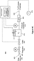
- Figure 1 shows an embodiment of an apparatus 100 representative of the prior art art as disclosed in US 6 363 958 B1 .
- the apparatus comprises a gas line 101 having an inlet 103 in fluid communication with a gas source 104, and an outlet 105 in fluid communication with either a flow restrictor or mass flow controller.
- the pressure regulator 102 is used to establish a constant pressure of the gas flowing to the flow restrictor or mass flow controller. Under standard process conditions, the valve 106 would be open and gas would be flowing through the pressure regulator to the flow restrictor or mass flow controller, and then ultimately into the process chamber.
- the volume V 110 represents the total fixed volume inside the pipes and other components present between the valve 106 and the gas flow controller (GFC), where the GFC can be, for example, a flow restrictor or mass flow controller (MFC).
- GFC gas flow controller
- MFC mass flow controller
- a pressure transducer 112 is configured to measure the pressure in the volume V 110 immediately upstream of the pressure regulator 102.
- the function of the pressure regulator 102 is to maintain a constant pressure downstream of the regulator regardless of the pressure upstream of the regulator (as long as the upstream pressure is equal to or larger than the downstream pressure). Under these conditions, there is no increase of decrease in the number of moles of gas between the pressure regulator and the flow restrictor or MFC. Consequently, the flow of gas out of the MFC or flow restrictor is equal to the flow of gas through the pressure regulator.
- valve 106 If valve 106 is closed, then since there is no gas entering or leaving the volume 110 from the left, any gas leaving the volume must flow through the pressure regulator 102, but since the flow through the pressure regulator is equal to the flow through the MFC or flow restrictor, the flow out of the volume is equal to the flow through the MFC or flow restrictor. Since the amount of gas leaving the volume 110 can be calculated from the rate of drop of pressure in the volume, such a calculation allows a determination of the flow rate through the flow restrictor or MFC.
- US 2003/234046 A1 discloses a self-calibrating mass flow controller, comprising a mass flow sensor configured to produce an electronic signal representative of mass flow in the mass flow controller as a function of the flow sensed by the sensor, a mass flow calibrator operative to produce an independent electronic signal representative of mass flow in the mass flow controller as a function of the flow sensed by the calibrator; and an electronic controller configured to correlate the mass flow signal from the thermal mass flow sensor to the rate of flow indicated by the independent electronic signal from the mass flow calibrator.
- the mass flow controller further comprises a valve operative to control the flow of gas in the mass flow controller under control of the electronic controller.
- a valve is a plumbing element used to shut off or turn on the flow of fluid.
- the on/off actions may be manual or automatic using some control scheme.
- a metering valve is a plumbing element that is used to shut off and fully or partially turn on the flow of fluid. This is a similar metering valve to that used in home water plumbing, where the user may turn the flow to a desired level.
- the on/off and partial on actions may be manual or automatic using some control scheme.
- a pressure regulator is a plumbing element that automatically cuts off the flow of fluid at a certain pressure at its output.
- Pressure regulators react to the pressure on their output side, and close when the pressure in the plumbing reaches the designated level. Should the pressure come down (for example, if someone were to open a faucet, i.e., open a metering valve downstream of the regulator), the regulator then opens and allows flow until the pressure is brought back up to its desired level, which is typically referred to as the set point.
- a typical pressure regulator uses the outside air, i.e., atmosphere, as a reference to bring the output (i.e., downstream) pressure to the desired set point. It regulates not on the pressure difference between the inlet and outlet, but rather the pressure difference between the outlet and the atmosphere.
- a method of determining a rate of flow of gas through a gas low controller comprises the features of claim 1
- an apparatus for determining a flow rate of a gas through a gas low controller comprises the features of claim 6.
- Embodiments of the present invention employ a rate of drop in pressure upstream of a GFC to accurately measure a rate of flow through the GFC; however, in contrast to the prior art, these embodiments allow measurement of the gas flow through the many gas flow controllers in production use today, without requiring any special or sophisticated pressure regulators or other special components.
- the timing of the closure of the valve is chosen such that none of the changes in pressure that occur during or after the measurement perturb the constant flow of gas through the GFC under test.
- the rise in pressure after the valve is reopened is controlled such that the constant flow of gas through the gas flow controller is not perturbed or not perturbed beyond a set level of 1%.
- the gas flow controller under test is replaced by a control valve that is in closed loop control with the measurement of the drop in pressure, such that the drop in pressure, and consequently the flow, is kept at a desired level.
- FIG. 2 shows an embodiment of an apparatus 200 for use in accordance with the present invention.
- the apparatus comprises a gas line 201 having an inlet 203 in fluid communication with a gas source 204, and an outlet 205 in fluid communication with a process chamber (not shown).
- the valve 206 would be open and gas would be flowing through the volume 210 to the gas flow controller (GFC) 208, and then ultimately into the process chamber.
- GFC gas flow controller
- the GFC which establishes the desired flow rate of gas to the process chamber, can be any one of several types of flow controllers typically employed in the semiconductor industry or in other fields. Most commonly, the GFC is a mass flow controller (MFC). Alternatively, the GFC can be a volumetric flow controller.
- MFC mass flow controller
- the GFC can be a volumetric flow controller.
- the volume V 210 represents the total fixed volume inside the pipes and other components present between the valve 206 and the GFC 208.
- a pressure transducer 212 is configured to measure the pressure in the volume V 210 immediately upstream of the GFC.
- a temperature sensor 214 is positioned to measure the temperature in the vicinity of the components.
- the sensor 214 may be a specialized sensor in direct thermal communication with one or more components.
- a thermometer positioned near the gas delivery system will provide sufficient information regarding the temperature of interest.
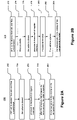
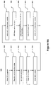
- the procedure for testing the flow of gas through the GFC may be summarized in the process flow 250 of FIG. 2A as follows.
- Step 5 can be done at any time during the testing procedure. In general, both for this procedure and others described below, this type of flexibility may be present.
- n PV / RT
- the compressibility factor may be determined from experimental measurements for any particular gas, and is a function of temperature and pressure.
- the first factor ( ⁇ P/ ⁇ t) is merely the slope of the pressure measurements as a function of time taken in step 3 of the procedure above.
- the actual rate of flow of the gas through the GFC can be determined according to embodiments of the present invention.
- a relative change in flow rate may be determined based upon a comparison of different pressure drop measurements.
- two sets of pressure drop measurements may be taken to provide a relative measure of changed flow rate.
- the first measurement may be taken from the GFC that is to be tested, with the second measurement taken from a GFC of known performance. A difference between the two pressure drop readings could reveal deviation of flow rate by the tested device, without determination of the actual flow rate.
- a first pressure drop measurement may be taken at a first time with the GFC that is to be tested, with the second pressure drop measurement being taken from that GFC at a second time.
- a difference between the two pressure drop measurements readings could reveal the magnitude of change (drift) in the flow rate from the tested device, over time.
- One or more steps of the various embodiments of the present invention could be performed with manual or automatic operation.
- the steps of opening/closing valves and taking pressure readings could be conducted automatically according to computer control.
- one or more of the various valves could be actuated manually, with the resulting flow rate calculated automatically from the detected pressure drop.
- Automatic operation of one or more steps could be accomplished based upon instructions stored in a computer readable storage medium, utilizing communication through control lines as indicated in Figures 1 and 2 .
- Another benefit of this measurement system is that if a discrepancy is found between the desired flow rate and the measured flow rate, the setting of the GFC could be changed to correct for the discrepancy and provide the desired flow rate. This correction could be done in the same process step or in a subsequent process step. This type of correction is greatly simplified if the system is under computer control.
- gas flow controllers particularly the MFCs used in the semiconductor industry, can accommodate slow changes in upstream pressure while still maintaining a constant flow rate; however, if the pressure changes too abruptly, they will exhibit deviations from the desired flow rate.
- the rate of change in pressure during the time that valve 206 is closed is sufficiently small to keep from disrupting the flow through typical MFCs.
- valve 206 is opened, the rapid rise in pressure will invariably create significant perturbations in the flow rate through the MFC.
- FIG. 2C An example of these perturbations is shown in Figure 2C , where the opening of the valve at approximately 57 seconds creates a rise in the flow rate from 50 sccm to over 70 sccm, followed by a drop to 40 sccm, before settling back at the desired 50 sccm. Consequently, in one of the implementations of the embodiment of Figure 2 , the timing of the closure and opening of valve 206 is chosen such that the opening does not occur during the actual process step.
- FIG. 2B illustrates a flow chart of one possible method for timing the closure and opening the valve
- Figure 3 shows a timing chart for the closure and opening of valve 206.
- the pressure is shown by trace 350.
- the GFC is turned on; however, there frequently is a stabilization step during which time the GFC as well as other components on the process tool take on their desired values.
- the processing in the fabrication or processing chamber begins. It is at this time, for example, that the RF power during a plasma etch or deposition process would be turned on.
- time t 2 step 276.
- step 278 pressure is measured at regular intervals to enable calculating the flow rate.
- step 280 the processing in the fabrication chamber ends and, thereafter, at time t 4 , step 282, the valve 206 is opened.
- step 284 the temperature is noted.
- the closure of the valve at step 276 is timed such that the opening of the valve, which takes place at time t 4 , step 282, occurs after time t 3 , step 280, the end of the process step.
- the GFC is not perturbed by the rapid rise in pressure.
- This may be achieved by first recording the total time needed for the process and the total time needed for the pressure drop measurement. For example, if processing takes 30 seconds and measurements takes 10 seconds, then the valve may be closed 21 seconds after the start of the process and re-opened 31 seconds after the start of the process, ensuring that the valve is re-opened after process is completed. Of course, this determination can be done once beforehand and utilized for all runs of the process.
- measurement of the flow rate could be carried out during the stabilization step, with the opening of valve 206 taking place prior to the beginning of the process step. In this case, the closure of the valve could actually take place prior to the stabilization step beginning.
- Figure 3A At time to the valve is closed; however, since the GFC is also closed, pressure is not dropping. At time t 1 the GFC is opened for the stabilization step, and pressure begins to drop, so measurements may be taken during this period. At time t 2 , which is still during the stabilization step, the valve is opened so that the pressure returns to the set point. At time t 3 the processing in the fabrication chamber begins and at time t 4 the processing ends. No measurements are taken during the time period between time t 3 and time t 4 .
- any correction of flow rate could be implemented for the current process step, whereas if the measurement is carried out at the end of the process step as shown in Figure 3 , only the subsequent step could be corrected. This is not a significant drawback, however, since most drifts in gas flow controllers, especially the MFCs used in the semiconductor industry, occur over a period of time that encompasses many process steps.
- Figure 4 shows another embodiment, similar to that of Figure 2 ; however, with the shutoff valve 206 replaced by metering valve 406, which is a valve designed to provide varying gas flow rates over a range of settings. That is, while shutoff valve 206 is a simple on/off valve, the amount of opening and closure of metering valve 406 can be controlled to generate different flow rates through the valve. That is, in this embodiment, when metering valve 406 is opened at the end of the measurement period, the controller controls the amount of valve opening such that the rise in pressure, as determined with pressure transducer 412, is maintained at a certain rate that is sufficiently low so that the flow through the GFC is not perturbed.
- the opening of metering valve 406 is performed gradually rather than abruptly, so that the GFC is not perturbed.
- the pressure could be held constant at the end of the measurement period and then raised once the process step was terminated. This approach would have the least effect on any perturbation of the GFC flow rate.
- Figure 4B An example is shown in Figure 4B , where it is seen that there is no observable deviation in the flow rate during either the drop in pressure or the transition to a constant pressure.
- valve 406' remains a shutoff valve, but a flow restrictor 422 is placed in series with valve 406' such that when the valve is opened, the flow into the volume 410 is restricted to a value that keeps the rate of rise in pressure to a sufficiently low value. Consequently, even if the valve 406' is opened abruptly, the pressure increase is gradual due to the flow restrictor 422. In this case, it is important to make sure that the flow rate that the restrictor allows is higher than the highest flow rate of the GFC.
- Figure 5 shows the typical configuration of almost all gas delivery systems used in the semiconductor and related industries. There will most likely be some additional components, such as a manual safety shutoff valve to the left of the pressure regulator and/or a shutoff valve before and/or after the MFC; however, Figure 5 shows the major components relevant to the present discussion.
- the pressure regulator 502 is a standard pressure regulator, which possesses some amount of hysteresis and some amount of influence of upstream pressure on downstream pressure control.
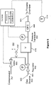
- Figure 6 shows an embodiment of the present invention that allows direct insertion into existing semiconductor and related gas delivery systems.
- This embodiment takes advantage of the fact that many regulators in current use have a rarely exploited configuration that allows an increase in set point to take place by increasing the pressure above the pressure regulator's diaphragm. Normally, the volume above the diaphragm is exposed to atmosphere; however, by increasing the pressure in this volume to a level above atmospheric pressure, the regulated pressure also rises.
- this increase in pressure is achieved by the addition of valve 606, that may be controlled to deliver a prescribed amount of compressed air or other compressed gas, such as nitrogen, to the top-side of the regulator 602, hereby controlling the set point of regulator 602. Since the compressed air is delivered to the top-side of regulator 602, the air does not mix with the gas delivered to the process chamber.
- the embodiments in Figure 2 and 4 use a fixed volume defined by the closure of a valve (206 or 406)
- the embodiment in Figure 6 does not use a valve. Rather, the embodiment of Figure 6 uses the flow vs. pressure relationship of the pressure regulator to create the conditions required for the present invention. Significantly, these conditions exist only while the pressure downstream of the pressure regulator is larger than the pressure that under normal circumstances would be established by the regulator.
- the important property of the regulator is that, during the measurement of the flow of gas through the GFC, there is no flow of gas in either direction through the regulator. According to the behavior of a pressure regulator, as long as the pressure of the gas downstream of the regulator is no lower than the pressure to which it is set, it will not allow any flow of gas to the downstream side of the regulator. In addition, even if the pressure of the gas downstream of the regulator is higher than the pressure that it is set to establish, there is no capability of the regulator that would allow it to flow gas from the downstream side to the upstream side. Since there is no gas flowing in either direction through the regulator under these conditions, it satisfies the conditions required for measurement of the gas flow through the GFC according to the present invention.
- a key advantage of this embodiment is that only pressure regulator 602, volume 610, pressure transducer 612, and GFC 608 are part of the high purity gas delivery system. Significantly, these are the same conventional components shown in Figure 5 .
- the valve 606 is outside the high purity gas delivery system, and is similar to the valves that supply the compressed air or other gas for actuation of various pneumatic valves in the fabrication system. As such, it is easily added to the gas delivery system. It should also be noted that if for any reason the actual pressure regulator or pressure transducer required for the present invention is different from that already existing in the system, these components can be easily changed out. In addition, if the volume of the existing system is not as large as desired, a specially fabricated volume that also includes a pressure transducer could be inserted in place of the currently existing pressure transducer.
- the procedure for testing the flow of gas through the GFC may be summarized in the process flow 650 of FIG. 6A as follows.
- the flow rate of the GFC for this embodiment is calculated in a manner identical to that of the embodiment of Figure 2 , and is consequently given by Equation (4).
- the GFC be set to the desired flow rate prior to opening and closing the valve 606.
- the GFC could be set to the desired flow rate after the valve 606 is opened, but before it is closed, or it could be set to the desired flow rate after the valve has been both opened and closed.
- Figure 6 shows one specific embodiment for controlling the rise in pressure as effected by the pressure regulator, any approach that will momentarily increase the pressure downstream of the pressure regulator will be adequate. What is required is that the measurement is taken place after the pressure in the volume upstream of the GFC has been increased to above the normal set point, so that as gas is delivered to the chamber the pressure is reduced towards the normal pressure so that perturbations on the GFC are avoided. Also, while the normal set point is assumed to be that produced by atmospheric pressure above the diaphragm, this is not necessary. What is required is that the opening of valve 606 would raise the set point of regulator 602 to a pressure higher than its normal set point.
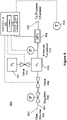
- Figure 7 is a simplified schematic diagram of an alternative embodiment to that in Figure 6 .
- the embodiment of Figure 7 utilizes the standard regulator 702, volume 710, transducer 712 and GFC 708, but adds a bypass valve 706 in parallel with the pressure regulator 702.
- Bypass valve 706 enables increasing the pressure downstream of regulator 702, beyond the set point of the regulator 702. This creates a similar effect as that of the embodiment of Figure 6 .
- the additional bypass valve 706 is part of the high purity gas delivery system and needs to comply with cleanliness standards of the system.
- FIG. 7A illustrates the process in its general form.
- step 752 the flow of the GFC is established while the regulator is set to its standard set point.
- step 754 the pressure downstream of the regulator is increased. Note that the order of steps 752 and 754 can be reversed.
- step 758 while processing in the chamber proceeds, the pressure downstream of the regulator is measured at intervals. Also, at step 760, which can be done at any time, the temperature is measured. The flow is calculated using the pressure measurements taken in step 758.
- One of the simplest ways to use the embodiment of Figure 6 or 7 is to use the compressed air (or any other compressed gas, such as nitrogen) of Figure 6 or the bypass flow of process gas through Valve 706 of Figure 7 to increase the pressure downstream of the pressure regulator to a certain value and then during the operation of the GFC, allow the pressure to decrease to the normal set point of the regulator.
- the pressure will still be decreasing after the flow rate measurement has been made.
- this pressure could be controlled in such a way that as soon as the flow measurement is made, the pressure is held constant for the remainder of the process step.
- a relative change in flow rate may be determined based upon a comparison of different pressure drop measurements.
- two sets of pressure drop measurements may be taken to provide a relative measure of changed flow rate.
- the first measurement may be taken from the GFC that is to be tested, with the second measurement taken from a GFC of known performance. A difference between the two pressure drop readings could reveal deviation of flow rate by the tested device, without determination of the actual flow rate.
- a first pressure drop measurement may be taken at a first time with the GFC that is to be tested, with the second pressure drop measurement being taken from that same GFC at a second time.
- a difference between the two pressure drop measurements readings could reveal the magnitude of change (drift) in the flow rate from the tested device, over time.
- the present invention can be performed with automatic operation and since the measurements are being carried out in real time as the gas is being flowed into the process chamber, the present invention makes it possible to correct any deviation in the actual flow of gas while the process is being carried out. If, for example, the gas flow controller is set to 100 standard cubic centimeters per minute (sccm) of gas mass flow, and if the measured result is 98 sccm, the set point could be increased to 102 sccm, thus bringing the actual flow to the desired 100 sccm.
- sccm standard cubic centimeters per minute
- Figure 8 shows an embodiment in which the gas flow controller under test is replaced by a control valve.
- the present invention is used to directly control the output control valve to provide the desired flow.
- the controller notes a difference between the measured flow rate and the desired set point, and it changes the valve opening to minimize this difference.
- the actual flow rate is very close to the desired flow rate.
- the present invention allows the capability for the controller that is taking the measurements and controlling the control valve 808 to have information, a priori, on the required valve position for a desired flow rate.
- a separate measurement technique such as a rate of rise volume positioned downstream of the control valve 808, to note the valve position for a given flow rate at a certain pressure and temperature, where the pressure was set and held constant by the pressure regulator. Since this initial calibration would only be done once, it would not be a large inconvenience to use a separate technique for measuring the flow.
- step 866 rather than waiting for the pressure to drop to the set point of the regulator 802, one could control the effective set point, in a manner as described with respect to Figure 6 , such that soon after the flow rate was measured, the pressure was brought to a steady value.
- the metering valve of Figure 4 or the shut off valve and restrictor of Figure 4A could be substituted for the regulator 802 and valve 806 of Figure 8 .
- the shut off valve and restrictor of Figure 4A could be used to bring the pressure to the starting point, or the metering valve of Figure 4 could be used to either hold the pressure constant or to slowly raise it.
- Figure 9 illustrates another embodiment according to the invention, which allows determination of volume without having to change out any of the existing components. While this feature is illustrated with respect to an arrangement mimicking that of Figure 2 , it should be readily appreciated that this feature may be implemented using any of the embodiments discussed above.
- the volume V is equal to V 1 + V 2 , where V 2 is the volume of chamber 911 having a known volume, and V 1 is the fixed volume (represented by box 910) of all other components in the gas delivery system between the GFC 908 and Valve 906.
- the known volume V 2 is the volume of the chamber 911 when the Valve 912 is closed.
- This known volume V 2 can be determined prior to incorporation of chamber 911 into the gas delivery system, in any one of a number of ways.
- One direct method is to (1) fill the chamber with a liquid to a point beyond the valve 912, (2) close the valve 912, (3) pour off any liquid that is outside of the valve 912, and then (4) open the valve 912 and pour out the liquid into a measurement vessel such as a beaker or burette.
- the measurement of V may proceed. Specifically, evacuation of the fixed volume 910 by flow through the gas flow controller 908, followed by opening the second valve 912 to unite the fixed volume 910 with the chamber 911, can produce a pressure drop that allows accurate calculation of the fixed volume 910.
- Figure 9A provides a simplified diagram of the flow 950 of steps of this approach, which may be executed by computer 920.
- Equation (5) The reason that V 2 is present in Equation (5) instead of V, is because in step 964 everything in the system except chamber 911 of volume V 2 was emptied of any gas.
- V 1 V ⁇ V 2 .
- V and V 1 in this manner does require a separate step during which no productive use can be made of the processing chamber. However, this volume measurement would be expected to be carried out only relatively infrequently. Whereas the measurement of gas flow rate described above in connection with the other embodiments might be conducted on a daily basis or even more frequently, measurement of the volumes V and V 1 as described in connection with Figures 9-9A would be done upon first installation of the apparatus, and then perhaps only when a component of the system is changed.
- valve 912 could be closed such that only volume V 1 is used in lieu of V for the gas flow measurement.
- the flow rate is large relative to the fixed volume V 1 , it may be appropriate to leave the second valve open to provide a larger combined volume (V 1 + V 2 ) and thereby provide sufficient time for the pressure drop to take place.
- the host computer may control valve 912 to match the volume to the gas flow.
- the host computer closes valve 912, so that only volume V 1 is utilized. Conversely, when the gas flow is increased, the host computer would open valve 912, so that volume V is utilized.
- Figure 9B illustrates a variation on the idea of variable volume, according to an embodiment of the invention.
- system 900B includes two additional volumes 911 and 931, which may be opened or closed to the system using valves 912 and 932.
- Volumes 911 and 931 may be of same or different value.
- the utilized volume may be V 1 , V 1 + V 2 , V 1 + V 3 , or V 1 + V 2 + V 3 .
- additional volumes with corresponding valves may be added if needed.
- FIG 9C illustrates a conceptual generalization on the idea of variable volume, according to an embodiment of the invention.
- the volume V 1 is made variable, as conceptually illustrated by the membrane 911 and the double-headed arrow.
- the volume can be varied manually or using host computer, as illustrated by the broken line.
- the size of volume V 1' may be set once for all processes, or may be changed during the process if the flow rate is changed during processing.
- FIG. 9 Yet another method can be used with the embodiment of Figure 9 to determine the unknown volume V 1 .
- the GFC is set to a flow rate that allows an accurate measurement of ( ⁇ P/ ⁇ t) while utilizing either volume V 1 alone or V 1 + V 2 .
- Valve 912 For the initial part of the measurement, Valve 912 is open. A measurement, ( ⁇ P/ ⁇ t)', is made under these conditions. While the GFC is still flowing, Valve 912 is closed. Another measurement, ( ⁇ P/ ⁇ t)", is made. As shown in the equations below, the ratio of these two values of ( ⁇ P/ ⁇ t) allows a determination of the unknown volume.
- One or more steps of the various embodiments of the present invention could be performed with manual or automatic operation.
- the steps of opening/closing valves and taking pressure readings could be conducted automatically according to computer control, with the actual determination of the volume taking place manually or automatically.
- one or more of the various valves could be actuated manually, with the resulting flow rate calculated automatically from the detected pressure drop.
- Automatic operation of one or more steps could be accomplished based upon instructions stored in a computer readable storage medium of a host computer comprising a processor, utilizing communication through control lines as indicated by dashed-lines in the Figures.
- Embodiments of the present invention may offer a number of advantages over conventional approaches.
- One advantage is that the testing of flow rate may be performed while the mass flow controller is going about its normal operation. Specifically, because the pressure variations caused by the opening and closing of the valves are controlled to prevent disturbance of the GFC, the GFC is able to maintain its specified flow rate despite the intentionally introduced changes in inlet pressure.
- Gas flow testing can take place while the gas flow controller is operating normally to deliver gas to a processing chamber during production.
- the testing apparatus is an integral part of the gas delivery system, and all steps of the gas flow testing can be automated. Accordingly, embodiments of the present invention lend themselves to fully automated operation, including the initiation of the testing procedure.
- the flow rate test can be programmed to occur at every process step, or at a particular event, such as during a particular step of a particular process when the gas flow controller is set to a particular flow rate.
- the test can be programmed to take place at a certain time or times each day.
- Embodiments of the present invention can also provide an alarm, which could include an audible or visual alarm located on the process tool.
- an alarm in the form of an e-mail can be sent to one or more designated persons, if the measured flow rate is outside of certain limits. Such an approach works well in conjunction with the fully automated initiation and operation described above.
- Embodiments of the present invention can also be used to measure the transient response of the MFC.
- an MFC When an MFC is perturbed, for example by turning it on or changing its set point or by suddenly increasing the pressure upstream of the MFC, it will take a few seconds to attain its steady state flow. During those few seconds, the flow rate of the MFC will deviate from the set point, often oscillating above and below the set point.
- the manner in which it deviates can be measured by the present invention by taking multiple pressure readings at a relatively high sampling rate (e.g., 10 to 100 readings per second) immediately after the MFC is perturbed. This measurement of the transient response has several advantages.
- Embodiments in accordance with the present invention also allow for essentially an unchanging environment to be presented to the gas being measured. Such unchanging conditions essentially prevent any errors associated with reactions with deposits or adsorbed gases inside the system, from disturbing the outcome.
- Embodiments of the present invention also allow for a rapid determination of the system volume, measured by the system itself, if anything associated with the system is changed. This obviates the need for manually-intensive time-consuming measurements, such as those that would be needed to determine the volume of the process chamber.
Claims (9)
- Verfahren zur Bestimmung eines Gasdurchsatzes über einen Gasdurchflussregler (GFC) in eine Prozesskammer, wobei das Verfahren folgende Schritte umfasst:Aufbauen eines Gasflusses durch den Gasdurchflussregler (GFC) mit konstanter Geschwindigkeit;Festlegen eines bekannten Volumens in Strömungsrichtung vor dem Gasdurchflussregler (GFC) durch Unterbrechen des Gasflusses in Strömungsrichtung vor dem bekannten Volumen;Durchführen eines Prozesses in der Prozesskammer, und während des Prozesses:Messen eines ersten Drucks in dem Volumen zu einem ersten Zeitpunkt;Messen eines zweiten Drucks in dem Volumen zu einem zweiten Zeitpunkt nach dem ersten Zeitpunkt;Bestimmen einer Druckabfallrate anhand des ersten und des zweiten Drucks;Bestimmen des festgelegten Durchsatzes auf der Grundlage der Druckabfallrate und des bekannten Volumens; undWiederherstellen des Gasflusses in das Volumen derart, dass keine Störung des Durchflusses durch den Gasdurchflussregler (GFC) über ein bestimmtes Maß hinaus verursacht wird,dadurch gekennzeichnet, dass das Wiederherstellen des Gasflusses in das bekannte Volumen mit geregelter Durchflussmenge erfolgt, sodass die Druckanstiegsrate innerhalb des bekannten Volumens gering genug ist, um keine Störung des Gasdurchflussreglers (GFC) über 1 % hinaus zu verursachen.
- Verfahren nach Anspruch 1, bei dem die Einstellung der geregelten Durchflussmenge mit einem Dosierventil (406) erfolgt.
- Verfahren nach Anspruch 1, bei dem die Einstellung der geregelten Durchflussmenge mittels eines Durchflussbegrenzers (422) in Reihe mit einem Sperrventil (406') erfolgt.
- Verfahren nach Anspruch 1, bei dem das bekannte Volumen durch Schließen eines in Strömungsrichtung vor dem Gasdurchflussregler (GFC) angeordneten Ventils (406) festgelegt wird.
- Verfahren nach Anspruch 1, bei dem ein Druckregler (202) in Strömungsrichtung vor dem Gasdurchflussregler (GFC) vorgesehen ist, sodass sich das bekannte Volumen zwischen dem Druckregler (202) und dem Gasflussdurchflussregler (GFC) befindet, und wobei das Festlegen eines bekannten Volumens in Strömungsrichtung vor dem Gasdurchflussregler (GFC) durch Unterbrechen des Gasflusses in Strömungsrichtung vor dem bekannten Volumen das Erhöhen des Sollwerts des Druckreglers (202) zur Steigerung des Drucks in dem bekannten Volumen und im Anschluss daran - vor der Messung zu einem ersten Zeitpunkt - das Zurücksetzen des Druckreglers (202) auf den normalen Sollwert umfasst.
- Vorrichtung zur Bestimmung eines Gasdurchsatzes über einen Gasdurchflussregler (GFC), wobei die Vorrichtung Folgendes umfasst:Mittel zum Festlegen eines bekannten Volumens in Strömungsrichtung vor dem Gasdurchflussregler (GFC) durch Unterbrechen des Gasflusses in Strömungsrichtung vor dem bekannten Volumen;Mittel zum Messen des Druckabfalls in dem festgelegten Volumen;gekennzeichnet durch Mittel zum Wiederherstellen des Gasflusses in das bekannte Volumen derart, dass keine Störung des Gasdurchsatzes durch den Gasdurchflussregler (GFC) über 1 % hinaus verursacht wird.
- Vorrichtung nach Anspruch 6, bei der das Mittel zum Festlegen eines bekannten Volumens in Strömungsrichtung vor dem Gasdurchflussregler (GFC) einen Druckregler (202) umfasst.
- Vorrichtung nach Anspruch 6, bei der das Mittel zum Festlegen eines bekannten Volumens in Strömungsrichtung vor dem Gasdurchflussregler (GFC) ein Dosierventil (406) umfasst.
- Vorrichtung nach Anspruch 6, bei der das Mittel zum Festlegen eines bekannten Volumens in Strömungsrichtung vor dem Gasdurchflussregler (GFC) ein Sperrventil (406') in Reihe mit einem Durchflussbegrenzer (422) umfasst.
Applications Claiming Priority (4)
| Application Number | Priority Date | Filing Date | Title |
|---|---|---|---|
| US2202608P | 2008-01-18 | 2008-01-18 | |
| US8019608P | 2008-07-11 | 2008-07-11 | |
| US9014708P | 2008-08-19 | 2008-08-19 | |
| PCT/US2009/031170 WO2009091935A1 (en) | 2008-01-18 | 2009-01-15 | Method and apparatus for in situ testing of gas flow controllers |
Publications (3)
| Publication Number | Publication Date |
|---|---|
| EP2247819A1 EP2247819A1 (de) | 2010-11-10 |
| EP2247819A4 EP2247819A4 (de) | 2018-02-07 |
| EP2247819B1 true EP2247819B1 (de) | 2022-11-02 |
Family
ID=40875370
Family Applications (1)
| Application Number | Title | Priority Date | Filing Date |
|---|---|---|---|
| EP09702610.8A Active EP2247819B1 (de) | 2008-01-18 | 2009-01-15 | Verfahren und vorrichtung für die vorortprüfung von gasströmungssteuerungen |
Country Status (7)
| Country | Link |
|---|---|
| US (4) | US7823436B2 (de) |
| EP (1) | EP2247819B1 (de) |
| JP (3) | JP2011510404A (de) |
| KR (1) | KR101840047B1 (de) |
| CN (1) | CN101978132B (de) |
| TW (1) | TWI399627B (de) |
| WO (1) | WO2009091935A1 (de) |
Families Citing this family (82)
| Publication number | Priority date | Publication date | Assignee | Title |
|---|---|---|---|---|
| US7822570B2 (en) * | 2006-11-17 | 2010-10-26 | Lam Research Corporation | Methods for performing actual flow verification |
| TWI444799B (zh) * | 2006-12-05 | 2014-07-11 | Horiba Stec Co | 流量控制裝置與流量測定裝置之校準方法、流量控制裝置之校準系統、及半導體製造裝置 |
| JP5054500B2 (ja) * | 2007-12-11 | 2012-10-24 | 株式会社フジキン | 圧力制御式流量基準器 |
| KR101840047B1 (ko) * | 2008-01-18 | 2018-03-19 | 피포탈 시스템즈 코포레이션 | 가스 유동 제어기의 인 시투 시험을 위한 방법 및 장치 |
| US7891228B2 (en) * | 2008-11-18 | 2011-02-22 | Mks Instruments, Inc. | Dual-mode mass flow verification and mass flow delivery system and method |
| TWI435196B (zh) | 2009-10-15 | 2014-04-21 | Pivotal Systems Corp | 氣體流量控制方法及裝置 |
| US8271211B2 (en) * | 2009-12-09 | 2012-09-18 | Pivotal Systems Corporation | Method and apparatus for enhancing in-situ gas flow measurement performance |
| US8271210B2 (en) * | 2009-12-09 | 2012-09-18 | Pivotal Systems Corporation | Method and apparatus for enhancing in-situ gas flow measurement performance |
| US8265888B2 (en) * | 2009-12-09 | 2012-09-11 | Pivotal Systems Corporation | Method and apparatus for enhancing in-situ gas flow measurement performance |
| JP4815538B2 (ja) | 2010-01-15 | 2011-11-16 | シーケーディ株式会社 | 真空制御システムおよび真空制御方法 |
| EP2366448B1 (de) | 2010-03-16 | 2016-07-27 | Amminex Emissions Technology A/S | Verfahren und Vorrichtung zur kontrollierten Dosierung eines Gases mit veränderlichem Zuströmdruck |
| TWI418751B (zh) * | 2010-04-27 | 2013-12-11 | Delta Electronics Inc | 可量測流量之氣流驅動裝置及其適用之空調設備 |
| JP5538119B2 (ja) * | 2010-07-30 | 2014-07-02 | 株式会社フジキン | ガス供給装置用流量制御器の校正方法及び流量計測方法 |
| KR101208960B1 (ko) * | 2010-11-26 | 2012-12-06 | 에스케이하이닉스 주식회사 | 반도체 장치 및 이의 테스트 방법 |
| US9400004B2 (en) | 2010-11-29 | 2016-07-26 | Pivotal Systems Corporation | Transient measurements of mass flow controllers |
| JP6355336B2 (ja) * | 2010-11-30 | 2018-07-11 | インテグリス・インコーポレーテッド | 遠隔ドーパント源を含むイオン注入機システム及び当該イオン注入機システムを備える方法 |
| JP5528374B2 (ja) * | 2011-03-03 | 2014-06-25 | 東京エレクトロン株式会社 | ガス減圧供給装置、これを備えるシリンダキャビネット、バルブボックス、及び基板処理装置 |
| JP5430621B2 (ja) * | 2011-08-10 | 2014-03-05 | Ckd株式会社 | ガス流量検定システム及びガス流量検定ユニット |
| JP5433660B2 (ja) * | 2011-10-12 | 2014-03-05 | Ckd株式会社 | ガス流量監視システム |
| JP5809012B2 (ja) * | 2011-10-14 | 2015-11-10 | 株式会社堀場エステック | 流量制御装置、流量測定機構、又は、当該流量測定機構を備えた流量制御装置に用いられる診断装置及び診断用プログラム |
| EP2618143B1 (de) | 2012-01-19 | 2015-05-27 | Idexx Laboratories, Inc. | Analysator mit Vorrichtung zur Steuerung des Flüssigkeitsdrucks |
| US9557744B2 (en) | 2012-01-20 | 2017-01-31 | Mks Instruments, Inc. | System for and method of monitoring flow through mass flow controllers in real time |
| US9846074B2 (en) | 2012-01-20 | 2017-12-19 | Mks Instruments, Inc. | System for and method of monitoring flow through mass flow controllers in real time |
| US9471066B2 (en) | 2012-01-20 | 2016-10-18 | Mks Instruments, Inc. | System for and method of providing pressure insensitive self verifying mass flow controller |
| JP6224630B2 (ja) | 2012-03-07 | 2017-11-01 | イリノイ トゥール ワークス インコーポレイティド | 質量流量制御器または質量流量計のゼロオフセットおよびゼロドリフトのリアルタイム測定および補正に減衰速度測定を用いるためのシステムおよび方法 |
| WO2013134140A1 (en) * | 2012-03-07 | 2013-09-12 | Illinois Tool Works Inc. | System and method for reducing flow perturbations and improving the accuracy of a rate of decay measurement in a mass flow controller |
| US9810377B2 (en) | 2012-03-07 | 2017-11-07 | Illinois Tool Works Inc. | System and method for improving the accuracy of a rate of decay (ROD) measurement in a mass flow controller |
| JP6426475B2 (ja) | 2012-03-07 | 2018-11-21 | イリノイ トゥール ワークス インコーポレイティド | 熱モデルを用いてrod測定における熱に起因する誤差を最小にすることによって質量流量制御器または質量流量計における実時間補正のための減衰速度測定の精度を改善するためのシステムおよび方法 |
| WO2013134147A1 (en) * | 2012-03-07 | 2013-09-12 | Illinois Tool Works Inc. | System and method for providing a self validating mass flow controller and mass flow meter |
| US9733649B2 (en) | 2012-05-31 | 2017-08-15 | Fujikin Incorporated | Flow control system with build-down system flow monitoring |
| FR2994455B1 (fr) * | 2012-08-10 | 2014-09-05 | Faurecia Sys Echappement | Ensemble de fourniture d'un flux dose de gaz, procede associe, ligne d'echappement de vehicule equipee d'un tel ensemble |
| US10031005B2 (en) * | 2012-09-25 | 2018-07-24 | Mks Instruments, Inc. | Method and apparatus for self verification of pressure-based mass flow controllers |
| US9127973B2 (en) * | 2013-01-31 | 2015-09-08 | GM Global Technology Operations LLC | Validation method for pressure sensor signal at electrical controlled high pressure gas storage systems |
| EP3036510B1 (de) | 2013-03-14 | 2021-06-09 | Christopher Max Horwitz | Druckbasierte gasströmungssteuerung mit dynamischer selbstkalibrierung |
| US9454158B2 (en) | 2013-03-15 | 2016-09-27 | Bhushan Somani | Real time diagnostics for flow controller systems and methods |
| JP5847106B2 (ja) | 2013-03-25 | 2016-01-20 | 株式会社フジキン | 流量モニタ付圧力式流量制御装置。 |
| US9778083B2 (en) | 2013-05-16 | 2017-10-03 | Lam Research Corporation | Metrology method for transient gas flow |
| JP5797246B2 (ja) * | 2013-10-28 | 2015-10-21 | 株式会社フジキン | 流量計及びそれを備えた流量制御装置 |
| CN103791951B (zh) * | 2013-12-24 | 2016-09-28 | 兰州空间技术物理研究所 | 正压标准气体流量计及正压标准气体流量测量方法 |
| AT513535B1 (de) * | 2014-02-06 | 2015-09-15 | Avl List Gmbh | Verfahren zur Funktionsprüfung einer Anordnung zur dynamischen Kraftstoffverbrauchsmessung |
| US20150233745A1 (en) * | 2014-02-14 | 2015-08-20 | Rockwater Energy Solutions | Method and Apparatus for Metering in Liquid Distribution System |
| US9605346B2 (en) * | 2014-03-28 | 2017-03-28 | Lam Research Corporation | Systems and methods for pressure-based liquid flow control |
| CN104142377B (zh) * | 2014-07-17 | 2016-03-23 | 上海冷杉精密仪器有限公司 | 一种低成本的气相色谱仪的气路系统 |
| US10094018B2 (en) | 2014-10-16 | 2018-10-09 | Lam Research Corporation | Dynamic precursor dosing for atomic layer deposition |
| US11970772B2 (en) | 2014-08-22 | 2024-04-30 | Lam Research Corporation | Dynamic precursor dosing for atomic layer deposition |
| US11072860B2 (en) | 2014-08-22 | 2021-07-27 | Lam Research Corporation | Fill on demand ampoule refill |
| DE102015100762A1 (de) * | 2015-01-20 | 2016-07-21 | Infineon Technologies Ag | Behälterschalteinrichtung und Verfahren zum Überwachen einer Fluidrate |
| EP3320408A1 (de) * | 2015-07-10 | 2018-05-16 | Pivotal Systems Corporation | Verfahren und vorrichtung für gasflusssteuerung |
| US10957561B2 (en) * | 2015-07-30 | 2021-03-23 | Lam Research Corporation | Gas delivery system |
| EP3347634B1 (de) * | 2015-09-10 | 2021-08-25 | Festo SE & Co. KG | Fluidsystem und prozessventil |
| US10192751B2 (en) | 2015-10-15 | 2019-01-29 | Lam Research Corporation | Systems and methods for ultrahigh selective nitride etch |
| US10126761B2 (en) | 2015-12-29 | 2018-11-13 | Hitachi Metals, Ltd. | Gas insensitive mass flow control systems and methods |
| US10825659B2 (en) | 2016-01-07 | 2020-11-03 | Lam Research Corporation | Substrate processing chamber including multiple gas injection points and dual injector |
| US10147588B2 (en) | 2016-02-12 | 2018-12-04 | Lam Research Corporation | System and method for increasing electron density levels in a plasma of a substrate processing system |
| US10699878B2 (en) | 2016-02-12 | 2020-06-30 | Lam Research Corporation | Chamber member of a plasma source and pedestal with radially outward positioned lift pins for translation of a substrate c-ring |
| US10651015B2 (en) | 2016-02-12 | 2020-05-12 | Lam Research Corporation | Variable depth edge ring for etch uniformity control |
| US10438833B2 (en) | 2016-02-16 | 2019-10-08 | Lam Research Corporation | Wafer lift ring system for wafer transfer |
| US10684159B2 (en) * | 2016-06-27 | 2020-06-16 | Applied Materials, Inc. | Methods, systems, and apparatus for mass flow verification based on choked flow |
| US10410832B2 (en) | 2016-08-19 | 2019-09-10 | Lam Research Corporation | Control of on-wafer CD uniformity with movable edge ring and gas injection adjustment |
| US10697848B1 (en) * | 2016-12-12 | 2020-06-30 | Kirk A. Dobbs | Smart building water supply management system with leak detection and flood prevention |
| JP6775403B2 (ja) * | 2016-12-14 | 2020-10-28 | 株式会社堀場エステック | 流体特性測定システム |
| US10983537B2 (en) | 2017-02-27 | 2021-04-20 | Flow Devices And Systems Inc. | Systems and methods for flow sensor back pressure adjustment for mass flow controller |
| TWI607842B (zh) * | 2017-05-04 | 2017-12-11 | Gison Machinery Co Ltd | Low pressure warning device, low pressure warning device and low pressure warning method for pneumatic tools |
| KR20200054994A (ko) * | 2017-09-29 | 2020-05-20 | 히타치 긴조쿠 가부시키가이샤 | 질량 유량 제어 시스템 및 당해 시스템을 포함하는 반도체 제조 장치 및 기화기 |
| CN109633206B (zh) * | 2017-10-09 | 2021-03-02 | 中核兰州铀浓缩有限公司 | 六氟化铀气体流向保护传感器的模拟测试系统及方法 |
| US20200319658A1 (en) * | 2017-10-25 | 2020-10-08 | Flow Devices And Systems Inc. | Wide range. low flow rate of decay, temperature determination flow controller |
| KR102101068B1 (ko) | 2017-12-11 | 2020-04-14 | 조북룡 | 통합 분석기에 의한 질량 유량 최적화 제어 시스템 |
| CN111372887B (zh) * | 2017-12-21 | 2022-08-23 | 西得乐公司 | 控制调节填充阀的方法以及用于执行该方法的填充装置 |
| US20190226896A1 (en) * | 2018-01-22 | 2019-07-25 | Feng Zhang | Novel Electronic Gas Meter |
| US10866135B2 (en) * | 2018-03-26 | 2020-12-15 | Applied Materials, Inc. | Methods, systems, and apparatus for mass flow verification based on rate of pressure decay |
| JP7157476B2 (ja) * | 2018-04-27 | 2022-10-20 | 株式会社フジキン | 流量制御方法および流量制御装置 |
| US11327510B2 (en) * | 2018-05-23 | 2022-05-10 | Hitachi Metals, Ltd. | Multi-chamber rate-of-change system for gas flow verification |
| WO2019240075A1 (ja) * | 2018-06-15 | 2019-12-19 | 株式会社堀場エステック | 配管容積の算出方法、及び、流量制御機器又は流量計測機器の校正器 |
| US11216016B2 (en) | 2018-06-26 | 2022-01-04 | Fujikin Incorporated | Flow rate control method and flow rate control device |
| US11004711B2 (en) * | 2018-08-17 | 2021-05-11 | Taiwan Semiconductor Manufacturing Co., Ltd. | Automated wafer monitoring |
| JP2020139864A (ja) * | 2019-02-28 | 2020-09-03 | 株式会社堀場エステック | 流量算出システム、流量算出システム用プログラム、流量算出方法、及び、流量算出装置 |
| CN110260931B (zh) * | 2019-06-18 | 2020-12-11 | 西安航天动力试验技术研究所 | 一种液体推进剂管道流场品质评价系统及评价方法 |
| EP3848579B1 (de) * | 2020-01-13 | 2023-08-02 | Promix Solutions AG | System und verfahren zur dosierung eines flüssigen oder gasförmigen mediums |
| WO2022004349A1 (ja) * | 2020-06-29 | 2022-01-06 | 株式会社フジキン | 流体制御装置、流体供給システムおよび流体供給方法 |
| CN112540629A (zh) * | 2020-11-18 | 2021-03-23 | 河南卓正电子科技有限公司 | 一种智能阀门流量标定方法及装置 |
| US11815388B2 (en) * | 2020-12-01 | 2023-11-14 | Honeywell International Inc. | Method and system for timely detecting gas pressure irregularities using a gas meter in a power efficient manner |
| US11733081B2 (en) | 2021-04-13 | 2023-08-22 | Applied Materials, Inc. | Methods, systems, and apparatus for conducting a calibration operation for a plurality of mass flow controllers (MFCs) of a substrate processing system |
Family Cites Families (31)
| Publication number | Priority date | Publication date | Assignee | Title |
|---|---|---|---|---|
| US4285245A (en) * | 1979-12-06 | 1981-08-25 | Precision Machine Products, Inc. | Method and apparatus for measuring and controlling volumetric flow rate of gases in a line |
| JPS6062118U (ja) | 1983-10-04 | 1985-05-01 | 株式会社 京浜精機製作所 | 流量制御弁 |
| JPS62141381A (ja) | 1985-12-16 | 1987-06-24 | Hitachi Metals Ltd | 圧電駆動式弁 |
| JPH0694909B2 (ja) | 1988-12-15 | 1994-11-24 | 工業技術院長 | 圧電素子を用いた流体制御バルブ |
| US5062446A (en) * | 1991-01-07 | 1991-11-05 | Sematech, Inc. | Intelligent mass flow controller |
| AU1678595A (en) * | 1994-01-14 | 1995-08-01 | Unit Instruments, Inc. | Flow meter |
| US5684245A (en) * | 1995-11-17 | 1997-11-04 | Mks Instruments, Inc. | Apparatus for mass flow measurement of a gas |
| US5868159A (en) * | 1996-07-12 | 1999-02-09 | Mks Instruments, Inc. | Pressure-based mass flow controller |
| US5865417A (en) | 1996-09-27 | 1999-02-02 | Redwood Microsystems, Inc. | Integrated electrically operable normally closed valve |
| DE19735156C1 (de) | 1996-11-25 | 1999-04-29 | Fraunhofer Ges Forschung | Piezoelektrisch betätigtes Mikroventil |
| US6363958B1 (en) * | 1999-05-10 | 2002-04-02 | Parker-Hannifin Corporation | Flow control of process gas in semiconductor manufacturing |
| US6119710A (en) * | 1999-05-26 | 2000-09-19 | Cyber Instrument Technologies Llc | Method for wide range gas flow system with real time flow measurement and correction |
| US6138708A (en) * | 1999-07-28 | 2000-10-31 | Controls Corporation Of America | Mass flow controller having automatic pressure compensator |
| JP2002099330A (ja) | 2000-09-22 | 2002-04-05 | Aera Japan Ltd | 流量制御装置 |
| US6782906B2 (en) * | 2000-12-28 | 2004-08-31 | Young-Chul Chang | Time based mass flow controller and method for controlling flow rate using it |
| JP2002200597A (ja) | 2000-12-28 | 2002-07-16 | Matsushita Electric Works Ltd | 半導体マイクロアクチュエータ及びこれを用いた半導体マイクロバルブ |
| JP3801446B2 (ja) * | 2001-01-15 | 2006-07-26 | 大日本スクリーン製造株式会社 | 基板処理装置 |
| JP3756429B2 (ja) | 2001-07-12 | 2006-03-15 | Smc株式会社 | 流量制御弁 |
| US6981518B2 (en) | 2002-03-15 | 2006-01-03 | Cytonome, Inc. | Latching micro-regulator |
| US7809473B2 (en) * | 2002-06-24 | 2010-10-05 | Mks Instruments, Inc. | Apparatus and method for pressure fluctuation insensitive mass flow control |
| US7136767B2 (en) * | 2002-06-24 | 2006-11-14 | Mks Instruments, Inc. | Apparatus and method for calibration of mass flow controller |
| US6948508B2 (en) | 2002-06-24 | 2005-09-27 | Mks Instruments, Inc. | Apparatus and method for self-calibration of mass flow controller |
| ES2242141T3 (es) * | 2003-02-10 | 2005-11-01 | Korsch Ag | Metodo y dispositivo para el control de una maquina rotativa para la fabricacion de tabletas. |
| JP4086057B2 (ja) * | 2004-06-21 | 2008-05-14 | 日立金属株式会社 | 質量流量制御装置及びこの検定方法 |
| CN100483286C (zh) * | 2004-06-21 | 2009-04-29 | 日立金属株式会社 | 流量控制装置及其调整方法 |
| JP2008089607A (ja) | 2004-06-21 | 2008-04-17 | Hitachi Metals Ltd | 質量流量制御装置及びこの調整方法 |
| WO2006014508A2 (en) * | 2004-07-07 | 2006-02-09 | Parker Hannifin Corporation | Flow control apparatus and method with internally isothermal control volume for flow verification |
| US7412986B2 (en) * | 2004-07-09 | 2008-08-19 | Celerity, Inc. | Method and system for flow measurement and validation of a mass flow controller |
| KR101840047B1 (ko) | 2008-01-18 | 2018-03-19 | 피포탈 시스템즈 코포레이션 | 가스 유동 제어기의 인 시투 시험을 위한 방법 및 장치 |
| US8205629B2 (en) * | 2008-04-25 | 2012-06-26 | Applied Materials, Inc. | Real time lead-line characterization for MFC flow verification |
| US8265888B2 (en) * | 2009-12-09 | 2012-09-11 | Pivotal Systems Corporation | Method and apparatus for enhancing in-situ gas flow measurement performance |
-
2009
- 2009-01-15 KR KR1020107018060A patent/KR101840047B1/ko active IP Right Grant
- 2009-01-15 US US12/354,723 patent/US7823436B2/en active Active
- 2009-01-15 WO PCT/US2009/031170 patent/WO2009091935A1/en active Application Filing
- 2009-01-15 JP JP2010543262A patent/JP2011510404A/ja active Pending
- 2009-01-15 CN CN200980109390.3A patent/CN101978132B/zh active Active
- 2009-01-15 EP EP09702610.8A patent/EP2247819B1/de active Active
- 2009-01-16 TW TW98101722A patent/TWI399627B/zh active
- 2009-01-16 US US12/355,654 patent/US8240324B2/en active Active
-
2010
- 2010-09-27 US US12/891,714 patent/US8667830B2/en active Active
-
2012
- 2012-08-13 US US13/584,736 patent/US8857456B2/en active Active
-
2013
- 2013-07-29 JP JP2013156603A patent/JP5654099B2/ja active Active
-
2014
- 2014-11-19 JP JP2014234087A patent/JP5971636B2/ja active Active
Also Published As
| Publication number | Publication date |
|---|---|
| US20120304781A1 (en) | 2012-12-06 |
| TWI399627B (zh) | 2013-06-21 |
| US8240324B2 (en) | 2012-08-14 |
| KR101840047B1 (ko) | 2018-03-19 |
| JP2015064893A (ja) | 2015-04-09 |
| EP2247819A4 (de) | 2018-02-07 |
| US20110011183A1 (en) | 2011-01-20 |
| JP5654099B2 (ja) | 2015-01-14 |
| KR20100114079A (ko) | 2010-10-22 |
| WO2009091935A1 (en) | 2009-07-23 |
| CN101978132B (zh) | 2015-04-29 |
| US20090183549A1 (en) | 2009-07-23 |
| US7823436B2 (en) | 2010-11-02 |
| EP2247819A1 (de) | 2010-11-10 |
| TW200938978A (en) | 2009-09-16 |
| JP2011510404A (ja) | 2011-03-31 |
| US20090183548A1 (en) | 2009-07-23 |
| JP5971636B2 (ja) | 2016-08-17 |
| US8667830B2 (en) | 2014-03-11 |
| JP2013239201A (ja) | 2013-11-28 |
| US8857456B2 (en) | 2014-10-14 |
| CN101978132A (zh) | 2011-02-16 |
Similar Documents
| Publication | Publication Date | Title |
|---|---|---|
| EP2247819B1 (de) | Verfahren und vorrichtung für die vorortprüfung von gasströmungssteuerungen | |
| US7412986B2 (en) | Method and system for flow measurement and validation of a mass flow controller | |
| US7461549B1 (en) | Mass flow verifiers capable of providing different volumes, and related methods | |
| US9400004B2 (en) | Transient measurements of mass flow controllers | |
| JP4788920B2 (ja) | 質量流量制御装置、その検定方法及び半導体製造装置 | |
| JP5538119B2 (ja) | ガス供給装置用流量制御器の校正方法及び流量計測方法 | |
| CN108885471B (zh) | 压力式流量控制装置和流量自诊断方法 | |
| US20140013838A1 (en) | Flow rate measurement device and flow rate measurement method for flow rate controller for gas supply device | |
| KR20140136022A (ko) | 유량 제어기 또는 유량 측정기의 실시간 측정과 제로 옵셋 또는 제로 드리프트 보정을 위한 감쇠율 측정을 사용하는 시스템과 방법 | |
| JP2009145986A (ja) | 圧力制御式流量基準器及びこれに用いる耐食性圧力式流量制御器 | |
| KR102420515B1 (ko) | 압력 감쇠 레이트에 기반한 질량 유동 검증을 위한 방법들, 시스템들, 및 장치 | |
| JP2008506116A (ja) | フロー測定およびマスフロー調整器の検証のための方法およびシステム | |
| JP7249030B2 (ja) | 流量測定装置内の容積測定方法および流量測定装置 | |
| CN117810130A (zh) | 测量气体流量的方法和校准流量控制器的方法 | |
| KR20070031445A (ko) | 유동 측정 그리고 질량 유동 제어기의 검증을 위한 방법 및시스템 |
Legal Events
| Date | Code | Title | Description |
|---|---|---|---|
| PUAI | Public reference made under article 153(3) epc to a published international application that has entered the european phase |
Free format text: ORIGINAL CODE: 0009012 |
|
| STAA | Information on the status of an ep patent application or granted ep patent |
Free format text: STATUS: REQUEST FOR EXAMINATION WAS MADE |
|
| 17P | Request for examination filed |
Effective date: 20100818 |
|
| AK | Designated contracting states |
Kind code of ref document: A1 Designated state(s): AT BE BG CH CY CZ DE DK EE ES FI FR GB GR HR HU IE IS IT LI LT LU LV MC MK MT NL NO PL PT RO SE SI SK TR |
|
| AX | Request for extension of the european patent |
Extension state: AL BA RS |
|
| DAX | Request for extension of the european patent (deleted) | ||
| RIN1 | Information on inventor provided before grant (corrected) |
Inventor name: CHALMERS, JAMES, MACALLEN Inventor name: DING, TAO Inventor name: MONKOWSKI, JOSEPH, R. Inventor name: CHEN, JIALING |
|
| RA4 | Supplementary search report drawn up and despatched (corrected) |
Effective date: 20180110 |
|
| RIC1 | Information provided on ipc code assigned before grant |
Ipc: E21B 33/128 20060101AFI20180104BHEP Ipc: E21B 43/12 20060101ALI20180104BHEP Ipc: G01F 25/00 20060101ALI20180104BHEP |
|
| STAA | Information on the status of an ep patent application or granted ep patent |
Free format text: STATUS: EXAMINATION IS IN PROGRESS |
|
| 17Q | First examination report despatched |
Effective date: 20210616 |
|
| STAA | Information on the status of an ep patent application or granted ep patent |
Free format text: STATUS: EXAMINATION IS IN PROGRESS |
|
| GRAP | Despatch of communication of intention to grant a patent |
Free format text: ORIGINAL CODE: EPIDOSNIGR1 |
|
| STAA | Information on the status of an ep patent application or granted ep patent |
Free format text: STATUS: GRANT OF PATENT IS INTENDED |
|
| INTG | Intention to grant announced |
Effective date: 20220629 |
|
| GRAS | Grant fee paid |
Free format text: ORIGINAL CODE: EPIDOSNIGR3 |
|
| GRAA | (expected) grant |
Free format text: ORIGINAL CODE: 0009210 |
|
| STAA | Information on the status of an ep patent application or granted ep patent |
Free format text: STATUS: THE PATENT HAS BEEN GRANTED |
|
| AK | Designated contracting states |
Kind code of ref document: B1 Designated state(s): AT BE BG CH CY CZ DE DK EE ES FI FR GB GR HR HU IE IS IT LI LT LU LV MC MK MT NL NO PL PT RO SE SI SK TR |
|
| REG | Reference to a national code |
Ref country code: GB Ref legal event code: FG4D |
|
| REG | Reference to a national code |
Ref country code: CH Ref legal event code: EP Ref country code: AT Ref legal event code: REF Ref document number: 1528892 Country of ref document: AT Kind code of ref document: T Effective date: 20221115 |
|
| REG | Reference to a national code |
Ref country code: DE Ref legal event code: R096 Ref document number: 602009064657 Country of ref document: DE |
|
| REG | Reference to a national code |
Ref country code: IE Ref legal event code: FG4D |
|
| REG | Reference to a national code |
Ref country code: NL Ref legal event code: FP |
|
| REG | Reference to a national code |
Ref country code: LT Ref legal event code: MG9D |
|
| REG | Reference to a national code |
Ref country code: AT Ref legal event code: MK05 Ref document number: 1528892 Country of ref document: AT Kind code of ref document: T Effective date: 20221102 |
|
| PG25 | Lapsed in a contracting state [announced via postgrant information from national office to epo] |
Ref country code: SE Free format text: LAPSE BECAUSE OF FAILURE TO SUBMIT A TRANSLATION OF THE DESCRIPTION OR TO PAY THE FEE WITHIN THE PRESCRIBED TIME-LIMIT Effective date: 20221102 Ref country code: PT Free format text: LAPSE BECAUSE OF FAILURE TO SUBMIT A TRANSLATION OF THE DESCRIPTION OR TO PAY THE FEE WITHIN THE PRESCRIBED TIME-LIMIT Effective date: 20230302 Ref country code: NO Free format text: LAPSE BECAUSE OF FAILURE TO SUBMIT A TRANSLATION OF THE DESCRIPTION OR TO PAY THE FEE WITHIN THE PRESCRIBED TIME-LIMIT Effective date: 20230202 Ref country code: LT Free format text: LAPSE BECAUSE OF FAILURE TO SUBMIT A TRANSLATION OF THE DESCRIPTION OR TO PAY THE FEE WITHIN THE PRESCRIBED TIME-LIMIT Effective date: 20221102 Ref country code: FI Free format text: LAPSE BECAUSE OF FAILURE TO SUBMIT A TRANSLATION OF THE DESCRIPTION OR TO PAY THE FEE WITHIN THE PRESCRIBED TIME-LIMIT Effective date: 20221102 Ref country code: ES Free format text: LAPSE BECAUSE OF FAILURE TO SUBMIT A TRANSLATION OF THE DESCRIPTION OR TO PAY THE FEE WITHIN THE PRESCRIBED TIME-LIMIT Effective date: 20221102 Ref country code: AT Free format text: LAPSE BECAUSE OF FAILURE TO SUBMIT A TRANSLATION OF THE DESCRIPTION OR TO PAY THE FEE WITHIN THE PRESCRIBED TIME-LIMIT Effective date: 20221102 |
|
| PG25 | Lapsed in a contracting state [announced via postgrant information from national office to epo] |
Ref country code: PL Free format text: LAPSE BECAUSE OF FAILURE TO SUBMIT A TRANSLATION OF THE DESCRIPTION OR TO PAY THE FEE WITHIN THE PRESCRIBED TIME-LIMIT Effective date: 20221102 Ref country code: LV Free format text: LAPSE BECAUSE OF FAILURE TO SUBMIT A TRANSLATION OF THE DESCRIPTION OR TO PAY THE FEE WITHIN THE PRESCRIBED TIME-LIMIT Effective date: 20221102 Ref country code: IS Free format text: LAPSE BECAUSE OF FAILURE TO SUBMIT A TRANSLATION OF THE DESCRIPTION OR TO PAY THE FEE WITHIN THE PRESCRIBED TIME-LIMIT Effective date: 20230302 Ref country code: HR Free format text: LAPSE BECAUSE OF FAILURE TO SUBMIT A TRANSLATION OF THE DESCRIPTION OR TO PAY THE FEE WITHIN THE PRESCRIBED TIME-LIMIT Effective date: 20221102 Ref country code: GR Free format text: LAPSE BECAUSE OF FAILURE TO SUBMIT A TRANSLATION OF THE DESCRIPTION OR TO PAY THE FEE WITHIN THE PRESCRIBED TIME-LIMIT Effective date: 20230203 |
|
| PG25 | Lapsed in a contracting state [announced via postgrant information from national office to epo] |
Ref country code: RO Free format text: LAPSE BECAUSE OF FAILURE TO SUBMIT A TRANSLATION OF THE DESCRIPTION OR TO PAY THE FEE WITHIN THE PRESCRIBED TIME-LIMIT Effective date: 20221102 Ref country code: EE Free format text: LAPSE BECAUSE OF FAILURE TO SUBMIT A TRANSLATION OF THE DESCRIPTION OR TO PAY THE FEE WITHIN THE PRESCRIBED TIME-LIMIT Effective date: 20221102 Ref country code: DK Free format text: LAPSE BECAUSE OF FAILURE TO SUBMIT A TRANSLATION OF THE DESCRIPTION OR TO PAY THE FEE WITHIN THE PRESCRIBED TIME-LIMIT Effective date: 20221102 Ref country code: CZ Free format text: LAPSE BECAUSE OF FAILURE TO SUBMIT A TRANSLATION OF THE DESCRIPTION OR TO PAY THE FEE WITHIN THE PRESCRIBED TIME-LIMIT Effective date: 20221102 |
|
| REG | Reference to a national code |
Ref country code: DE Ref legal event code: R097 Ref document number: 602009064657 Country of ref document: DE |
|
| PG25 | Lapsed in a contracting state [announced via postgrant information from national office to epo] |
Ref country code: SK Free format text: LAPSE BECAUSE OF FAILURE TO SUBMIT A TRANSLATION OF THE DESCRIPTION OR TO PAY THE FEE WITHIN THE PRESCRIBED TIME-LIMIT Effective date: 20221102 |
|
| REG | Reference to a national code |
Ref country code: CH Ref legal event code: PL |
|
| PLBE | No opposition filed within time limit |
Free format text: ORIGINAL CODE: 0009261 |
|
| STAA | Information on the status of an ep patent application or granted ep patent |
Free format text: STATUS: NO OPPOSITION FILED WITHIN TIME LIMIT |
|
| PG25 | Lapsed in a contracting state [announced via postgrant information from national office to epo] |
Ref country code: LU Free format text: LAPSE BECAUSE OF NON-PAYMENT OF DUE FEES Effective date: 20230115 |
|
| REG | Reference to a national code |
Ref country code: BE Ref legal event code: MM Effective date: 20230131 |
|
| 26N | No opposition filed |
Effective date: 20230803 |
|
| GBPC | Gb: european patent ceased through non-payment of renewal fee |
Effective date: 20230202 |
|
| PG25 | Lapsed in a contracting state [announced via postgrant information from national office to epo] |
Ref country code: LI Free format text: LAPSE BECAUSE OF NON-PAYMENT OF DUE FEES Effective date: 20230131 Ref country code: CH Free format text: LAPSE BECAUSE OF NON-PAYMENT OF DUE FEES Effective date: 20230131 |
|
| PG25 | Lapsed in a contracting state [announced via postgrant information from national office to epo] |
Ref country code: SI Free format text: LAPSE BECAUSE OF FAILURE TO SUBMIT A TRANSLATION OF THE DESCRIPTION OR TO PAY THE FEE WITHIN THE PRESCRIBED TIME-LIMIT Effective date: 20221102 Ref country code: FR Free format text: LAPSE BECAUSE OF NON-PAYMENT OF DUE FEES Effective date: 20230131 Ref country code: BE Free format text: LAPSE BECAUSE OF NON-PAYMENT OF DUE FEES Effective date: 20230131 |
|
| PGFP | Annual fee paid to national office [announced via postgrant information from national office to epo] |
Ref country code: DE Payment date: 20230721 Year of fee payment: 15 |
|
| PG25 | Lapsed in a contracting state [announced via postgrant information from national office to epo] |
Ref country code: GB Free format text: LAPSE BECAUSE OF NON-PAYMENT OF DUE FEES Effective date: 20230202 |
|
| PG25 | Lapsed in a contracting state [announced via postgrant information from national office to epo] |
Ref country code: IE Free format text: LAPSE BECAUSE OF NON-PAYMENT OF DUE FEES Effective date: 20230115 Ref country code: GB Free format text: LAPSE BECAUSE OF NON-PAYMENT OF DUE FEES Effective date: 20230202 |
|
| PGFP | Annual fee paid to national office [announced via postgrant information from national office to epo] |
Ref country code: NL Payment date: 20231215 Year of fee payment: 16 |
|
| PGFP | Annual fee paid to national office [announced via postgrant information from national office to epo] |
Ref country code: DE Payment date: 20231205 Year of fee payment: 16 |