EP2246777B1 - Storage system and operation method of storage system - Google Patents
Storage system and operation method of storage system Download PDFInfo
- Publication number
- EP2246777B1 EP2246777B1 EP10008469.8A EP10008469A EP2246777B1 EP 2246777 B1 EP2246777 B1 EP 2246777B1 EP 10008469 A EP10008469 A EP 10008469A EP 2246777 B1 EP2246777 B1 EP 2246777B1
- Authority
- EP
- European Patent Office
- Prior art keywords
- storage device
- virtualization storage
- virtualization
- volume
- path
- Prior art date
- Legal status (The legal status is an assumption and is not a legal conclusion. Google has not performed a legal analysis and makes no representation as to the accuracy of the status listed.)
- Active
Links
Images


Classifications
-
- G—PHYSICS
- G06—COMPUTING; CALCULATING OR COUNTING
- G06F—ELECTRIC DIGITAL DATA PROCESSING
- G06F3/00—Input arrangements for transferring data to be processed into a form capable of being handled by the computer; Output arrangements for transferring data from processing unit to output unit, e.g. interface arrangements
- G06F3/06—Digital input from, or digital output to, record carriers, e.g. RAID, emulated record carriers or networked record carriers
- G06F3/0601—Interfaces specially adapted for storage systems
- G06F3/0668—Interfaces specially adapted for storage systems adopting a particular infrastructure
- G06F3/067—Distributed or networked storage systems, e.g. storage area networks [SAN], network attached storage [NAS]
-
- G—PHYSICS
- G06—COMPUTING; CALCULATING OR COUNTING
- G06F—ELECTRIC DIGITAL DATA PROCESSING
- G06F3/00—Input arrangements for transferring data to be processed into a form capable of being handled by the computer; Output arrangements for transferring data from processing unit to output unit, e.g. interface arrangements
- G06F3/06—Digital input from, or digital output to, record carriers, e.g. RAID, emulated record carriers or networked record carriers
- G06F3/0601—Interfaces specially adapted for storage systems
- G06F3/0602—Interfaces specially adapted for storage systems specifically adapted to achieve a particular effect
- G06F3/0604—Improving or facilitating administration, e.g. storage management
- G06F3/0605—Improving or facilitating administration, e.g. storage management by facilitating the interaction with a user or administrator
-
- G—PHYSICS
- G06—COMPUTING; CALCULATING OR COUNTING
- G06F—ELECTRIC DIGITAL DATA PROCESSING
- G06F3/00—Input arrangements for transferring data to be processed into a form capable of being handled by the computer; Output arrangements for transferring data from processing unit to output unit, e.g. interface arrangements
- G06F3/06—Digital input from, or digital output to, record carriers, e.g. RAID, emulated record carriers or networked record carriers
- G06F3/0601—Interfaces specially adapted for storage systems
- G06F3/0602—Interfaces specially adapted for storage systems specifically adapted to achieve a particular effect
- G06F3/061—Improving I/O performance
-
- G—PHYSICS
- G06—COMPUTING; CALCULATING OR COUNTING
- G06F—ELECTRIC DIGITAL DATA PROCESSING
- G06F3/00—Input arrangements for transferring data to be processed into a form capable of being handled by the computer; Output arrangements for transferring data from processing unit to output unit, e.g. interface arrangements
- G06F3/06—Digital input from, or digital output to, record carriers, e.g. RAID, emulated record carriers or networked record carriers
- G06F3/0601—Interfaces specially adapted for storage systems
- G06F3/0628—Interfaces specially adapted for storage systems making use of a particular technique
- G06F3/0629—Configuration or reconfiguration of storage systems
- G06F3/0635—Configuration or reconfiguration of storage systems by changing the path, e.g. traffic rerouting, path reconfiguration
-
- G—PHYSICS
- G06—COMPUTING; CALCULATING OR COUNTING
- G06F—ELECTRIC DIGITAL DATA PROCESSING
- G06F3/00—Input arrangements for transferring data to be processed into a form capable of being handled by the computer; Output arrangements for transferring data from processing unit to output unit, e.g. interface arrangements
- G06F3/06—Digital input from, or digital output to, record carriers, e.g. RAID, emulated record carriers or networked record carriers
- G06F3/0601—Interfaces specially adapted for storage systems
- G06F3/0628—Interfaces specially adapted for storage systems making use of a particular technique
- G06F3/0629—Configuration or reconfiguration of storage systems
- G06F3/0637—Permissions
-
- G—PHYSICS
- G06—COMPUTING; CALCULATING OR COUNTING
- G06F—ELECTRIC DIGITAL DATA PROCESSING
- G06F3/00—Input arrangements for transferring data to be processed into a form capable of being handled by the computer; Output arrangements for transferring data from processing unit to output unit, e.g. interface arrangements
- G06F3/06—Digital input from, or digital output to, record carriers, e.g. RAID, emulated record carriers or networked record carriers
- G06F3/0601—Interfaces specially adapted for storage systems
- G06F3/0628—Interfaces specially adapted for storage systems making use of a particular technique
- G06F3/0646—Horizontal data movement in storage systems, i.e. moving data in between storage devices or systems
- G06F3/0647—Migration mechanisms
-
- G—PHYSICS
- G06—COMPUTING; CALCULATING OR COUNTING
- G06F—ELECTRIC DIGITAL DATA PROCESSING
- G06F3/00—Input arrangements for transferring data to be processed into a form capable of being handled by the computer; Output arrangements for transferring data from processing unit to output unit, e.g. interface arrangements
- G06F3/06—Digital input from, or digital output to, record carriers, e.g. RAID, emulated record carriers or networked record carriers
- G06F3/0601—Interfaces specially adapted for storage systems
- G06F3/0628—Interfaces specially adapted for storage systems making use of a particular technique
- G06F3/0662—Virtualisation aspects
- G06F3/0665—Virtualisation aspects at area level, e.g. provisioning of virtual or logical volumes
Definitions
- the present invention relates to a storage system and an operation method of a storage system.
- This storage system is configured by including a storage device such as a disk array device.
- a storage device is configured by disposing a plurality of memory apparatuses in an array to provide a memory area based on RAID (Redundant Array of Inexpensive Disks) .
- RAID Redundant Array of Inexpensive Disks
- At least one or more logical volumes are formed on a physical memory area provided by the memory apparatus group, and this logical volume is provided to a host computer (hereinafter abbreviated as "host"). By transmitting a write command or read command, the host is able to write and read data into and from the logical volume.
- Data to be managed by companies and others is increasing daily.
- companies and others for example, equip the storage system with a new storage device to expand the storage system.
- Two methods can be considered for introducing a new storage device to the storage system.
- One method is to replace the old storage device with a new storage device.
- Another method is to make the old storage device and new storage device coexist.
- the present applicant has proposed technology of connecting a host and a first storage device and connecting the first storage device and a second storage device so that the first storage device will act over and process the access request from the host (Japanese Patent Laid-Open Publication No. 2004-005370 ).
- the first storage device will also receive and process commands targeting the second storage device. If necessary, the first storage device issues a command to the second storage device, receives the processing result thereof, and transmits this to the host.
- the performance of the storage system is improved by making the first storage device and second storage device coexist without wasting any memory resource. Nevertheless, even with this kind of reinforced storage system, the processing performance may deteriorate during the prolonged operation thereof.
- the first storage device may be replaced with a different high-performance storage device, or a separate first storage device may be added to the existing first storage device.
- the addition or replacement of the first storage device cannot be conducted as with the addition of the first storage device described in the foregoing document. This is because the first storage device is serially connected to the second storage device and uses the memory resource of the second storage device, and the configuration of the storage system is already complicated. The first storage device cannot be simply added or replaced by only focusing attention on the first storage device.
- US2002/184439 discloses a storage control unit to be connected to a fiber channel, in which a new storage control unit is added onto the fiber channel network during on-line operation and succeeds control information of a logical unit from the storage control unit which has been existing before, so as to be in charge of a process request issued to that logical unit from a host computer thereafter, wherein a control memory being able to memorize the control information is provided in each of the storage control units , which information is necessary when succeeding or taking over the logical unit and is represented by such as construction information of a magnetic disk drive within a disk drive unit and construction information of the logical unit.
- US2004/078465 discloses a distributed data storage system which stores a single image file system across a plurality of physical storage volumes.
- the physical storage may be direct attached storage, or may be coupled through a storage area network ("SAN").
- SAN storage area network
- One or more clients communicate with a plurality of storage nodes through a network.
- GB2406406 discloses a storage system and a storage controller able to utilize a storage device of an old type as if the storage device of the old type is a storage device of a new type.
- the present invention was devised in view of the foregoing problems, and an object of the present invention is to provide a storage system and an operation method of a storage system configured by hierarchizing a plurality of storage devices for improving the processing performance thereof relatively easily. Another object of the present invention is to provide a storage system and an operation method of a storage system for improving the processing performance by enabling the shared use of one or a plurality of connection destination storage devices by a plurality of connection source storage devices. Other objects of the present invention will become clear from the detailed description of the preferred embodiments described later.
- the storage system according to an aspect of the present invention is as set forth in claim 1.
- the whole or a part of the means, functions and steps of the present invention may sometimes be configured as a computer program to be executed with a computer system.
- a computer program such computer program, for instance, may be fixed in various storage mediums and distributed, or transmitted via a communication network.
- FIG. 1 is an explanatory diagram of the configuration showing the overall schematic of an embodiment of the present invention.
- this storage system may be configured by having a plurality of virtualization storage devices 1, 2, a plurality of external storage devices 3, a plurality of host devices (hereinafter referred to as a "host") 4, an upper level SAN (Storage Area Network) 5, a lower level SAN 6, a management terminal 7, and a device-to-device LAN (Local Area Network) 8.
- a host host
- SAN Storage Area Network
- LAN Local Area Network
- the virtualization storage device 1, 2 corresponds to a "connection source storage device”
- the external storage device 3 corresponds to a "connection destination storage device”.
- the host 4 corresponds to a "host device”
- the upper level SAN 5 corresponds to a "first communication network”
- the lower level SAN 6 corresponds to a "second communication network”
- the management terminal 7 corresponds to a "management terminal”
- the device-to-device LAN 8 corresponds to a "third communication network”.
- the upper level SAN 5 and lower level SAN 6 may be configured as a FC_SAN (Fibre Channel_Storage Area Network) or IP_SAN (Internet Protocol_SAN), but it is not limited thereto, and, for instance, may also be configured as a LAN or WAN (Wide Area Network).
- the upper level SAN 5 is used for respectively connecting the respective hosts 4 and the respective virtualization storage devices 1, 2.
- the lower level SAN 6 is used for respectively connecting the respective virtualization storage devices 1, 2 and the respective external storage device 3.
- the upper level SAN 5 and lower level SAN 6 are separated, and the traffic or failure of one communication network will not directly influence the other communication network.
- the first virtualization storage device 1 is used for virtualizing a volume 3A of the external storage device 3 and providing this to the host 4.
- This first virtualization storage device for instance, has a control unit 1A, a first management table 1B, a second management table 1C, a logical volume 1D, and an intermediate volume 1E.
- control unit 1A corresponds to a "control unit”
- first management table 1B corresponds to "first management information”
- second management table 1C corresponds to "second management information
- the logical volume 1D corresponds to a "logical volume”
- the intermediate volume 1E corresponds to an "intermediate volume”.
- the control unit 1A controls the overall operation of the first virtualization storage device 1.
- the control unit 1A for instance, creates a logical volume 1D and provides this to the host 4. Further, the control unit 1A connects the logical volume 1D and external volume 3A via the intermediate volume 1E by using the first management table 1B and second management table 1C. Moreover, the control unit 1A transfers the whole or a part of the external volume 3A under its own control to the second virtualization storage device 2 based on the designation from the management terminal 7.
- the first management table 1B is used for identifying the respective external volumes 3A in the storage system and connecting a desired external volume 3A to the logical volume 1D.
- the second management table 1C is used for managing other attribute information such as the copy status or difference management information (difference bitmap) of the respective external volumes 3A.
- the second virtualization storage device 2 may be configured the same as the first virtualization storage device 1.
- the second virtualization storage device 2, as with the first virtualization storage device 1, is able to connect the whole or a part of the respective external volumes 3A to the logical volume 2D via the intermediate volume 2E.
- the second virtualization storage device 2, as with the first virtualization storage device 1, is able to provide the external volume 3A to the host 4 as though it is one's own internal volume.
- the second virtualization storage device 2 may be configured by having a control unit 2A, a first management table 2B, a second management table 2C, a logical volume 2D and an intermediate volume 2E.
- Each of these components 2A to 2E have the same configuration as each of the components 1A to 1E described with reference to the first virtualization storage device 1, and the detailed description thereof is omitted.
- the size of the second management table 2C is smaller than the size of the second management table 1C of the first virtualization storage device 1.
- the table size of the second management table 2C is smaller than that of the second management table 1C.
- the first virtualization storage device 1 When the first virtualization storage device 1 is already being used prior to the second virtualization storage device 2 being added to the storage system; that is, when the first virtualization storage device 1 is virtualizing and using all external volumes 3A, the first virtualization storage device 1 has already obtained the attribute information of all external volumes 3A. Under these circumstances, when the second virtualization storage device 2 is added to the storage system, and a part of the external volume 3A is transferred from the first virtualization storage device 1 to the second virtualization storage device 2, only the attribute information relating to such transferred external volume 3A is copied from the second management table 1C of the first virtualization storage device 1 to the second management table 2C of the second virtualization storage device 2.
- Each external storage device 3 has at least one or more external volumes 3A.
- An external volume is a volume existing outside the respective virtualization storage devices 1, 2.
- Each external volume 3A for example, is provided on a physical memory area of one or a plurality of memory apparatuses.
- memory apparatus for instance, a hard disk drive, optical disk drive, semiconductor memory drive, tape drive and so on may be considered.
- the hard disk drive for example, various disks such as a FC (Fibre Channel) disk, SAS (Serial Attached SCSI) disk and SATA (Serial AT Attachment) disk may be used.
- Each external volume 3A is connected to one of the logical volumes 1D, 2D via the intermediate volume 1E, 2E, and provides a memory area to the virtualization storage devices 1, 2.
- the management terminal 7 is connected to both of the virtualization storage devices 1, 2 via the device-to-device LAN 8.
- the management terminal 7, for example, is configured as a personal computer, portable information terminal (including portable phones) or the like, and has a monitoring unit 7A.
- the monitoring unit 7A respectively monitors the load status of the respective virtualization storage devices 1, 2, and is able to display the monitoring result on a terminal screen.
- IOPS input/output per second
- CPU usage rate CPU usage rate
- cache memory usage rate cache memory usage rate
- a user such as a system administrator is able to comprehend the load status of the respective virtualization storage devices 1, 2 based on the monitoring result of the monitoring unit 7A, and thereby determine the disposition of the volumes.
- the volume disposition may also be automatically conducted based on the load status of the respective virtualization storage devices 1, 2.
- the user's decision to transfer the volume is notified to the respective virtualization storage devices 1, 2 via the management terminal 7.
- the operation method of the storage system according to the present embodiment is explained.
- the user introduces the first virtualization storage device 1 to the storage system, virtualizes the external volume 3A of the respective external storage devices 3 with the first virtualization storage device 1, and provides this to the respective hosts 4.
- the user decides the introduction of the second virtualization storage device 2.
- the user is able to decide the introduction of the second virtualization storage device 2 based on the monitoring result of the monitoring unit 7A (S0).
- the second virtualization storage device 2 is added to the storage system (S1).
- the user or a corporate engineer selling the second virtualization storage device 2 respectively connects the second virtualization storage device 2 to the upper level SAN 5 and lower level SAN 6 (S2A, S2B). Further, the second virtualization storage device 2 is connected to the first virtualization storage device 1 via the device-to-device LAN 8 (S3).
- contents of the first management table 1B of the first virtualization storage device 1 are copied to the second virtualization storage device 2 (S4).
- the first management table 2B is created in the second virtualization storage device 2.
- the user selects the external volume 3A to be transferred from the first virtualization storage device 1 to the second virtualization storage device 2 based on the monitoring result of the monitoring unit 7A, and designates the transfer of the volume (S5).
- the second virtualization storage device 2 connects the external volume 3A designated by the management terminal 7 and the logical volume 2D by using the first management table 2B and second management table 2C (S7). And, the second virtualization storage device 2 sets information for making the host 4 recognize the logical volume 2D, and the host 4 sets a path for accessing this logical volume 2D (S8).
- the data used by the host 4, in reality, is stored in a prescribed external volume 3A.
- the host 4 Before the transfer of the volume, the host 4 is accessing a prescribed external volume 3A from the logical volume 1D of the first virtualization storage device 1 via the intermediate volume 1E. The host 4 is totally unaware that such data is stored in a prescribed external volume 3A.
- the second virtualization storage device 2 When transferring such prescribed external volume 3A from the first virtualization storage device 1 to the second virtualization storage device 2, the second virtualization storage device 2 connects such prescribed external volume 3A to the logical volume 2D via the intermediate volume 2E.
- the host 4 is able to access this logical volume 2D by correcting the path information, and is thereby able to read and write desired data.
- a plurality of virtualization storage devices 1, 2 may be used to virtualize and utilize the external volume 3A. And, the external volume 3A may be transferred between the respective virtualization storage devices 1, 2. Accordingly, the first virtualization storage device 1 and second virtualization storage device 2 can be used to disperse the processing load, and the processing performance of the storage system can be improved thereby. Thus, even when the demand of storage services increases, by appropriately adding virtualization storage devices, it will be possible to deal with such increased demand, and the usability can be improved.
- the first virtualization storage device 1 may be removed from the storage system. Embodiments of the present invention are now described in detail below.
- FIG. 2 is an explanatory diagram showing the overall schematic of the storage system according to the present embodiment.
- the first virtualization storage device 100A illustrated in FIG. 2 corresponds to the first virtualization storage device 1 of FIG. 1
- the second virtualization storage device 100B corresponds to the second virtualization storage device 2 of FIG. 1
- the external storage device 200 illustrated in FIG. 2 corresponds to the external storage device 3 of FIG. 1
- the host 10 of FIG. 2 corresponds to the host 4 of FIG. 1
- the management terminal 20 of FIG. 2 corresponds to the management terminal 7 of FIG. 1
- the communication network CN1 of FIG. 2 corresponds to the upper level SAN 5 of FIG. 1
- the communication network CN2 of FIG. 2 corresponds to the lower level SAN 6 of FIG. 1
- the communication network CN3 of FIG. 2 corresponds to the device-to-device LAN 8 of FIG. 1 .
- the respective hosts 10 are respectively connected to the respective virtualization storage devices 100A, 100B via the upper level network CN1.
- the respective virtualization storage devices 100A, 100B are respectively connected to the respective external storage device 200 via the lower level network CN2.
- the respective virtualization storage devices 100A, 100B and the management terminal 20 are connected via the management network CN3.
- the communication network CN1, CN2 may be configured as an IP_SAN or FC_SAN.
- the communication network CN3 may be configured as a LAN. Nevertheless, the management communication network CN3 may be abolished, and either or both the upper level network CN1 and lower level network CN2 may be used to transfer information for managing the storage system.
- the host 10 may be configured by having an HBA (Host Bus Adapter) 11, a volume management unit 12, and an application program 13 (abbreviated as "application” in the diagrams).
- HBA Hyper Bus Adapter
- application application program 13
- the upper level network CN1 is configured as an IP_SAN
- a LAN card equipped with a TCP/IP offload engine may be used.
- the volume management unit 12 manages the path information and the like to the volume to be accessed.
- the first virtualization storage device 100A may be configured by having a host connection interface (abbreviated as "I/F” in the drawings) 111T, a controller 101A, and an external storage connection interface 111E.
- I/F host connection interface
- 111T a host connection interface
- controller 101A a controller 101A
- external storage connection interface 111E an external storage connection interface
- the first virtualization storage device 100A has a logical volume 164 as described later, the hierarchical memory configuration will be described later together with FIG. 4 .
- the host connection interface 111T is used for connecting to the respective hosts 10 via the upper level communication network CN1.
- the external storage connection interface 111E is used for connecting to the respective external storage devices 200 via the lower level communication network CN2.
- the controller 101A is used for controlling the operation of the first virtualization storage device 100A. Although details of the controller 101A will be described in detail later, the controller 101A, for instance, may be configured by having one or a plurality of microprocessors, memory, data processing circuit and the like.
- a management table T1A and attribute table T2A are respectively stored in the control memory 140 used by the controller 101A.
- the management table T1A corresponds to the first management table 1B of FIG. 1
- the attribute table T2A corresponds to the second management table 1C of FIG. 1 .
- These management tables T1A, T2A will be described in detail later.
- Write data and the like written from the host 10 is stored in the cache memory 130 used by the controller 101A.
- the second virtualization storage device 100B may be configured by having a host connection interface 111T, a controller 101B, and an external storage connection interface 111E. And, a management table T1B and attribute table T2B are stored in the control memory 140 used by the controller 101B.
- the respective external storage devices 200 may be configured by respectively having a controller 210, a communication port 211, and a logical volume 240. Since the logical volume 240 is a volume existing outside the respective virtualization storage devices 100A, 100B, this is sometimes referred to as an external volume in the present specification.
- the management terminal 20 for instance, is configured as a personal computer, workstation, portable information terminal or the like, and has a monitoring unit 21.
- the monitoring unit 21 respectively acquires the load status of the respective virtualization storage devices 100A, 100B, and displays the acquired load status on a terminal screen.
- reference numeral 30 in FIG. 2 represents a switch.
- the switch 30 is only shown in the upper level network, one or a plurality of such switches may also be provided to the lower level network CN2.
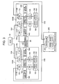
- FIG. 3 is an explanatory diagram showing the detailed hardware configuration of the respective virtualization storage devices 100A, 100B.
- the first virtualization storage device 100A may be configured by having a plurality of channel adapters (hereinafter referred to as a "CHA") 110, a plurality of disk adapters (hereinafter referred to as a "DKA”) 120, a cache memory 130, a control memory 140, a connection control unit 150, a memory unit 160, and a service processor (hereinafter abbreviated as "SVP”) 170.
- CHA channel adapters
- DKA disk adapters
- SVP service processor
- Each CHA 110 performs data communication with the host 10.
- Each CHA 110 may have at least one or more communication interfaces 111T for communicating with the host 10.
- Each CHA 110 may be configured as a microcomputer system equipped with a CPU, memory and so on.
- Each CHA 110 interprets and executes the various commands such as a read command or write command received from the host 10.
- Each CHA 110 is assigned a network address (e.g., IP address or WWN) for identifying the respective CHAs 110, and each CHA 110 may also individually function as a NAS (Network Attached Storage) .
- a network address e.g., IP address or WWN
- each CHA 110 receives and processes the request from each host 10 individually.
- a prescribed CHA 110 is provided with an interface (target port) 111T for communicating with the host 10
- the other CHAs 110 are provided with an interface (externally connected port) 111E for communicating with the external storage device 200.
- Each DKA 120 is used for transferring data to and from the disk drive 161 of the memory unit 160.
- Each DKA 120 as with the CHA 110, is configured as a microcomputer system equipped with a CPU, memory and so on.
- Each DKA 120 for example, is able to write data that the CHA 110 received from the host 10 or data read from the external storage device 200 into a prescribed disk drive 161. Further, each DKA 120 is also able to read data from a prescribed disk drive 161 and transmit this to the host 10 or external storage device 200.
- each DKA 120 converts a logical address into a physical address.
- each DKA 120 When the disk drive 161 is managed according to RAID, each DKA 120 performs data access according to such RAID configuration. For example, each DKA 120 respectively writes the same data in separate disk drive groups (RAID groups) (RAID 1, etc.), or executes a parity account and writes the data and parity in the disk drive group (RAID 5, etc.).
- RAID groups disk drive groups
- the respective virtualization storage devices 100A, 100B virtualize and incorporate the external volume 240 of the external storage device 200, and provides this to the host 10 as though it is one's own internal volume.
- the respective virtualization storage devices 100A, 100B do not necessarily have to have a memory unit 160.
- the respective virtualization storage devices 100A, 100B are used to virtualize and utilize the external volume 240.
- the DKA 120 will not be required.
- the configuration may also be such that one virtualization storage device has a memory unit 160, and the other virtualization storage device does not have a memory unit 160.
- the cache memory 130 stores the data received from the host 10 or external storage device 200. Further, the cache memory 130 stores data read from the disk drive 161. As described later, the memory space of the cache memory 130 is used to create a virtual, intermediate memory apparatus (V-VOL).
- V-VOL virtual, intermediate memory apparatus
- the control memory 140 stores various types of control information to be used in the operation of the virtualization storage device 100A. Further, a work area is set in the control memory 140, and various tables described later are also stored therein.
- one or a plurality of disk drives 161 may be used as the cache disk.
- the cache memory 130 and control memory 140 may be configured to be separate memories, or a part of the memory area of the same memory may be used as the cache area, and the other memory area may be used as the control area.
- connection control unit 150 mutually connects the respective CHAs 110, respective DKAs 120, cache memory 130 and control memory 140.
- the connection control unit 150 for instance, can be configured as a crossbar switch or the like.
- the memory unit 160 has a plurality of disk drives 161.
- the disk drive 161 for example, various memory apparatuses such as a hard disk drive, flexible disk drive, magnetic tape drive, semiconductor memory drive and optical disk drive as well as the equivalents thereof may be used. Further, for instance, different types of disks such as a FC (Fibre Channel) disk and a SATA (Serial AT Attachment) disk may coexist in the memory unit 160.
- FC Fibre Channel
- SATA Serial AT Attachment
- the service processor (SVP) 170 is respectively connected to each CHA 110 via an internal network such as a LAN.
- the SVP 170 is able to send and receive data to and from the control memory 140 or DKA 120 via the CHA 110.
- the SVP 170 extracts various types of information in the first virtualization storage device 100A and provides this to the management terminal 20.
- the second virtualization storage device 100B can also be configured the same as the first virtualization storage device 100A, the explanation thereof is omitted. Nevertheless, the respective virtualization storage devices 100A, 100B do not have to be configured the same.
- the external storage device 200 maybe configured approximately the same as the virtualization storage devices 100A, 100B, or may be configured more simple than the respective virtualization storage devices 100A, 100B.
- the upper level network CN1 connecting the host 10 and respective virtualization storage devices 100A, 100B and the lower level network CN2 mutually connecting the respective storage devices 100A, 100B, 200 are respectively configured as a separate communication network. Therefore, large quantities of data can be transferred with the lower level network CN2 without directly influencing the upper level network CN1.
- FIG. 4 is an explanatory diagram showing the memory configuration of the storage system. Foremost, the configuration of the virtualization storage devices 100A, 100B is explained taking the first virtualization storage device 100A as an example.
- the memory configuration of the first virtualization storage device 100A can be broadly classified into a physical memory hierarchy and a logical memory hierarchy.
- the physical memory hierarchy is configured from a PDEV (Physical Device) 161, which is a physical disk.
- PDEV corresponds to the foregoing disk drive 161.
- the logical memory hierarchy may be configured from a plurality of (e.g., two types of) hierarchies.
- One logical hierarchy may be configured from a VDEV (Virtual Device) 162, and a virtual VDEV (hereinafter sometimes referred to as "V-VOL") 163 which is treated like the VDEV 162.
- V-VOL virtual VDEV
- the other logical hierarchy may be configured from a LDEV (Logical Device) 164.
- the VDEV 162 is configured by grouping a prescribed number of PDEVs 161 such as in a set of fours (3D + 1P), or a set of eights (7D + 1P).
- the memory areas provided respectively from each PDEV 161 belonging to the group are assembled to form a single RAID storage area. This RAID memory area becomes the VDEV 162.
- the V-VOL 163 is a virtual intermediate memory apparatus that does not require a physical memory area.
- the V-VOL 163 is not directly associated with a physical memory area, and is a virtual existence to become the receiver for mapping an LU (Logical Unit) of the external storage controller device 200. This V-VOL 163 corresponds to an intermediate volume.
- At least one or more LDEVs 164 may be provided on the VDEV 162 or V-VOL 163.
- the LDEV 164 may be configured by dividing the VDEV 162 in a fixed length.
- the host 10 is an open host, by the LDEV 164 being mapped with the LU 165, the host 10 will recognize the LDEV 164 as a single physical disk.
- An open host can access a desired LDEV 164 by designating the LUN (Logical Unit Number) or logical block address.
- LUN Logical Unit Number
- a mainframe host will directly recognize the LDEV 164.
- the LU 165 is a device that can be recognized as a logical unit of SCSI.
- Each LU 165 is connected to the host 10 via the target port 111T.
- At least one or more LDEVs 164 may be respectively associated with each LU 165.
- the LU size can be virtually expanded.
- a CMD (Command Device) 166 is a dedicated LU to be used for transferring commands and statuses between the I/O control program operating on the host 10 and the storage device 100.
- a command from the host 10 is written in the CMD 166.
- the first virtualization storage device 100 executes the processing according to the command written in the CMD 166, and writes the execution result thereof as the status in the CMD 166.
- the host device 10 reads and confirms the status written in the CMD 166, and writes the processing contents to be executed subsequently in the CMD 166.
- the host device 10 is able to give various designations to the first virtualization storage device 100A via the CMD 166.
- the command received from the host device 10 may also be processed directly by the first virtualization storage device 100A without being stored in the CMD 166.
- the CMD may be created as a virtual device without defining the actual device (LU) and configured to receive and process the command from the host device 10.
- the CHA 110 writes the command received from the host device 10 in the control memory 140
- the CHA 110 or DKA 120 processes this command stored in the control memory 140.
- the processing results are written in the control memory 140, and transmitted from the CHA 110 to the host device 10.
- An external storage device 200 is connected to an initiator port (External Port) 111E for external connection of the first virtualization storage device 100A via the lower level network CN2.
- the external storage device 200 has a plurality of PDEVs 220, a VDEV 230 set on a memory area provided by the PDEV 220, and one or more LDEVs 240 that can be set on the VDEV 230. And, each LDEV 240 is respectively associated with the LU 250.
- the PDEV 220 corresponds to the disk drive 220 of FIG. 3 .
- the LDEV 240 corresponds to a "separate logical volume", and corresponds to the external volume 3A of FIG. 1 .
- the LU 250 (i.e., LDEV 240) of the external storage device 200 is mapped to the V-VOL 163.
- the "LDEV 1", “LDEV 2" of the external storage device 200 are respectively mapped to the "V-VOL 1", “V-VOL 2" of the first virtualization storage device 100A via the "LU 1", “LU 2" of the external storage device 200.
- "V-VOL 1", “V-VOL2" are respectively mapped to the "LDEV 3", "LDEV 4", and the host device 10 is thereby able to use these volumes via the "LU 3", "LU 4".
- the VDEV 162, V-VOL 163 may adopt the RAID configuration.
- a single disk drive 161 may be assigned to a plurality of VDEVs 162, V-VOLs 163 (slicing), and a single VDEV 162, V-VOL 163 may be formed from a plurality of disk drives 161 (striping).
- the second virtualization storage device 100B may have the same hierarchical memory configuration as the first virtualization storage device 100A, the explanation thereof is omitted.
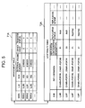
- FIG. 5 is an explanatory diagram showing the schematic configuration of the management table T1A and attribute table T2A used by the first virtualization storage device 100A. Each of these tables T1A, T2A may be stored in the control memory 140.
- the management table T1A is used for uniformly managing the respective external volumes 240 dispersed in the storage system.
- the management table T1A may be configured by respectively associating a network address (WWN: World Wide Name) for connected to the respective external volumes 240, a number (LUN: Logical Unit Number) of the respective external volumes 240, volume size of the respective external volumes 240, an external volume number, owner right information and transfer status flag.
- WWN World Wide Name
- LUN Logical Unit Number
- an external volume number is identifying information for uniquely specifying the respective external volumes 240 in the storage system.
- Owner right information is information for specifying the virtualization storage devices having the authority to use such external volume. When “0" is set in the owner right information, it shows that such external volume 240 is unused. When “1” is set in the owner right information, it shows that one's own device has the usage authorization to use such external volume 240. Further, when “-1" is set in the owner right information, it shows that the other virtualization storage devices have the usage authorization to use such external volume 240.
- the first virtualization storage device 100A has the usage authorization thereof.
- the second virtualization storage device 100B has the usage authorization thereof.
- the owner right information is set as "1" in one management table regarding a certain external volume 240
- the ownership right information of such external volume is set to "-1" in the other management table.
- the affiliation of such external volume 240 can be specified.
- the case number assigned to the respective virtualization storage devices may also be set.
- identifying information capable of uniquely specifying the respective virtualization storage devices in the storage system may be used as the owner right information.
- the transfer status flag is information showing that the external volume 240 is being transferred from one virtualization storage device to the other virtualization storage device.
- This shows that the owner right of such external volume 240 is being changed.
- "0" is set in the transfer status flag, this shows that such external volume 240 is in a normal state, and the owner right is not being changed.
- the attribute table T2A is a table for managing various types of attribute information of the respective external volumes 240.
- the attribute table T2A may be configured by associating the LU number of the respective external volumes 240, path definition information, replication configuration information, replication status information, and replication bitmap information.
- Path definition information is information for showing, via which port of which CHA 110, the logical volume 164 connected to such external volume 240 is to be accessed by the host 10.
- a plurality of paths may be set in the path definition information.
- One path is the normally used primary path, and the other path is an alternate path to be used when there is failure in the primary path.
- the replication configuration information is information showing the correspondence of the volumes configuring a copy-pair.
- a volume in which "P” is set in the replication configuration information is a primary volume (copy source volume), and a volume in which "S” is set in the replication configuration information is a secondary volume (copy destination volume).
- the numbers appended to "P" and "S" are serial numbers for identifying the respective copy-pairs.
- the replication status information is information showing the status of the respective volumes configuring the copy-pair.
- “Pair” is set in the replication status information
- the volume thereof is in synchronization with the volume of the other party, and shows that the respective volumes forming the copy-pair are maintaining the same memory contents.
- “Resync” is set in the replication status information
- this shows that the volume thereof and the volume of the other party are in resynchronization.
- “Simplex” is set in the replication status information, this shows that the volume thereof is not a target of replication.
- “Suspend” is set in the replication status information, this shows that the volume thereof has not been updated with the volume of the other party.
- the replication bitmap information is information showing the updated position of the data in the volume thereof. For example, a flag showing whether the data has been updated is prepared for each segment, and this means that, in a segment with "1" set to the flag, the data thereof has been updated.
- the size of the replication bitmap information will be 128KB.
- the total size of the replication bitmap information will be n ⁇ 128KB.
- n is 16384
- the table size of the attribute table T2A will be enormous. According, when the entirety of this attribute table T2A is to be transferred to the second virtualization storage device 100B, the control memory 140 of the second virtualization storage device 100B will be compressed. Thus, in the present embodiment, among the information stored in the attribute table T2A, only the information relating to the volume to be transferred to the second virtualization storage device 100B is transferred to the second virtualization storage device 100B. In other words, attribute information is transferred to the necessary extent. Thereby, the data volume to be transferred can be reduced, the time required for creating the attribute table can be shortened, and the compression of the memory resource (control memory 140) of the second virtualization storage device 100B, which is the transfer destination, can be prevented.
- information such as the device type (disc device or tape device, etc.), vendor name, identification number of the respective storage devices and so on may also be managed.
- Such information may be managed with either the management table T1A or attribute table T2A.
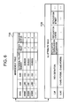
- FIG. 6 is an explanatory diagram showing the schematic configuration of the management table T1B and attribute table T2B used by the second virtualization storage device 100B.
- the management table T1B as with the management table T1A described above, for instance, is configured by associating a network address such as WWN, an LU number, volume size, an external volume number, owner right information and a transfer status flag.
- the management table T1A and management table T1B are configured the same excluding the owner right information.
- the attribute table T2B is also configured by associating an LU number, path definition information, replication configuration information, replication status information and replication bitmap information. Nevertheless, as described above, in order to effectively use the memory resource of the second virtualization storage device 100B, it should be noted that only the attribute information of the volume under the control of the second virtualization storage device 100B is registered in the management table T2B.
- FIG. 7 is an explanatory diagram showing the schematic configuration of the path setting information T3 to be used by the volume management unit 12 of the host 10.
- This path setting information T3 may be stored in the memory of the host 10 or a local disk.
- the path setting information T3 includes information relating to the primary path to be used in normal times, and information relating to the alternate path to be used in abnormal times.
- Each path for instance, is configured by including information for specifying the HBA 11 to be used, port number of the access destination, and LU number for identifying the volume of the access target.
- the alternate path described first is a normal alternate path
- the subsequently described alternate path is a path unique to the present embodiment.
- the second alternate path is a path set upon transferring the volume from the first virtualization storage device 100A to the second virtualization storage device 100B.
- FIG. 7 shows a frame format of the situation of switching from the primary path to the alternate path.
- the volume 420 of "#0" is transferred from the first virtualization storage device 100A to the second virtualization storage device 100B.
- the host 10 Before the transfer, by accessing the Port #0 from the HBA #0 as shown with the thick line in FIG. 7 , the host 10 is able to read and write data from and into the logical volume of the first virtualization storage device 100A.
- the external volume 240 is accessed from the Port #1 based on the access from the host 10.
- the second alternate path is a path to the second virtualization storage device 100B, which is the volume transfer destination.
- the second virtualization storage device 100B processes this access request, and returns the processing result to the host 10.
- the processible state of the access request means that even when the access request from the host 10 is processed, inconsistency in the data stored in the volume will not occur. This will be described in detail later.
- the host 10 when the host 10 is unsuccessful in accessing via the primary path, it switches to the first alternate path, and, when it is unsuccessful in accessing via the first alternate path, it switches to the second alternate path. Accordingly, until the access request of the host 10 is accepted, some time (path switching time) will be required. Nevertheless, this path switching time is not wasteful time. This is because, as described later, destage processing to the transferred volume can be performed during such path switching time. In the present embodiment, merely by adding a new path to the path setting information T3 stored in the host 10, the access destination of the host 10 can be switched.
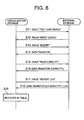
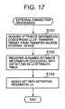
- FIG. 8 is a flowchart showing the outline of the processing for searching the external volume existing in the storage system and registering this in the management table T1A.
- FIG. 8 shows an example of a case where the first virtualization storage device 100A executes the processing.
- the first virtualization storage device 100A issues a command ("Test Unit Ready") toward the respective external storage devices 200 for confirming the existence thereof (S11).
- Test Unit Ready a command
- Each external storage device 200 operating normally will return a Ready reply having a Good status as the response to such command (S12).
- the first virtualization storage device 100A issues an "Inquiry" command to each external storage device 200 in which the existence thereof has been confirmed (S13).
- Each external storage device 200 that received this command for instance, transmits information regarding the device type and so on to the first virtualization storage device 100A (S14).
- the first virtualization storage device 100A issues a "Read Capacity" command to each external storage device 200 (S15).
- Each external storage device 200 transmits the size of the external volume 240 to the first virtualization storage device 100A (S16).
- the first virtualization storage device 100A transmits a "Report LUN" command to each external storage device 200 (S17).
- Each external storage device 200 transmits the LUN quantity and LUN number to the first virtualization storage device 100A (S18).
- the first virtualization storage device 100A registers the information acquired from each external storage device 200 in the management table T1A and attribute table T2A, respectively. As described above, the first virtualization storage device 100A is able to respectively create the management table T1A and attribute table T2A by issuing a plurality of inquiry commands.
- the configuration of the storage system may change by one of the external storage devices 200 being removed, or a new external storage device 200 being added.
- the first virtualization storage device 100A is able to detect such change in configuration based on command and notifications such as RSCN (Registered State Change Notification), LIP (Loop Initialization Primitive), SCR (State Change Registration) or SCN (State Change Notification).
- RSCN Registered State Change Notification
- LIP Loop Initialization Primitive
- SCR State Change Registration
- SCN State Change Notification
- the method of the virtualization storage devices 100A, 100B using the external volume 240 to process the access request from the host 10 is explained.
- the first virtualization storage device 100A processes the access request
- the second virtualization storage device 100B may also perform the same processing.
- the processing method of a write command is explained.
- the method for processing the write command two methods; namely, the synchronous transfer mode and asynchronous transfer mode may be considered.
- the first virtualization storage device 100A when the first virtualization storage device 100A receives a write command from the host 10, the first virtualization storage device 100A stores the write data received from the host 10 in the cache memory 130, and thereafter transfers the write data to the external storage device 200 via the communication network CN2.
- the external storage device 200 receives the write data and stores this in the cache memory, it transmits a reply signal to the first virtualization storage device 100A.
- the first virtualization storage device 100A receives the reply signal from the external storage device 200, it transmits a write completion report to the host 10.
- the synchronous transfer mode As described above, in the synchronous transfer mode, after the write data is transferred to the external storage device 200, the completion of the write command processing is notified to the host 10. Accordingly, in the synchronous transfer mode, a delay will arise in the time of waiting for the reply from the external storage device 200. Thus, the synchronous transfer mode is suitable in cases where the distance between the first virtualization storage device 100A and external storage device 200 is relatively short. Contrarily, if the first virtualization storage device 100A and external storage device 200 are far apart, generally speaking, the synchronous transfer mode is not suitable due to problems of delays in reply and delays in propagation.
- the first virtualization storage device 100A when the first virtualization storage device 100A receives a write command from the host 10, it stores the write data in the cache memory 130, and thereafter immediately issues a write completion report to the host 10. After issuing the write completion report to the host 10, the first virtualization storage device 100A transfers the write data to the external storage device 200.
- the write completion report to the host 10 and the data transfer to the external storage device 200 are conducted asynchronously. Accordingly, in the case of the asynchronous transfer mode, the write completion report can be transmitted to the host 10 quickly irrelevant to the distance between the first virtualization storage device 100A and external storage device 200.
- the asynchronous transfer mode is suitable when the distance between the first virtualization storage device 100A and external storage device 200 is relatively long.
- FIG. 9 is an explanatory diagram showing the case of the asynchronous transfermode.
- the virtualization storage devices 100A, 100B are not differentiated, and will be referred to as the "virtualization storage device 100".
- the management tables T1A, T1B are not differentiated, and will be referred to as the "management table T1".
- the host 10 issues a write command to a prescribed LU 165 of the virtualization storage devices 100 (S31).
- the LU 165 is associated with the LU 250 of the external storage device 200 via the V-VOL 163.
- the LU 165 of the virtualization storage devices 100 is an access target from the host 10, but the external LU 250 is actually storing the data. Therefore, for instance, the LU 165 may be referred to as an "access destination logical memory apparatus" and the LU 250 may be referred to as a "data storage destination logical memory apparatus", respectively.
- the virtualization storage devices 100 When the virtualization storage devices 100 receives a write command from the host 10, it specifies the LU targeted by such write command, refers to the management table T1 and determines whether this LU is associated with an external volume. When this is a write command to an LU associated with an external volume, the virtualization storage device 100 transmits a write command to the external storage device 200 having such external volume (S32).
- the host 10 transmits the write data with the LU 165 as the write target to the virtualization storage devices 100 (S33).
- the virtualization storage device 100 temporarily stores the write data received from the host 10 in the cache memory 130 (S34). After the virtualization storage device 100 stores the write data in the cache memory 130, it reports the completion of writing to the host 10 (S35).
- the virtualization storage device 100 transmits the write data stored in the cache memory 130 to the external storage device 200 (S36).
- the external storage device 200 stores the write data received from the virtualization storage device 100 in the cache memory.
- the external storage device 200 reports the completion of writing to the virtualization storage device 100 (S37).
- the external storage device 200 looks out for a period with few I/O, and writes the write data stored in the cache memory in the memory apparatus 220 (destage processing). In the asynchronous transfer mode, after write data is received from the host 10, the write completion can be sent to the host 10 in a short reply time ⁇ 1.
- FIG. 10 shows a case of the synchronous transfer mode.
- the virtualization storage device 100 Upon receiving the write command issued from the host 10 (S41), the virtualization storage device 100 specifies the external volume (LU 250) associated with the access destination volume (LU 165) of the write command, and issues a write command to such external volume (S42).
- the virtualization storage device 100 When the virtualization storage device 100 receives the write data from the host 10 (S43), it stores this write data in the cache memory 130 (S44). The virtualization storage device 100 transfers the write data stored in the cache memory 130 to the external storage device 200 such that it is written in the external volume (S45). After storing the write data in the cache memory, the external storage device 200 reports the completion of writing to the virtualization storage device 100 (S46). When the virtualization storage device 100 confirms the completion of writing in the external storage device 200, it reports the completion of writing to the host 10 (S47). In the synchronous transfer mode, since the report of the write completion to the host 10 is made upon waiting for the processing in the external storage device 200, the reply time ⁇ 2 will become long. The reply time ⁇ 2 of the synchronous transfer mode is longer than the reply time ⁇ 1 of the asynchronous transfer mode ( ⁇ 2 ⁇ 1).
- the respective virtualization storage devices 100A, 100B are able to incorporate and use the external volume 240 of the external storage device 200 as though it is a virtual internal volume.
- the external volume 240 may also be transferred from the second virtualization storage device 100B to the first virtualization storage device 100A.
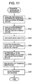
- FIG. 11 is a flowchart showing the processing for designating the transfer of the volume to the respective virtualization storage devices 100A, 100B.
- the monitoring unit 21 acquires performance information from the first virtualization storage device 100A (S51) .
- the monitoring unit 21 displays the acquired performance information on a terminal screen of the management terminal 20 (S52).
- This performance information corresponds to the information showing the "load status", and, for instance, includes the input/output per second (IOPS), CPU usage rate, cache memory usage rate and so on.
- IOPS input/output per second
- the user discovers whether there is a high-load CPU based on the performance information displayed on the screen of the management terminal 20 (S53). This CPU represents the CPU built in the CHA 110. Next, the user confirms that every CPU of other CHAs 110 is of a load that is greater than a prescribed value (S54).
- the user determines the transfer of the external volume 240 under the control of such CHA 110 (S55). Subsequently, the user sets a path of the transfer destination (S56). In other words, the user defines the path information regarding which port the host 10 will use for the access in the second virtualization storage device 100B, which is the transfer destination (S56). The defined path information is added to the host 10. Finally, the user designates the transfer of such external volume 240 to the respective virtualization storage devices 100A, 100B (S57).
- the user specifies the external volume that is being the bottleneck in the first virtualization storage device 100A, which is the transfer source (switching source) (S53 to S55) based on the monitoring result of the monitoring unit 21 (S51, S52), and designates the start of transfer by defining the path of the transfer destination (S56, S57).
- the transfer source switching source
- S56, S57 designates the start of transfer by defining the path of the transfer destination.
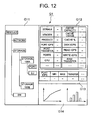
- FIG. 12 is an explanatory diagram showing an example of a screen showing the monitoring result of the monitoring unit 21.
- the monitoring unit 21 is able to respectively acquire performance information from the respective virtualization storage devices 100A, 100B, and display such performance information upon performing statistical processing or creating a graphical chart thereof.
- the selection unit G11 it is possible to select which load status regarding which resource among the various resources in the storage system is to be displayed.
- the resource for instance, "network”, “storage”, “switch” and so on may be considered.
- the user may further select one of the virtualization storage devices 100A, 100B. Further, when the user selects one of the virtualization storage devices 100A, 100B, the user may make a more detailed selection. As such detailed selection, "port” and “LU” may be considered. As described above, the user is able to select in detail the desired target for confirming the load status.
- the overall status of the selected virtualization storage device can be displayed as a list among the virtualization storage devices 100A, 100B.
- a more detailed monitoring target status such as the "port” and "LU"
- the load status can be displayed as a graph.
- the user is able to relatively easily determine which part of which virtualization storage device is a bottleneck based on the performance monitoring screen as shown in FIG. 12 .
- the user is able to determine the volume to be transferred based on such determination.
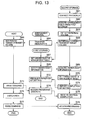
- FIG. 13 is a flowchart showing the situation of newly adding a second virtualization storage device 100B to the storage system in a state where the first virtualization storage device 100A is in operation, and transferring one or a plurality of volumes from the first virtualization storage device 100A to the second virtualization storage device 100B.
- the first virtualization storage device 100A is abbreviated as the "first storage”
- the second virtualization storage device 100B is abbreviated as the "second storage”, respectively.
- the user will be able to comprehend the load status of the first virtualization storage device 100A with the methods described with reference to FIG. 11 and FIG. 12 . As a result, the user will be able to determine the additional injection of the second virtualization storage device 100B.
- the user or engineer of the vendor performs physical connection procedures of the newly introduced second virtualization storage device 100B (S61). Specifically, the host connection interface 111T of the second virtualization storage device 100B is connected to the upper level network CN1, the external storage connection interface 111E of the second virtualization storage device 100B is connected to the lower level network CN2, and the SVP 170 of the second virtualization storage device 100B is connected to the network CN3.
- the second virtualization storage device 100B acquires the memory contents of the management table T1A from the first virtualization storage device 100A (S62). Based on such acquired contents, the second virtualization storage device 100B creates a management table T1B. The second virtualization storage device 100B respectively detects the external volumes 240 in the storage system based on the management table T1B (S63).
- the second virtualization storage device 100B connects the designated external volume 240 to the V-VOL 163 via the interface 111E (S65).
- the second virtualization storage device 100B acquires attribute information relating to the transfer target volume from the storage device of the transfer source; that is, the first virtualization storage device 100A (S151).
- the second virtualization storage device 100B registers the attribute information other than the path information among the acquired attribute information in the attribute table T2B (S152).
- the second virtualization storage device 100B newly sets path definition information regarding the transfer target volume (S153).
- the user selects the logical volume 164 to be accessed from the host 10 as the transfer target.
- the external volume 240 connected to such logical volume 164 will be reconnected to a separate logical volume 164 of the transfer destination storage device (100B).
- the virtualization storage devices 100A, 100B connect the external volume 240 to the logical volume 164 via the V-VOL 163, and are able to use this as though it is one's own internal memory apparatus.
- the volume management unit 12 of the host 10 adds the path information for accessing the transferred volume to the path setting information T3 (S66).
- path information for accessing the logical volume 164 connected to the external volume 240 via a prescribed port of the second virtualization storage device 100B is set.
- the first virtualization storage device 100A sets an owner right regarding the external volume 240 designated as the transfer target (S67). In other words, "-1" is set in the owner right information regarding the transfer target volume.
- the first virtualization storage device 100A notifies the set owner right information to the second virtualization storage device 100B (S68).
- the second virtualization storage device 100B acquires the owner right information from the first virtualization storage device 100A (S69), it registers the acquired owner right information in the management table T1B (S70).
- the owner right information is registered in the management table T1B upon the value thereof being changed to "1". This is because the usage authorization of the transfer target volume has been transferred to the second virtualization storage device 100B.
- the second virtualization storage device 100B reports the completion of registration of the owner right information to the first virtualization storage device 100A (S71).
- the first virtualization storage device 100A receives the setting completion report of the owner right information from the second virtualization storage device 100B (S72).
- the first virtualization storage device 100A starts the destage processing without processing the access request (S74). Access processing in the transfer source before the completion of transfer will be described later with reference to FIG. 14 .
- the second virtualization storage device 100B receives a notice indicating the completion of destage processing from the first virtualization storage device 100A (S75).
- the host 10 refers to the path setting information T3, switches to a different path (S76), and reissues the command (S77).
- the switch shall be from the primary path passing through the first virtualization storage device 100A to the second alternate path passing through the second virtualization storage device 100B.
- the second virtualization storage device 100B When the second virtualization storage device 100B receives a command from the host 10, it performs access processing (S78). If at the point in time of receiving the command the destage processing of the transfer target volume is complete, normal access processing will be performed. If the destage processing is not complete, however, different access processing will be performed. Access processing in the transfer destination before the completion of the transfer will be described later with reference to FIG. 15 . Incidentally, the flow shown in FIG. 13 is merely an example, and, in reality, there are cases where the order of steps will be different.
- FIG. 14 is a flowchart showing the details of S74 in FIG. 13 .
- the first virtualization storage device 100A which is the transfer source storage device, receives a command from the host 10 (S81: YES), it analyzes the access target of such command.
- the first virtualization storage device 100A determines whether the command in which the logical volume 164 connected to the external volume 240 of its own usage authorization is the access target (S82) . In other words, the first virtualization storage device 100A determines whether the command is an access request relating to the external volume 240 in which it has the owner right.
- the command processing from the host 10 is rejected (S83). Refection of the command processing, for instance, may be made by not replying for a prescribed period of time (negative rejection), or by notifying the host 10 that processing is impossible (positive rejection).
- the first virtualization storage device 100A starts the destage processing of dirty data regarding the external volume 240 in which the access was requested from the host 10 (S84). And, when the destage processing is complete (S85: YES), the first virtualization storage device 100A notifies the second virtualization storage device 100B to such effect (S86).
- the access target of the host 10 is the logical volume 164 of the first virtualization storage device 100A.
- the logical volume 164 is selected as the transfer target and, this logical volume 164 is connected to the logical volume 240 of the external storage device 200.
- the first virtualization storage device 100A is processing the write command in the asynchronous transfer mode. Accordingly, the first virtualization storage device 100A reports the completion of writing to the host 10 at the time the write data received from the host 10 is stored in the cache memory 130. The write data stored in the cache memory 130 is transferred to the external storage device 200 in a prescribed timing, and reflected in the external volume 240.
- the data stored in the cache memory 130 of the first virtualization storage device 100A and the data stored in the external volume 240 are different. Updated data regarding a certain segment or a segment group is stored in the cache memory 130, and old data before the update is regarding the same segment or segment group is stored in the external volume 240.
- dirty data data that is not reflected in the external volume 240 and which does not coincide with the memory contents of the cache memory 130 and the memory contents of the external volume 240.
- data in which write data is written in the external volume 240 and which coincides with the memory contents of the cache memory 130 and the memory contents of the external volume 240 is referred to as clean data.
- destage processing The processing of writing and reflecting the dirty data stored in the cache memory 130 of the first virtualization storage device 100A into the external volume 240 is referred to as destage processing.
- the first virtualization storage device 100A which is the transfer source, with perform destage processing without processing the access request from the host 10.
- the first virtualization storage device 100A identifies the type of command (S87), and performs normal access processing.
- the first virtualization storage device 100A stores the write data received from the host 10 in the cache memory 130 (S88), and notifies the host 10 of the completion of writing (S89). Next, while looking out for a prescribed timing, the first virtualization storage device 100A refers to the management table T1A, confirms the path to the external volume 240 (S90), and transfers the write data to the external volume 240 (S91).
- the first virtualization storage device 100A When it is a read command, the first virtualization storage device 100A reads the data requested from the host 10 from the external volume 240 (S92), and transfers this data to the host 10 (S93). Incidentally, when reading data from the external volume 240, the management table T1A is referred to. Further, when the data requested from the host 10 already exists on the cache memory 130 (when the data has been sliced), the first virtualization storage device 100A transfers the data stored in the cache memory 130 to the host 10 without accessing the external volume 240.
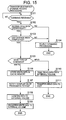
- FIG. 15 is a flowchart showing the details of S78 in FIG. 13 .
- the second virtualization storage device 100B which is the transfer destination, receives a command from the host 10 (S101: YES), it analyzes the access target of such command.
- the second virtualization storage device 100B determines whether the access target of the host 10 is a logical volume 164 connected to the external volume 240 under the control of the second virtualization storage device 100B (S102). In other words, the second virtualization storage device 100B determines whether the command is an access request relating to the external volume 240 in which it has the owner right thereof.
- the second virtualization storage device 100B determines whether this is an access request relating to the volume in which it has the owner right thereof (S102: YES), it determines whether the destage processing performed by the first virtualization storage device 100A regarding the external volume 240 connected to the logical volume 164 thereof is complete (S103). In other words, the second virtualization storage device 100B determines whether a destage completion notification has been acquired from the first virtualization storage device 100A regarding such volume.
- the second virtualization storage device 100B rejects the command processing (S104). This is in order to maintain the consistency of data regarding the transfer target volume.
- the second virtualization storage device 100B when the second virtualization storage device 100B has the owner right regarding the access target volume from the host 10 (S102: YES), and the destage processing at the transfer destination regarding the volume is complete (S103: YES), the second virtualization storage device 100B is able to perform the normal access processing.
- the normal access processing performed by the second virtualization storage device 100B is the same as the normal access processing performed by the first virtualization storage device 100A.
- the second virtualization storage device 100B distinguishes the type of command received from the host 10 (S105) .
- the second virtualization storage device 100B stores the write data received from the host 10 in the cache memory 130 (S106), and thereafter notifies the completion of writing to the host 10 (S107).
- the second virtualization storage device 100B refers to the management table T1B, confirms the path to the external volume 240 (S108), and transfers the write data stored in the cache memory 130 to the external volume and writes it therein (S109).
- the second virtualization storage device 100B When it is a read command, the second virtualization storage device 100B reads the data requested from the host 10 from the external volume 240 (or cache memory 130) (S110), and transfers this data to the host 10 (S111).
- the foregoing explanation is an example of newly introducing the second virtualization storage device 100B to the storage system. Next, a case of introducing the second virtualization storage device 100B and thereafter dispersing the load is explained.
- FIG. 16 is a flowchart showing a different example of transferring a volume between the respective virtualization storage devices 100A, 100B.
- the user is able to comprehend the operational status of the storage system based on the monitoring result of the monitoring unit 21. For example, when the user judges that the load of the first virtualization storage device 100A is heavy, the user may issue a designation so as to transfer the external volume 240 under the control of the first virtualization storage device 100A to the second virtualization storage device 100B via the management terminal 20 (S121). Further, a path for accessing via the second virtualization storage device 100B is added to the path setting information T3 of the host 10 based on the transfer designation from the management terminal 20.
- the first virtualization storage device 100A When the first virtualization storage device 100A receives a transfer designation from the management terminal 20, it changes the owner right of the external volume designated as the transfer target from "1" to "-1”, and notifies this change to the second virtualization storage device 100B (S122).
- the second virtualization storage device 100B When the second virtualization storage device 100B receives a notice from the first virtualization storage device 100A (S123), it sets "1" in the transfer status flag relating to the transfer target volume and updates the management table T1B (S124), and notifies the completion of setting of the transfer status flag to the first virtualization storage device 100A (S125).
- the first virtualization storage device 100A When the first virtualization storage device 100A receives a notice from the second virtualization storage device 100B, similarly, it sets "1" in the transfer status flag relating to the transfer target volume and updates the management table T1A (S126) . And, the first virtualization storage device 100A starts the destage processing of dirty data relating to the transfer target volume (S127).
- the first virtualization storage device 100A will reject such processing (S129).
- the host 10 When the access processing is rejected by the first virtualization storage device 100A, the host 10 refers to the path setting information T3 and switches the path (S130).
- the explanation is regarding a case of switching from the primary path passing through the first virtualization storage device 100A to the alternate path passing through the second virtualization storage device 100B.
- the host 10 After switching the path, the host 10 reissues the command (S131).
- This command may be a write command or a read command, and let it be assumed that a write command has been issued for the sake of convenience of explanation.
- the second virtualization storage device 100B When the second virtualization storage device 100B receives a write command from the host 10 (S132), it receives write data transmitted from the host 10 after the write command, and stores this in the cache memory 130 (S132). After storing the write data in the cache memory 130, the second virtualization storage device 100B reports the completion of writing to the host 10 (S133). The host 10 receives a processing completion notice from the second virtualization storage device 100B (S134).
- the first virtualization storage device 100A notifies the completion of the destage processing to the second virtualization storage device 100B (S136).
- the second virtualization storage device 100B receives this destage completion notice (S137), it resets the transfer status flag relating to the transfer target volume (S138). Thereby, the transfer of the volume is completed while maintaining the consistency of the volume.
- the second virtualization storage device 100B performs the normal access processing (S140).
- the second virtualization storage device 100B may reject the processing of the read command until the destage processing by the first virtualization storage device 100A is complete.
- FIG. 18 is an explanatory diagram showing a frame format of the situation of transferring the volume according to the present embodiment. Foremost, as shown in FIG. 18(a) , let it be assumed that only the first virtualization storage device 100A is initially operating in the storage system. Under these circumstances, the first virtualization storage device 100A is using all external volumes 240.
- the user determines the introduction of the second virtualization storage device 100B based on the load status of the first virtualization storage device 100A, and adds the second virtualization storage device 100B to the storage system.
- a plurality of virtualization storage devices 100A, 100B may be used to manage each of the external volumes 240. Accordingly, the load in the storage system can be dispersed and the processing performance of the overall storage system can be improved.
- the external volume 240 can be transferred between the respective virtualization storage devices 100A, 100B without stopping the access from the host 10. Therefore, the volume can be transferred via online without having to shut down the host 10, and the usability will improve.
- the user merely needs to make a designation via the management terminal 20 to transfer the external volume 240 between the respective virtualization storage devices 100A, 100B. Accordingly, in a storage system having a plurality of virtualization storage devices 100A, 100B capable of virtualizing and using the external volume 240, the performance of the storage system can be improved with a relatively simple operation.
- the virtualization storage device 100A which is the transfer source, is configured such that it can reject the access request from the host 10 until the destage processing relating to the transfer target external volume 240 is complete. Therefore, the volume can be transferred while maintaining the consistency of data.
- the second embodiment of the present invention is now explained with reference to FIG. 19 .
- the present embodiment corresponds to a modified example of the foregoing first embodiment.
- the storage system autonomously disperses the load between the respective virtualization storage devices 100A, 100B.
- FIG. 19 is a flowchart of the transfer designation processing according to the present embodiment.
- This transfer designation processing can be executed with the management terminal 20.
- the management terminal 20 acquires the performance information from the respective virtualization storage devices 100A, 100B (S161).
- the management terminal 20 compares the load LS1 of the first virtualization storage device 100A and the load LS2 of the second virtualization storage device 100B (S163). When the first load LS1 is greater than the second load LS2 (LS1 > LS2), the management terminal 20 determines the logical volume (external volume) to the transferred from the first virtualization storage device 100A to the second virtualization storage device 100B (S164). The management terminal 20, for instance, may select the volume of the highest load in the device.
- the management terminal 20 judges whether the transfer timing has arrived (S165), and, when the transfer timing has arrived (S165: YES), it defines the path information of the transfer destination (S166), and respectively issues a transfer designation to the respective virtualization storage devices 100A, 100B (S166). For example, a time frame with low access frequency from the host 10 may be pre-selected as the transfer timing.
- the management terminal 20 determines the volume to be transferred from the second virtualization storage device 100B to the first virtualization storage device 100A (S168).
- the management terminal 20 looks out for a prescribed transfer timing (S169: YES), defines the path of the transfer destination (S170), and respectively issues a transfer designation to the respective virtualization storage devices 100A, 100B (S171).
- the present embodiment configured as described above also yields the same effects as the foregoing embodiments.
- the load dispersion between the plurality of virtualization storage devices 100A, 100B capable of respectively virtualizing the external volume 240 can be performed autonomously.
- the present invention is not limited to the embodiments described above. Those skilled in the art may make various additions and modifications within the scope of the present invention.
- the configuration may also be such that all external volumes are transferred to the second virtualization storage device, and the first virtualization storage device may be entirely replaced with the second virtualization storage device.
- the present invention is not limited thereto, and the configuration may be such that the function of the management terminal is built in one of the virtualization storage devices.
- the logical volume 164 of the transfer source and the logical volume 164 of the transfer destination will be set to be of the same size.
Priority Applications (1)
| Application Number | Priority Date | Filing Date | Title |
|---|---|---|---|
| EP15180033.1A EP2975513B1 (en) | 2005-05-24 | 2005-12-07 | Storage system and operation method of storage system |
Applications Claiming Priority (2)
| Application Number | Priority Date | Filing Date | Title |
|---|---|---|---|
| JP2005150868A JP5057656B2 (ja) | 2005-05-24 | 2005-05-24 | ストレージシステム及びストレージシステムの運用方法 |
| EP05257515A EP1727033A1 (en) | 2005-05-24 | 2005-12-07 | Storage system and operation method of storage system |
Related Parent Applications (2)
| Application Number | Title | Priority Date | Filing Date |
|---|---|---|---|
| EP05257515A Division EP1727033A1 (en) | 2005-05-24 | 2005-12-07 | Storage system and operation method of storage system |
| EP05257515.6 Division | 2005-12-07 |
Related Child Applications (2)
| Application Number | Title | Priority Date | Filing Date |
|---|---|---|---|
| EP15180033.1A Division-Into EP2975513B1 (en) | 2005-05-24 | 2005-12-07 | Storage system and operation method of storage system |
| EP15180033.1A Division EP2975513B1 (en) | 2005-05-24 | 2005-12-07 | Storage system and operation method of storage system |
Publications (3)
| Publication Number | Publication Date |
|---|---|
| EP2246777A2 EP2246777A2 (en) | 2010-11-03 |
| EP2246777A3 EP2246777A3 (en) | 2010-12-22 |
| EP2246777B1 true EP2246777B1 (en) | 2015-10-28 |
Family
ID=36450094
Family Applications (3)
| Application Number | Title | Priority Date | Filing Date |
|---|---|---|---|
| EP05257515A Ceased EP1727033A1 (en) | 2005-05-24 | 2005-12-07 | Storage system and operation method of storage system |
| EP15180033.1A Active EP2975513B1 (en) | 2005-05-24 | 2005-12-07 | Storage system and operation method of storage system |
| EP10008469.8A Active EP2246777B1 (en) | 2005-05-24 | 2005-12-07 | Storage system and operation method of storage system |
Family Applications Before (2)
| Application Number | Title | Priority Date | Filing Date |
|---|---|---|---|
| EP05257515A Ceased EP1727033A1 (en) | 2005-05-24 | 2005-12-07 | Storage system and operation method of storage system |
| EP15180033.1A Active EP2975513B1 (en) | 2005-05-24 | 2005-12-07 | Storage system and operation method of storage system |
Country Status (4)
| Country | Link |
|---|---|
| US (5) | US20060271758A1 (ja) |
| EP (3) | EP1727033A1 (ja) |
| JP (1) | JP5057656B2 (ja) |
| CN (2) | CN100395694C (ja) |
Families Citing this family (82)
| Publication number | Priority date | Publication date | Assignee | Title |
|---|---|---|---|---|
| US8032701B1 (en) | 2004-03-26 | 2011-10-04 | Emc Corporation | System and method for managing provisioning of storage resources in a network with virtualization of resources in such a network |
| US8219681B1 (en) | 2004-03-26 | 2012-07-10 | Emc Corporation | System and method for managing provisioning of storage resources in a network with virtualization of resources in such a network |
| US8281022B1 (en) | 2000-06-30 | 2012-10-02 | Emc Corporation | Method and apparatus for implementing high-performance, scaleable data processing and storage systems |
| US7818517B1 (en) | 2004-03-26 | 2010-10-19 | Emc Corporation | Architecture for virtualization of networked storage resources |
| US8627005B1 (en) | 2004-03-26 | 2014-01-07 | Emc Corporation | System and method for virtualization of networked storage resources |
| US7770059B1 (en) | 2004-03-26 | 2010-08-03 | Emc Corporation | Failure protection in an environment including virtualization of networked storage resources |
| US8140665B2 (en) * | 2005-08-19 | 2012-03-20 | Opnet Technologies, Inc. | Managing captured network traffic data |
| JP4842593B2 (ja) * | 2005-09-05 | 2011-12-21 | 株式会社日立製作所 | ストレージ仮想化装置のデバイス制御引継ぎ方法 |
| US7702851B2 (en) * | 2005-09-20 | 2010-04-20 | Hitachi, Ltd. | Logical volume transfer method and storage network system |
| JP2007094578A (ja) * | 2005-09-27 | 2007-04-12 | Fujitsu Ltd | ストレージシステム及びその構成部品交換処理方法 |
| JP2007280111A (ja) * | 2006-04-07 | 2007-10-25 | Hitachi Ltd | ストレージシステム及びその性能チューニング方法 |
| JP2007280089A (ja) * | 2006-04-07 | 2007-10-25 | Hitachi Ltd | 容量拡張ボリュームの移行方法 |
| JP4963892B2 (ja) * | 2006-08-02 | 2012-06-27 | 株式会社日立製作所 | 仮想ストレージシステムの構成要素となることが可能なストレージシステムの制御装置 |
| JP4331742B2 (ja) | 2006-10-25 | 2009-09-16 | 株式会社日立製作所 | I/oの割り振り比率に基づいて性能を管理する計算機システム、計算機及び方法 |
| JP5057366B2 (ja) | 2006-10-30 | 2012-10-24 | 株式会社日立製作所 | 情報システム及び情報システムのデータ転送方法 |
| JP4897499B2 (ja) * | 2007-01-19 | 2012-03-14 | 株式会社日立製作所 | 記憶システム又はストレージ移行方法 |
| JP2008217364A (ja) * | 2007-03-02 | 2008-09-18 | Nec Corp | ファイル入出力調整制御システム、ファイル入出力調整制御方法、ファイル入出力調整制御プログラム |
| US7877556B2 (en) * | 2007-03-30 | 2011-01-25 | Hitachi, Ltd. | Method and apparatus for a unified storage system |
| US8990527B1 (en) * | 2007-06-29 | 2015-03-24 | Emc Corporation | Data migration with source device reuse |
| JP2009026255A (ja) * | 2007-07-24 | 2009-02-05 | Hitachi Ltd | データ移行方法、データ移行システム、及びデータ移行プログラム |
| JP4958673B2 (ja) * | 2007-07-26 | 2012-06-20 | 株式会社日立製作所 | ストレージシステム及びこれの管理方法 |
| US20090089498A1 (en) * | 2007-10-02 | 2009-04-02 | Michael Cameron Hay | Transparently migrating ongoing I/O to virtualized storage |
| JP2009146106A (ja) * | 2007-12-13 | 2009-07-02 | Hitachi Ltd | 物理的な通信ポートに付加される仮想的な通信ポートを移行する機能を有したストレージシステム |
| JP5259626B2 (ja) * | 2007-12-26 | 2013-08-07 | キヤノンアネルバ株式会社 | スパッタ装置、スパッタ成膜方法 |
| JP4674242B2 (ja) * | 2008-02-05 | 2011-04-20 | 富士通株式会社 | 仮想化スイッチ、コンピュータシステムおよびデータコピー方法 |
| US20090240880A1 (en) * | 2008-03-21 | 2009-09-24 | Hitachi, Ltd. | High availability and low capacity thin provisioning |
| US8156297B2 (en) * | 2008-04-15 | 2012-04-10 | Microsoft Corporation | Smart device recordation |
| US8347046B2 (en) * | 2008-04-15 | 2013-01-01 | Microsoft Corporation | Policy framework to treat data |
| US8082411B1 (en) * | 2008-04-30 | 2011-12-20 | Netapp, Inc. | Method and system for logical unit substitution |
| US8032730B2 (en) * | 2008-05-15 | 2011-10-04 | Hitachi, Ltd. | Method and apparatus for I/O priority control in storage systems |
| JP5272185B2 (ja) * | 2008-09-26 | 2013-08-28 | 株式会社日立製作所 | 計算機システム及びストレージシステム |
| US8700215B2 (en) | 2009-01-13 | 2014-04-15 | Panasonic Corporation | Control apparatus and control method of elastic body actuator as well as control program thereof |
| CN101877136A (zh) * | 2009-04-30 | 2010-11-03 | 国际商业机器公司 | 处理图形对象的方法、设备及系统 |
| US8499098B2 (en) * | 2009-10-09 | 2013-07-30 | Hitachi, Ltd. | Storage system and storage system communication path management method |
| US8639769B2 (en) | 2009-12-18 | 2014-01-28 | International Business Machines Corporation | Handling of data transfer in a LAN-free environment |
| CN101788889B (zh) * | 2010-03-03 | 2011-08-10 | 浪潮(北京)电子信息产业有限公司 | 一种存储虚拟化系统及方法 |
| US8266192B2 (en) * | 2010-03-19 | 2012-09-11 | Hitachi, Ltd. | File-sharing system and method for processing files, and program |
| WO2011125106A1 (en) * | 2010-04-05 | 2011-10-13 | Hitachi, Ltd. | Storage system configured from plurality of storage modules and method for switching coupling configuration of storage modules |
| JP5065434B2 (ja) * | 2010-04-06 | 2012-10-31 | 株式会社日立製作所 | 管理方法及び管理装置 |
| CN102754090B (zh) | 2010-06-17 | 2015-09-16 | 株式会社日立制作所 | 包括多个微处理器的存储系统以及用于在该存储系统中分担处理的方法 |
| WO2012007999A1 (en) | 2010-07-16 | 2012-01-19 | Hitachi, Ltd. | Storage control apparatus and storage system comprising multiple storage control apparatuses |
| JP5602572B2 (ja) * | 2010-10-06 | 2014-10-08 | 富士通株式会社 | ストレージ装置、データ複写方法およびストレージシステム |
| US8627033B2 (en) * | 2010-12-20 | 2014-01-07 | Microsoft Corporation | Storage device migration and redirection |
| IL210169A0 (en) | 2010-12-22 | 2011-03-31 | Yehuda Binder | System and method for routing-based internet security |
| WO2012085975A1 (en) | 2010-12-22 | 2012-06-28 | Hitachi, Ltd. | Storage system comprising multiple storage apparatuses with both storage virtualization function and capacity virtualization function |
| WO2012093417A1 (en) | 2011-01-05 | 2012-07-12 | Hitachi, Ltd. | Storage system comprising multiple storage control apparatus units for processing an i/o command from a host |
| US9021198B1 (en) * | 2011-01-20 | 2015-04-28 | Commvault Systems, Inc. | System and method for sharing SAN storage |
| JP5455945B2 (ja) * | 2011-02-14 | 2014-03-26 | 株式会社東芝 | 調停装置、記憶装置、情報処理装置およびプログラム |
| WO2012114384A1 (en) * | 2011-02-25 | 2012-08-30 | Hitachi, Ltd. | Storage system and method of controlling the storage system |
| WO2012172601A1 (en) | 2011-06-14 | 2012-12-20 | Hitachi, Ltd. | Storage system comprising multiple storage control apparatus |
| US9740435B2 (en) * | 2012-02-27 | 2017-08-22 | Fujifilm North America Corporation | Methods for managing content stored in cloud-based storages |
| WO2013160933A1 (en) * | 2012-04-23 | 2013-10-31 | Hitachi, Ltd. | Computer system and virtual server migration control method for computer system |
| US11055124B1 (en) * | 2012-09-30 | 2021-07-06 | EMC IP Holding Company LLC | Centralized storage provisioning and management across multiple service providers |
| WO2014054070A1 (en) * | 2012-10-03 | 2014-04-10 | Hitachi, Ltd. | Management system for managing a physical storage system, method of determining a resource migration destination of a physical storage system, and storage medium |
| DE102012110164B4 (de) * | 2012-10-24 | 2021-08-19 | Fujitsu Ltd. | Rechneranordnung |
| JP6357780B2 (ja) * | 2013-02-06 | 2018-07-18 | 株式会社リコー | ネットワークシステム及び情報通知方法 |
| US20140281673A1 (en) * | 2013-03-15 | 2014-09-18 | Unisys Corporation | High availability server configuration |
| US9003087B2 (en) | 2013-03-18 | 2015-04-07 | Hitachi, Ltd. | Compound storage system and storage control method |
| JP6114397B2 (ja) * | 2013-03-18 | 2017-04-12 | 株式会社日立製作所 | 複合型ストレージシステム及び記憶制御方法 |
| JP6186787B2 (ja) * | 2013-03-25 | 2017-08-30 | 富士通株式会社 | データ転送装置、データ転送システム、データ転送方法及びプログラム |
| JP2014215666A (ja) * | 2013-04-23 | 2014-11-17 | 富士通株式会社 | 制御システム,制御装置及び制御プログラム |
| JP6209863B2 (ja) * | 2013-05-27 | 2017-10-11 | 富士通株式会社 | ストレージ制御装置、ストレージ制御方法およびストレージ制御プログラム |
| EP3039831A1 (en) * | 2013-08-30 | 2016-07-06 | Nokia Solutions and Networks Oy | Methods and apparatus |
| US8954614B1 (en) * | 2013-12-06 | 2015-02-10 | Concurrent Ventures, LLC | System, method and article of manufacture for monitoring, controlling and improving storage media system performance based on temperature |
| US10048895B2 (en) | 2013-12-06 | 2018-08-14 | Concurrent Ventures, LLC | System and method for dynamically load balancing storage media devices based on a mid-range performance level |
| US9436404B2 (en) | 2013-12-06 | 2016-09-06 | Concurrent Ventures, LLC | System and method for dynamically load balancing across storage media devices having fast access rates |
| US10235096B2 (en) | 2013-12-06 | 2019-03-19 | Concurrent Ventures, LLC | System and method for dynamically load balancing storage media devices based on an average or discounted average sustained performance level |
| US8984172B1 (en) * | 2013-12-06 | 2015-03-17 | Concurrent Ventures, LLC | System, method and article of manufacture for monitoring, controlling and improving storage media system performance based on storage media device fill percentage |
| US8954615B1 (en) * | 2013-12-06 | 2015-02-10 | Concurrent Ventures, LLC | System, method and article of manufacture for monitoring, controlling and improving storage media system performance based on temperature ranges |
| US9274722B2 (en) * | 2013-12-06 | 2016-03-01 | Concurrent Ventures, LLP | System, method and article of manufacture for monitoring, controlling and improving storage media system performance |
| JP2015184895A (ja) * | 2014-03-24 | 2015-10-22 | 富士通株式会社 | ストレージ制御装置、ストレージ装置、及びストレージ制御プログラム |
| JP6336813B2 (ja) * | 2014-04-16 | 2018-06-06 | 富士通株式会社 | ストレージ仮想化装置、ストレージ仮想化装置の制御方法及び制御プログラム |
| JP6361390B2 (ja) * | 2014-09-10 | 2018-07-25 | 富士通株式会社 | ストレージ制御装置および制御プログラム |
| WO2016209313A1 (en) * | 2015-06-23 | 2016-12-29 | Hewlett-Packard Development Company, L.P. | Task execution in a storage area network (san) |
| US10101915B2 (en) | 2015-06-24 | 2018-10-16 | Vmware, Inc. | Methods and apparatus to manage inter-virtual disk relations in a modularized virtualization topology using virtual hard disks |
| US9928010B2 (en) | 2015-06-24 | 2018-03-27 | Vmware, Inc. | Methods and apparatus to re-direct detected access requests in a modularized virtualization topology using virtual hard disks |
| US10126983B2 (en) | 2015-06-24 | 2018-11-13 | Vmware, Inc. | Methods and apparatus to enforce life cycle rules in a modularized virtualization topology using virtual hard disks |
| US9804789B2 (en) * | 2015-06-24 | 2017-10-31 | Vmware, Inc. | Methods and apparatus to apply a modularized virtualization topology using virtual hard disks |
| CN107038333B (zh) * | 2016-01-21 | 2021-10-26 | 株式会社堀场制作所 | 测量设备的管理装置 |
| US10437477B2 (en) * | 2017-07-20 | 2019-10-08 | Dell Products, Lp | System and method to detect storage controller workloads and to dynamically split a backplane |
| JP6878369B2 (ja) * | 2018-09-03 | 2021-05-26 | 株式会社日立製作所 | ボリューム配置管理装置、ボリューム配置管理方法、及びボリューム配置管理プログラム |
| JP2021047786A (ja) | 2019-09-20 | 2021-03-25 | 富士通株式会社 | ストレージ制御装置、ストレージ装置及び決定プログラム |
Citations (1)
| Publication number | Priority date | Publication date | Assignee | Title |
|---|---|---|---|---|
| GB2406406A (en) * | 2003-09-29 | 2005-03-30 | Hitachi Ltd | Storage system and storage controller |
Family Cites Families (43)
| Publication number | Priority date | Publication date | Assignee | Title |
|---|---|---|---|---|
| JP3021955B2 (ja) * | 1992-05-13 | 2000-03-15 | 富士通株式会社 | 二重化ファイルシステム運用方法 |
| JPH09197367A (ja) * | 1996-01-12 | 1997-07-31 | Sony Corp | プラズマアドレス表示装置 |
| US6886035B2 (en) * | 1996-08-02 | 2005-04-26 | Hewlett-Packard Development Company, L.P. | Dynamic load balancing of a network of client and server computer |
| JP3410010B2 (ja) | 1997-12-24 | 2003-05-26 | 株式会社日立製作所 | サブシステムの移行方法および情報処理システム |
| US6101508A (en) * | 1997-08-01 | 2000-08-08 | Hewlett-Packard Company | Clustered file management for network resources |
| US6067545A (en) * | 1997-08-01 | 2000-05-23 | Hewlett-Packard Company | Resource rebalancing in networked computer systems |
| US5889520A (en) * | 1997-11-13 | 1999-03-30 | International Business Machines Corporation | Topological view of a multi-tier network |
| JP3726484B2 (ja) | 1998-04-10 | 2005-12-14 | 株式会社日立製作所 | 記憶サブシステム |
| WO1999060564A2 (en) | 1998-05-15 | 1999-11-25 | Storage Technology Corporation | Caching method for data blocks of variable size |
| JP4412685B2 (ja) | 1998-09-28 | 2010-02-10 | 株式会社日立製作所 | 記憶制御装置及びこれを用いたデータ格納システムの取り扱い方法 |
| JP2000316132A (ja) | 1999-04-30 | 2000-11-14 | Matsushita Electric Ind Co Ltd | ビデオサーバ |
| US6766430B2 (en) * | 2000-07-06 | 2004-07-20 | Hitachi, Ltd. | Data reallocation among storage systems |
| US6457109B1 (en) * | 2000-08-18 | 2002-09-24 | Storage Technology Corporation | Method and apparatus for copying data from one storage system to another storage system |
| US6675268B1 (en) | 2000-12-11 | 2004-01-06 | Lsi Logic Corporation | Method and apparatus for handling transfers of data volumes between controllers in a storage environment having multiple paths to the data volumes |
| US6732104B1 (en) * | 2001-06-06 | 2004-05-04 | Lsi Logic Corporatioin | Uniform routing of storage access requests through redundant array controllers |
| US7613806B2 (en) * | 2001-06-28 | 2009-11-03 | Emc Corporation | System and method for managing replication sets of data distributed over one or more computer systems |
| US7707304B1 (en) | 2001-09-28 | 2010-04-27 | Emc Corporation | Storage switch for storage area network |
| JP2005505819A (ja) | 2001-09-28 | 2005-02-24 | マランティ ネットワークス インコーポレイテッド | 記憶システムにおけるパケットの分類 |
| US7864758B1 (en) | 2001-09-28 | 2011-01-04 | Emc Corporation | Virtualization in a storage system |
| US7404000B2 (en) * | 2001-09-28 | 2008-07-22 | Emc Corporation | Protocol translation in a storage system |
| US7185062B2 (en) * | 2001-09-28 | 2007-02-27 | Emc Corporation | Switch-based storage services |
| US6976134B1 (en) * | 2001-09-28 | 2005-12-13 | Emc Corporation | Pooling and provisioning storage resources in a storage network |
| US20030079018A1 (en) * | 2001-09-28 | 2003-04-24 | Lolayekar Santosh C. | Load balancing in a storage network |
| US7421509B2 (en) * | 2001-09-28 | 2008-09-02 | Emc Corporation | Enforcing quality of service in a storage network |
| JP2003162377A (ja) | 2001-11-28 | 2003-06-06 | Hitachi Ltd | ディスクアレイシステム及びコントローラ間での論理ユニットの引き継ぎ方法 |
| JP4220174B2 (ja) * | 2002-04-08 | 2009-02-04 | 株式会社日立製作所 | ストレージシステムのコンテンツ更新方法 |
| JP2003316522A (ja) * | 2002-04-26 | 2003-11-07 | Hitachi Ltd | 計算機システムおよび計算機システムの制御方法 |
| JP4704659B2 (ja) | 2002-04-26 | 2011-06-15 | 株式会社日立製作所 | 記憶装置システムの制御方法および記憶制御装置 |
| JP4100968B2 (ja) * | 2002-06-06 | 2008-06-11 | 株式会社日立製作所 | データマッピング管理装置 |
| JP4214832B2 (ja) * | 2002-07-30 | 2009-01-28 | 株式会社日立製作所 | 記憶装置システム |
| US7103727B2 (en) | 2002-07-30 | 2006-09-05 | Hitachi, Ltd. | Storage system for multi-site remote copy |
| JP2004102374A (ja) | 2002-09-05 | 2004-04-02 | Hitachi Ltd | データ移行装置を有する情報処理システム |
| US7509645B2 (en) * | 2002-10-17 | 2009-03-24 | Intel Corporation | Methods and apparatus for load balancing storage nodes in a distributed network attached storage system |
| JP2004178253A (ja) * | 2002-11-27 | 2004-06-24 | Hitachi Ltd | 記憶デバイス制御装置および記憶デバイス制御装置の制御方法 |
| JP2004220450A (ja) | 2003-01-16 | 2004-08-05 | Hitachi Ltd | ストレージ装置、その導入方法、及びその導入プログラム |
| JP4409181B2 (ja) * | 2003-01-31 | 2010-02-03 | 株式会社日立製作所 | 画面データ生成方法、コンピュータ、プログラム |
| JP2004302751A (ja) * | 2003-03-31 | 2004-10-28 | Hitachi Ltd | 計算機システムの性能管理方法、および、記憶装置の性能を管理する計算機システム |
| JP2005018161A (ja) | 2003-06-23 | 2005-01-20 | Adtex:Kk | 記憶システム、制御方法、及びプログラム |
| JP4462852B2 (ja) * | 2003-06-23 | 2010-05-12 | 株式会社日立製作所 | ストレージシステム及びストレージシステムの接続方法 |
| JP2005055963A (ja) * | 2003-08-05 | 2005-03-03 | Hitachi Ltd | ボリューム制御方法、この方法を実行するプログラム、及びストレージ装置 |
| US20050257014A1 (en) * | 2004-05-11 | 2005-11-17 | Nobuhiro Maki | Computer system and a management method of a computer system |
| JP3781378B2 (ja) * | 2005-01-04 | 2006-05-31 | 株式会社日立製作所 | 記憶サブシステム |
| US7337350B2 (en) | 2005-02-09 | 2008-02-26 | Hitachi, Ltd. | Clustered storage system with external storage systems |
-
2005
- 2005-05-24 JP JP2005150868A patent/JP5057656B2/ja not_active Expired - Fee Related
- 2005-07-15 US US11/181,877 patent/US20060271758A1/en not_active Abandoned
- 2005-12-07 EP EP05257515A patent/EP1727033A1/en not_active Ceased
- 2005-12-07 EP EP15180033.1A patent/EP2975513B1/en active Active
- 2005-12-07 EP EP10008469.8A patent/EP2246777B1/en active Active
-
2006
- 2006-03-03 CN CNB2006100568049A patent/CN100395694C/zh active Active
- 2006-03-03 CN CN200810095344.XA patent/CN101271382B/zh active Active
-
2009
- 2009-02-09 US US12/367,706 patent/US8180979B2/en active Active
-
2010
- 2010-07-06 US US12/830,865 patent/US7953942B2/en not_active Expired - Fee Related
-
2011
- 2011-08-31 US US13/222,569 patent/US8484425B2/en active Active
-
2013
- 2013-06-07 US US13/912,297 patent/US20130275690A1/en not_active Abandoned
Patent Citations (1)
| Publication number | Priority date | Publication date | Assignee | Title |
|---|---|---|---|---|
| GB2406406A (en) * | 2003-09-29 | 2005-03-30 | Hitachi Ltd | Storage system and storage controller |
Also Published As
| Publication number | Publication date |
|---|---|
| EP2246777A2 (en) | 2010-11-03 |
| US20060271758A1 (en) | 2006-11-30 |
| US20130275690A1 (en) | 2013-10-17 |
| JP5057656B2 (ja) | 2012-10-24 |
| EP2246777A3 (en) | 2010-12-22 |
| US20110314250A1 (en) | 2011-12-22 |
| CN1869914A (zh) | 2006-11-29 |
| CN100395694C (zh) | 2008-06-18 |
| US8484425B2 (en) | 2013-07-09 |
| EP1727033A1 (en) | 2006-11-29 |
| US20100274963A1 (en) | 2010-10-28 |
| EP2975513A1 (en) | 2016-01-20 |
| US8180979B2 (en) | 2012-05-15 |
| US7953942B2 (en) | 2011-05-31 |
| CN101271382A (zh) | 2008-09-24 |
| CN101271382B (zh) | 2015-06-10 |
| US20090150608A1 (en) | 2009-06-11 |
| EP2975513B1 (en) | 2018-10-10 |
| JP2006330895A (ja) | 2006-12-07 |
Similar Documents
| Publication | Publication Date | Title |
|---|---|---|
| EP2246777B1 (en) | Storage system and operation method of storage system | |
| US7409496B2 (en) | Storage management system, storage management server, and method and program for controlling data reallocation | |
| US7603507B2 (en) | Storage system and method of storage system path control | |
| EP2399190B1 (en) | Storage system and method for operating storage system | |
| US8683157B2 (en) | Storage system and virtualization method | |
| US9619171B2 (en) | Storage system and virtualization method | |
| EP1777616A2 (en) | Storage system and storage control device | |
| EP1720101A1 (en) | Storage control system and storage control method | |
| JP4634136B2 (ja) | 記憶制御システム | |
| JP2007328611A (ja) | ストレージ仮想化システム及び方法 | |
| JP2008134712A (ja) | ファイル共有システム、ファイル共有装置及びファイル共有用ボリュームの移行方法 | |
| JP4497957B2 (ja) | 記憶制御システム | |
| JP4969972B2 (ja) | 論理的なパスの数を制御する装置及び方法 | |
| JP5052257B2 (ja) | 記憶システム及び記憶制御装置 | |
| US8732428B2 (en) | Computer system and its control method | |
| JP5335848B2 (ja) | ストレージシステム及びストレージシステムの運用方法 | |
| JP2009129261A (ja) | ストレージシステム及びストレージシステムの外部ボリューム接続経路探索方法 |
Legal Events
| Date | Code | Title | Description |
|---|---|---|---|
| PUAI | Public reference made under article 153(3) epc to a published international application that has entered the european phase |
Free format text: ORIGINAL CODE: 0009012 |
|
| 17P | Request for examination filed |
Effective date: 20100831 |
|
| AC | Divisional application: reference to earlier application |
Ref document number: 1727033 Country of ref document: EP Kind code of ref document: P |
|
| AK | Designated contracting states |
Kind code of ref document: A2 Designated state(s): DE FR GB IE |
|
| PUAL | Search report despatched |
Free format text: ORIGINAL CODE: 0009013 |
|
| AK | Designated contracting states |
Kind code of ref document: A3 Designated state(s): DE FR GB IE |
|
| 17Q | First examination report despatched |
Effective date: 20120216 |
|
| GRAP | Despatch of communication of intention to grant a patent |
Free format text: ORIGINAL CODE: EPIDOSNIGR1 |
|
| INTG | Intention to grant announced |
Effective date: 20150508 |
|
| GRAP | Despatch of communication of intention to grant a patent |
Free format text: ORIGINAL CODE: EPIDOSNIGR1 |
|
| INTG | Intention to grant announced |
Effective date: 20150714 |
|
| GRAS | Grant fee paid |
Free format text: ORIGINAL CODE: EPIDOSNIGR3 |
|
| GRAA | (expected) grant |
Free format text: ORIGINAL CODE: 0009210 |
|
| RBV | Designated contracting states (corrected) |
Designated state(s): DE GB |
|
| AC | Divisional application: reference to earlier application |
Ref document number: 1727033 Country of ref document: EP Kind code of ref document: P |
|
| AK | Designated contracting states |
Kind code of ref document: B1 Designated state(s): DE GB |
|
| REG | Reference to a national code |
Ref country code: GB Ref legal event code: FG4D |
|
| REG | Reference to a national code |
Ref country code: DE Ref legal event code: R096 Ref document number: 602005047811 Country of ref document: DE |
|
| REG | Reference to a national code |
Ref country code: DE Ref legal event code: R097 Ref document number: 602005047811 Country of ref document: DE |
|
| PLBE | No opposition filed within time limit |
Free format text: ORIGINAL CODE: 0009261 |
|
| STAA | Information on the status of an ep patent application or granted ep patent |
Free format text: STATUS: NO OPPOSITION FILED WITHIN TIME LIMIT |
|
| 26N | No opposition filed |
Effective date: 20160729 |
|
| REG | Reference to a national code |
Ref country code: DE Ref legal event code: R082 Ref document number: 602005047811 Country of ref document: DE Representative=s name: MEWBURN ELLIS LLP, DE |
|
| PGFP | Annual fee paid to national office [announced via postgrant information from national office to epo] |
Ref country code: GB Payment date: 20221027 Year of fee payment: 18 Ref country code: DE Payment date: 20221102 Year of fee payment: 18 |