EP2245251B1 - Ecklager für ein fenster, eine tür oder dergleichen - Google Patents
Ecklager für ein fenster, eine tür oder dergleichen Download PDFInfo
- Publication number
- EP2245251B1 EP2245251B1 EP08870780.7A EP08870780A EP2245251B1 EP 2245251 B1 EP2245251 B1 EP 2245251B1 EP 08870780 A EP08870780 A EP 08870780A EP 2245251 B1 EP2245251 B1 EP 2245251B1
- Authority
- EP
- European Patent Office
- Prior art keywords
- pin
- screw stop
- sleeve
- corner bearing
- pin sleeve
- Prior art date
- Legal status (The legal status is an assumption and is not a legal conclusion. Google has not performed a legal analysis and makes no representation as to the accuracy of the status listed.)
- Active
Links
Images


Classifications
-
- E—FIXED CONSTRUCTIONS
- E05—LOCKS; KEYS; WINDOW OR DOOR FITTINGS; SAFES
- E05D—HINGES OR SUSPENSION DEVICES FOR DOORS, WINDOWS OR WINGS
- E05D15/00—Suspension arrangements for wings
- E05D15/48—Suspension arrangements for wings allowing alternative movements
- E05D15/52—Suspension arrangements for wings allowing alternative movements for opening about a vertical as well as a horizontal axis
- E05D15/5214—Corner supports
-
- E—FIXED CONSTRUCTIONS
- E05—LOCKS; KEYS; WINDOW OR DOOR FITTINGS; SAFES
- E05D—HINGES OR SUSPENSION DEVICES FOR DOORS, WINDOWS OR WINGS
- E05D5/00—Construction of single parts, e.g. the parts for attachment
- E05D5/10—Pins, sockets or sleeves; Removable pins
-
- E—FIXED CONSTRUCTIONS
- E05—LOCKS; KEYS; WINDOW OR DOOR FITTINGS; SAFES
- E05D—HINGES OR SUSPENSION DEVICES FOR DOORS, WINDOWS OR WINGS
- E05D7/00—Hinges or pivots of special construction
- E05D7/0009—Adjustable hinges
- E05D7/0018—Adjustable hinges at the hinge axis
- E05D7/0027—Adjustable hinges at the hinge axis in an axial direction
-
- E—FIXED CONSTRUCTIONS
- E05—LOCKS; KEYS; WINDOW OR DOOR FITTINGS; SAFES
- E05D—HINGES OR SUSPENSION DEVICES FOR DOORS, WINDOWS OR WINGS
- E05D5/00—Construction of single parts, e.g. the parts for attachment
- E05D5/10—Pins, sockets or sleeves; Removable pins
- E05D2005/102—Pins
- E05D2005/106—Pins with non-cylindrical portions
-
- E—FIXED CONSTRUCTIONS
- E05—LOCKS; KEYS; WINDOW OR DOOR FITTINGS; SAFES
- E05Y—INDEXING SCHEME RELATING TO HINGES OR OTHER SUSPENSION DEVICES FOR DOORS, WINDOWS OR WINGS AND DEVICES FOR MOVING WINGS INTO OPEN OR CLOSED POSITION, CHECKS FOR WINGS AND WING FITTINGS NOT OTHERWISE PROVIDED FOR, CONCERNED WITH THE FUNCTIONING OF THE WING
- E05Y2900/00—Application of doors, windows, wings or fittings thereof
- E05Y2900/10—Application of doors, windows, wings or fittings thereof for buildings or parts thereof
- E05Y2900/13—Application of doors, windows, wings or fittings thereof for buildings or parts thereof characterised by the type of wing
- E05Y2900/132—Doors
-
- E—FIXED CONSTRUCTIONS
- E05—LOCKS; KEYS; WINDOW OR DOOR FITTINGS; SAFES
- E05Y—INDEXING SCHEME RELATING TO HINGES OR OTHER SUSPENSION DEVICES FOR DOORS, WINDOWS OR WINGS AND DEVICES FOR MOVING WINGS INTO OPEN OR CLOSED POSITION, CHECKS FOR WINGS AND WING FITTINGS NOT OTHERWISE PROVIDED FOR, CONCERNED WITH THE FUNCTIONING OF THE WING
- E05Y2900/00—Application of doors, windows, wings or fittings thereof
- E05Y2900/10—Application of doors, windows, wings or fittings thereof for buildings or parts thereof
- E05Y2900/13—Application of doors, windows, wings or fittings thereof for buildings or parts thereof characterised by the type of wing
- E05Y2900/148—Windows
Definitions
- the invention relates to a corner bearing for a window, a door or the like, with a bearing block and a hinge pin fixed to the bearing block.
- corner bearings are located on the hinge side of windows, doors or the like in the lower region, that is, the corresponding window sash, door leaf or the like is based on the corner bearing, wherein the corner bearing preferably allows a rotational open and / or a tilt opening of the wing.
- the DE 2541263 describes the features of the preamble of claim 1.
- the FR 2892443 discloses a belt with an inner bolt and an axially displaceable bolt sleeve.
- the invention has for its object to provide a simple structure, low-cost corner bearing with high functionality.
- the hinge pin has an inner bolt which is fixed to the bearing block and which cooperates with a screw stop, wherein the screw stop and inner bolt are covered by a bolt sleeve.
- the hinge pin is therefore composed of the inner bolt, the screw stop and the bolt sleeve.
- the inner bolt is fixed to the bearing block, wherein the bearing block is fixed to a window frame of the window, the door or the like.
- the associated wing of the window, the door or the like overlaps with a pivot bearing belonging to the Ecklagerbuchse the hinge pin and is thus for example pivotally and / or tiltably supported on the frame.
- the hinge pin In order to bring about the tilting opening position, the hinge pin must be pivotally connected to the bearing block about a horizontal axis.
- the special feature is that the screw stop in the direction of the longitudinal extension of the hinge pin axially adjusted by screwing can be, with the result that the bearing on the screw stop bolt sleeve is displaced axially accordingly.
- This has the consequence that, as a result, the position of the Ecklagerbuchse relative to the bearing block with respect to the longitudinal extent of the hinge pin can be adjusted axially, so that a position adjustment of the wing can be performed relative to the frame. Consequently, there is an easily realizable rempligeljustier mecanickeit to allow good usability and a clean closing of the window, the door or the like.
- the screw stop is screwed into the interior of the bolt sleeve and is abraded at the free end of the inner bolt.
- the screw stop is preferably located deep inside the pin sleeve, where it can be displaced there by rotation axially, ie in the direction of the longitudinal extension of the pin sleeve.
- the engaging in the interior of the pin sleeve inner bolt is supported with its free end on the screw stop, so that the screwing of the screw stop in the pin sleeve determines its axial position relative to the inner pin.
- the screw stop forms a mecanical a devisurung.
- the screw stop on the free End of the inner bolt so the attachment to the bearing block serving end of the inner bolt remote end, is arranged axially adjustable. Unscrewing the screw stop results in an inner bolt extension, screwing the screw stop into an inner pin shortening, with the result that a corresponding axial displacement of the bolt sleeve takes place. Since the screw stop is screwed into the interior of the bolt sleeve and is supported on the free end of the inner bolt, the screw stopper virtually forms a réellebolzenverinrung, but these two parts are not connected to each other, but only abut in the axial direction.
- the inner bolt is a square bolt. Since the inner pin is overlapped by the circular cylindrical pin sleeve, its cross-sectional shape may differ from the circular cylindrical shape, since the Bolzenhülsenkontur for the band function (rotary handles) is responsible.
- the production of the inner bolt as a square bolt is particularly simple, since the inner bolt is formed as a stamped part, in particular stamped sheet metal part. It is then only necessary to punch it out of a corresponding sheet; further processing steps are not required.
- the screw stop is preferably formed sleeve-like at least partially. Its sleeve-like structure preferably overlaps a portion of the inner pin, that is, this portion is received within a sleeve interior of the screw stop.
- the screw stop has an external thread, in particular a self-tapping external thread, which is screwed into the interior of the pin sleeve, preferably into a constriction of the interior of the pin sleeve.
- the arrangement can therefore preferably be made such that the screw stop provided with preferably self-tapping external thread is introduced into a correspondingly deep axial position into the interior of the bolt sleeve and can rotate there by corresponding rotation due to its bolted sleeve, preferably self-cut threaded engagement, and thus can be axially displaced ,
- the screw stop can be adjusted relative to the longitudinal extent of the bolt sleeve. Since the free end of the inner bolt is supported on the screw stop, a rotation of the screw stop leads to an axial displacement of the pin sleeve relative to the inner pin, that is, the pin sleeve position can be adjusted accordingly.
- the bolt sleeve may preferably be designed like a pot. It is slipped over the screwed inner bolt. Alternatively, the bolt sleeve receives the screw stop and is then slipped over the inner bolt.
- the pin sleeve made of plastic. In order to prevent that the bolt sleeve rotates at a rotational opening of the wing, the window, the door or the like relative to the inner bolt, it may be provided in its interior with at least one réelleaxialvertiefung, in which the square bolt during insertion of the pin sleeve rotatably engages ,
- the bolt sleeve may preferably have a rotary tool opening on the head side. Furthermore, it is provided in particular that the screw stop has a rotary tool coupling element.
- an appropriate tool such as a polygonal tool, in particular hexagonal tool, for example, Allen key
- the diameter of the screw stop is dimensioned such that it does not engage in the mecanicaxialvertiefung the pin sleeve.
- the corner bearing bushing associated with the sash of the window, door or the like may also be used Have a through-opening for the rotary tool, so that it can be inserted through this through-opening and through the rotary tool passage opening of the bolt sleeve for engagement in the rotary tool coupling element of the screw stop.
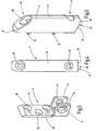
- FIG. 1 shows a corner bearing 1, which has a bearing block 2, a hinge pin 3 and a corner bearing bushing 4.
- the hinge pin 3 is pivotally mounted on the bearing block 2 by means of a horizontal bearing pin 5.
- the FIG. 2 shows the representation of FIG. 1 from a different perspective.
- the FIG. 3 It has a base plate 6, from which two mutually spaced flanges 7, 8 are bent, the receiving openings 9 for the bearing pin 5 have.
- the base plate 6 is provided with mounting holes 10 for corresponding fastening screws, with which the bearing block 2 can be fastened to a window frame of a window, not shown, a door or the like, not shown.
- the corner bearing bush 4 has a planar mounting surface 11 from which at least two fixing projections 12 originate.
- the mounting surface 11 is penetrated by two mounting holes 13 to the Ecklagerbuchse in the from FIGS. 4 and 5 arising upright position on a wing of a window, a door or the like.
- the Fixiervorsprünge 12 engage in corresponding recesses of the wing and stabilize the seat.
- the corner bearing bushing 4 is formed substantially as a hollow body 14 and has on its underside 15 one of the FIGS. 4 and 5 not directly protruding insertion opening 16 of an inner channel 17, the upper end substantially is closed, namely only a small control opening 18 has.
- FIG. 6 shows the frame-side element of the corner bearing 1, with bracket 2, and it with bearing pin 5 pivotable about a horizontal axis hinge pin 3.
- the hinged to the bearing block 2 fixed end 19 of the hinge pin 3 is located in the window, a door or the like trap below and the free end 20 of the hinge pin 3 above.
- the wing provided with corner bearing bush 4 (not shown) is supplied to the frame-side device of the corner bearing 1, that the free end 20 in the insertion opening 16 of Corner bearing bushing 4 enters and then the majority of the hinge pin 3 is inserted into the inner channel 17.
- the wing is now rotatable about the longitudinal axis of the hinge pin 3 and can - in the case of a provided tilting opening - are tilted about the horizontal axis of the bearing pin 5.
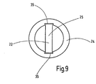
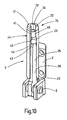
- FIG. 8 The partially cut view of the FIG. 8 showing a not inventive embodiment of the corner bearing, it can be seen that the hinge pin 3 composed of three individual parts. These are an inner pin 22, a screw stop 23 and a pin sleeve 24.
- the inner pin 22 is formed as a square pin 25 in that it is punched out as a sheet metal stamping 26 from a correspondingly thick sheet metal.
- the free end portion 27 of the inner bolt 22 has a smaller width dimension, such that on him the sleeve-like Screw stop 23 is screwed.
- the screw stop 23 in its interior a self-tapping internal thread 28.
- the screw stop 23 is screwed onto the free end region 27 of the square bolt 25, the free end region 27 is provided with an external thread 29 by the self-tapping internal thread 28.
- the screw stop 23 can be displaced axially back and forth by screwing movement, with the result that it makes the length of the overall structure adjustable by virtue of its property of forming an inner bolt extension 30.
- the pin sleeve 24 is formed, which is cup-shaped and therefore axially supported on the screw stop 23, so by rotation of the screw stop 23, the axial position of the pin sleeve 24 can be changed.
- the bolt sleeve 24 has a circular cylindrical outer contour.
- the bolt sleeve 24 has a rotary tool passage opening 32 on its end face 21, and that the screw stop 23 has a rotary tool coupling element 34, for example in the form of an inner bus, on its upper end face 33. If - with plugged pin sleeve 24 - a raising or lowering of the end face 21 of the hinge pin 3 done, it is only necessary that a fitter Allen key into the rotary tool passage opening 32 and inserts the Allen key into the rotary tool coupling element 34. By means of the Allen key twisting the screw stop can make the desired setting.
- the arrangement is such that the bolt sleeve 24 in its hollow interior preferably has two diametrically opposed mecanicalveriana 35 which are formed like a groove, and receive the square bolt 25, whereby the pin sleeve 24 is held against rotation on the inner pin 22.
- the pin sleeve 24 is made of plastic.
- FIG. 10 shows a further embodiment of the invention, wherein all embodiments of all other figures - except for FIG. 8 - Also apply accordingly for this further embodiment.
- the screw stop 23 has a self-tapping external thread 40 which is screwed into a constriction 41 in the interior 43 of the pin sleeve 24.
- the inner pin 22 does not engage - as in the embodiment of FIG. 8 - In the screw stop 23, but its free end 43 is supported - in the axial direction - on an end face 44 of the screw 23 from.
- the screw stop 23 can be displaced axially in the axial direction by twisting in the pin sleeve 24, whereby the support of the screw stop 23 on the inner pin 22 results in a corresponding axial position of the pin sleeve 24 relative to Inner bolt 22 sets.
Description
- Die Erfindung betrifft ein Ecklager für ein Fenster, eine Tür oder dergleichen, mit einem Lagerbock und einem am Lagerbock befestigten Gelenkbolzen. Derartige Ecklager befinden sich an der Bandseite von Fenstern, Türen oder dergleichen im unteren Bereich, das heißt, der entsprechende Fensterflügel, Türflügel-oder dergleichen stützt sich auf dem Ecklager ab, wobei das Ecklager bevorzugt ein Drehöffnen und/oder ein Kippöffnen des Flügels ermöglicht.
- Die
DE 2541263 beschreibt die Merkmale des Oberbegriffs des Anspruchs 1. - Die
FR 2892443 - Der Erfindung liegt die Aufgabe zugrunde, ein einfach aufgebautes, kostengünstiges Ecklager mit hoher Funktionalität zur Verfügung zu stellen.
- Diese Aufgabe wird durch die Merkmale des Anspruchs 1 gelöst. Der Gelenkbolzen weist einen Innenbolzen auf, der am Lagerbock befestigt ist und der mit einem Schraubanschlag zusammenwirkt, wobei Schraubanschlag und Innenbolzen von einer Bolzenhülse überfangen werden. Der Gelenkbolzen setzt sich demzufolge aus dem Innenbolzen, dem Schraubanschlag und die Bolzenhülse zusammen. Der Innenbolzen ist am Lagerbock befestigt, wobei der Lagerbock an einem Blendrahmen des Fensters, der Tür oder dergleichen befestigt wird. Der zugehörige Flügel des Fensters, der Tür oder dergleichen übergreift mit einer zum Ecklager gehörenden Ecklagerbuchse den Gelenkbolzen und ist dadurch zum Beispiel drehgelenkig und/oder kippgelenkig am Blendrahmen abgestützt gehalten. Um die Kippöffnungsstellung herbeizuführen, muss der Gelenkbolzen um eine horizontale Achse schwenkbeweglich mit dem Lagerbock verbunden sein. Die Besonderheit ist, dass der Schraubanschlag in Richtung der Längserstreckung des Gelenkbolzens durch Schraubbewegung axial verstellt werden kann, mit der Folge, dass die sich an dem Schraubanschlag abstützende Bolzenhülse entsprechend axial verlagert wird. Dies hat zur Folge, dass sich hierdurch die Position der Ecklagerbuchse relativ zum Lagerbock bezüglich der Längserstreckung des Gelenkbolzens axial verstellen lässt, sodass eine Positionseinstellung des Flügels relativ zum Blendrahmen durchgeführt werden kann. Demzufolge ergibt sich eine leicht realisierbare Flügeljustiermöglichkeit, um eine gute Gangbarkeit und ein sauberes Schließen des Fensters, der Tür oder dergleichen zu ermöglichen.
- Der Schraubanschlag ist in das Innere der Bolzenhülse eingeschraubt und statzt sich am freien Ende des Innenbolzens ab. Der Schraubanschlag befindet sich vorzugsweise tief im Innern der Bolzenhülse, wobei er dort durch Verdrehen axial, also in Richtung der Längserstreckung der Bolzenhülse, verlagert werden kann. Der in das Innere der Bolzenhülse eingreifende Innenbolzen stützt sich mit seinem freien Ende an dem Schraubanschlag ab, sodass die Einschraubtiefe des Schraubanschlags in die Bolzenhülse ihre axiale Position relativ zum Innenbolzen bestimmt.
- Nach einer Weiterbildung der Erfindung ist vorgesehen, dass der Schraubanschlag eine Innenbolzenverlängerung bildet. Hierzu ist vorzugsweise vorgesehen, dass der Schraubanschlag an dem freien Ende des Innenbolzens, also dem der Befestigung am Lagerbock dienenden Ende des Innenbolzens abgelegenen Ende, axial verstellbar angeordnet ist. Ein Herausschrauben des Schraubanschlags führt zu einer Innenbolzenverlängerung, ein Hineinschrauben des Schraubanschlags zu einer Innenbolzenverkürzung, mit der Folge, dass eine entsprechende Axialverlagerung der Bolzenhülse erfolgt. Da der Schraubanschlag in das Innere der Bolzenhülse eingeschraubt ist und sich am freien Ende des Innenbolzens abstützt, bildet der Schraubanschlag quasi eine Innenbolzenverlängerung, wobei diese beiden Teile jedoch nicht miteinander verbunden sind, sondern nur in axialer Richtung aneinanderliegen.
- Nach einer Weiterbildung der Erfindung ist vorgesehen, dass der Innenbolzen ein Vierkantbolzen ist. Da der Innenbolzen von der kreiszylindrischen Bolzenhülse überfangen wird, kann seine Querschnittsform von der Kreiszylinderform abweichen, da die Bolzenhülsenkontur für die Bandfunktion (Drehtiffnen) verantwortlich ist. Die Fertigung des Innenbolzens als Vierkantbolzen ist besonders einfach, da der Innenbolzen als Stanzteil, insbesondere Blechstanzteil, ausgebildet ist. Es ist dann nur erforderlich, ihn aus einem entsprechenden Blech auszustanzen; weitergehende Bearbeitungsschritte sind nicht erforderlich.
- Der Schraubanschlag ist bevorzugt zumindest bereichsweise hülsenartig ausgebildet. Seine hülsenartige Struktur übergreift vorzugsweise einen Bereich des Innenbolzens, das heißt, dieser Bereich wird innerhalb eines Hülseninnenraums des Schraubenanschlags aufgenommen.
- Es ist vorzugsweise vorgesehen, dass der Schraubanschlag ein Außengewinde aufweist, insbesondere ein selbstschneidendes Außengewinde, das in dass Innere der Bolzenhülse, vorzugsweise in eine Engstelle des Inneren der Bolzenhülse, eingeschraubt ist. Die Anordnung kann daher vorzugsweise derart getroffen sein, dass der mit vorzugsweise selbstschneidendem Außengewinde versehene Schraubanschlag in eine entsprechend tiefe Axialposition in das Innere der Bolzenhülse eingebracht ist und sich dort durch entsprechendes Verdrehen aufgrund seines zur Bolzenhülse bestehenden, vorzugsweise selbstgeschnittenen Gewindeeingriffs verdrehen und damit axial verlagern lässt. Damit lässt sich der Schraubanschlag relativ zur Längserstreckung der Bolzenhülse verstellen. Da sich das freie Ende des Innenbolzens an dem Schraubanschlag abstützt, führt ein Verdrehen des Schraubanschlags zu einer Axialverlagerung der Bolzenhülse relativ zum Innenbolzen, das heißt, die Bolzenhülsenposition lässt sich entsprechend einstellen.
- Die Bolzenhülse kann bevorzugt topfartig ausgebildet sein. Sie wird über den mit Schraubanschlag versehenen Innenbolzen gestülpt. Alternativ nimmt die Bolzenhülse den Schraubanschlag auf und wird dann über den Innenbolzen gestülpt. Bevorzugt besteht die Bolzenhülse aus Kunststoff. Um zu verhindern, dass sich die Bolzenhülse bei einer Drehöffnung des Flügels, des Fensters, der Tür oder dergleichen relativ zum Innenbolzen verdreht, kann sie in ihrem Inneren mit mindestens einer Innenaxialvertiefung versehen sein, in die der Vierkantbolzen beim Aufschieben der Bolzenhülse auf diesen drehfest eingreift.
- Die Bolzenhülse kann bevorzugt kopfseitig eine Drehwerkzeugdurchtrittsöffnung aufweisen. Ferner ist insbesondere vorgesehen, dass der Schraubanschlag ein Drehwerkzeugkupplungselement aufweist. Mit einem entsprechenden Werkzeug, beispielsweise einem Mehrkantwerkzeug, insbesondere Sechskantwerkzeug, zum Beispiel Inbusschlüssel, lässt sich bei fertig montiertem Gelenkbolzen eine axiale Verlängerung beziehungsweise Verkürzung dadurch bewirken, dass der Inbusschlüssel durch die kopfseitige Drehwerkzeugdurchtrittsöffnung der Bolzenhülse gesteckt und in das Drehwerkzeugkupplungselement des Schraubanschlags eingesteckt wird. Wird nun der Inbusschlüssel verdreht, so dreht sich der Schraubanschlag mit und verschiebt dabei die Bolzenhülse axial auf dem Innenbolzen.
- Schließlich ist es vorteilhaft, wenn der Durchmesser des Schraubanschlags derart bemessen ist, dass er nicht in die Innenaxialvertiefung der Bolzenhülse eingreift. Hierdurch ist die erwähnte, mittels des Inbusschlüssels mögliche Drehverstellung der Bolzenhülse bei fertig montiertem Gelenkbolzen möglich. Die dem Flügel des Fensters, der Tür oder dergleichen zugeordnete Ecklagerbuchse kann ebenfalls eine Durchgriffsöffnung für das Drehwerkzeug aufweisen, sodass es durch diese Durchgriffsöffnung und durch die Drehwerkzeugdurchtrittsöffnung der Bolzenhülse zum Eingriff in das Drehwerkzeugkupplungselement des Schraubanschlags gesteckt werden kann.
- Die Zeichnungen veranschaulichen die Erfindung anhand eines Ausführungsbeispiels, und zwar zeigt:
- Figur 1
- eine perspektivische Ansicht eines kompletten Ecklagers,
- Figur 2
- eine Darstellung gemäß
Figur 1 , jedoch aus einer anderen Perspektive, - Figur 3
- ein Lagerbock des Ecklagers,
- Figuren 4 und 5
- eine Ecklagerbuchse des Ecklagers,
- Figur 6
- eine Draufsicht auf das Ecklager ohne Ecklagerbuchse,
- Figur 7
- eine perspektivische Ansicht entsprechend der Darstellung der
Figur 6 , - Figur 8
- eine der
Figuren 6 beziehungsweise 7 entsprechende Darstellung, jedoch mit aufgeschnittener Bolzenhülse eines nicht erfinderischen Ausführungsbeispiels eines Ecklagers, - Figur 9
- ein schematischer Querschnitt durch das Ecklager im Bereich des Gelenkbolzens und
- Figur 10
- eine der
Figur 8 entsprechende Darstellung eines erfindungsgemäßen Ausführungsbeispiels. - Die
Figur 1 zeigt ein Ecklager 1, das einen Lagerbock 2, einen Gelenkbolzen 3 und eine Ecklagerbuchse 4 aufweist. Der Gelenkbolzen 3 ist mittels eines horizontalen Lagerbolzens 5 schwenkbar am Lagerbock 2 befestigt. DieFigur 2 zeigt die Darstellung derFigur 1 aus einer anderen Perspektive. - Die
Figur 3 zeigt den Lagerbock 2. Er weist eine Grundplatte 6 auf, von der zwei mit Abstand zueinander stehende Flansche 7, 8 abgebogen sind, die Aufnahmeöffnungen 9 für den Lagerbolzen 5 aufweisen. Die Grundplatte 6 ist mit Befestigungslöchern 10 für entsprechende Befestigungsschrauben versehen, mit denen der Lagerbock 2 an einen Blendrahmen eines nicht dargestellten Fensters, einer nicht dargestellten Tür oder dergleichen befestigbar ist. - Gemäß der
Figuren 4 und 5 weist die Ecklagerbuchse 4 eine ebene Montagefläche 11 auf, von der mindestens zwei Fixiervorsprünge 12 ausgehen. Die Montagefläche 11 wird von zwei Befestigungslöchern 13 durchsetzt, um die Ecklagerbuchse in der aus denFiguren 4 und 5 hervorgehenden, aufrechten Stellung an einem Flügel eines Fensters, einer Tür oder dergleichen zu befestigen. Die Fixiervorsprünge 12 greifen in entsprechende Vertiefungen des Flügels ein und stabilisieren den Sitz. Die Ecklagerbuchse 4 ist im Wesentlichen als Hohlkörper 14 ausgebildet und besitzt an ihrer Unterseite 15 eine aus denFiguren 4 und 5 nicht direkt hervorgehende Einschuböffnung 16 eines Innenkanals 17, dessen oberes Ende im Wesentlichen verschlossen ist, nämlich nur eine kleine Kontrollöffnung 18 aufweist. - Die
Figur 6 zeigt das blendrahmenseitige Element des Ecklagers 1, mit Lagerbock 2, und daran mit Lagerbolzen 5 um eine horizontale Achse verschwenkbaren Gelenkbolzen 3. Das gelenkig am Lagerbock 2 befestigte Ende 19 des Gelenkbolzens 3 befindet sich im am Fenster, einer Tür oder dergleichen eingesetzten Falle unten und das freie Ende 20 des Gelenkbolzens 3 oben. Um nun das Ecklager 1 zu vervollständigen und einen Flügel des Fensters, der Tür oder dergleichen zu halten, wird der mit Ecklagerbuchse 4 versehene Flügel (nicht dargestellt) derart der blendrahmenseitigen Einrichtung des Ecklagers 1 zugeführt, dass das freie Ende 20 in die Einschuböffnung 16 der Ecklagerbuchse 4 eintritt und dann der größte Teil des Gelenkbolzens 3 in den Innenkanal 17 eingeschoben. Eine obere Stirnfläche 21 des Gelenkbolzens 3 stößt gegen das obere, im Wesentlichen geschlossene Ende des Innenkanals 17, wodurch diese Einsetzbewegung begrenzt wird. Der Flügel ist nunmehr um die Längsachse des Gelenkbolzens 3 drehöffenbar und kann - im Falle einer vorgesehenen Kippöffnung - auch um die horizontale Achse des Lagerbolzens 5 gekippt werden. - Der teilweise aufgeschnittenen Darstellung der
Figur 8 , die ein nicht erfindungsgemäßes Ausführungsbeispiel des Ecklagers zeigt, ist entnehmbar, dass sich der Gelenkbolzen 3 aus drei Einzelteilen zusammensetzt. Es handelt sich dabei um einen Innenbolzen 22, einen Schraubanschlag 23 und eine Bolzenhülse 24. Der Innenbolzen 22 ist als Vierkantbolzen 25 dadurch ausgebildet, dass er als Blechstanzteil 26 aus einem entsprechend dicken Blech ausgestanzt ist. Der freie Endbereich 27 des Innenbolzens 22 weist eine geringere Breitenabmessung auf, derart, dass auf ihn der hülsenartige Schraubanschlag 23 aufgeschraubt ist. Hierzu weist der Schraubanschlag 23 in seinem Innern ein selbstschneidendes Innengewinde 28 auf. Wird der Schraubanschlag 23 auf den freien Endbereich 27 des Vierkantbolzens 25 aufgeschraubt, so wird der freie Endbereich 27 durch das selbstschneidende Innengewinde 28 mit einem Außengewinde 29 versehen. Demzufolge kann der Schraubanschlag 23 durch Schraubbewegung axial hin- beziehungsweise herverlagert werden, mit der Folge, dass er durch seine Eigenschaft, eine Innenbolzenverlängerung 30 zu bilden, die Länge des Gesamtgebildes einstellbar macht. Wird nun - wie aus denFiguren 6 bis 8 ersichtlich - über den Innenbolzen 22 und seine durch den Schraubanschlag 23 gebildete Innenbolzenverlängerung 30 die Bolzenhülse 24 gestülpt, die topfförmig ausgebildet ist und sich daher an dem Schraubanschlag 23 axial abstützt, so kann durch Verdrehung des Schraubanschlags 23 die axiale Position der Bolzenhülse 24 verändert werden. Dies wiederum hat zur Folge, dass die zum Gelenkbolzen 3 gehörende Bolzenhülse 24 die Höhenposition der auf sie aufgeschobenen Ecklagerbuchse 4 und damit die Flügelposition des Fensters, der Tür oder dergleichen bestimmt. Aus alledem wird deutlich, dass durch Verdrehen des Schraubanschlags 23 eine Flügeljustierung durchgeführt werden kann. Die Bolzenhülse 24 besitzt eine kreiszylindrische Außenkontur. - Insbesondere kann vorgesehen sein, dass die Bolzenhülse 24 an ihrer Stirnfläche 21 eine Drehwerkzeugdurchtrittsöffnung 32 aufweist und dass der Schraubanschlag 23 an seiner oberen Stirnseite 33 ein Drehwerkzeugkupplungselement 34, zum Beispiel in Form eines Inneninbus, aufweist. Soll - bei aufgesteckter Bolzenhülse 24 - ein Anheben oder Absenken der Stirnfläche 21 des Gelenkbolzens 3 erfolgen, so ist es lediglich erforderlich, dass ein Monteur einen Inbusschlüssel in die Drehwerkzeugdurchtrittsöffnung 32 einführt und den Inbusschlüssel in das Drehwerkzeugkupplungselement 34 einführt. Durch mittels des Inbusschlüssels erfolgendes Verdrehen des Schraubanschlags lässt sich die gewünschte Einstellung vornehmen.
- Gemäß
Figur 9 ist die Anordnung derart getroffen, dass die Bolzenhülse 24 in ihrem hohlen Inneren vorzugsweise zwei diametral einander gegenüberliegende Innenaxialvertiefungen 35 aufweist, die nutartig ausgebildet sind, und die den Vierkantbolzen 25 aufnehmen, wodurch die Bolzenhülse 24 verdrehsicher auf dem Innenbolzen 22 gehalten ist. Insbesondere kann vorgesehen sein, dass die Bolzenhülse 24 aus Kunststoff besteht. - Die
Figur 10 zeigt ein weiteres Ausführungsbeispiel der Erfindung, wobei sämtliche Ausführungen aller übrigen Figuren - bis aufFigur 8 - ebenfalls für dieses weitere Ausführungsbeispiel entsprechend gelten. Alternativ zum Ausführungsbeispiel derFigur 8 ist vorgesehen, dass der Schraubanschlag 23 ein selbstschneidendes Außengewinde 40 aufweist, das in eine Engstelle 41 im Innern 43 der Bolzenhülse 24 eingeschraubt ist. Der Innenbolzen 22 greift nicht - wie beim Ausführungsbeispiel derFigur 8 - in den Schraubanschlag 23 ein, sondern sein freies Ende 43 stützt sich - in axialer Richtung - an einer Stirnfläche 44 des Schraubanschlags 23 ab. Mittels des entsprechenden Drehwerkzeugs, beispielsweise des erwähnten Inbusschlüssels, lässt sich der Schraubanschlag 23 in axialer Richtung durch Verdrehen in der Bolzenhülse 24 relativ zu dieser axial verlagern, wodurch sich durch die Abstützung des Schraubanschlags 23 an dem Innenbolzen 22 eine entsprechende Axialstellung der Bolzenhülse 24 relativ zum Innenbolzen 22 einstellt. Im Übrigen gelten die zu dem anderen Ausführungsbeispiel vorhandenen Erläuterungen entsprechend für das Ausführungsbeispiel derFigur 10 .
Claims (11)
- Ecklager (1) für ein Fenster, eine Tür oder dergleichen, mit einem Lagerbock (2) und einem am Lagerbock (2) befestigten Gelenkbolzen (3), der einen Innenbolzen (22) und eine Bolzenhülse (24) aufweist, der am Lagerbock (2) befestigt ist, dadurch gekennzeichnet, dass der Innenbolzen (22) mit einem, einer axialen Verlagerung der Bolzenhülse (24) dienenden Schraubanschlag (23) zusammenwirkt, wobei Schraubanschlag (23) und Innenbolzen (22) von der Bolzenhülse (24) überfangen werden, wobei der Schraubanschlag (23) in das Innere der Bolzenhülse (24) eingeschraubt ist und sich am freien Ende des Innenbolzens (22) abstützt, und wobei der Innenbolzen (22) als Stanzteil, insbesondere als Blechstanzteil (26), ausgebildet ist.
- Ecklager nach Anspruch 1, dadurch gekennzeichnet, dass der Schraubanschlag (23) im Innern der Bolzenhülse (24) axial verstellbar angeordnet ist.
- Ecklager nach einem der vorhergehenden Ansprüche, dadurch gekennzeichnet, dass der Innenbolzen (22) ein Vierkantbolzen (25) ist.
- Ecklager nach einem der vorhergehenden Ansprüche, dadurch gekennzeichnet, dass der Schraubanschlag (23) zumindest bereichsweise hülsenartig ausgebildet ist.
- Ecklager nach einem der vorhergehenden Ansprüche, dadurch gekennzeichnet, dass der Schraubanschlag (23) ein Außengewinde (40) aufweist, insbesondere ein selbstschneidendes Außengewinde, das in das Innere (42) der Bolzenhülse (24), vorzugsweise in eine Engstelle (41) des Inneren (42) der Bolzenhülse (24), eingeschraubt ist.
- Ecklager nach einem der vorhergehenden Ansprüche, dadurch gekennzeichnet, dass die Bolzenhülse (24) topfartig ausgebildet ist.
- Ecklager nach einem der vorhergehenden Ansprüche, dadurch gekennzeichnet, dass die Bolzenhülse (24) aus Kunststoff besteht.
- Ecklager nach einem der vorhergehenden Ansprüche, dadurch gekennzeichnet, dass die Bolzenhülse (24) mindestens eine Innenaxialvertiefung (35) für die verdrehfeste Aufnahme des Vierkantbolzens (25) aufweist.
- Ecklager nach einem der vorhergehenden Ansprüche, dadurch gekennzeichnet, dass die Bolzenhülse (24) kopfseitig eine Drehwerkzeugdurchtrittsöffnung (32) aufweist.
- Ecklager nach einem der vorhergehenden Ansprüche, dadurch gekennzeichnet, dass der Schraubanschlag (23) ein Drehwerkzeugkuppelelement (34) aufweist.
- Ecklager nach Anspruch 8 dadurch gekennzeichnet, dass der Durchmesser des Schraubanschlags (23) derart bemessen ist, dass er nicht in die Innenaxialvertiefung (35) der Bolzenhülse (24) eingreift.
Priority Applications (2)
| Application Number | Priority Date | Filing Date | Title |
|---|---|---|---|
| SI200831117T SI2245251T1 (sl) | 2008-01-15 | 2008-12-13 | Kotni leĺ˝aj za okno, vrata ali podobno |
| PL08870780T PL2245251T3 (pl) | 2008-01-15 | 2008-12-13 | Zawias narożny do okna, drzwi, albo temu podobnego elementu |
Applications Claiming Priority (2)
| Application Number | Priority Date | Filing Date | Title |
|---|---|---|---|
| DE102008004356A DE102008004356B4 (de) | 2008-01-15 | 2008-01-15 | Ecklager für ein Fenster, eine Tür oder dergleichen |
| PCT/EP2008/010625 WO2009089883A1 (de) | 2008-01-15 | 2008-12-13 | Ecklager für ein fenster, eine tür oder dergleichen |
Publications (2)
| Publication Number | Publication Date |
|---|---|
| EP2245251A1 EP2245251A1 (de) | 2010-11-03 |
| EP2245251B1 true EP2245251B1 (de) | 2013-09-11 |
Family
ID=40342984
Family Applications (1)
| Application Number | Title | Priority Date | Filing Date |
|---|---|---|---|
| EP08870780.7A Active EP2245251B1 (de) | 2008-01-15 | 2008-12-13 | Ecklager für ein fenster, eine tür oder dergleichen |
Country Status (9)
| Country | Link |
|---|---|
| EP (1) | EP2245251B1 (de) |
| CN (1) | CN101910536B (de) |
| DE (1) | DE102008004356B4 (de) |
| EA (1) | EA017972B1 (de) |
| ES (1) | ES2436784T3 (de) |
| PL (1) | PL2245251T3 (de) |
| SI (1) | SI2245251T1 (de) |
| UA (1) | UA101964C2 (de) |
| WO (1) | WO2009089883A1 (de) |
Cited By (1)
| Publication number | Priority date | Publication date | Assignee | Title |
|---|---|---|---|---|
| DE102015003931B3 (de) * | 2015-03-25 | 2015-11-12 | Siegenia-Aubi Kg | Gelenkbandanordnung |
Families Citing this family (4)
| Publication number | Priority date | Publication date | Assignee | Title |
|---|---|---|---|---|
| CN101906914B (zh) * | 2010-08-26 | 2013-04-17 | 宋武景 | 左右可调式塑钢窗合页 |
| JP2013209813A (ja) * | 2012-03-30 | 2013-10-10 | Lixil Corp | 軸受金具の取付構造及び内倒し兼用内開き窓 |
| EP2698492B1 (de) * | 2012-08-16 | 2018-10-10 | Roto Frank AG | Einstellbares ecklager für einen flügel eines fensters, einer tür oder dergleichen |
| CN103352620B (zh) * | 2013-07-08 | 2016-03-09 | 山东国强五金科技有限公司 | 制作塑钢内开上悬窗下铰链部件时其下铰链尺寸推算方法 |
Family Cites Families (12)
| Publication number | Priority date | Publication date | Assignee | Title |
|---|---|---|---|---|
| DE2541263C2 (de) * | 1975-09-16 | 1990-11-15 | Fa. Aug. Winkhaus, 4404 Telgte | Verstellbares Ecklager |
| DE7830496U1 (de) * | 1978-10-13 | 1979-01-25 | Siegenia-Frank Kg, 5900 Siegen | Fluegelgelenkband fuer fenster, tueren o.dgl. |
| DE3001070A1 (de) * | 1980-01-14 | 1981-07-23 | Siegenia-Frank Kg, 5900 Siegen | Eckgelenk fuer drehkippfenster, -tueren o.dgl. |
| DE3021178C2 (de) * | 1980-06-04 | 1985-10-17 | Fa. Aug. Winkhaus, 4404 Telgte | Ecklageranordnung eines Drehkippbeschlags an einem Fenster o.dgl. |
| DE3223625C2 (de) * | 1982-06-24 | 1986-02-13 | August Bilstein GmbH & Co KG, 5828 Ennepetal | Ecklager für Flügel von Fenstern, Türen od.dgl. |
| FR2629125A1 (fr) * | 1988-03-24 | 1989-09-29 | Ferco Int Usine Ferrures | Ferrure pour battant d'une porte, fenetre ou analogue s'ouvrant " a l'anglaise " |
| DE29602522U1 (de) * | 1996-02-14 | 1996-05-09 | Siegenia Frank Kg | Eckscharnier, insbesondere Drehkipp-Ecklager für Fenster und Türen o.dgl. |
| IT1309467B1 (it) * | 1999-08-04 | 2002-01-23 | Euroinvest S R L | Cerniera per finestre del tipo apribili ad anta e a ribalta. |
| FR2808045B1 (fr) * | 2000-04-20 | 2002-07-12 | Ferco Int Usine Ferrures | Support d'angle pour porte, fenetre ou analogue |
| DE20317592U1 (de) * | 2003-11-13 | 2004-02-12 | Siegenia-Aubi Kg | Scharnierbeschlag für Dreh-Kipp-Fenster oder -Türen |
| DE102004013299A1 (de) * | 2004-03-18 | 2005-09-29 | Aug. Winkhaus Gmbh & Co. Kg | Ecklager für einen Dreh-Kipp-Beschlag |
| FR2892443B1 (fr) * | 2005-10-21 | 2009-02-13 | Tordo Belgrano Sa Ets | Gond d'articulation pour vantail |
-
2008
- 2008-01-15 DE DE102008004356A patent/DE102008004356B4/de not_active Expired - Fee Related
- 2008-12-13 ES ES08870780.7T patent/ES2436784T3/es active Active
- 2008-12-13 UA UAA201010049A patent/UA101964C2/ru unknown
- 2008-12-13 CN CN2008801247061A patent/CN101910536B/zh not_active Expired - Fee Related
- 2008-12-13 EA EA201070850A patent/EA017972B1/ru not_active IP Right Cessation
- 2008-12-13 EP EP08870780.7A patent/EP2245251B1/de active Active
- 2008-12-13 SI SI200831117T patent/SI2245251T1/sl unknown
- 2008-12-13 PL PL08870780T patent/PL2245251T3/pl unknown
- 2008-12-13 WO PCT/EP2008/010625 patent/WO2009089883A1/de active Application Filing
Cited By (2)
| Publication number | Priority date | Publication date | Assignee | Title |
|---|---|---|---|---|
| DE102015003931B3 (de) * | 2015-03-25 | 2015-11-12 | Siegenia-Aubi Kg | Gelenkbandanordnung |
| EP3073039A1 (de) | 2015-03-25 | 2016-09-28 | Siegenia-Aubi Kg | Gelenkbandanordnung |
Also Published As
| Publication number | Publication date |
|---|---|
| EA017972B1 (ru) | 2013-04-30 |
| UA101964C2 (ru) | 2013-05-27 |
| WO2009089883A8 (de) | 2009-09-17 |
| ES2436784T3 (es) | 2014-01-07 |
| WO2009089883A1 (de) | 2009-07-23 |
| EA201070850A1 (ru) | 2010-12-30 |
| SI2245251T1 (sl) | 2014-01-31 |
| DE102008004356A1 (de) | 2009-08-06 |
| EP2245251A1 (de) | 2010-11-03 |
| CN101910536B (zh) | 2013-10-02 |
| PL2245251T3 (pl) | 2014-02-28 |
| CN101910536A (zh) | 2010-12-08 |
| DE102008004356B4 (de) | 2011-06-01 |
Similar Documents
| Publication | Publication Date | Title |
|---|---|---|
| EP2245251B1 (de) | Ecklager für ein fenster, eine tür oder dergleichen | |
| EP1577476B1 (de) | Scharnier zur drehbaren Halterung einer Tür oder eines Fensters an einem Rahmen | |
| EP2245252B1 (de) | Einstellbares ecklager für einen flügel eines fensters, einer tür oder dergleichen | |
| EP1020154A2 (de) | Duschabtrennung | |
| DE102008049740B4 (de) | Höhenverstellbares Band | |
| EP2754813B1 (de) | Band, insbesondere für Kunststoff-Türen und -Fenster | |
| EP1017920B1 (de) | Beschlag zur drehlagerung eines fenster- oder türflügels | |
| EP1094183B1 (de) | Scharniereinrichtung | |
| EP2503084B1 (de) | Verstellbares Scharnierband | |
| DE102010047774B4 (de) | Türscharnier | |
| DE10110311C2 (de) | Scharnier mit Höhenverstellschraube | |
| DE3637077C1 (de) | Scharniergelenk fuer Fenster,Tueren od.dgl. | |
| EP1215357B1 (de) | Bandanordnung für Türen, Fenster und dergleichen | |
| EP0652345B1 (de) | Einstellbares Gelenkband für Türen oder Fenster | |
| DE10313961B4 (de) | Verstellbares Band, insbesondere für Dusch- und/oder Glastüren | |
| EP1781881A1 (de) | Montageplatte zur verstellbaren halterung von möbelscharnieren am korpus von möbelstücken | |
| WO2007087945A1 (de) | Bandanordnung zur scharniergelenkigen verbindung eines flügels einer tür, eines fensters oder dergleichen, an einem rahmen | |
| EP0487825B1 (de) | Verdeckt angeordneter Beschlag für Drehflügel, insb. für Dreh-Kipp-Flügel von Fenstern oder Türen | |
| WO2004085780A1 (de) | Band, insbesondere für dusch- und/oder glastüren | |
| EP1512817B1 (de) | Band für Türen, Fenster oder dergleichen | |
| DE202004004258U1 (de) | Scharnier und Duschabtrennung | |
| EP0704593B1 (de) | Dreh-Beschlag oder Dreh-Kipp-Beschlag von Fenster, Türen oder dergleichen mit verrastbarem Exzenterteil zum Einstellen einer horizontalen Falzluft und/oder eines Flügelanpressdrucks zwischen Festrahmen und/oder Flügelrahmen | |
| DE19829503B4 (de) | Gelenkrad, insbesondere für Glaspendeltüren | |
| WO2004038153A1 (de) | Beschlaganordnung für glastüren | |
| EP2157266B1 (de) | Scharnier für ein mit einer Tür versehenes Möbelstück |
Legal Events
| Date | Code | Title | Description |
|---|---|---|---|
| PUAI | Public reference made under article 153(3) epc to a published international application that has entered the european phase |
Free format text: ORIGINAL CODE: 0009012 |
|
| 17P | Request for examination filed |
Effective date: 20100816 |
|
| AK | Designated contracting states |
Kind code of ref document: A1 Designated state(s): AT BE BG CH CY CZ DE DK EE ES FI FR GB GR HR HU IE IS IT LI LT LU LV MC MT NL NO PL PT RO SE SI SK TR |
|
| AX | Request for extension of the european patent |
Extension state: AL BA MK RS |
|
| RAX | Requested extension states of the european patent have changed |
Extension state: RS Payment date: 20100816 Extension state: BA Payment date: 20100816 |
|
| 17Q | First examination report despatched |
Effective date: 20120208 |
|
| GRAP | Despatch of communication of intention to grant a patent |
Free format text: ORIGINAL CODE: EPIDOSNIGR1 |
|
| GRAP | Despatch of communication of intention to grant a patent |
Free format text: ORIGINAL CODE: EPIDOSNIGR1 |
|
| INTG | Intention to grant announced |
Effective date: 20130603 |
|
| GRAS | Grant fee paid |
Free format text: ORIGINAL CODE: EPIDOSNIGR3 |
|
| GRAA | (expected) grant |
Free format text: ORIGINAL CODE: 0009210 |
|
| AK | Designated contracting states |
Kind code of ref document: B1 Designated state(s): AT BE BG CH CY CZ DE DK EE ES FI FR GB GR HR HU IE IS IT LI LT LU LV MC MT NL NO PL PT RO SE SI SK TR |
|
| AX | Request for extension of the european patent |
Extension state: BA RS |
|
| REG | Reference to a national code |
Ref country code: GB Ref legal event code: FG4D Free format text: NOT ENGLISH |
|
| REG | Reference to a national code |
Ref country code: CH Ref legal event code: EP |
|
| REG | Reference to a national code |
Ref country code: AT Ref legal event code: REF Ref document number: 631748 Country of ref document: AT Kind code of ref document: T Effective date: 20130915 |
|
| REG | Reference to a national code |
Ref country code: IE Ref legal event code: FG4D Free format text: LANGUAGE OF EP DOCUMENT: GERMAN |
|
| REG | Reference to a national code |
Ref country code: DE Ref legal event code: R096 Ref document number: 502008010656 Country of ref document: DE Effective date: 20131107 |
|
| REG | Reference to a national code |
Ref country code: ES Ref legal event code: FG2A Ref document number: 2436784 Country of ref document: ES Kind code of ref document: T3 Effective date: 20140107 |
|
| PG25 | Lapsed in a contracting state [announced via postgrant information from national office to epo] |
Ref country code: SE Free format text: LAPSE BECAUSE OF FAILURE TO SUBMIT A TRANSLATION OF THE DESCRIPTION OR TO PAY THE FEE WITHIN THE PRESCRIBED TIME-LIMIT Effective date: 20130911 Ref country code: NO Free format text: LAPSE BECAUSE OF FAILURE TO SUBMIT A TRANSLATION OF THE DESCRIPTION OR TO PAY THE FEE WITHIN THE PRESCRIBED TIME-LIMIT Effective date: 20131211 Ref country code: LT Free format text: LAPSE BECAUSE OF FAILURE TO SUBMIT A TRANSLATION OF THE DESCRIPTION OR TO PAY THE FEE WITHIN THE PRESCRIBED TIME-LIMIT Effective date: 20130911 Ref country code: HR Free format text: LAPSE BECAUSE OF FAILURE TO SUBMIT A TRANSLATION OF THE DESCRIPTION OR TO PAY THE FEE WITHIN THE PRESCRIBED TIME-LIMIT Effective date: 20130911 Ref country code: CY Free format text: LAPSE BECAUSE OF FAILURE TO SUBMIT A TRANSLATION OF THE DESCRIPTION OR TO PAY THE FEE WITHIN THE PRESCRIBED TIME-LIMIT Effective date: 20130710 |
|
| PGFP | Annual fee paid to national office [announced via postgrant information from national office to epo] |
Ref country code: CZ Payment date: 20131122 Year of fee payment: 6 Ref country code: AT Payment date: 20131211 Year of fee payment: 6 |
|
| REG | Reference to a national code |
Ref country code: NL Ref legal event code: VDEP Effective date: 20130911 |
|
| REG | Reference to a national code |
Ref country code: LT Ref legal event code: MG4D |
|
| PG25 | Lapsed in a contracting state [announced via postgrant information from national office to epo] |
Ref country code: LV Free format text: LAPSE BECAUSE OF FAILURE TO SUBMIT A TRANSLATION OF THE DESCRIPTION OR TO PAY THE FEE WITHIN THE PRESCRIBED TIME-LIMIT Effective date: 20130911 Ref country code: FI Free format text: LAPSE BECAUSE OF FAILURE TO SUBMIT A TRANSLATION OF THE DESCRIPTION OR TO PAY THE FEE WITHIN THE PRESCRIBED TIME-LIMIT Effective date: 20130911 Ref country code: GR Free format text: LAPSE BECAUSE OF FAILURE TO SUBMIT A TRANSLATION OF THE DESCRIPTION OR TO PAY THE FEE WITHIN THE PRESCRIBED TIME-LIMIT Effective date: 20131212 |
|
| PGFP | Annual fee paid to national office [announced via postgrant information from national office to epo] |
Ref country code: ES Payment date: 20131220 Year of fee payment: 6 |
|
| REG | Reference to a national code |
Ref country code: PL Ref legal event code: T3 |
|
| PG25 | Lapsed in a contracting state [announced via postgrant information from national office to epo] |
Ref country code: CY Free format text: LAPSE BECAUSE OF FAILURE TO SUBMIT A TRANSLATION OF THE DESCRIPTION OR TO PAY THE FEE WITHIN THE PRESCRIBED TIME-LIMIT Effective date: 20130911 |
|
| PG25 | Lapsed in a contracting state [announced via postgrant information from national office to epo] |
Ref country code: RO Free format text: LAPSE BECAUSE OF FAILURE TO SUBMIT A TRANSLATION OF THE DESCRIPTION OR TO PAY THE FEE WITHIN THE PRESCRIBED TIME-LIMIT Effective date: 20130911 Ref country code: SK Free format text: LAPSE BECAUSE OF FAILURE TO SUBMIT A TRANSLATION OF THE DESCRIPTION OR TO PAY THE FEE WITHIN THE PRESCRIBED TIME-LIMIT Effective date: 20130911 Ref country code: EE Free format text: LAPSE BECAUSE OF FAILURE TO SUBMIT A TRANSLATION OF THE DESCRIPTION OR TO PAY THE FEE WITHIN THE PRESCRIBED TIME-LIMIT Effective date: 20130911 Ref country code: NL Free format text: LAPSE BECAUSE OF FAILURE TO SUBMIT A TRANSLATION OF THE DESCRIPTION OR TO PAY THE FEE WITHIN THE PRESCRIBED TIME-LIMIT Effective date: 20130911 Ref country code: IS Free format text: LAPSE BECAUSE OF FAILURE TO SUBMIT A TRANSLATION OF THE DESCRIPTION OR TO PAY THE FEE WITHIN THE PRESCRIBED TIME-LIMIT Effective date: 20140111 |
|
| PGFP | Annual fee paid to national office [announced via postgrant information from national office to epo] |
Ref country code: FR Payment date: 20131220 Year of fee payment: 6 Ref country code: SI Payment date: 20140228 Year of fee payment: 6 |
|
| REG | Reference to a national code |
Ref country code: DE Ref legal event code: R097 Ref document number: 502008010656 Country of ref document: DE |
|
| BERE | Be: lapsed |
Owner name: ROTO FRANK A.G. Effective date: 20131231 |
|
| PG25 | Lapsed in a contracting state [announced via postgrant information from national office to epo] |
Ref country code: PT Free format text: LAPSE BECAUSE OF FAILURE TO SUBMIT A TRANSLATION OF THE DESCRIPTION OR TO PAY THE FEE WITHIN THE PRESCRIBED TIME-LIMIT Effective date: 20140113 |
|
| PLBE | No opposition filed within time limit |
Free format text: ORIGINAL CODE: 0009261 |
|
| STAA | Information on the status of an ep patent application or granted ep patent |
Free format text: STATUS: NO OPPOSITION FILED WITHIN TIME LIMIT |
|
| REG | Reference to a national code |
Ref country code: CH Ref legal event code: PL |
|
| 26N | No opposition filed |
Effective date: 20140612 |
|
| GBPC | Gb: european patent ceased through non-payment of renewal fee |
Effective date: 20131213 |
|
| PG25 | Lapsed in a contracting state [announced via postgrant information from national office to epo] |
Ref country code: LU Free format text: LAPSE BECAUSE OF FAILURE TO SUBMIT A TRANSLATION OF THE DESCRIPTION OR TO PAY THE FEE WITHIN THE PRESCRIBED TIME-LIMIT Effective date: 20131213 Ref country code: IT Free format text: LAPSE BECAUSE OF FAILURE TO SUBMIT A TRANSLATION OF THE DESCRIPTION OR TO PAY THE FEE WITHIN THE PRESCRIBED TIME-LIMIT Effective date: 20130911 Ref country code: MC Free format text: LAPSE BECAUSE OF FAILURE TO SUBMIT A TRANSLATION OF THE DESCRIPTION OR TO PAY THE FEE WITHIN THE PRESCRIBED TIME-LIMIT Effective date: 20130911 |
|
| REG | Reference to a national code |
Ref country code: IE Ref legal event code: MM4A |
|
| REG | Reference to a national code |
Ref country code: DE Ref legal event code: R097 Ref document number: 502008010656 Country of ref document: DE Effective date: 20140612 |
|
| PG25 | Lapsed in a contracting state [announced via postgrant information from national office to epo] |
Ref country code: DK Free format text: LAPSE BECAUSE OF FAILURE TO SUBMIT A TRANSLATION OF THE DESCRIPTION OR TO PAY THE FEE WITHIN THE PRESCRIBED TIME-LIMIT Effective date: 20130911 |
|
| PGFP | Annual fee paid to national office [announced via postgrant information from national office to epo] |
Ref country code: PL Payment date: 20131125 Year of fee payment: 6 |
|
| PG25 | Lapsed in a contracting state [announced via postgrant information from national office to epo] |
Ref country code: BE Free format text: LAPSE BECAUSE OF NON-PAYMENT OF DUE FEES Effective date: 20131231 Ref country code: CH Free format text: LAPSE BECAUSE OF NON-PAYMENT OF DUE FEES Effective date: 20131231 Ref country code: LI Free format text: LAPSE BECAUSE OF NON-PAYMENT OF DUE FEES Effective date: 20131231 Ref country code: IE Free format text: LAPSE BECAUSE OF NON-PAYMENT OF DUE FEES Effective date: 20131213 |
|
| PG25 | Lapsed in a contracting state [announced via postgrant information from national office to epo] |
Ref country code: GB Free format text: LAPSE BECAUSE OF NON-PAYMENT OF DUE FEES Effective date: 20131213 |
|
| PG25 | Lapsed in a contracting state [announced via postgrant information from national office to epo] |
Ref country code: CZ Free format text: LAPSE BECAUSE OF NON-PAYMENT OF DUE FEES Effective date: 20141213 Ref country code: HU Free format text: LAPSE BECAUSE OF FAILURE TO SUBMIT A TRANSLATION OF THE DESCRIPTION OR TO PAY THE FEE WITHIN THE PRESCRIBED TIME-LIMIT; INVALID AB INITIO Effective date: 20081213 Ref country code: BG Free format text: LAPSE BECAUSE OF FAILURE TO SUBMIT A TRANSLATION OF THE DESCRIPTION OR TO PAY THE FEE WITHIN THE PRESCRIBED TIME-LIMIT Effective date: 20130911 |
|
| REG | Reference to a national code |
Ref country code: AT Ref legal event code: MM01 Ref document number: 631748 Country of ref document: AT Kind code of ref document: T Effective date: 20141213 |
|
| PG25 | Lapsed in a contracting state [announced via postgrant information from national office to epo] |
Ref country code: MT Free format text: LAPSE BECAUSE OF FAILURE TO SUBMIT A TRANSLATION OF THE DESCRIPTION OR TO PAY THE FEE WITHIN THE PRESCRIBED TIME-LIMIT Effective date: 20130911 |
|
| REG | Reference to a national code |
Ref country code: FR Ref legal event code: ST Effective date: 20150831 |
|
| REG | Reference to a national code |
Ref country code: SI Ref legal event code: KO00 Effective date: 20150826 |
|
| PG25 | Lapsed in a contracting state [announced via postgrant information from national office to epo] |
Ref country code: SI Free format text: LAPSE BECAUSE OF NON-PAYMENT OF DUE FEES Effective date: 20141214 Ref country code: AT Free format text: LAPSE BECAUSE OF NON-PAYMENT OF DUE FEES Effective date: 20141213 Ref country code: FR Free format text: LAPSE BECAUSE OF NON-PAYMENT OF DUE FEES Effective date: 20141231 |
|
| REG | Reference to a national code |
Ref country code: ES Ref legal event code: FD2A Effective date: 20160128 |
|
| PG25 | Lapsed in a contracting state [announced via postgrant information from national office to epo] |
Ref country code: ES Free format text: LAPSE BECAUSE OF NON-PAYMENT OF DUE FEES Effective date: 20141214 |
|
| PG25 | Lapsed in a contracting state [announced via postgrant information from national office to epo] |
Ref country code: PL Free format text: LAPSE BECAUSE OF NON-PAYMENT OF DUE FEES Effective date: 20141213 |
|
| PGFP | Annual fee paid to national office [announced via postgrant information from national office to epo] |
Ref country code: DE Payment date: 20191211 Year of fee payment: 12 |
|
| PGFP | Annual fee paid to national office [announced via postgrant information from national office to epo] |
Ref country code: TR Payment date: 20191209 Year of fee payment: 12 |
|
| REG | Reference to a national code |
Ref country code: DE Ref legal event code: R119 Ref document number: 502008010656 Country of ref document: DE |
|
| PG25 | Lapsed in a contracting state [announced via postgrant information from national office to epo] |
Ref country code: DE Free format text: LAPSE BECAUSE OF NON-PAYMENT OF DUE FEES Effective date: 20210701 |
|
| PG25 | Lapsed in a contracting state [announced via postgrant information from national office to epo] |
Ref country code: TR Free format text: LAPSE BECAUSE OF NON-PAYMENT OF DUE FEES Effective date: 20201213 |