EP2243266B1 - Vorrichtung und verfahren zur schätzung von i/q-ungleichgewichtsparametern in einem ofdm-empfänger - Google Patents
Vorrichtung und verfahren zur schätzung von i/q-ungleichgewichtsparametern in einem ofdm-empfänger Download PDFInfo
- Publication number
- EP2243266B1 EP2243266B1 EP09712702.1A EP09712702A EP2243266B1 EP 2243266 B1 EP2243266 B1 EP 2243266B1 EP 09712702 A EP09712702 A EP 09712702A EP 2243266 B1 EP2243266 B1 EP 2243266B1
- Authority
- EP
- European Patent Office
- Prior art keywords
- phase difference
- estimating
- unbalance
- difference
- pilot tones
- Prior art date
- Legal status (The legal status is an assumption and is not a legal conclusion. Google has not performed a legal analysis and makes no representation as to the accuracy of the status listed.)
- Not-in-force
Links
Images

Classifications
-
- H—ELECTRICITY
- H04—ELECTRIC COMMUNICATION TECHNIQUE
- H04L—TRANSMISSION OF DIGITAL INFORMATION, e.g. TELEGRAPHIC COMMUNICATION
- H04L27/00—Modulated-carrier systems
- H04L27/26—Systems using multi-frequency codes
- H04L27/2601—Multicarrier modulation systems
- H04L27/2647—Arrangements specific to the receiver only
- H04L27/2655—Synchronisation arrangements
- H04L27/2668—Details of algorithms
- H04L27/2673—Details of algorithms characterised by synchronisation parameters
- H04L27/2675—Pilot or known symbols
-
- H—ELECTRICITY
- H04—ELECTRIC COMMUNICATION TECHNIQUE
- H04L—TRANSMISSION OF DIGITAL INFORMATION, e.g. TELEGRAPHIC COMMUNICATION
- H04L27/00—Modulated-carrier systems
- H04L27/26—Systems using multi-frequency codes
- H04L27/2601—Multicarrier modulation systems
- H04L27/2647—Arrangements specific to the receiver only
-
- H—ELECTRICITY
- H04—ELECTRIC COMMUNICATION TECHNIQUE
- H04L—TRANSMISSION OF DIGITAL INFORMATION, e.g. TELEGRAPHIC COMMUNICATION
- H04L27/00—Modulated-carrier systems
- H04L27/26—Systems using multi-frequency codes
- H04L27/2601—Multicarrier modulation systems
- H04L27/2602—Signal structure
- H04L27/261—Details of reference signals
- H04L27/2613—Structure of the reference signals
-
- H—ELECTRICITY
- H04—ELECTRIC COMMUNICATION TECHNIQUE
- H04L—TRANSMISSION OF DIGITAL INFORMATION, e.g. TELEGRAPHIC COMMUNICATION
- H04L27/00—Modulated-carrier systems
- H04L27/26—Systems using multi-frequency codes
- H04L27/2601—Multicarrier modulation systems
- H04L27/2647—Arrangements specific to the receiver only
- H04L27/2655—Synchronisation arrangements
- H04L27/2666—Acquisition of further OFDM parameters, e.g. bandwidth, subcarrier spacing, or guard interval length
-
- H—ELECTRICITY
- H04—ELECTRIC COMMUNICATION TECHNIQUE
- H04L—TRANSMISSION OF DIGITAL INFORMATION, e.g. TELEGRAPHIC COMMUNICATION
- H04L27/00—Modulated-carrier systems
- H04L27/26—Systems using multi-frequency codes
- H04L27/2601—Multicarrier modulation systems
- H04L27/2647—Arrangements specific to the receiver only
- H04L27/2655—Synchronisation arrangements
- H04L27/2689—Link with other circuits, i.e. special connections between synchronisation arrangements and other circuits for achieving synchronisation
- H04L27/2695—Link with other circuits, i.e. special connections between synchronisation arrangements and other circuits for achieving synchronisation with channel estimation, e.g. determination of delay spread, derivative or peak tracking
-
- H—ELECTRICITY
- H04—ELECTRIC COMMUNICATION TECHNIQUE
- H04L—TRANSMISSION OF DIGITAL INFORMATION, e.g. TELEGRAPHIC COMMUNICATION
- H04L27/00—Modulated-carrier systems
- H04L27/32—Carrier systems characterised by combinations of two or more of the types covered by groups H04L27/02, H04L27/10, H04L27/18 or H04L27/26
- H04L27/34—Amplitude- and phase-modulated carrier systems, e.g. quadrature-amplitude modulated carrier systems
- H04L27/38—Demodulator circuits; Receiver circuits
- H04L27/3845—Demodulator circuits; Receiver circuits using non - coherent demodulation, i.e. not using a phase synchronous carrier
- H04L27/3854—Demodulator circuits; Receiver circuits using non - coherent demodulation, i.e. not using a phase synchronous carrier using a non - coherent carrier, including systems with baseband correction for phase or frequency offset
- H04L27/3863—Compensation for quadrature error in the received signal
-
- H—ELECTRICITY
- H04—ELECTRIC COMMUNICATION TECHNIQUE
- H04L—TRANSMISSION OF DIGITAL INFORMATION, e.g. TELEGRAPHIC COMMUNICATION
- H04L5/00—Arrangements affording multiple use of the transmission path
- H04L5/003—Arrangements for allocating sub-channels of the transmission path
- H04L5/0048—Allocation of pilot signals, i.e. of signals known to the receiver
Definitions
- the present invention relates to an apparatus and a method for estimating I/Q unbalance parameters in an Orthogonal Frequency Division Multiplexing (OFDM) receiver. More particularly, the present invention relates to an apparatus and a method for estimating I/Q unbalance parameters using a pilot tone of a preamble.
- OFDM Orthogonal Frequency Division Multiplexing
- Most of wireless communication terminals adopt and use an analog heterodyne reception scheme which down-converts RF signals into baseband signals or low Intermediate Frequency (IF) signals through a plurality of mixers and IF stages.
- IF Intermediate Frequency
- an existing reception structure using the heterodyne reception scheme uses a plurality of analog parts, a circuit construction is complicated and thus it is difficult to integrate the analog parts into one chip, and a volume increases. Furthermore, since consuming much power, the reception structure is not appropriate for a personal mobile communication device such as a Personal Digital Assistant (PDA) and a wireless terminal where miniaturization and mobility are important.
- PDA Personal Digital Assistant
- a recently provided terminal adopts a reception structure based on direct-conversion scheme. Since the direct-conversion scheme performs only one time of frequency down conversion using one mixer, there is an advantage of minimizing an RF portion, and the direction-conversion scheme has a characteristic of being more flexible than the heterodyne scheme in an aspect of a hardware.
- the direct-conversion scheme has a limitation of an I/Q unbalance generated by disagreement in phases and amplitudes between an I channel and a Q channel.
- the I/Q unbalance limitation is a factor deteriorating an entire receiver performance, and a circuit or signal processing for compensating for this I/Q unbalance is indispensably required. That is, a portion of RF signals is up-converted by the I/Q unbalance and moves to a baseband to cause interference to the down-converted signals. This interference increases as a degree of the I/Q unbalance increases, so that a received signal may become an irrecoverable state. Also, the I/Q unbalance greatly rotates constellation of received signals, thereby considerably deteriorating a Bit Error Rate (BER) performance after all.
- BER Bit Error Rate
- a test tone is generated in order to directly measure an I/Q unbalance, correction is made, and then the terminal is brought to the market.
- This method detects an image tone generated by an I/Q unbalance, and applies the detected image tone to an I/Q unbalance compensator.
- examples of a method of compensating for an I/Q unbalance in a digital region include an adaptive signal processing method such as Least Means Square (LMS) and Recursive Least Square (RLS), and a signal processing method of Digital Signal Processing (DSP) such as a Symmetric Adaptive Decorrelation (SAD).
- LMS Least Means Square
- RLS Recursive Least Square
- DSP Digital Signal Processing
- the above-described adaptive signal processing method is used, or a method of estimating an I/Q unbalance value from a plurality of OFDM symbols to perform compensation is used.
- 3GPP 3rd Generation Partnership Project
- LTE Long Term Evolution
- Mobile WiMAX 3rd Generation Partnership Project
- the method of generating the test tone which is a square wave, inside a chip to compensate for an I/Q unbalance, when the test tone is generated during actual transmission/reception of data, collision between data and the test tone occurs, so that it is impossible to correct I/Q unbalance during actual transmission/ reception of data. That is, according to this method, it is very difficult to adaptively take measures against an influence by an environment such as temperature change.
- the signal processing method of DSP that can perform correction in real-time includes repetition and convergence processes, a plurality of training symbols and much calculation time are required.
- US 2008/037410 A1 discloses a wireless communication method for orthogonal frequency division multiplexing radio communication system, estimating in phase-quadrature imbalance characteristic based on specific coefficients
- US 2007/201351 A1 discloses a method generating an orthogonal frequency division multiplexing (OFDM) signal with OFDM symbols that are allocated to subcarriers being symmetric with respect to a center frequency.
- the OFDM signal is received by using an orthogonal demodulation to output a received OFDM signal.
- Received pilot signals are extracted in OFDM symbol zones of the received OFDM signal, and correspond to the subcarriers, respectively.
- the receiving OFDM signal is compensated based on a calculated weight to obtain a compensated OFDM signal that is decoded.
- An aspect of the present invention is to provide an apparatus according to claim 1 and a method according to claim 7 for estimating I/Q unbalance parameters and for compensating for an I/Q unbalance through a received OFDM preamble value.
- Exemplary embodiments of the present invention provide an apparatus and a method for estimating a phase difference and an amplitude difference between an I channel and a Q channel, generated by an I/Q unbalance, through one OFDM preamble value received from an OFDM receiver.
- FIG. 3 is a block diagram for estimating I/Q parameters in an OFDM receiver according to an exemplary embodiment of the present invention.
- the OFDM receiver can include an Analog-to-Digital Converter (ADC) 300, an I/Q unbalance compensator 302, a Serial-to-Parallel Converter (S/P) 304, Cyclic Prefix (CP) remover 306, a Fast Fourier Transform (FFT) 308, a zero remover 310, a preamble checking unit 312, a pilot tone location detector 314, an unbalance parameter ⁇ , ⁇ estimator 316, an averaging and selecting unit 318, an integrator 320, a conjugator 322, a subcarrier mirroring unit 324, an OFDM symbol checking unit 326, a channel estimator 328, an equalizer 330, and a detector 332.
- ADC Analog-to-Digital Converter
- S/P Serial-to-Parallel Converter
- CP Cyclic Prefix
- FFT Fast Fourier Transform
- the ADC 300 quantizes a signal received from an RF front end (not shown) into a digital signal, and outputs the quantized digital signal to the I/Q unbalance compensator 302.
- the I/Q unbalance compensator 302 compensates for the signal input from the ADC 300 using a phase difference and an amplitude difference input through the integrator 320, and then outputs the compensated signal to the S/P 304.
- the S/P 304 converts a signal input in series into a parallel signal and outputs the same.
- the CP remover 306 removes a CP from a signal output from the S/P 304, and then outputs the signal to the FFT 308.
- the FFT 308 performs FFT on the signal output from the CP remover 306, and outputs the signal to the zero remover 310.
- the zero remover 310 removes a zero value from the signal output from the FFT 308, and outputs the signal to the preamble checking unit 312, the conjugator 322, and the OFDM symbol checking unit 326.
- the preamble checking unit 312 checks a preamble of a signal output from the zero remover 310, outputs a preamble signal to the pilot tone location detector 314, and outputs a pilot signal of the preamble to the unbalance parameter ⁇ , ⁇ estimator 316.
- the pilot tone location detector 314 detects the location of a pilot tone from the preamble signal, and outputs the detected location to the unbalance parameter ⁇ , ⁇ estimator 316.
- the unbalance parameter ⁇ , ⁇ estimator 316 estimates an amplitude difference and a phase difference using the preamble signal whose pilot tone location has been detected and a signal input via the subcarrier mirroring unit 324, and outputs the estimated amplitude difference and phase difference to the averaging and selecting unit 318.
- the pilot tone location detector 314 estimates the amplitude difference and the phase difference using Equation (1).
- the pilot tone location detector 314 estimates the amplitude difference and the phase difference using Equation (2).
- Equation (3) expressing a received signal at a subcarrier index k of an m-th OFDM symbol
- Equation (4) below expressing a received signal at a subcarrier index k+1 of the m-th OFDM symbol are required.
- Equation (7) when the two sides of the two Equations are multiplied by an appropriate pilot signal value, respectively, and then the two Equations are subtracted, a value related to K 1 H(k) can be obtained as expressed in Equation (7).
- Equation (7) should meet a condition of Equation (8) below lest a denominator of Equation (7) become zero.
- Math Figure 8 [Math. 8] S m k S m * ⁇ k ⁇ l ⁇ S m k + l S m * ⁇ k ⁇ 0
- Equation (9) can be obtained.
- N 1 and N 2 are terms related to a noise, and expressed as in Equation (11) below.
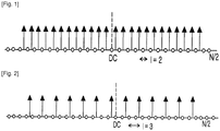
- pilot tones exist symmetrically with respect to a DC in the preamble
- received preamble data at a subcarrier of itself, an adjacent subcarrier, and two mirrored subcarriers of the above-mentioned subcarriers, that is, at four subcarrier indexes of k, k+1, -k, and -k-1
- information of the pilot tones are required in order to obtain estimated values of one phase difference and one amplitude difference.
- Equation (10) is expressed in terms of a phase difference and an amplitude difference as illustrated in Equation (12).
- Math Figure 13 [Math.
- Equation (1) a final estimated amplitude difference and phase difference are obtained as in Equation (1).
- Equation (2) a received signal at a null subcarrier index k is given by Equation (14).
- Equation (14) Equation (14).
- Equation (16) can be obtained using Equations (14) and (15).
- An I/Q unbalance can be estimated regardless of an influence of a channel and a gain influence of a pilot signal using Equation (16).
- An amplitude difference and a phase difference where all pilots are averaged to reduce an estimation error in one preamble are estimated by Equation (2).
- the averaging and selecting unit 318 calculates an average for only estimation values whose channel gain is greater than power of a noise and having higher correlation than those of adjacent pilot tones, and outputs the average to the I/Q unbalance compensator 302 through the integrator 320.
- the averaging and selecting unit 318 calculates an average for only estimation values of pilot tones where the channel gain is greater than power of a noise, and outputs the average to the I/Q unbalance compensator 302 through the integrator 320.
- Equation (18) is a real number meaning correlation.
- the number of subcarriers selected from calculation of Equation (1) can be controlled through the value ⁇ .
- pilots of a portion where a noise is large are excluded from a calculation process of Equation (2) using Equation (17).
- an estimation error is obtained by comparing a value of a pilot tone interfering with a null carrier with a null value, which is a pilot tone of an original signal itself. Therefore, interfered pilot tones should have a better gain than a noise in order to reduce an estimation error.
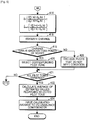
- FIGs. 4 and 5 are flowcharts illustrating a procedure for estimating I/Q parameters in an OFDM receiver according to an exemplary embodiment of the present invention.
- the OFDM receiver examines whether pilot tones exist symmetrically with respect to the DC in the preamble.
- a case where the pilot tones exist symmetrically with respect to the DC in the preamble means that pilot signals exist in a symmetric configuration around the DC as illustrated in FIG. 1 .
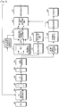
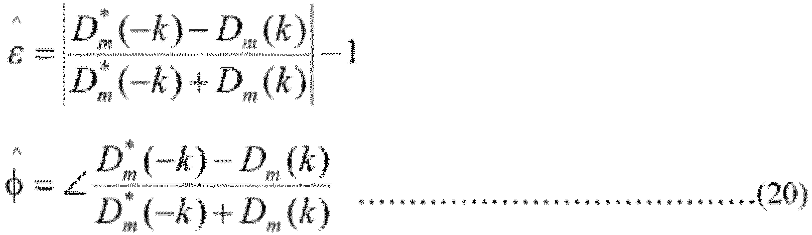
- a case where the pilot tones do not exist symmetrically with respect to the DC in the preamble means that pilots move one by one for each sector and interference is not generated between pilots as illustrated in FIG. 2 .
- the OFDM receiver calculates an amplitude difference ⁇ and a phase difference ⁇ as illustrated in Equation (1) in step 403.
- the OFDM receiver performs channel estimation on a received OFDM signal, and examines whether a channel gain is greater than the power of a noise in step 407.
- the reason whether the channel gain is greater than the power of the noise is examined is to exclude terms that do not meet the condition of Equation (17) and to input an estimation value having a small error to an I/Q unbalance compensator because when the size of a pilot signal has a smaller value than that of the noise, an estimation error becomes very large.
- the OFDM receiver excludes pilot tones that do not meet the condition in step 415, and goes back to step 410 to perform subsequent steps.
- the OFDM receiver examines whether a received pilot signal has higher correlation than adjacent pilot signals in step 408.
- the reason whether the received pilot signal has higher correlation than the adjacent pilot signals is examined is to reduce an estimation error even more, that is, to reduce an estimation error by excluding terms that do not meet the condition of Equation (18), i.e., pilot tones having low correlation.
- the OFDM receiver When the received pilot signal has lower correlation than the adjacent pilot signals, the OFDM receiver performs step 415 to perform subsequent steps. Meanwhile, when the received pilot signal has higher correlation than the adjacent pilot signals, the OFDEM receiver selects a corresponding pilot tone in step 409, and checks whether all pilot tones have been examined in step 410.
- the OFDM receiver goes back to step 407 to examine other pilot tones. Meanwhile, when all the pilot tones have been examined, the OFDM receiver calculates an average of estimation values regarding the selected pilot tone in step 411, and inputs the calculated average to the I/Q unbalance compensator in step 413. After that, the OFDM receiver ends an algorithm according to the exemplary embodiment of the present invention.
- the OFDM receiver performs step 416 to calculate an amplitude difference ⁇ and a phase difference ⁇ as expressed in Equation (2).
- the OFDM receiver performs channel estimation on a received OFDM signal, and examines whether a channel gain is greater than the power of a noise in step 419.
- the reason whether the channel gain is greater than the power of the noise is examined is to exclude terms that do not meet the condition and to input an estimation value having a small error to the I/Q unbalance compensator because when the size of a pilot signal has a smaller value than that of the noise, an estimation error becomes very large.
- the OFDM receiver excludes pilot tones that do not meet the condition in step 426, and goes to step 421 to perform subsequent steps.
- the OFDM receiver performs step 420 to select a corresponding pilot tone, and checks whether all pilot tones have been examined in step 421. When all the pilot tones have not been examined, the OFDM receiver goes back to step 419 to examine other pilot tones. Meanwhile, when all the pilot tones have been examined, the OFDM receiver calculates an average of estimation values regarding the selected pilot tone in step 422, and input the calculated average to the I/Q unbalance compensator in step 424. After that, the OFDM receiver ends an algorithm according to the exemplary embodiment of the present invention.
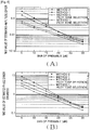
- SNR Signal-to-Noise Ratio
- an OFDM receiver estimates and compensates for a phase difference and an amplitude difference between an I channel and a Q channel through received one OFDM preamble value, so that the present invention has effects of being simply realized and correcting an I/Q unbalance in real-time.
Landscapes
- Engineering & Computer Science (AREA)
- Signal Processing (AREA)
- Computer Networks & Wireless Communication (AREA)
- Circuits Of Receivers In General (AREA)
- Noise Elimination (AREA)
- Cable Transmission Systems, Equalization Of Radio And Reduction Of Echo (AREA)
Claims (12)
- Vorrichtung zum Schätzen von I/Q-Ungleichgewichtsparametern in einem orthogonalen Frequenzmultiplex (OFDM) -Empfänger, wobei die Vorrichtung Folgendes umfasst:einen Ungleichgewichtschätzer zum Schätzen zwischen einem I-Kanal und einem Q-Kanal, einer Amplitudendifferenz und einer Phasendifferenz abhängig davon, ob Pilottöne symmetrisch in Bezug auf einen Gleichstrom (DC) in einer Präambel eines empfangenen Signals existieren; undeinen I/Q-Ungleichgewichtskompensator zum Kompensieren eines I/Q-Ungleichgewichts unter Verwendung der Amplitudendifferenz und der Phasendifferenz, die durch den Ungleichgewichtsparameterschätzer geschätzt werden.
- Vorrichtung nach Anspruch 1, wobei, wenn die Pilottöne symmetrisch in Bezug auf den Gleichstrom existieren, der Ungleichgewichtsparameterschätzer die Amplitudendifferenz und die Phasendifferenz unter Verwendung der folgenden Gleichung 19 schätzt:

- Vorrichtung nach Anspruch 2, wobei das Schätzen der Amplitudendifferenz und der Phasendifferenz das Vergleichen der Pilottöne mit einem Rauschen und das Auswählen eines Pilottons, der größer als das Rauschen ist, umfasst.
- Vorrichtung nach Anspruch 2, wobei das Schätzen der Amplitudendifferenz und der Phasendifferenz das Auswählen eines Pilottons mit einer höheren Korrelation als diejenigen benachbarter Pilottöne umfasst.
- Vorrichtung nach Anspruch 1, wobei, wenn die Pilottöne nicht symmetrisch in Bezug auf den Gleichstrom existieren, der Ungleichgewichtsparameterschätzer die Amplitudendifferenz und die Phasendifferenz unter Verwendung der folgenden Gleichung 20 schätzt:
- Vorrichtung nach Anspruch 5, wobei das Schätzen der Amplitudendifferenz und der Phasendifferenz das Vergleichen der Pilottöne mit einem Rauschen und das Auswählen eines Pilottons, der größer als das Rauschen ist, umfasst.
- Verfahren zum Schätzen von I/Q-Ungleichgewichtsparametern in einem orthogonalen Frequenzmultiplex (OFDM) -Empfänger, wobei das Verfahren Folgendes umfasst:Schätzen, zwischen einem I-Kanal und einem Q-Kanal, einer Amplitudendifferenz und einer Phasendifferenz abhängig davon, ob Pilottöne symmetrisch in Bezug auf einen Gleichstrom (DC) in einer Präambel eines empfangenen Signals existieren; undKompensieren eines I/Q-Ungleichgewichts unter Verwendung der geschätzten Amplitudendifferenz und Phasendifferenz.
- Verfahren nach Anspruch 7, wobei, wenn die Pilottöne symmetrisch in Bezug auf den Gleichstrom existieren, das Schätzen der Amplitudendifferenz und der Phasendifferenz das Schätzen der Amplitudendifferenz und der Phasendifferenz unter Verwendung der folgenden Gleichung 21 umfasst:

- Verfahren nach Anspruch 8, wobei das Schätzen der Amplitudendifferenz und der Phasendifferenz das Vergleichen der Pilottöne mit einem Rauschen und das Auswählen eines Pilottons, der größer als das Rauschen ist, umfasst.
- Verfahren nach Anspruch 8, wobei das Schätzen der Amplitudendifferenz und der Phasendifferenz das Auswählen eines Pilottons mit einer höheren Korrelation als diejenigen benachbarter Pilottöne umfasst.
- Verfahren nach Anspruch 7, wobei, wenn die Pilottöne nicht symmetrisch in Bezug auf den Gleichstrom existieren, das Schätzen der Amplitudendifferenz und der Phasendifferenz das Schätzen der Amplitudendifferenz und der Phasendifferenz unter Verwendung der folgenden Gleichung 22 umfasst:

- Verfahren nach Anspruch 11, wobei das Schätzen der Amplitudendifferenz und der Phasendifferenz das Vergleichen der Pilottöne mit einem Rauschen und das Auswählen eines Pilottons, der größer als das Rauschen ist, umfasst.
Applications Claiming Priority (2)
| Application Number | Priority Date | Filing Date | Title |
|---|---|---|---|
| KR1020080014749A KR101452995B1 (ko) | 2008-02-19 | 2008-02-19 | 직교 주파수 분할 다중 수신기에서 아이/큐 불균형파라미터를 추정하는 장치 및 방법 |
| PCT/KR2009/000789 WO2009104909A2 (en) | 2008-02-19 | 2009-02-19 | Apparatus and method for estimating i/q unbalance parameters in ofdm receiver |
Publications (3)
| Publication Number | Publication Date |
|---|---|
| EP2243266A2 EP2243266A2 (de) | 2010-10-27 |
| EP2243266A4 EP2243266A4 (de) | 2017-04-26 |
| EP2243266B1 true EP2243266B1 (de) | 2018-09-26 |
Family
ID=40986051
Family Applications (1)
| Application Number | Title | Priority Date | Filing Date |
|---|---|---|---|
| EP09712702.1A Not-in-force EP2243266B1 (de) | 2008-02-19 | 2009-02-19 | Vorrichtung und verfahren zur schätzung von i/q-ungleichgewichtsparametern in einem ofdm-empfänger |
Country Status (6)
| Country | Link |
|---|---|
| US (1) | US8467479B2 (de) |
| EP (1) | EP2243266B1 (de) |
| JP (1) | JP5576300B2 (de) |
| KR (1) | KR101452995B1 (de) |
| CN (1) | CN101946478B (de) |
| WO (1) | WO2009104909A2 (de) |
Families Citing this family (15)
| Publication number | Priority date | Publication date | Assignee | Title |
|---|---|---|---|---|
| KR101278025B1 (ko) | 2009-10-15 | 2013-06-21 | 한국전자통신연구원 | 직교 주파수 분할 다중화 방식의 i/q 불균형 보상을 위한 수신 장치 및 그 수신 장치에서 수행되는 i/q 불균형 보상 방법 |
| EP2337294B1 (de) * | 2009-12-21 | 2012-07-11 | TELEFONAKTIEBOLAGET LM ERICSSON (publ) | IQ-Ungleichgewichtseinschätzung für nicht symmetrische Pilotensymbole |
| US9178675B2 (en) * | 2012-02-27 | 2015-11-03 | Intel Corporation | Channel estimation and tracking |
| US9647863B2 (en) | 2012-02-27 | 2017-05-09 | Intel Corporation | Techniques to manage dwell times for pilot rotation |
| CN103036846B (zh) * | 2012-12-27 | 2015-09-09 | 上海创远仪器技术股份有限公司 | 应用于通信系统接收机的i/q不平衡补偿控制方法 |
| US20140198865A1 (en) * | 2013-01-16 | 2014-07-17 | Qualcomm Incorporated | Ofdm pilot and frame structures |
| WO2015012816A1 (en) * | 2013-07-23 | 2015-01-29 | Intel IP Corporation | Method for improving spectral efficiency in wi-fi ofdm systems |
| EP3082312B1 (de) | 2013-12-31 | 2017-09-13 | Huawei Technologies Co., Ltd. | Verfahren, vorrichtung und ausrüstung für frequenzkorrektur mit null zwischenfrequenz |
| US20170093458A1 (en) * | 2015-09-24 | 2017-03-30 | Qualcomm Incorporated | Online residual side band (rsb) calibration utilizing a frequency correction channel (fcch) |
| CN105791182B (zh) * | 2016-03-10 | 2018-10-23 | 东南大学 | 适用于mimo-ofdm系统的iq不平衡和信道联合估计方法 |
| CN108123905B (zh) * | 2017-12-20 | 2020-07-07 | 普联技术有限公司 | Iq不平衡的估计方法、估计装置、估计设备及存储介质 |
| KR102027674B1 (ko) | 2018-01-12 | 2019-10-02 | 한국과학기술원 | 강화 학습 기반 다중 안테나 송수신단의 i/q 불균형 파라미터 추정 방법 및 시스템 |
| WO2019193641A1 (ja) * | 2018-04-02 | 2019-10-10 | 三菱電機株式会社 | 無線通信装置 |
| CN112054983B (zh) * | 2020-08-21 | 2022-05-24 | 普联技术有限公司 | 一种ofdm接收机的信号幅度处理方法、装置及终端设备 |
| CN112887238B (zh) * | 2021-05-06 | 2021-07-20 | 上海擎昆信息科技有限公司 | 一种iq不平衡的校正方法及装置、接收机 |
Family Cites Families (20)
| Publication number | Priority date | Publication date | Assignee | Title |
|---|---|---|---|---|
| JP4039733B2 (ja) * | 1998-05-15 | 2008-01-30 | 三菱電機株式会社 | 搬送波周波数同期回路 |
| KR20030047591A (ko) * | 2001-12-11 | 2003-06-18 | (주)텔레시스테크놀로지 | 직교주파수분할다중방식의 이동통신 통신시스템의 신호보상장치 및 방법 |
| EP1525659A1 (de) * | 2002-08-02 | 2005-04-27 | Nokia Corporation | Quadraturdemodulator unter verwendung eines fft-prozessors |
| TW200501611A (en) * | 2003-03-12 | 2005-01-01 | Koninkl Philips Electronics Nv | Transceiver with mismatch compensation scheme |
| US7298793B2 (en) * | 2003-08-21 | 2007-11-20 | Mediatek Inc. | Method and apparatus for I/Q mismatch calibration of transmitter |
| US7570923B2 (en) * | 2004-05-18 | 2009-08-04 | Agere Systems Inc. | I/Q compensation of frequency dependent response mismatch in a pair of analog low-pass filters |
| US7466768B2 (en) * | 2004-06-14 | 2008-12-16 | Via Technologies, Inc. | IQ imbalance compensation |
| KR100606130B1 (ko) * | 2005-02-17 | 2006-07-28 | 삼성전자주식회사 | 제로 중간주파수 직교주파수 분할 다중 수신기에서의 최적동위상/직교위상 불균형 보상 장치 및 방법 |
| US7474711B2 (en) * | 2005-05-06 | 2009-01-06 | Motorola, Inc | Method and system for I/Q imbalance and DC offset correction |
| JP2007142674A (ja) * | 2005-11-16 | 2007-06-07 | Matsushita Electric Ind Co Ltd | マルチキャリア送信装置、マルチキャリア受信装置及び通信方法 |
| JP4406398B2 (ja) * | 2005-12-26 | 2010-01-27 | 株式会社東芝 | Ofdm信号の送信方法と送信装置及びofdm信号の受信装置 |
| JP4550746B2 (ja) * | 2006-02-01 | 2010-09-22 | 株式会社東芝 | Ofdmを用いた無線通信方法、ofdm送信装置及びofdm受信装置 |
| KR100896203B1 (ko) * | 2006-02-24 | 2009-05-12 | 삼성전자주식회사 | 광대역무선접속시스템에서 데이터 복조를 위한 채널추정장치 및 방법 |
| JP4213734B2 (ja) * | 2006-07-05 | 2009-01-21 | 株式会社東芝 | Ofdmを用いた無線通信方法及びofdm受信装置 |
| US8503545B2 (en) * | 2006-08-31 | 2013-08-06 | Advanced Micro Devices, Inc. | I/Q imbalance compensation |
| JP4261578B2 (ja) * | 2006-12-27 | 2009-04-30 | 株式会社東芝 | 無線通信装置及び受信方法 |
| JP2008283288A (ja) * | 2007-05-08 | 2008-11-20 | Toshiba Corp | 無線送信装置及び方法 |
| JP4421635B2 (ja) * | 2007-06-18 | 2010-02-24 | 株式会社東芝 | 無線通信方法及び無線通信装置 |
| US20090122918A1 (en) * | 2007-11-06 | 2009-05-14 | Augusta Technology, Inc. | Methods for Compensating for I/Q Imbalance in OFDM Systems |
| JP2009147498A (ja) * | 2007-12-12 | 2009-07-02 | Sharp Corp | 送信機、送信機制御方法、送信機制御プログラム、受信機、受信機制御方法、受信機制御プログラム及び無線通信システム |
-
2008
- 2008-02-19 KR KR1020080014749A patent/KR101452995B1/ko not_active Expired - Fee Related
-
2009
- 2009-02-19 WO PCT/KR2009/000789 patent/WO2009104909A2/en not_active Ceased
- 2009-02-19 EP EP09712702.1A patent/EP2243266B1/de not_active Not-in-force
- 2009-02-19 US US12/918,246 patent/US8467479B2/en not_active Expired - Fee Related
- 2009-02-19 JP JP2010547563A patent/JP5576300B2/ja not_active Expired - Fee Related
- 2009-02-19 CN CN200980105676.4A patent/CN101946478B/zh not_active Expired - Fee Related
Also Published As
| Publication number | Publication date |
|---|---|
| JP2011512770A (ja) | 2011-04-21 |
| CN101946478B (zh) | 2014-01-01 |
| KR101452995B1 (ko) | 2014-10-23 |
| EP2243266A2 (de) | 2010-10-27 |
| KR20090089531A (ko) | 2009-08-24 |
| EP2243266A4 (de) | 2017-04-26 |
| US8467479B2 (en) | 2013-06-18 |
| WO2009104909A2 (en) | 2009-08-27 |
| WO2009104909A3 (en) | 2009-10-22 |
| JP5576300B2 (ja) | 2014-08-20 |
| CN101946478A (zh) | 2011-01-12 |
| US20100329394A1 (en) | 2010-12-30 |
Similar Documents
| Publication | Publication Date | Title |
|---|---|---|
| EP2243266B1 (de) | Vorrichtung und verfahren zur schätzung von i/q-ungleichgewichtsparametern in einem ofdm-empfänger | |
| EP2109273B1 (de) | Verfahren und Anordnung zur Einschätzung des IQ-Ungleichgewichts | |
| CN102196486B (zh) | 正交频分复用系统参考信号接收功率测量方法和装置 | |
| US20120099631A1 (en) | Pilot-based time offset estimation apparatus and method | |
| EP2453587B1 (de) | Verfahren, vorrichtung und system zur übertragung von kanalstatusinformationen | |
| WO2009046001A1 (en) | Techniques for estimating received signal strength and carrier to interference and noise ratio in ofdm systems | |
| US8743987B2 (en) | Symbol detection for alleviating inter-symbol interference | |
| EP2360883B1 (de) | Detektion eines übertragenen OFDM-Signals in einem Empfänger mit mindestens zwei Empfangszweigen | |
| CN108696305B (zh) | 适用于lte-a mimo信号分析系统的高精度频偏测量方法 | |
| JP3910956B2 (ja) | Ofdm無線通信システムのための伝搬路推定器及びこれを用いた受信装置 | |
| US20120320729A1 (en) | Apparatus and method for receiving signal in wireless communication system | |
| JP5147089B2 (ja) | Ofdm通信システムにおけるアナログ損失のハイブリッドドメイン補償パラメータの求め方と補償方法 | |
| CN116527458B (zh) | 5g小基站的dmrs信号的snr估计方法和装置 | |
| WO2007078095A1 (en) | Frequency offset estimation apparatus and method in wireless telecommunication system | |
| EP2337294A1 (de) | IQ-Ungleichgewichtseinschätzung für nicht symmetrische Pilotensymbole | |
| JP2008028515A (ja) | 受信装置、受信方法、及びプログラム | |
| US8416674B2 (en) | Method and apparatus for receiving minimum mean-squared-error in single-carrier frequency division multiple access system | |
| JP5625719B2 (ja) | 無線受信装置および無線受信方法 | |
| KR101932991B1 (ko) | 무선 통신 시스템에서 신호 수신 장치 및 방법 | |
| EP3035567B1 (de) | Verfahren und vorrichtung zur schätzung der rauschleistung | |
| Sagong et al. | A novel blind interference cancellation receiver for LTE uplink SC-FDMA systems | |
| HK1191768A (en) | Secondary synchronization signal detection with interference cancelation for lte |
Legal Events
| Date | Code | Title | Description |
|---|---|---|---|
| PUAI | Public reference made under article 153(3) epc to a published international application that has entered the european phase |
Free format text: ORIGINAL CODE: 0009012 |
|
| 17P | Request for examination filed |
Effective date: 20100805 |
|
| AK | Designated contracting states |
Kind code of ref document: A2 Designated state(s): AT BE BG CH CY CZ DE DK EE ES FI FR GB GR HR HU IE IS IT LI LT LU LV MC MK MT NL NO PL PT RO SE SI SK TR |
|
| AX | Request for extension of the european patent |
Extension state: AL BA RS |
|
| DAX | Request for extension of the european patent (deleted) | ||
| RAP1 | Party data changed (applicant data changed or rights of an application transferred) |
Owner name: SAMSUNG ELECTRONICS CO., LTD. |
|
| A4 | Supplementary search report drawn up and despatched |
Effective date: 20170328 |
|
| RIC1 | Information provided on ipc code assigned before grant |
Ipc: H04L 27/26 20060101AFI20170322BHEP |
|
| GRAP | Despatch of communication of intention to grant a patent |
Free format text: ORIGINAL CODE: EPIDOSNIGR1 |
|
| STAA | Information on the status of an ep patent application or granted ep patent |
Free format text: STATUS: GRANT OF PATENT IS INTENDED |
|
| RIN1 | Information on inventor provided before grant (corrected) |
Inventor name: BAE, JUNG-HWA Inventor name: BAE, SANG-MIN |
|
| INTG | Intention to grant announced |
Effective date: 20180424 |
|
| GRAS | Grant fee paid |
Free format text: ORIGINAL CODE: EPIDOSNIGR3 |
|
| GRAA | (expected) grant |
Free format text: ORIGINAL CODE: 0009210 |
|
| STAA | Information on the status of an ep patent application or granted ep patent |
Free format text: STATUS: THE PATENT HAS BEEN GRANTED |
|
| AK | Designated contracting states |
Kind code of ref document: B1 Designated state(s): AT BE BG CH CY CZ DE DK EE ES FI FR GB GR HR HU IE IS IT LI LT LU LV MC MK MT NL NO PL PT RO SE SI SK TR |
|
| REG | Reference to a national code |
Ref country code: GB Ref legal event code: FG4D |
|
| REG | Reference to a national code |
Ref country code: CH Ref legal event code: EP |
|
| REG | Reference to a national code |
Ref country code: AT Ref legal event code: REF Ref document number: 1047358 Country of ref document: AT Kind code of ref document: T Effective date: 20181015 |
|
| REG | Reference to a national code |
Ref country code: IE Ref legal event code: FG4D |
|
| REG | Reference to a national code |
Ref country code: DE Ref legal event code: R096 Ref document number: 602009054731 Country of ref document: DE |
|
| REG | Reference to a national code |
Ref country code: NL Ref legal event code: MP Effective date: 20180926 |
|
| PG25 | Lapsed in a contracting state [announced via postgrant information from national office to epo] |
Ref country code: LT Free format text: LAPSE BECAUSE OF FAILURE TO SUBMIT A TRANSLATION OF THE DESCRIPTION OR TO PAY THE FEE WITHIN THE PRESCRIBED TIME-LIMIT Effective date: 20180926 Ref country code: FI Free format text: LAPSE BECAUSE OF FAILURE TO SUBMIT A TRANSLATION OF THE DESCRIPTION OR TO PAY THE FEE WITHIN THE PRESCRIBED TIME-LIMIT Effective date: 20180926 Ref country code: GR Free format text: LAPSE BECAUSE OF FAILURE TO SUBMIT A TRANSLATION OF THE DESCRIPTION OR TO PAY THE FEE WITHIN THE PRESCRIBED TIME-LIMIT Effective date: 20181227 Ref country code: NO Free format text: LAPSE BECAUSE OF FAILURE TO SUBMIT A TRANSLATION OF THE DESCRIPTION OR TO PAY THE FEE WITHIN THE PRESCRIBED TIME-LIMIT Effective date: 20181226 Ref country code: BG Free format text: LAPSE BECAUSE OF FAILURE TO SUBMIT A TRANSLATION OF THE DESCRIPTION OR TO PAY THE FEE WITHIN THE PRESCRIBED TIME-LIMIT Effective date: 20181226 Ref country code: SE Free format text: LAPSE BECAUSE OF FAILURE TO SUBMIT A TRANSLATION OF THE DESCRIPTION OR TO PAY THE FEE WITHIN THE PRESCRIBED TIME-LIMIT Effective date: 20180926 |
|
| REG | Reference to a national code |
Ref country code: LT Ref legal event code: MG4D |
|
| PG25 | Lapsed in a contracting state [announced via postgrant information from national office to epo] |
Ref country code: LV Free format text: LAPSE BECAUSE OF FAILURE TO SUBMIT A TRANSLATION OF THE DESCRIPTION OR TO PAY THE FEE WITHIN THE PRESCRIBED TIME-LIMIT Effective date: 20180926 Ref country code: HR Free format text: LAPSE BECAUSE OF FAILURE TO SUBMIT A TRANSLATION OF THE DESCRIPTION OR TO PAY THE FEE WITHIN THE PRESCRIBED TIME-LIMIT Effective date: 20180926 |
|
| REG | Reference to a national code |
Ref country code: AT Ref legal event code: MK05 Ref document number: 1047358 Country of ref document: AT Kind code of ref document: T Effective date: 20180926 |
|
| PG25 | Lapsed in a contracting state [announced via postgrant information from national office to epo] |
Ref country code: ES Free format text: LAPSE BECAUSE OF FAILURE TO SUBMIT A TRANSLATION OF THE DESCRIPTION OR TO PAY THE FEE WITHIN THE PRESCRIBED TIME-LIMIT Effective date: 20180926 Ref country code: IS Free format text: LAPSE BECAUSE OF FAILURE TO SUBMIT A TRANSLATION OF THE DESCRIPTION OR TO PAY THE FEE WITHIN THE PRESCRIBED TIME-LIMIT Effective date: 20190126 Ref country code: EE Free format text: LAPSE BECAUSE OF FAILURE TO SUBMIT A TRANSLATION OF THE DESCRIPTION OR TO PAY THE FEE WITHIN THE PRESCRIBED TIME-LIMIT Effective date: 20180926 Ref country code: PL Free format text: LAPSE BECAUSE OF FAILURE TO SUBMIT A TRANSLATION OF THE DESCRIPTION OR TO PAY THE FEE WITHIN THE PRESCRIBED TIME-LIMIT Effective date: 20180926 Ref country code: IT Free format text: LAPSE BECAUSE OF FAILURE TO SUBMIT A TRANSLATION OF THE DESCRIPTION OR TO PAY THE FEE WITHIN THE PRESCRIBED TIME-LIMIT Effective date: 20180926 Ref country code: RO Free format text: LAPSE BECAUSE OF FAILURE TO SUBMIT A TRANSLATION OF THE DESCRIPTION OR TO PAY THE FEE WITHIN THE PRESCRIBED TIME-LIMIT Effective date: 20180926 Ref country code: AT Free format text: LAPSE BECAUSE OF FAILURE TO SUBMIT A TRANSLATION OF THE DESCRIPTION OR TO PAY THE FEE WITHIN THE PRESCRIBED TIME-LIMIT Effective date: 20180926 Ref country code: CZ Free format text: LAPSE BECAUSE OF FAILURE TO SUBMIT A TRANSLATION OF THE DESCRIPTION OR TO PAY THE FEE WITHIN THE PRESCRIBED TIME-LIMIT Effective date: 20180926 Ref country code: NL Free format text: LAPSE BECAUSE OF FAILURE TO SUBMIT A TRANSLATION OF THE DESCRIPTION OR TO PAY THE FEE WITHIN THE PRESCRIBED TIME-LIMIT Effective date: 20180926 |
|
| PG25 | Lapsed in a contracting state [announced via postgrant information from national office to epo] |
Ref country code: SK Free format text: LAPSE BECAUSE OF FAILURE TO SUBMIT A TRANSLATION OF THE DESCRIPTION OR TO PAY THE FEE WITHIN THE PRESCRIBED TIME-LIMIT Effective date: 20180926 Ref country code: PT Free format text: LAPSE BECAUSE OF FAILURE TO SUBMIT A TRANSLATION OF THE DESCRIPTION OR TO PAY THE FEE WITHIN THE PRESCRIBED TIME-LIMIT Effective date: 20190126 |
|
| REG | Reference to a national code |
Ref country code: DE Ref legal event code: R097 Ref document number: 602009054731 Country of ref document: DE |
|
| PG25 | Lapsed in a contracting state [announced via postgrant information from national office to epo] |
Ref country code: DK Free format text: LAPSE BECAUSE OF FAILURE TO SUBMIT A TRANSLATION OF THE DESCRIPTION OR TO PAY THE FEE WITHIN THE PRESCRIBED TIME-LIMIT Effective date: 20180926 |
|
| PLBE | No opposition filed within time limit |
Free format text: ORIGINAL CODE: 0009261 |
|
| STAA | Information on the status of an ep patent application or granted ep patent |
Free format text: STATUS: NO OPPOSITION FILED WITHIN TIME LIMIT |
|
| 26N | No opposition filed |
Effective date: 20190627 |
|
| REG | Reference to a national code |
Ref country code: CH Ref legal event code: PL |
|
| PG25 | Lapsed in a contracting state [announced via postgrant information from national office to epo] |
Ref country code: SI Free format text: LAPSE BECAUSE OF FAILURE TO SUBMIT A TRANSLATION OF THE DESCRIPTION OR TO PAY THE FEE WITHIN THE PRESCRIBED TIME-LIMIT Effective date: 20180926 Ref country code: MC Free format text: LAPSE BECAUSE OF FAILURE TO SUBMIT A TRANSLATION OF THE DESCRIPTION OR TO PAY THE FEE WITHIN THE PRESCRIBED TIME-LIMIT Effective date: 20180926 Ref country code: LU Free format text: LAPSE BECAUSE OF NON-PAYMENT OF DUE FEES Effective date: 20190219 |
|
| REG | Reference to a national code |
Ref country code: BE Ref legal event code: MM Effective date: 20190228 |
|
| REG | Reference to a national code |
Ref country code: IE Ref legal event code: MM4A |
|
| PG25 | Lapsed in a contracting state [announced via postgrant information from national office to epo] |
Ref country code: LI Free format text: LAPSE BECAUSE OF NON-PAYMENT OF DUE FEES Effective date: 20190228 Ref country code: CH Free format text: LAPSE BECAUSE OF NON-PAYMENT OF DUE FEES Effective date: 20190228 |
|
| PG25 | Lapsed in a contracting state [announced via postgrant information from national office to epo] |
Ref country code: IE Free format text: LAPSE BECAUSE OF NON-PAYMENT OF DUE FEES Effective date: 20190219 |
|
| PG25 | Lapsed in a contracting state [announced via postgrant information from national office to epo] |
Ref country code: BE Free format text: LAPSE BECAUSE OF NON-PAYMENT OF DUE FEES Effective date: 20190228 Ref country code: FR Free format text: LAPSE BECAUSE OF NON-PAYMENT OF DUE FEES Effective date: 20190228 |
|
| PG25 | Lapsed in a contracting state [announced via postgrant information from national office to epo] |
Ref country code: TR Free format text: LAPSE BECAUSE OF FAILURE TO SUBMIT A TRANSLATION OF THE DESCRIPTION OR TO PAY THE FEE WITHIN THE PRESCRIBED TIME-LIMIT Effective date: 20180926 |
|
| PGFP | Annual fee paid to national office [announced via postgrant information from national office to epo] |
Ref country code: DE Payment date: 20200121 Year of fee payment: 12 Ref country code: GB Payment date: 20200123 Year of fee payment: 12 |
|
| PG25 | Lapsed in a contracting state [announced via postgrant information from national office to epo] |
Ref country code: MT Free format text: LAPSE BECAUSE OF NON-PAYMENT OF DUE FEES Effective date: 20190219 |
|
| PG25 | Lapsed in a contracting state [announced via postgrant information from national office to epo] |
Ref country code: CY Free format text: LAPSE BECAUSE OF FAILURE TO SUBMIT A TRANSLATION OF THE DESCRIPTION OR TO PAY THE FEE WITHIN THE PRESCRIBED TIME-LIMIT Effective date: 20180926 |
|
| PG25 | Lapsed in a contracting state [announced via postgrant information from national office to epo] |
Ref country code: HU Free format text: LAPSE BECAUSE OF FAILURE TO SUBMIT A TRANSLATION OF THE DESCRIPTION OR TO PAY THE FEE WITHIN THE PRESCRIBED TIME-LIMIT; INVALID AB INITIO Effective date: 20090219 |
|
| REG | Reference to a national code |
Ref country code: DE Ref legal event code: R119 Ref document number: 602009054731 Country of ref document: DE |
|
| GBPC | Gb: european patent ceased through non-payment of renewal fee |
Effective date: 20210219 |
|
| PG25 | Lapsed in a contracting state [announced via postgrant information from national office to epo] |
Ref country code: DE Free format text: LAPSE BECAUSE OF NON-PAYMENT OF DUE FEES Effective date: 20210901 Ref country code: GB Free format text: LAPSE BECAUSE OF NON-PAYMENT OF DUE FEES Effective date: 20210219 |
|
| PG25 | Lapsed in a contracting state [announced via postgrant information from national office to epo] |
Ref country code: MK Free format text: LAPSE BECAUSE OF FAILURE TO SUBMIT A TRANSLATION OF THE DESCRIPTION OR TO PAY THE FEE WITHIN THE PRESCRIBED TIME-LIMIT Effective date: 20180926 |