EP2242001A2 - Drucksystem und Druckverfahren - Google Patents
Drucksystem und Druckverfahren Download PDFInfo
- Publication number
- EP2242001A2 EP2242001A2 EP10160066A EP10160066A EP2242001A2 EP 2242001 A2 EP2242001 A2 EP 2242001A2 EP 10160066 A EP10160066 A EP 10160066A EP 10160066 A EP10160066 A EP 10160066A EP 2242001 A2 EP2242001 A2 EP 2242001A2
- Authority
- EP
- European Patent Office
- Prior art keywords
- data
- print control
- control apparatus
- printing
- information
- Prior art date
- Legal status (The legal status is an assumption and is not a legal conclusion. Google has not performed a legal analysis and makes no representation as to the accuracy of the status listed.)
- Withdrawn
Links
Images


Classifications
-
- G—PHYSICS
- G06—COMPUTING OR CALCULATING; COUNTING
- G06K—GRAPHICAL DATA READING; PRESENTATION OF DATA; RECORD CARRIERS; HANDLING RECORD CARRIERS
- G06K15/00—Arrangements for producing a permanent visual presentation of the output data, e.g. computer output printers
-
- G—PHYSICS
- G06—COMPUTING OR CALCULATING; COUNTING
- G06F—ELECTRIC DIGITAL DATA PROCESSING
- G06F3/00—Input arrangements for transferring data to be processed into a form capable of being handled by the computer; Output arrangements for transferring data from processing unit to output unit, e.g. interface arrangements
- G06F3/12—Digital output to print unit, e.g. line printer, chain printer
- G06F3/1201—Dedicated interfaces to print systems
- G06F3/1202—Dedicated interfaces to print systems specifically adapted to achieve a particular effect
- G06F3/1203—Improving or facilitating administration, e.g. print management
- G06F3/1204—Improving or facilitating administration, e.g. print management resulting in reduced user or operator actions, e.g. presetting, automatic actions, using hardware token storing data
-
- G—PHYSICS
- G06—COMPUTING OR CALCULATING; COUNTING
- G06F—ELECTRIC DIGITAL DATA PROCESSING
- G06F3/00—Input arrangements for transferring data to be processed into a form capable of being handled by the computer; Output arrangements for transferring data from processing unit to output unit, e.g. interface arrangements
- G06F3/12—Digital output to print unit, e.g. line printer, chain printer
- G06F3/1201—Dedicated interfaces to print systems
- G06F3/1202—Dedicated interfaces to print systems specifically adapted to achieve a particular effect
- G06F3/1203—Improving or facilitating administration, e.g. print management
- G06F3/1207—Improving or facilitating administration, e.g. print management resulting in the user being informed about print result after a job submission
-
- G—PHYSICS
- G06—COMPUTING OR CALCULATING; COUNTING
- G06F—ELECTRIC DIGITAL DATA PROCESSING
- G06F3/00—Input arrangements for transferring data to be processed into a form capable of being handled by the computer; Output arrangements for transferring data from processing unit to output unit, e.g. interface arrangements
- G06F3/12—Digital output to print unit, e.g. line printer, chain printer
- G06F3/1201—Dedicated interfaces to print systems
- G06F3/1223—Dedicated interfaces to print systems specifically adapted to use a particular technique
- G06F3/1237—Print job management
- G06F3/1259—Print job monitoring, e.g. job status
-
- G—PHYSICS
- G06—COMPUTING OR CALCULATING; COUNTING
- G06F—ELECTRIC DIGITAL DATA PROCESSING
- G06F3/00—Input arrangements for transferring data to be processed into a form capable of being handled by the computer; Output arrangements for transferring data from processing unit to output unit, e.g. interface arrangements
- G06F3/12—Digital output to print unit, e.g. line printer, chain printer
- G06F3/1201—Dedicated interfaces to print systems
- G06F3/1278—Dedicated interfaces to print systems specifically adapted to adopt a particular infrastructure
- G06F3/1285—Remote printer device, e.g. being remote from client or server
- G06F3/1288—Remote printer device, e.g. being remote from client or server in client-server-printer device configuration
Definitions
- the present invention relates to a printing system and a printing method for printing a document.
- an external print control apparatus (print controller) is connected to a printing apparatus via a local network such as Ethernet® and can be identified by a single piece of apparatus information (e.g., IP address). All data is sent to the printing apparatus via the print control apparatus.
- apparatus information e.g., IP address
- processible print data is only that described in a printer description language compatible with the print control apparatus. Even if the printing apparatus can copy with a different printer description language, its function cannot be exploited (Japanese Patent Laid-Open No. 2002-312140 ).
- the print control apparatus and printing apparatus need to hold different pieces of apparatus information. With two different pieces of apparatus information held in the print control apparatus and printing apparatus, these apparatuses can receive and process different print data. Further, data using a function such as FAX or BOX processible by the printing apparatus can be sent directly to the printing apparatus.
- a print server When a print server, a plurality of printing apparatuses and a plurality of information processing apparatuses are connected to a network and a designated printing apparatus is not available, data is transferred to another printing apparatus on the network (Japanese Patent Laid-Open No. 7-281847 ). According to this method, the print server monitors and manages the use status of printing apparatuses in order to increase the use efficiency of those that are present on the network.
- An aspect of the present invention is to eliminate the above-mentioned problems with the conventional technology.
- the present invention provides a printing system and a printing method for improving the user friendliness of the printing system by transmitting data to an apparatus the user of an information processing apparatus originally intends even if the user sets the wrong apparatus information.
- the present invention in its first aspect provides a printing system as specified in claims 1 to 4.
- the present invention in its second aspect provides a printing method executed in a printing system as specified in claims 5 to 9.
- the present invention can improve the user friendliness of the printing system by transmitting print data to an apparatus the user of an information processing apparatus originally intends even if he sets wrong apparatus information.
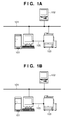
- Fig. 1A is a view showing an example of the overall configuration of a printing system
- Fig. 1B is a view showing another example of the overall configuration of the printing system
- Fig. 2 is a block diagram showing an arrangement of a print control unit (controller);
- Fig. 3 is a block diagram showing an arrangement of a printing apparatus
- Fig. 4 is a flowchart showing processing procedures when a wrong IP address is set
- Fig. 5 is a flowchart showing the procedures of transfer processing from the print control apparatus to the printing apparatus
- Fig. 6 is a flowchart showing processing procedures when the print control apparatus notifies an information processing apparatus of an error
- Fig. 7 is a view showing a window for setting transfer processing between the print control apparatus and the printing apparatus;
- Fig. 8 is a view showing a window for setting details of transfer processing and an error notification
- Fig. 9A is a view showing an example of a message in the error notification
- Fig. 9B is a view showing another example of the message in the error notification.
- Fig. 10 is a view exemplifying an output error notification page
- Fig. 11 is a flowchart showing processing procedures to confirm transfer conditions and transfer data
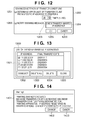
- Fig. 12 is a view showing a window for setting transfer conditions
- Fig. 13 is a view showing a list of the IP addresses of information processing apparatuses, transfer from which is inhibited.
- Fig. 14 is a view showing a window displayed when the transfer count has reached the upper limit.
- Fig. 1A is a view showing the overall configuration of a printing system in the first embodiment.
- a print control apparatus 101 which controls a printing apparatus 103 is connected to a LAN 104 serving as a network.
- the LAN 104 is laid between an information processing apparatus 102 which designates print processing for a document, the print control apparatus 101, and the printing apparatus 103 which prints.
- a LAN 105 is connected between the printing apparatus 103 and the print control apparatus 101 via a network interface.
- the printing apparatus 103 is further connected to the LAN 104 via a network interface.
- the print control apparatus 101 and printing apparatus 103 have different pieces of apparatus information.
- the apparatus information is information unique to an apparatus and is, e.g., an IP address.
- Data transmitted from the information processing apparatus 102 to the print control apparatus 101 propagates through the LAN 104 and is received by the print control apparatus 101. After RIP processing, the data propagates through the LAN 105 to the printing apparatus 103, and then is output from it.
- data transmitted from the information processing apparatus 102 to the printing apparatus 103 propagates through the LAN 104, and is received and processed by the printing apparatus 103.
- the LAN 104 allows the connection of other information processing apparatuses and printing apparatuses.
- Fig. 1B shows the configuration of a conventional printing system including a print control apparatus and printing apparatus.
- the printing apparatus 103 is not connected to the LAN 104 and only the print control apparatus 101 is connected to the LAN 104.
- the information processing apparatus 102 sets the IP address of the print control apparatus 101 and inputs data to the print control apparatus 101. Data processible by the printing apparatus 103 propagates through the LAN 105 and is received by the printing apparatus 103.
- Fig. 2 is a block diagram exemplifying the arrangement of a print control unit (controller) in the embodiment.
- a NIC Network Interface Card
- a RIP processing unit 202 converts a received printer description language such as PDL into a raster image.
- a CPU 203 controls the whole print control apparatus.
- An encoder 206 converts raster image data into print data or a data format in a form supported by the printing apparatus 103.
- a NIC 207 is the second network interface for connecting the print control unit to the LAN 105.
- An HDD (Hard Disk Drive) 208 stores system software for a variety of processes, input image data, and the like.
- a RAM 209 is a system work memory used when the CPU 203 runs, and temporarily stores input image data.
- a ROM 210 is a boot ROM which stores a system boot program.
- An operation unit 204 includes buttons, keys, and a touch panel and allows a user to manipulate the print control apparatus.
- a display unit 205 presents information by an image and text to the user.
- Fig. 3 is a block diagram showing an arrangement of the printing apparatus.
- the printing apparatus 103 may be, for example, an MFP (Multi Function Peripheral) having multiple functions such as a scanner function and print function.
- An input image processing unit 301 reads a paper document or the like with an image reading device such as a scanner, and processes the read image data.
- An output image processing unit 303 performs image processing for printing, and sends the processed data to a printer unit 302.
- the printer unit 302 feeds a sheet serving as a print medium, and sequentially prints image data processed by the output image processing unit on the sheet.
- the printed sheet is sent to a post-processing unit 304, and undergoes sheet sorting processing and sheet finishing processing.
- the information processing apparatus 102 shown in Figs. 1A and 1B is, for example, a general-purpose PC including memories such as a ROM, RAM, and HDD in addition to a CPU.
- a case will be explained, in which the print control apparatus 101 and printing apparatus 103 cope with different printer description languages.
- a user sets a first IP address of the print control apparatus 101 and a second IP address of the printing apparatus 103 in a printer driver installed in the information processing apparatus 102.
- the first and the second IP address as set by the user are wrong (e.g. the first IP address is actually for the printing apparatus 103 and the second IP address is actually for the print control apparatus 101) then print data is not transmitted to a destination the user wants.
- the print control apparatus and printing apparatus did not hold IP addresses different from each other, so data were rarely transmitted to a wrong IP address. However, such a case would occur because the print control apparatus and printing apparatus hold different IP addresses now.
- Fig. 4 is a flowchart showing processing procedures by the information processing apparatus when a printer driver is installed in the information processing apparatus 102, a wrong IP address is set in the printer driver, and print data is transmitted.
- the printer driver is installed with the IP address of the print control apparatus 101 or printing apparatus 103 in accordance with an instruction from the user.
- the print control apparatus 101 and printing apparatus 103 have different IP addresses. Even if the printer driver of the print control apparatus 101 is installed, the IP address of the printing apparatus 103 may be set. Reversely, even if the printer driver of the printing apparatus 103 is installed, the IP address of the print control apparatus 101 may be set.
- the information processing apparatus 102 cannot determine that a wrong IP address has been set. In S402, therefore, the information processing apparatus 102 directly transmits print data to the destination of the IP address set in S401. In S403, the information processing apparatus 102 receives an error message from the destination of the IP address to which the data has been transmitted. In S404, the information processing apparatus 102 changes the IP address registered in the printer driver in accordance with an IP address change instruction from the user.
- Fig. 5 is a flowchart showing processing procedures when the print control apparatus 101 receives data which should be originally transmitted to the printing apparatus 103, and transfers the print data to the printing apparatus 103.
- the print control apparatus 101 acquires apparatus information of the printing apparatus 103.
- the apparatus information includes at least information indicating the IP address of the printing apparatus and the performance of the printing apparatus 103 such as a compatible printer description language.
- the print control apparatus 101 acquires these kinds of information immediately after it is activated and becomes communicable with the printing apparatus 103.
- the print control apparatus 101 and printing apparatus 103 exchange their apparatus information upon activation, and each apparatus acquires partner's apparatus information.
- the print control apparatus 101 receives print data from the information processing apparatus 102.
- the print control apparatus 101 determines whether the print data received in S502 is data processible by the print control apparatus 101. If the print control apparatus 101 determines that the received print data is data processible by the print control apparatus 101, it advances to S505; if NO, to S504. In S505, the print control apparatus 101 performs normal data processing for the print data.
- the print control apparatus 101 determines whether to transfer the received print data to the printing apparatus 103. This determination complies with a transfer processing mode set in Fig. 7 (to be described later). If the print control apparatus 101 determines not to transfer the received print data, it advances to S506. If the print control apparatus 101 determines to transfer the received print data, it advances to S507.
- the print control apparatus 101 determines whether to notify the user that the received print data has not been processed. This determination complies with an error notification setting selected in Fig. 8 (to be described later). If the print control apparatus 101 determines not to notify the user of the error, it advances to S509. If the print control apparatus 101 determines to notify the user of the error, it advances to S508. In S508, the print control apparatus 101 performs error notification processing. In S509, the print control apparatus 101 deletes the received print data from it.
- the print control apparatus 101 transfers the print data to the printing apparatus 103.
- the print control apparatus 101 determines whether to notify the information processing apparatus 102 that the print control apparatus 101 has transferred the print data to the printing apparatus 103. This determination complies with error notification setting contents shown in Fig. 8 . If the print control apparatus 101 determines to notify the information processing apparatus 102 that the print data has been transferred, it advances to S511; if NO, ends the processing. In S511, the print control apparatus 101 executes error notification processing, similar to S508. This sequence is done even when the printing apparatus 103 transfers received print data to the print control apparatus 101.
- Fig. 6 is a flowchart showing processing procedures when the print control apparatus 101 transfers received print data to the printing apparatus 103 and notifies the information processing apparatus 102 of an error.
- the print control apparatus 101 acquires error notification setting contents shown in Fig. 8 .
- the print control apparatus 101 acquires transfer result information indicating that data has been transferred to a correct IP address, or has not been transferred to it and deleted.
- the print control apparatus 101 acquires a correct IP address from apparatus information of the printing apparatus 103 that has been acquired in S501 of Fig. 5 .
- the print control apparatus 101 determines whether to print an error notification. If the user has selected printing of an error notification page at a setting 802 shown in Fig. 8 , the print control apparatus 101 advances to S605; if NO, to S607. In S605, the print control apparatus 101 acquires an IP address change method. In S606, the print control apparatus 101 transmits information to the printing apparatus 103 and requests it to print, in order to print the acquired correct IP address and IP address change method on the error notification page. In S607, the print control apparatus 101 transmits an error message to the information processing apparatus 102 to display it. In the embodiment, notifying the information processing apparatus 102 of an error message by performing the processing shown in Fig. 6 by the print control apparatus 101 will be defined as the first notification. Notifying the information processing apparatus 102 of an error message by performing the processing shown in Fig. 6 by the printing apparatus 103 will be defined as the second notification.
- the printing apparatus 103 transfers received print data to the print control apparatus 101 and prints an error notification, it outputs the acquired correct IP address and IP address change method in S606 without transmitting them to the print control apparatus 101.
- Fig. 7 shows a setup window which can be set by the print control apparatus 101 in order to set transfer processing between the print control apparatus 101 and the printing apparatus 103.
- a setting 701 in a window 700 is used to determine whether to perform transfer processing from the print control apparatus 101 to the printing apparatus 103.
- a setting 702 is used to set whether data to be transferred contains status data and print job data when the user sets execution of transfer at the setting 701. Data set at the setting 702 is transferred to the printing apparatus 103.
- An OK button 703 is used to set items selected in the window 700 and close the setup window.
- a button 704 is used to invalidate selected items and return to a previous window. Also in the printing apparatus 103, processing of transferring data from the printing apparatus 103 to the print control apparatus 101 can be set in a similar setup window.
- a setting button 805 and settings 801 and 802 for advanced settings of transfer processing can be set in addition to the settings 701 and 702 shown in Fig. 7 .
- the setting button 805 is pressed to open a window 1200 for advanced settings of transfer conditions in Fig. 12 .
- the setting 801 is used to set whether to send an error notification for processing set at the setting 701.
- the print control apparatus 101 transfers data to the printing apparatus 103, and displays an error notification window 901 on the information processing apparatus 102 to notify him of an error. If the user selects no execution of transfer at the setting 701 and execution of the error notification at the setting 801, the print control apparatus 101 displays an error notification window 904 on the information processing apparatus 102 to notify him of an error without performing transfer processing.
- the user can select in check boxes whether data for the error notification contains either or both of status data and print data.
- the user selects in check boxes either or both of error notification page printing and message notification as the error notification method.
- Fig. 10 exemplifies a printed error notification page.
- An OK button 803 is used to save settings in a window 800 and close the setup window.
- a return button 804 is used to invalidate settings in the window 800 and close the setup window.
- Fig. 9A is a view exemplifying a message notification when the user selects execution of transfer processing and execution of the error notification at the setting 801.
- a button 902 is used to display a setup window for changing an IP address to a correct one.
- a button 903 is pressed to close the error message window without changing the IP address.
- Fig. 9B is a view exemplifying an error notification window when no transfer processing is executed. Even when no transfer processing is done, a correctly set IP address is displayed, facilitating a change of the IP address by the user.
- Fig. 10 exemplifies an error notification page 1001 output when the user selects error notification page printing as the error notification method at the setting 802 of Fig. 8 .
- a part 1002 presents the current settings of an apparatus and IP address in the printer driver of the information processing apparatus 102.
- a part 1003 presents a correct combination of an IP address and apparatus.
- a part 1004 presents an IP address change method.
- the error notification page may be output at the top of a printed material.
- the error notification page 1001 bears only the part 1002 for the current settings, the part 1003 for a correct IP address combination, and the part 1004 for the IP address setting method.
- the error notification page 1001 is not limited to these kinds of information, and other kinds of information are also printable, as needed.
- Fig. 11 is a flowchart showing the procedures of the transfer condition confirmation processing. This example also describes transfer processing procedures when a print control apparatus 101 receives data which should be originally processed by a printing apparatus 103.
- the print control apparatus 101 acquires apparatus information of the printing apparatus.
- the print control apparatus 101 receives print data.
- the print control apparatus 101 determines, based on the information acquired in S1101, whether the received print data is data processible by the print control apparatus 101 or data processible by the connected printing apparatus 103. If the print control apparatus 101 determines that it can process the received print data, it advances to S1115.
- the print control apparatus 101 performs normal processing as a processible job.
- the print control apparatus 101 additionally writes the processing of the normal job in the log.
- the print control apparatus 101 determines whether to transfer the data. The determination criterion complies with a transfer processing mode setting 701 in Fig. 7 . If the print control apparatus 101 determines to transfer the data, it advances to S1107; if NO, to S1105. In S1105, the print control apparatus 101 deletes the received print data. In S1106, the print control apparatus 101 additionally writes the deletion of the data in the log.
- the print control apparatus 101 acquires accumulated transfer job count data held in a memory or the like.
- the print control apparatus 101 acquires the IP address of the information processing apparatus which has input the data.
- the print control apparatus 101 searches the accumulated transfer job count data acquired in S1107 for the IP address acquired in S1108. If the IP address has already existed in the accumulated transfer job count data, the print control apparatus 101 advances to S1111; if NO, to S1110.
- the print control apparatus 101 newly adds the IP address of an information processing apparatus 102 to the accumulated transfer job count database.
- the print control apparatus 101 compares a transfer count corresponding to the registered IP address with a maximum transfer count (reference value) determined in advance by the system. If the transfer count is lower than the maximum transfer count (lower than the reference value), the print control apparatus 101 advances to S1112; if it has already reached the maximum transfer count, to S1105.
- the print control apparatus 101 increments the transfer job count by one for the transfer job from the IP address of the information processing apparatus 102 in the accumulated transfer job count database. In S1113, the print control apparatus 101 determines whether the transfer job count incremented in S1112 equals the maximum transfer count. If the print control apparatus 101 determines that the transfer job count equals the maximum transfer count, it advances to S1114; if NO, to S1117. In S1114, the print control apparatus 101 notifies the information processing apparatus 102 that the transfer count has reached the maximum transfer count set in the print control apparatus, and causes it to display a warning that transfer will be inhibited from the next time. In S1117, the print control apparatus 101 transfers the print job to the printing apparatus. In S1118, the print control apparatus 101 additionally writes the transfer of the job in the log of the print control apparatus 101.
- a window 1200 shown in Fig. 12 is a setup window displayed upon pressing an advanced setting button 805.
- a setting 1201 is used to designate whether to set the upper limit of the count of transfer to the printing apparatus 103 for the IP address of a specific information processing apparatus.
- a setting 1203 is used to set the upper limit.
- a setting 1202 is used to set whether to notify the information processing apparatus 102 of a warning when the transfer count has reached the upper limit.
- a transfer-inhibited IP address check button 1204 is pressed to display a transfer-inhibited IP address list window shown in Fig. 13 .
- An OK button 1205 is used to set items selected in the window 1200 and close the setup window.
- a button 1206 is used to invalidate selected items.
- Fig. 13 shows a window which displays a list of the IP addresses of information processing apparatuses inhibited from transferring data to a printing apparatus.
- a display 1301 in a window 1300 exhibits IP addresses, transfer processing from which is inhibited, and final transfer dates corresponding to the IP addresses.
- a button 1302 is used to deselect an IP address selected in a check box from the list in the display 1301.
- a button 1303 is used to delete all IP addresses displayed in the display 1301.
- a button 1304 is used to delete an IP address selected in a check box in the display 1301.
- the transfer count of an IP address in the list can be cleared by deleting the IP address from the list display with the button 1303 or 1304, enabling transfer processing from the IP address again.
- a close button 1305 is used to close the transfer-inhibited IP address list window and return to the window 1200.
- a display 1401 shown in Fig. 14 is an error notification message window displayed when the transfer count has reached the upper limit transfer setting value set at the setting 1203. This window notifies the user that transfer processing, which was possible before, has failed and has been canceled.
- a button 1402 is used to display an IP address change window, and a cancel button 1403 is used to close the window without changing the IP address.
- aspects of the present invention can also be realized by a computer of a system or apparatus (or devices such as a CPU or MPU) that reads out and executes a program recorded on a memory device to perform the functions of the above-described embodiment(s), and by a method, the steps of which are performed by a computer of a system or apparatus by, for example, reading out and executing a program recorded on a memory device to perform the functions of the above-described embodiment(s).
- the program is provided to the computer for example via a network or from a recording medium of various types serving as the memory device (e.g., computer-readable medium).
Landscapes
- Engineering & Computer Science (AREA)
- Theoretical Computer Science (AREA)
- Physics & Mathematics (AREA)
- General Engineering & Computer Science (AREA)
- General Physics & Mathematics (AREA)
- Human Computer Interaction (AREA)
- Accessory Devices And Overall Control Thereof (AREA)
Applications Claiming Priority (1)
| Application Number | Priority Date | Filing Date | Title |
|---|---|---|---|
| JP2009101378A JP5366631B2 (ja) | 2009-04-17 | 2009-04-17 | 印刷システムおよび方法 |
Publications (2)
| Publication Number | Publication Date |
|---|---|
| EP2242001A2 true EP2242001A2 (de) | 2010-10-20 |
| EP2242001A3 EP2242001A3 (de) | 2013-01-09 |
Family
ID=42345771
Family Applications (1)
| Application Number | Title | Priority Date | Filing Date |
|---|---|---|---|
| EP10160066A Withdrawn EP2242001A3 (de) | 2009-04-17 | 2010-04-15 | Drucksystem und Druckverfahren |
Country Status (4)
| Country | Link |
|---|---|
| US (1) | US8451482B2 (de) |
| EP (1) | EP2242001A3 (de) |
| JP (1) | JP5366631B2 (de) |
| CN (1) | CN101867674B (de) |
Families Citing this family (9)
| Publication number | Priority date | Publication date | Assignee | Title |
|---|---|---|---|---|
| JP5664007B2 (ja) * | 2010-08-09 | 2015-02-04 | 株式会社リコー | データ中継装置,画像形成装置,画像形成システム,印刷制御方法,印刷制御プログラム,および記録媒体 |
| JP2012086416A (ja) | 2010-10-18 | 2012-05-10 | Canon Inc | 画像形成装置、印刷ジョブ制御方法およびプログラム |
| JP5906719B2 (ja) * | 2011-03-15 | 2016-04-20 | 株式会社リコー | 電子機器、情報処理システム、及びプログラム |
| JP5907934B2 (ja) * | 2013-08-26 | 2016-04-26 | 京セラドキュメントソリューションズ株式会社 | ファクシミリ装置 |
| JP6416575B2 (ja) * | 2014-09-30 | 2018-10-31 | 株式会社東芝 | シート管理装置およびシート管理方法 |
| JP6745591B2 (ja) * | 2015-09-10 | 2020-08-26 | キヤノン株式会社 | 印刷装置と印刷制御装置とを有するシステム |
| JP2017170789A (ja) * | 2016-03-24 | 2017-09-28 | 富士ゼロックス株式会社 | 印刷制御装置およびプログラム |
| US10572202B2 (en) * | 2016-10-07 | 2020-02-25 | Ricoh Company, Ltd. | Network communication system, communication control apparatus, and recording medium |
| JP2020156060A (ja) * | 2019-03-22 | 2020-09-24 | 富士ゼロックス株式会社 | 情報処理装置及びプログラム |
Citations (2)
| Publication number | Priority date | Publication date | Assignee | Title |
|---|---|---|---|---|
| JPH07281847A (ja) | 1994-04-08 | 1995-10-27 | Canon Inc | プリントサーバー並びに印刷装置およびプリントサーバーの印刷データ転送方法 |
| JP2002312140A (ja) | 2001-04-18 | 2002-10-25 | Canon Inc | 印刷制御装置及びその制御方法並びに印刷システム |
Family Cites Families (16)
| Publication number | Priority date | Publication date | Assignee | Title |
|---|---|---|---|---|
| JPH05292240A (ja) * | 1991-09-04 | 1993-11-05 | Canon Inc | スキャナプリンタサーバー及びスキャナプリンタサーバーシステム |
| JPH10240552A (ja) * | 1996-12-26 | 1998-09-11 | Canon Inc | 情報処理装置及びその方法 |
| JPH11184649A (ja) * | 1997-07-25 | 1999-07-09 | Seiko Epson Corp | 印刷システム、方法及びプリンタ |
| JP3697871B2 (ja) * | 1997-12-12 | 2005-09-21 | セイコーエプソン株式会社 | ネットワークシステム、情報処理装置及び情報記憶媒体 |
| JP2001117736A (ja) * | 1999-10-15 | 2001-04-27 | Fuji Xerox Co Ltd | 印刷処理方法およびシステム |
| US20030090697A1 (en) * | 2001-11-09 | 2003-05-15 | Hewlett-Packard Co. | Printer that redirects jobs to buddy printer |
| US7009719B2 (en) * | 2001-11-13 | 2006-03-07 | Xerox Corporation | Systems and methods for controlling an image forming system based on customer replaceable unit status |
| US7382478B2 (en) * | 2001-12-28 | 2008-06-03 | Murata Kikai Kabushiki | Internet facsimile machine |
| US20040100649A1 (en) * | 2002-11-22 | 2004-05-27 | Johnson Bruce L. | Systems and methods of automatic recovery for disabled printers |
| JP2004240493A (ja) * | 2003-02-03 | 2004-08-26 | Canon Inc | 画像処理装置 |
| US7656547B2 (en) * | 2003-09-30 | 2010-02-02 | Toshiba Corporation | System and method for optimized routing of print jobs |
| JP4481735B2 (ja) * | 2004-06-11 | 2010-06-16 | キヤノン株式会社 | 印刷制御装置及び印刷制御方法並びにプログラム |
| JP2006227908A (ja) * | 2005-02-17 | 2006-08-31 | Seiko Epson Corp | 印刷指令装置、印刷実行装置、印刷指令印刷実行システム、それらの方法及びプログラム |
| US7804611B2 (en) * | 2005-12-27 | 2010-09-28 | Xerox Corporation | Method for redirecting a print job, negotiation apparatus, printing system, and article of manufacture |
| JP2006338582A (ja) * | 2005-06-06 | 2006-12-14 | Canon Inc | プリンタ管理装置およびその制御方法およびプログラム |
| US20100080574A1 (en) * | 2008-09-29 | 2010-04-01 | Konica Minolta Systems Laboratory, Inc. | Printing device with sensor for output tray |
-
2009
- 2009-04-17 JP JP2009101378A patent/JP5366631B2/ja not_active Expired - Fee Related
-
2010
- 2010-03-29 US US12/749,347 patent/US8451482B2/en not_active Expired - Fee Related
- 2010-04-15 EP EP10160066A patent/EP2242001A3/de not_active Withdrawn
- 2010-04-16 CN CN201010149841.0A patent/CN101867674B/zh not_active Expired - Fee Related
Patent Citations (2)
| Publication number | Priority date | Publication date | Assignee | Title |
|---|---|---|---|---|
| JPH07281847A (ja) | 1994-04-08 | 1995-10-27 | Canon Inc | プリントサーバー並びに印刷装置およびプリントサーバーの印刷データ転送方法 |
| JP2002312140A (ja) | 2001-04-18 | 2002-10-25 | Canon Inc | 印刷制御装置及びその制御方法並びに印刷システム |
Also Published As
| Publication number | Publication date |
|---|---|
| EP2242001A3 (de) | 2013-01-09 |
| CN101867674B (zh) | 2014-01-29 |
| US20100265539A1 (en) | 2010-10-21 |
| US8451482B2 (en) | 2013-05-28 |
| JP5366631B2 (ja) | 2013-12-11 |
| CN101867674A (zh) | 2010-10-20 |
| JP2010250705A (ja) | 2010-11-04 |
Similar Documents
| Publication | Publication Date | Title |
|---|---|---|
| EP2242001A2 (de) | Drucksystem und Druckverfahren | |
| US8699067B2 (en) | Pull printing system, method and computer-readable storage medium for processing print jobs after pull printing server failure | |
| KR101453138B1 (ko) | 잡 처리 장치 및 컴퓨터 판독 가능 저장 매체 | |
| JP4775481B2 (ja) | 画像形成装置、情報処理装置、および印刷プレビュー処理方法 | |
| US20050105135A1 (en) | Image forming apparatus | |
| US9386169B2 (en) | Image forming apparatus that performs processing in cooperation with an external apparatus, method of controlling the same, program and image forming system | |
| US8913278B2 (en) | Image forming apparatus, control method thereof, and storage medium | |
| JP2015140236A (ja) | シート管理装置、シート管理装置の制御方法、プログラム、及び記憶媒体 | |
| US20140168694A1 (en) | Image processing apparatus, method for controlling the same, and storage medium | |
| JP2019119139A (ja) | 画像処理装置、その方法およびプログラム | |
| JP5886571B2 (ja) | 情報処理装置及びその制御方法 | |
| JP6417134B2 (ja) | 画像読取装置、プログラム、画像読取方法、画像読取システム、及びサーバシステム | |
| US8531694B2 (en) | Appending restriction information to a job before transmission | |
| JP2011253409A (ja) | 画像形成システム | |
| US20110157640A1 (en) | Image forming apparatus, and control method therefor | |
| JP2005341343A (ja) | 画像処理装置および画像処理方法 | |
| JP5338531B2 (ja) | 印刷システム及び印刷装置 | |
| JP2011139272A (ja) | 画像データ送信装置、制御方法、及びプログラム | |
| JP2009037500A (ja) | 出力制御システム | |
| JP6666049B2 (ja) | 画像処理装置及びその制御方法、並びにプログラム | |
| JP2009077102A (ja) | 電子機器、画像形成装置及びプログラム | |
| US9661173B2 (en) | Image forming apparatus, image processing method, and recording medium | |
| JP2015199306A (ja) | 印刷装置、印刷装置の制御方法、及びプログラム | |
| JP2014112777A (ja) | ファクシミリ装置及びその制御方法、並びにプログラム | |
| JP2017130742A (ja) | ジョブ実行制御方法、プログラム、情報処理装置、及び処理実行装置 |
Legal Events
| Date | Code | Title | Description |
|---|---|---|---|
| PUAI | Public reference made under article 153(3) epc to a published international application that has entered the european phase |
Free format text: ORIGINAL CODE: 0009012 |
|
| AK | Designated contracting states |
Kind code of ref document: A2 Designated state(s): AT BE BG CH CY CZ DE DK EE ES FI FR GB GR HR HU IE IS IT LI LT LU LV MC MK MT NL NO PL PT RO SE SI SK SM TR |
|
| AX | Request for extension of the european patent |
Extension state: AL BA ME RS |
|
| PUAL | Search report despatched |
Free format text: ORIGINAL CODE: 0009013 |
|
| AK | Designated contracting states |
Kind code of ref document: A3 Designated state(s): AT BE BG CH CY CZ DE DK EE ES FI FR GB GR HR HU IE IS IT LI LT LU LV MC MK MT NL NO PL PT RO SE SI SK SM TR |
|
| AX | Request for extension of the european patent |
Extension state: AL BA ME RS |
|
| RIC1 | Information provided on ipc code assigned before grant |
Ipc: G06K 15/00 20060101AFI20121203BHEP Ipc: G06F 3/12 20060101ALI20121203BHEP |
|
| 17P | Request for examination filed |
Effective date: 20130709 |
|
| RBV | Designated contracting states (corrected) |
Designated state(s): AT BE BG CH CY CZ DE DK EE ES FI FR GB GR HR HU IE IS IT LI LT LU LV MC MK MT NL NO PL PT RO SE SI SK SM TR |
|
| 17Q | First examination report despatched |
Effective date: 20170712 |
|
| GRAP | Despatch of communication of intention to grant a patent |
Free format text: ORIGINAL CODE: EPIDOSNIGR1 |
|
| RIN1 | Information on inventor provided before grant (corrected) |
Inventor name: MASUYAMA, YUKA |
|
| INTG | Intention to grant announced |
Effective date: 20180502 |
|
| STAA | Information on the status of an ep patent application or granted ep patent |
Free format text: STATUS: THE APPLICATION HAS BEEN WITHDRAWN |
|
| 18W | Application withdrawn |
Effective date: 20180830 |