EP2233794B1 - Continuously variable transmission and control method thereof - Google Patents
Continuously variable transmission and control method thereof Download PDFInfo
- Publication number
- EP2233794B1 EP2233794B1 EP10002299A EP10002299A EP2233794B1 EP 2233794 B1 EP2233794 B1 EP 2233794B1 EP 10002299 A EP10002299 A EP 10002299A EP 10002299 A EP10002299 A EP 10002299A EP 2233794 B1 EP2233794 B1 EP 2233794B1
- Authority
- EP
- European Patent Office
- Prior art keywords
- speed ratio
- shift
- subtransmission mechanism
- gear position
- speed
- Prior art date
- Legal status (The legal status is an assumption and is not a legal conclusion. Google has not performed a legal analysis and makes no representation as to the accuracy of the status listed.)
- Active
Links
- 230000005540 biological transmission Effects 0.000 title claims abstract description 117
- 238000000034 method Methods 0.000 title claims description 11
- 230000007246 mechanism Effects 0.000 claims abstract description 144
- 230000000994 depressogenic effect Effects 0.000 claims abstract description 7
- 230000008859 change Effects 0.000 claims description 20
- 230000009467 reduction Effects 0.000 description 10
- 230000035939 shock Effects 0.000 description 6
- 230000009471 action Effects 0.000 description 4
- 230000001105 regulatory effect Effects 0.000 description 4
- 230000004044 response Effects 0.000 description 4
- 230000001052 transient effect Effects 0.000 description 4
- 230000003321 amplification Effects 0.000 description 3
- 230000007423 decrease Effects 0.000 description 3
- 238000003199 nucleic acid amplification method Methods 0.000 description 3
- 238000010276 construction Methods 0.000 description 2
- 230000007812 deficiency Effects 0.000 description 2
- 238000010586 diagram Methods 0.000 description 2
- 229910052751 metal Inorganic materials 0.000 description 2
- 238000013459 approach Methods 0.000 description 1
- 239000000969 carrier Substances 0.000 description 1
- 230000001276 controlling effect Effects 0.000 description 1
- 230000008878 coupling Effects 0.000 description 1
- 238000010168 coupling process Methods 0.000 description 1
- 238000005859 coupling reaction Methods 0.000 description 1
- 230000001419 dependent effect Effects 0.000 description 1
- 238000011161 development Methods 0.000 description 1
- 230000018109 developmental process Effects 0.000 description 1
- 230000000694 effects Effects 0.000 description 1
- 230000006872 improvement Effects 0.000 description 1
- 239000003112 inhibitor Substances 0.000 description 1
- 239000002184 metal Substances 0.000 description 1
Images


Classifications
-
- F—MECHANICAL ENGINEERING; LIGHTING; HEATING; WEAPONS; BLASTING
- F16—ENGINEERING ELEMENTS AND UNITS; GENERAL MEASURES FOR PRODUCING AND MAINTAINING EFFECTIVE FUNCTIONING OF MACHINES OR INSTALLATIONS; THERMAL INSULATION IN GENERAL
- F16H—GEARING
- F16H61/00—Control functions within control units of change-speed- or reversing-gearings for conveying rotary motion ; Control of exclusively fluid gearing, friction gearing, gearings with endless flexible members or other particular types of gearing
- F16H61/66—Control functions within control units of change-speed- or reversing-gearings for conveying rotary motion ; Control of exclusively fluid gearing, friction gearing, gearings with endless flexible members or other particular types of gearing specially adapted for continuously variable gearings
- F16H61/662—Control functions within control units of change-speed- or reversing-gearings for conveying rotary motion ; Control of exclusively fluid gearing, friction gearing, gearings with endless flexible members or other particular types of gearing specially adapted for continuously variable gearings with endless flexible members
- F16H61/66254—Control functions within control units of change-speed- or reversing-gearings for conveying rotary motion ; Control of exclusively fluid gearing, friction gearing, gearings with endless flexible members or other particular types of gearing specially adapted for continuously variable gearings with endless flexible members controlling of shifting being influenced by a signal derived from the engine and the main coupling
- F16H61/66259—Control functions within control units of change-speed- or reversing-gearings for conveying rotary motion ; Control of exclusively fluid gearing, friction gearing, gearings with endless flexible members or other particular types of gearing specially adapted for continuously variable gearings with endless flexible members controlling of shifting being influenced by a signal derived from the engine and the main coupling using electrical or electronical sensing or control means
-
- F—MECHANICAL ENGINEERING; LIGHTING; HEATING; WEAPONS; BLASTING
- F16—ENGINEERING ELEMENTS AND UNITS; GENERAL MEASURES FOR PRODUCING AND MAINTAINING EFFECTIVE FUNCTIONING OF MACHINES OR INSTALLATIONS; THERMAL INSULATION IN GENERAL
- F16H—GEARING
- F16H61/00—Control functions within control units of change-speed- or reversing-gearings for conveying rotary motion ; Control of exclusively fluid gearing, friction gearing, gearings with endless flexible members or other particular types of gearing
- F16H61/04—Smoothing ratio shift
-
- F—MECHANICAL ENGINEERING; LIGHTING; HEATING; WEAPONS; BLASTING
- F16—ENGINEERING ELEMENTS AND UNITS; GENERAL MEASURES FOR PRODUCING AND MAINTAINING EFFECTIVE FUNCTIONING OF MACHINES OR INSTALLATIONS; THERMAL INSULATION IN GENERAL
- F16H—GEARING
- F16H37/00—Combinations of mechanical gearings, not provided for in groups F16H1/00 - F16H35/00
- F16H37/02—Combinations of mechanical gearings, not provided for in groups F16H1/00 - F16H35/00 comprising essentially only toothed or friction gearings
-
- F—MECHANICAL ENGINEERING; LIGHTING; HEATING; WEAPONS; BLASTING
- F16—ENGINEERING ELEMENTS AND UNITS; GENERAL MEASURES FOR PRODUCING AND MAINTAINING EFFECTIVE FUNCTIONING OF MACHINES OR INSTALLATIONS; THERMAL INSULATION IN GENERAL
- F16H—GEARING
- F16H61/00—Control functions within control units of change-speed- or reversing-gearings for conveying rotary motion ; Control of exclusively fluid gearing, friction gearing, gearings with endless flexible members or other particular types of gearing
- F16H61/02—Control functions within control units of change-speed- or reversing-gearings for conveying rotary motion ; Control of exclusively fluid gearing, friction gearing, gearings with endless flexible members or other particular types of gearing characterised by the signals used
- F16H61/0202—Control functions within control units of change-speed- or reversing-gearings for conveying rotary motion ; Control of exclusively fluid gearing, friction gearing, gearings with endless flexible members or other particular types of gearing characterised by the signals used the signals being electric
- F16H61/0204—Control functions within control units of change-speed- or reversing-gearings for conveying rotary motion ; Control of exclusively fluid gearing, friction gearing, gearings with endless flexible members or other particular types of gearing characterised by the signals used the signals being electric for gearshift control, e.g. control functions for performing shifting or generation of shift signal
- F16H61/0213—Control functions within control units of change-speed- or reversing-gearings for conveying rotary motion ; Control of exclusively fluid gearing, friction gearing, gearings with endless flexible members or other particular types of gearing characterised by the signals used the signals being electric for gearshift control, e.g. control functions for performing shifting or generation of shift signal characterised by the method for generating shift signals
-
- F—MECHANICAL ENGINEERING; LIGHTING; HEATING; WEAPONS; BLASTING
- F16—ENGINEERING ELEMENTS AND UNITS; GENERAL MEASURES FOR PRODUCING AND MAINTAINING EFFECTIVE FUNCTIONING OF MACHINES OR INSTALLATIONS; THERMAL INSULATION IN GENERAL
- F16H—GEARING
- F16H61/00—Control functions within control units of change-speed- or reversing-gearings for conveying rotary motion ; Control of exclusively fluid gearing, friction gearing, gearings with endless flexible members or other particular types of gearing
- F16H61/66—Control functions within control units of change-speed- or reversing-gearings for conveying rotary motion ; Control of exclusively fluid gearing, friction gearing, gearings with endless flexible members or other particular types of gearing specially adapted for continuously variable gearings
- F16H61/662—Control functions within control units of change-speed- or reversing-gearings for conveying rotary motion ; Control of exclusively fluid gearing, friction gearing, gearings with endless flexible members or other particular types of gearing specially adapted for continuously variable gearings with endless flexible members
-
- F—MECHANICAL ENGINEERING; LIGHTING; HEATING; WEAPONS; BLASTING
- F16—ENGINEERING ELEMENTS AND UNITS; GENERAL MEASURES FOR PRODUCING AND MAINTAINING EFFECTIVE FUNCTIONING OF MACHINES OR INSTALLATIONS; THERMAL INSULATION IN GENERAL
- F16H—GEARING
- F16H61/00—Control functions within control units of change-speed- or reversing-gearings for conveying rotary motion ; Control of exclusively fluid gearing, friction gearing, gearings with endless flexible members or other particular types of gearing
- F16H61/70—Control functions within control units of change-speed- or reversing-gearings for conveying rotary motion ; Control of exclusively fluid gearing, friction gearing, gearings with endless flexible members or other particular types of gearing specially adapted for change-speed gearing in group arrangement, i.e. with separate change-speed gear trains arranged in series, e.g. range or overdrive-type gearing arrangements
- F16H61/702—Control functions within control units of change-speed- or reversing-gearings for conveying rotary motion ; Control of exclusively fluid gearing, friction gearing, gearings with endless flexible members or other particular types of gearing specially adapted for change-speed gearing in group arrangement, i.e. with separate change-speed gear trains arranged in series, e.g. range or overdrive-type gearing arrangements using electric or electrohydraulic control means
-
- F—MECHANICAL ENGINEERING; LIGHTING; HEATING; WEAPONS; BLASTING
- F16—ENGINEERING ELEMENTS AND UNITS; GENERAL MEASURES FOR PRODUCING AND MAINTAINING EFFECTIVE FUNCTIONING OF MACHINES OR INSTALLATIONS; THERMAL INSULATION IN GENERAL
- F16H—GEARING
- F16H37/00—Combinations of mechanical gearings, not provided for in groups F16H1/00 - F16H35/00
- F16H37/02—Combinations of mechanical gearings, not provided for in groups F16H1/00 - F16H35/00 comprising essentially only toothed or friction gearings
- F16H37/021—Combinations of mechanical gearings, not provided for in groups F16H1/00 - F16H35/00 comprising essentially only toothed or friction gearings toothed gearing combined with continuous variable friction gearing
- F16H2037/023—CVT's provided with at least two forward and one reverse ratio in a serial arranged sub-transmission
-
- F—MECHANICAL ENGINEERING; LIGHTING; HEATING; WEAPONS; BLASTING
- F16—ENGINEERING ELEMENTS AND UNITS; GENERAL MEASURES FOR PRODUCING AND MAINTAINING EFFECTIVE FUNCTIONING OF MACHINES OR INSTALLATIONS; THERMAL INSULATION IN GENERAL
- F16H—GEARING
- F16H59/00—Control inputs to control units of change-speed-, or reversing-gearings for conveying rotary motion
- F16H59/14—Inputs being a function of torque or torque demand
- F16H59/18—Inputs being a function of torque or torque demand dependent on the position of the accelerator pedal
- F16H2059/183—Rate of change of accelerator position, i.e. pedal or throttle change gradient
-
- F—MECHANICAL ENGINEERING; LIGHTING; HEATING; WEAPONS; BLASTING
- F16—ENGINEERING ELEMENTS AND UNITS; GENERAL MEASURES FOR PRODUCING AND MAINTAINING EFFECTIVE FUNCTIONING OF MACHINES OR INSTALLATIONS; THERMAL INSULATION IN GENERAL
- F16H—GEARING
- F16H37/00—Combinations of mechanical gearings, not provided for in groups F16H1/00 - F16H35/00
- F16H37/02—Combinations of mechanical gearings, not provided for in groups F16H1/00 - F16H35/00 comprising essentially only toothed or friction gearings
- F16H37/021—Combinations of mechanical gearings, not provided for in groups F16H1/00 - F16H35/00 comprising essentially only toothed or friction gearings toothed gearing combined with continuous variable friction gearing
- F16H37/022—Combinations of mechanical gearings, not provided for in groups F16H1/00 - F16H35/00 comprising essentially only toothed or friction gearings toothed gearing combined with continuous variable friction gearing the toothed gearing having orbital motion
Definitions
- This invention relates to a continuously variable transmission and a control method thereof, and more particularly to a continuously variable transmission comprising a belt continuously variable speed change mechanism and a subtransmission mechanism.
- JP60-37455A discloses a continuously variable transmission in which a two-forward speed subtransmission mechanism is provided in series with a belt continuously variable speed change mechanism (to be referred to hereafter as a "variator"), and a gear position of the subtransmission mechanism is changed in accordance with an operating condition of a vehicle.
- a continuously variable vehicle transmission having one variator, for ex., a belt drive transmission, for continuous ratio adjustment and a multi-step transmission, for ex., a planetary transmission having at least one input and one output shaft and at least two forward gears and at least one reverse gear.
- JP 5079554 A discloses a controller of continuously variable transmission for vehicles. Motion power of an engine being transmitted to a wheel connected to a driving shaft through a Froude coupling provided with a lockup clutch, a continuously variable transmission, a sub-transmission, and a deceleration gear device and so on. It is judged by an up-shifting judgement means that the up-shifting of the gear stage of the subtransmission is started.
- the continuously variable transmission is promptly decelerated or changed at a predetermine change speed rate by a rapid deceleration/changing speed control means. Engagement shock caused by locking operation of a one-direction clutch or by switching from a low-speed gear stage to a high-speed gear stage of the sub-transmission is thus suppressed.
- a shift may be performed in the subtransmission mechanism when an overall speed ratio (to be referred to hereafter as a "through speed ratio") of the continuously variable transmission passes a specific through speed ratio.
- a through speed ratio an overall speed ratio
- torque input into the subtransmission mechanism during the shift decreases, enabling a reduction in shift shock.
- shifts may be performed in the subtransmission mechanism frequently while the through speed ratio varies in the vicinity of the specific through speed ratio, and as a result, shift shock may occur repeatedly, leading to a reduction in drivability and a reduction in the durability of frictional engagement elements constituting the subtransmission mechanism.
- a continuously variable transmission installed in a vehicle which shifts an output rotation of a power source and transmits the shifted rotation to drive wheels, includes a belt continuously variable speed change mechanism (to be referred to hereafter as a "variator”) capable of varying a speed ratio continuously, a subtransmission mechanism provided in series with the variator and having a first gear position and a second gear position, the second gear position having a smaller speed ratio than the first gear position, as forward gear positions, a destination through speed ratio setting unit which sets, on the basis of an operating condition of the vehicle, an overall speed ratio (to be referred to hereafter as a "through speed ratio") of the variator and the subtransmission mechanism to be realized in accordance with the operating condition as a destination through speed ratio, a shift control unit which controls at least one of the speed ratio of the variator and the gear position of the subtransmission mechanism such that an actual value of the through speed ratio (to be referred to hereafter as an "actual through speed ratio”) becomes the destination through speed ratio,
- a variable speed change mechanism to
- the shift control unit changes the gear position of the subtransmission mechanism from the first gear position to the second gear position when the actual through speed ratio passes a predetermined mode switch line from a Low side to a High side, the predetermined mode switch line is set on a High side of the high speed mode Lowest line, and changes the gear position of the subtransmission mechanism from the second gear position to the first gear position when the actual through speed ratio passes the mode switch line from the High side to the Low side while the 2-1 shift is permitted in the subtransmission mechanism.
- a control method for a continuously variable transmission that is installed in a vehicle so as to shift an output rotation of a power source and transmit the shifted rotation to drive wheels, including a belt continuously variable speed change mechanism (to be referred to hereafter as a "variator") capable of varying a speed ratio continuously, and a subtransmission mechanism provided in series with the variator and having a first gear position and a second gear position, the second gear position having a smaller speed ratio than the first gear position, as forward gear positions, is provided.
- a belt continuously variable speed change mechanism to be referred to hereafter as a "variator”
- the method includes a destination through speed ratio setting step for setting, on the basis of an operating condition of the vehicle, an overall speed ratio (to be referred to hereafter as a "through speed ratio") of the variator and the subtransmission mechanism to be realized in accordance with the operating condition as a destination through speed ratio, a shift control step for controlling at least one of the speed ratio of the variator and the gear position of the subtransmission mechanism such that an actual value of the through speed ratio (to be referred to hereafter as an "actual through speed ratio”) becomes the destination through speed ratio, and a subtransmission mechanism 2-1 shift permitting step for permitting a 2-1 shift, in which the gear position of the subtransmission mechanism is changed from the second gear position to the first gear position, when an accelerator pedal of the power source is depressed to or above a predetermined opening, the predetermined opening being an opening where the destination through ratio is on a Low side of a high speed mode Lowest line which is a shift line when the gear position of the subtransmission mechanism is the second gear and the speed ratio of the variator is
- the gear position of the subtransmission mechanism is changed from the first gear position to the second gear position when the actual through speed ratio passes a predetermined mode switch line from a Low side to a High side, the predetermined mode switch line is set on a High side of the high speed mode Lowest line, and the gear position of the subtransmission mechanism is changed from the second gear position to the first gear position when the actual through speed ratio passes the mode switch speed ratio from the High side to the Low side while the 2-1 shift is permitted in the subtransmission mechanism.
- FIG. 1 is a schematic diagram showing a vehicle installed with a continuously variable transmission according to an embodiment of this invention.
- FIG. 2 is a view showing an internal constitution of a transmission controller.
- FIG. 3 is a view showing an example of a shift map.
- FIG. 4 is a flowchart showing the content of a shift control program executed by the transmission controller.
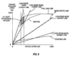
- FIG. 5 is a view illustrating a 2-1 shift permission region of a subtransmission mechanism.
- a "speed ratio" of a certain speed change mechanism is a value obtained by dividing an input rotation speed of the speed change mechanism by an output rotation speed of the speed change mechanism. Further, a “Lowest speed ratio” is a maximum speed ratio of the speed change mechanism and a “Highest speed ratio” is a minimum speed ratio of the speed change mechanism.
- FIG. 1 is a schematic diagram showing a vehicle installed with a continuously variable transmission according to an embodiment of this invention.
- the vehicle includes an engine 1 as a power source. An output rotation of the engine 1 is transmitted to drive wheels 7 via a torque converter 2, a first gear train 3, a continuously variable transmission (to be referred to simply as a "transmission 4" hereafter), a second gear train 5, and a final reduction gear 6.
- the second gear train 5 is provided with a parking mechanism 8 which locks an output shaft of the transmission 4 mechanically during parking so that the output shaft of the transmission 4 cannot rotate.
- the torque converter 2 includes a lockup clutch 2a.
- lockup clutch 2a When the lockup clutch 2a is engaged, slippage in the torque converter 2 is eliminated, leading to an improvement in a transmission efficiency of the torque converter 2.
- the vehicle is provided with an oil pump 10 that is driven using a part of the power of the engine 1, a hydraulic control circuit 11 that regulates an oil pressure from the oil pump 10 and supplies the regulated oil pressure to respective sites of the transmission 4, and a transmission controller 12 that controls the hydraulic control circuit 11.
- the transmission 4 includes a belt continuously variable speed change mechanism (to be referred to hereafter as a "variator") 20, and a subtransmission mechanism 30 provided in series with the variator 20.
- “provided in series” means that the variator 20 and the subtransmission mechanism 30 are provided in series on a power transmission path extending from the engine 1 to the drive wheels 7.
- the subtransmission mechanism 30 may be connected to an output shaft of the variator 20 directly, as in this example, or via another speed change/power transmission mechanism (a gear train, for example). Alternatively, the subtransmission mechanism 30 may be connected to a front stage (an input shaft side) of the variator 20.
- the variator 20 includes a primary pulley 21, a secondary pulley 22, and a V belt 23 wrapped around the pulleys 21, 22.
- the pulleys 21, 22 respectively include a fixed conical plate, a movable conical plate disposed relative to the fixed conical plate such that respective sheave surfaces thereof oppose each other, thereby forming a V groove, and hydraulic cylinders 23a, 23b provided on a back surface of the movable conical plate so as to displace the movable conical plate in an axial direction.
- the subtransmission mechanism 30 is a speed change mechanism having two-forward speed and single-reverse speed.
- the subtransmission mechanism 30 includes a Ravigneaux planetary gear mechanism 31 in which carriers of two planetary gears are coupled, and a plurality of frictional engagement elements (a Low brake 32, a High clutch 33, and a Rev brake 34) which are connected to a plurality of rotary elements constituting the Ravigneaux planetary gear mechanism 31 so as to modify rotation states thereof.
- a Ravigneaux planetary gear mechanism 31 in which carriers of two planetary gears are coupled
- a plurality of frictional engagement elements a Low brake 32, a High clutch 33, and a Rev brake 34
- engagement/disengagement states of the respective frictional engagement elements 32 to 34 are modified by regulating oil pressures supplied to the respective frictional engagement elements 32 to 34, the gear position of the subtransmission mechanism 30 is changed.
- the gear position of the subtransmission mechanism 30 becomes a first speed.
- the gear position of the subtransmission mechanism 30 becomes a second speed in which the speed ratio is smaller than that of the first speed.
- the Rev brake 34 is engaged and the Low brake 32 and High clutch 33 are disengaged, the gear position of the subtransmission mechanism 30 becomes the reverse speed.
- the terms "the transmission 4 is in a low speed mode” and "the transmission 4 is in a high speed mode” will be used to indicate that the gear position of the subtransmission mechanism 30 corresponds to the first speed and the second speed, respectively.
- the transmission controller 12 is constituted by a CPU 121, a memory device 122 including a RAM and a ROM, an input interface 123, an output interface 124, and a bus 125 that connects these components to each other.
- An output signal from an accelerator opening sensor 41 that detects an accelerator opening APO, which is an operating amount of an accelerator pedal, an output signal from a rotation speed sensor 42 that detects an input rotation speed of the transmission 4 ( a rotation speed of the primary pulley 21; to be referred to hereafter as a "primary rotation speed Npri"), an output signal from a vehicle speed sensor 43 that detects a vehicle speed VSP, an output signal from an oil temperature sensor 44 that detects an oil temperature TMP of the transmission 4, an output signal from an inhibitor switch 45 that detects a position of a select lever, and so on are input into the input interface 123.
- the memory device 122 stores a shift control program ( FIG. 4 ) of the transmission 4, and a shift map ( FIG. 3 ) used by the shift control program.
- the CPU 121 reads and executes the shift control program stored in the memory device 122, generates a shift control signal by implementing various types of calculation processing on the various signals input via the input interface 123, and outputs the generated shift control signal to the hydraulic control circuit 11 via the output interface 124.
- Various values used during the calculation processing executed by the CPU 121 and results of the calculation processing are stored in the memory device 122 as appropriate.
- the hydraulic control circuit 11 is constituted by a plurality of flow passages and a plurality of hydraulic control valves.
- the hydraulic control circuit 11 controls the plurality of hydraulic control valves on the basis of the shift control signal from the transmission controller 12 to switch an oil pressure supply path, regulate the oil pressure generated by the oil pump 10 to a required oil pressure, and supply the regulated oil pressure to the respective sites of the transmission 4.
- the shift of the variator 20, the change of the gear position of the subtransmission mechanism 30, and the engagement/ disengagement of the lockup clutch 2a are performed.
- FIG. 3 shows an example of the shift map stored in the memory device 122.
- the transmission controller 12 controls the variator 20 and the subtransmission mechanism 30 in accordance with operating conditions of the vehicle (in this embodiment, the vehicle speed VSP, the primary rotation speed Npri, and the accelerator opening APO) while referring to the shift map.
- operating conditions of the vehicle in this embodiment, the vehicle speed VSP, the primary rotation speed Npri, and the accelerator opening APO
- operating points of the transmission 4 are defined by the vehicle speed VSP and the primary rotation speed Npri.
- An incline of a line linking the operating point of the transmission 4 and a zero point in a lower left corner of the shift map corresponds to the speed ratio of the transmission 4 (an overall speed ratio obtained by multiplying the speed ratio of the subtransmission mechanism 30 by the speed ratio of the variator 20; to be referred to hereafter as a "through speed ratio").
- a shift line is set for each accelerator opening APO, and a shift is performed in the transmission 4 in accordance with a shift line selected according to the accelerator opening APO.
- the transmission 4 When the transmission 4 is in the low speed mode, the transmission 4 can be shifted between a low speed mode Lowest line obtained by setting the speed ratio of the variator 20 at the Lowest speed ratio and a low speed mode Highest line obtained by setting the speed ratio of the variator 20 at the Highest speed ratio. Namely, in the low speed mode, the operating point of the transmission 4 moves within an A region and a B region in the figure.
- the transmission 4 When the transmission 4 is in the high speed mode, on the other hand, the transmission 4 can be shifted between a high speed mode Lowest line obtained by setting the speed ratio of the variator 20 at the Lowest speed ratio and a high speed mode Highest line obtained by setting the speed ratio of the variator 20 at the Highest speed ratio. Namely, in the high speed mode, the operating point of the transmission 4 moves within the B region and a C region in the figure.
- the speed ratio in each gear position of the subtransmission mechanism 30 is set such that the speed ratio corresponding to the low speed mode Highest line (the low speed mode Highest speed ratio) is smaller than the speed ratio corresponding to the high speed mode Lowest line (the high speed mode Lowest speed ratio).
- a through speed ratio range of the transmission 4 that can be realized in the low speed mode partially overlaps a through speed ratio range of the transmission 4 that can be realized in the high speed mode (referred to as a "high speed mode ratio range” in the figure), and therefore, when the operating point of the transmission 4 is in the B region sandwiched between the high speed mode Lowest line and the low speed mode Highest line, the transmission 4 can select either the low speed mode or the high speed mode.
- a mode switch line at which the subtransmission mechanism 30 performs a shift is set on the shift map to overlap the low speed mode Highest line.
- the through speed ratio corresponding to the mode switch line (to be referred to hereafter as a "mode switch speed ratio mRatio") is set at an equal value to the low speed mode Highest speed ratio.
- the reason for setting the mode switch line in this manner is because an input torque input into the subtransmission mechanism 30 decreases as the speed ratio of the variator 20 decreases and thus shift shock during a shift in the subtransmission mechanism 30 can be suppressed.
- the transmission controller 12 When the operating point of the transmission 4 crosses the mode switch line, or in other words when an actual value of the through speed ratio (to be referred to hereafter as an "actual through speed ratio Ratio") passes the mode switch speed ratio mRatio, the transmission controller 12 performs a mode switch shift.
- the operation point of the transmission 4 crosses the mode switch line is expressed as “the through speed ratio of the transmission 4 passes the mode switch line”.
- the transmission controller 12 performs a shift in the subtransmission mechanism 30 and varies the speed ratio of the variator 20 in an opposite direction to a variation direction of the speed ratio of the subtransmission mechanism 30.
- the reason for causing the speed ratio of the variator 20 to vary in the opposite direction to the speed ratio variation direction of the subtransmission mechanism 30 during a mode switch shift is to ensure that a driver does not experience an unpleasant feeling due to input rotation variation caused by a step in the actual through speed ratio Ratio.
- the transmission controller 12 changes the gear position of the subtransmission mechanism 30 from the first speed to the second speed (a 1-2 shift) and varies the speed ratio of the variator 20 to the Low side.
- the transmission controller 12 changes the gear position of the subtransmission mechanism 30 from the second speed to the first speed (a 2-1 shift) and varies the speed ratio of the variator 20 to the High side.
- the transmission controller 12 allows a 2-1 shift to be performed in the subtransmission mechanism 30 only in a situation where a large driving force, for example a driving force that cannot be achieved by keeping the gear position of the subtransmission mechanism 30 at the second speed, is required, such as a situation in which the accelerator pedal is depressed sharply, thereby reducing a shift frequency of the subtransmission mechanism 30.
- a large driving force for example a driving force that cannot be achieved by keeping the gear position of the subtransmission mechanism 30 at the second speed
- the transmission 4 is shifted by shifting the variator 20 alone.
- the transmission 4 cannot be downshifted further, and therefore the driving force may be insufficient.
- the transmission controller 12 disengages the lockup clutch 2a such that the driving force is increased using a torque amplification action of the torque converter 2.
- FIG. 4 shows an example of the shift control program stored in the memory device 122 of the transmission controller 12. The specific content of the shift control executed by the transmission controller 12 will now be described with reference to FIG. 4 .
- the transmission controller 12 searches the shift map shown in FIG. 3 for a value corresponding to the current vehicle speed VSP and accelerator opening APO, and sets this value as a destination primary rotation speed DsrREV.
- the destination primary rotation speed DsrREV is a primary rotation speed to be reached at the current vehicle speed VSP and accelerator opening APO, and serves as a steady-state target value of the primary rotation speed.
- the transmission controller 12 calculates a destination through speed ratio DRatio by dividing the destination primary rotation speed DsrREV by the vehicle speed VSP and a final reduction ratio fRatio of the final reduction gear 6.
- the destination through speed ratio DRatio is a through speed ratio to be reached at the current vehicle speed VSP and accelerator opening APO, and serves as a steady-state target value of the through speed ratio.
- the transmission controller 12 determines whether or not the shift in the transmission 4 is a downshift and whether or not a 2-1 shift is permitted in the subtransmission mechanism 30.
- the transmission controller 12 determines whether or not the shift in the transmission 4 is a downshift by comparing the destination through speed ratio DRatio with an actual through speed ratio Ratio.
- the actual through speed ratio Ratio is calculated whenever required on the basis of the current vehicle speed VSP and primary rotation speed Npri (likewise hereafter).
- the transmission controller 12 determines that the shift in the transmission 4 is a downshift, and when the destination through speed ratio DRatio is equal to or smaller than the actual through speed ratio Ratio, the transmission controller 12 determines that the shift is an upshift.
- the transmission controller 12 determines whether or not a 2-1 shift is permitted in the subtransmission mechanism 30 on the basis of the accelerator opening APO, the vehicle speed VSP, and the destination through speed ratio DRatio.
- the transmission controller 12 permits a 2-1 shift in the subtransmission mechanism 30 only when a large driving force that cannot be achieved by keeping the gear position of the subtransmission mechanism 30 at the second speed is required.
- a region (to be referred to hereafter as a "2-1 shift permission region") in which a 2-1 shift is permitted in the subtransmission mechanism 30 is set in advance on the shift map.
- a 2-1 shift is permitted in the subtransmission mechanism 30.
- the operating point here is not an actual operating point but an operating point reached once the shift in the transmission 4 is complete.
- an incline of a line linking the operating point and a zero point in a lower left corner of the shift map corresponds to the destination through speed ratio DRatio.
- a predetermined vehicle speed range for example, a medium vehicle speed region of 30km/h to 45km/h.
- the 2-1 shift permission region is disposed on a Low side (the upper left side of the figure) of a high speed mode Lowest line.
- a 2-1 shift is permitted in the subtransmission mechanism 30 when the destination through speed ratio DRatio is larger than the high speed mode Lowest speed ratio.
- the reason for this is that when the destination through speed ratio DRatio is smaller than the high speed mode Lowest speed ratio, the destination through speed ratio DRatio can be achieved, or in other words the required driving force can be generated, by shifting the variator 20 alone, i.e. without performing a 2-1 shift in the subtransmission mechanism 30.
- the 2-1 shift permission condition described here is merely an example, and the condition is not limited thereto.
- an increase in the oil temperature TMP may be promoted by permitting a 2-1 shift in the subtransmission mechanism 30 and performing the 2-1 shift actively, thereby keeping the primary rotation speed Npri high.
- the transmission controller 12 does not permit a 2-1 shift in the subtransmission mechanism 30.
- the transmission controller 12 sets a target through speed ratio RatioO for varying the actual through speed ratio Ratio from the value thereof at the start of the shift to the destination through speed ratio DRatio at a predetermined transient response.
- the target through speed ratio RatioO is a transient target value of the through speed ratio.
- the predetermined transient response is a first order lag response, for example, which is set such that the target through speed ratio Ratio0 gradually approaches the destination through speed ratio DRatio.
- the transmission controller 12 controls the actual through speed ratio Ratio to the target through speed ratio Ratio0 More specifically, the transmission controller 12 calculates a target speed ratio vRatioO of the variator 20 by dividing the target through speed ratio RatioO by the speed ratio of the subtransmission mechanism 30, and controls the variator 20 such that an actual speed ratio vRatio of the variator 20 becomes the target speed ratio vRatioO. As a result, the actual through speed ratio Ratio follows the destination through speed ratio DRatio at the predetermined transient response.
- the transmission controller 12 determines whether or not the actual through speed ratio Ratio has passed the mode switch line (the mode switch speed ratio mRatio). When an affirmative determination is made, the processing advances to S17, and when a negative determination is made, the processing advances to S18.
- the transmission controller 12 performs a mode switch shift.
- the transmission controller 12 performs a shift in the subtransmission mechanism 30 (when the current gear position is the first speed, a 1-2 shift and when the current gear position is the second speed, a 2-1 shift), and varies the actual speed ratio vRatio of the variator 20 in the opposite direction to the speed ratio variation direction of the subtransmission mechanism 30 to ensure that a step does not occur in the actual through speed ratio Ratio on either side of the mode switch shift.
- the transmission controller 12 determines whether or not the shift is complete. More specifically, the transmission controller 12 determines that the shift is complete when a deviation between the actual through speed ratio Ratio and the destination through speed ratio DRatio is smaller than a predetermined value. When it is determined that the shift is complete, the processing is terminated, and when it is determined that the shift is not complete, the processing of S14 to S18 is repeated until it is determined that the shift is complete.
- the transmission controller 12 calculates the target through speed ratio Ratio0 on the basis of the destination through speed ratio DRatio and controls the variator 20 on the basis thereof in S20 and S21, similarly to S14 and S15.
- the transmission controller 12 does not determine whether or not the actual speed ratio Ratio of the transmission 4 has passed the mode switch line, as in S16, and performs a shift in the variator 20 alone even if the actual speed ratio Ratio of the transmission 4 has passed the mode switch line.
- the transmission controller 12 determines whether or not a state in which the actual speed ratio vRatio of the variator 20 corresponds to the Lowest speed ratio has continued for a predetermined time or more. When it is determined that this state has continued for the predetermined time or more, the transmission controller 12 disengages the lockup clutch 2a in S24 such that the driving force is increased by the torque amplification action of the torque converter 2.
- the transmission controller 12 determines whether or not the shift is complete. When the shift is determined to be complete, the processing is terminated, and when the shift is not complete, the processing of S20 to S22 is repeated.
- a 1-2 shift and a 2-1 shift are both performed in the subtransmission mechanism 30 when the actual through speed ratio Ratio passes the mode switch line (the mode switch speed ratio mRatio) (S17).
- a 2-1 shift is permitted in the subtransmission mechanism 30 only in a situation where a large driving force is required, such as when the accelerator pedal is depressed sharply ( FIG. 5 ), and therefore the frequency with which a 2-1 shift follows a 1-2 shift is reduced.
- problems occurring when shifts are performed repeatedly in the subtransmission mechanism 30, such as a reduction in drivability due to repeated occurrence of shift shock and a reduction in the durability of the frictional engagement elements (the Low brake 32, High clutch 33, and Rev brake 34) constituting the subtransmission mechanism 30 can be prevented.
- the determination as to whether driving force is required is made taking into consideration not only the magnitude of the accelerator opening APO but also the variation speed thereof, the vehicle speed VSP, and the destination through speed ratio DRatio. Thus, the determination as to whether driving force is required can be made appropriately.
- the transmission 4 is downshifted by shifting the variator 20 alone such that further downshifts become impossible at the point where the speed ratio of the variator 20 reaches the Lowest speed ratio, and as a result, the driving force may be insufficient.
- the lockup clutch 2a is disengaged when this state has continued for a predetermined time (S22 ⁇ S24) so that the driving force can be increased by the torque amplification action of the torque converter 2, and therefore a driving force deficiency can be prevented.
- the mode switch line is set to overlap the low speed mode Highest line, but the mode switch line may be set to overlap the high speed mode Lowest line or set between the high speed mode Lowest line and the low speed mode Highest line.
- the mode switch line may be comprised of polygonal line similar to a shift line for a conventional step automatic transmission.
- the subtransmission mechanism 30 is a speed change mechanism having the first speed and second speed gear positions as forward gear positions, but the subtransmission mechanism 30 may be a speed change mechanism having three or more gear positions as forward gear positions.
- the subtransmission mechanism 30 is formed using a Ravigneaux planetary gear mechanism, but is not limited to this constitution.
- the subtransmission mechanism 30 may be constituted by a combination of a normal planetary gear mechanism and frictional engagement elements, or by a plurality of power transmission paths formed from a plurality of gear trains having different speed ratios, and frictional engagement elements for switching the power transmission paths.
- V belt 23 may be comprised of a metal ring and a plurality of metal elements, but the V belt 23 may be comprised of an endless chain.
- belt in claims covers various types of belt which can be used for transmitting rotation between pulleys in a continuously variable transmission.
- hydraulic cylinders 23a, 23b are provided as actuators for displacing the movable conical plates of the pulleys 21, 22 in the axial direction, but the actuators may be driven electrically rather than hydraulically.
- the power source is comprised of the engine 1, but an electric motor or a combination of an engine and an electric motor may be used as the power source.
Applications Claiming Priority (1)
| Application Number | Priority Date | Filing Date | Title |
|---|---|---|---|
| JP2009079677A JP4923080B2 (ja) | 2009-03-27 | 2009-03-27 | 無段変速機及びその制御方法 |
Publications (2)
| Publication Number | Publication Date |
|---|---|
| EP2233794A1 EP2233794A1 (en) | 2010-09-29 |
| EP2233794B1 true EP2233794B1 (en) | 2011-06-22 |
Family
ID=42310661
Family Applications (1)
| Application Number | Title | Priority Date | Filing Date |
|---|---|---|---|
| EP10002299A Active EP2233794B1 (en) | 2009-03-27 | 2010-03-05 | Continuously variable transmission and control method thereof |
Country Status (6)
| Country | Link |
|---|---|
| US (1) | US8712649B2 (zh) |
| EP (1) | EP2233794B1 (zh) |
| JP (1) | JP4923080B2 (zh) |
| KR (2) | KR20100108276A (zh) |
| CN (2) | CN101846182B (zh) |
| AT (1) | ATE514021T1 (zh) |
Families Citing this family (20)
| Publication number | Priority date | Publication date | Assignee | Title |
|---|---|---|---|---|
| JP4660584B2 (ja) | 2008-09-25 | 2011-03-30 | ジヤトコ株式会社 | 無段変速機及びその変速制御方法 |
| JP4914467B2 (ja) | 2009-07-17 | 2012-04-11 | ジヤトコ株式会社 | 無段変速機及びその制御方法 |
| JP5080627B2 (ja) * | 2010-09-30 | 2012-11-21 | ジヤトコ株式会社 | 無段変速機及び変速制御方法 |
| JP5542607B2 (ja) * | 2010-10-06 | 2014-07-09 | ジヤトコ株式会社 | コーストストップ車両及びコーストストップ方法 |
| JP5691602B2 (ja) * | 2011-02-15 | 2015-04-01 | 日産自動車株式会社 | 無段変速機の変速制御装置及び制御方法 |
| EP2792913A4 (en) * | 2011-12-12 | 2016-06-01 | Jatco Ltd | CONTINUOUS GEARBOX AND METHOD FOR ITS CONTROL |
| CN104641155B (zh) * | 2012-09-27 | 2016-09-21 | 加特可株式会社 | 无级变速器及其控制方法 |
| WO2014061601A1 (ja) * | 2012-10-15 | 2014-04-24 | ジヤトコ株式会社 | 無段変速機及びその制御方法 |
| JP5852554B2 (ja) * | 2012-12-21 | 2016-02-03 | 本田技研工業株式会社 | 自動変速機の油圧供給装置 |
| JP6006884B2 (ja) | 2013-09-30 | 2016-10-12 | ジヤトコ株式会社 | 油圧スイッチの故障判定装置 |
| KR101828724B1 (ko) * | 2013-10-08 | 2018-02-12 | 쟈트코 가부시키가이샤 | 부변속기를 구비한 무단 변속기의 제어 장치 |
| JP6014634B2 (ja) * | 2014-08-04 | 2016-10-25 | ジヤトコ株式会社 | 変速機、及びその制御方法 |
| US10436312B2 (en) | 2015-02-06 | 2019-10-08 | Nissan Motor Co., Ltd. | Control system for automatic transmission |
| US10605358B2 (en) * | 2015-06-23 | 2020-03-31 | Jatco Ltd | Transmission and control method for transmission |
| KR101992072B1 (ko) * | 2015-08-24 | 2019-06-21 | 쟈트코 가부시키가이샤 | 차량의 로크업 클러치 제어 장치 및 로크업 클러치 제어 방법 |
| EP3426947A1 (en) * | 2016-03-10 | 2019-01-16 | Punch Powertrain N.V. | Continuously variable transmission and method for transferring torque |
| EP3258139B1 (en) | 2016-06-14 | 2021-04-21 | Perkins Engines Company Limited | A method of reducing output torque deficits during launch of a continuously variable transmission |
| JP6926973B2 (ja) * | 2017-11-13 | 2021-08-25 | トヨタ自動車株式会社 | 車両用動力伝達装置の制御装置 |
| JP6922757B2 (ja) * | 2018-01-24 | 2021-08-18 | トヨタ自動車株式会社 | 自動変速機の制御装置 |
| KR20210144457A (ko) | 2020-05-22 | 2021-11-30 | 박대웅 | 세척이 가능한 빨대 |
Family Cites Families (43)
| Publication number | Priority date | Publication date | Assignee | Title |
|---|---|---|---|---|
| NL189731C (nl) * | 1982-02-08 | 1993-07-01 | Honda Motor Co Ltd | Variabele transmissie. |
| JPS6037455A (ja) * | 1983-08-10 | 1985-02-26 | Toyota Motor Corp | 車両用無段変速装置 |
| JPS6141071A (ja) | 1984-08-03 | 1986-02-27 | Toyota Motor Corp | 無段変速機付き動力伝達装置の油圧制御装置 |
| US4672863A (en) * | 1985-04-17 | 1987-06-16 | Toyota Jidosha Kabushiki Kaisha | Method and apparatus for controlling power transmission system in an automotive vehicle |
| US4793217A (en) | 1985-09-17 | 1988-12-27 | Toyota Jidosha Kabushiki Kaisha | Method and apparatus for controlling power transmitting system for automotive vehicle, including continuously variable transmission and auxiliary transmission |
| JP2759938B2 (ja) * | 1986-02-04 | 1998-05-28 | トヨタ自動車株式会社 | 車両用変速機の制御方法 |
| JPH07102792B2 (ja) * | 1986-11-13 | 1995-11-08 | トヨタ自動車株式会社 | 副変速機および無段変速機を備えた車両用変速機の制御方法 |
| JPH04307165A (ja) | 1991-04-01 | 1992-10-29 | Toyota Motor Corp | 車両用無段変速機の制御装置 |
| JPH0579554A (ja) * | 1991-06-27 | 1993-03-30 | Toyota Motor Corp | 車両用無段変速機の制御装置 |
| JPH08178043A (ja) | 1994-12-28 | 1996-07-12 | Aisin Seiki Co Ltd | 変速機制御装置 |
| JP3358435B2 (ja) | 1996-04-12 | 2002-12-16 | 日産自動車株式会社 | 無段自動変速機の変速制御装置 |
| JP3520179B2 (ja) * | 1997-04-25 | 2004-04-19 | 株式会社日立ユニシアオートモティブ | 自動変速機の変速制御装置 |
| JP3527391B2 (ja) | 1997-07-30 | 2004-05-17 | 日産自動車株式会社 | 車両用無段変速機の変速制御方法 |
| JP3580993B2 (ja) * | 1997-10-01 | 2004-10-27 | 本田技研工業株式会社 | ロックアップ制御装置 |
| DE19941009A1 (de) * | 1999-08-28 | 2001-03-01 | Volkswagen Ag | Verfahren zur Steuerung der Schaltungen eines Kraftfahrzeugsgetriebes |
| DE19950053A1 (de) | 1999-10-16 | 2001-04-19 | Zahnradfabrik Friedrichshafen | Stufenlos verstellbares Fahrzeuggetriebe |
| JP2001330144A (ja) | 2000-05-23 | 2001-11-30 | Toyota Motor Corp | 自動変速機の制御装置 |
| JP3942005B2 (ja) | 2000-09-29 | 2007-07-11 | ジヤトコ株式会社 | 無段変速機の変速制御装置 |
| KR100373026B1 (ko) * | 2000-10-17 | 2003-02-25 | 현대자동차주식회사 | 자동 변속기의 변속 제어 시스템 및 그 방법 |
| US6932739B2 (en) | 2001-12-25 | 2005-08-23 | Nsk Ltd. | Continuously variable transmission apparatus |
| JP3794483B2 (ja) | 2002-06-05 | 2006-07-05 | 本田技研工業株式会社 | 車両用無段変速機の制御装置 |
| JP4378991B2 (ja) | 2003-04-10 | 2009-12-09 | 日本精工株式会社 | 無段変速装置 |
| JP4069054B2 (ja) | 2003-10-16 | 2008-03-26 | 本田技研工業株式会社 | 動力伝達装置の油圧制御装置 |
| JP2006112536A (ja) | 2004-10-15 | 2006-04-27 | Nissan Motor Co Ltd | 自動変速機の変速制御装置 |
| JP4839647B2 (ja) | 2005-03-22 | 2011-12-21 | 日産自動車株式会社 | 自動変速機の同調変速制御装置 |
| JP4483819B2 (ja) | 2005-04-28 | 2010-06-16 | 株式会社豊田中央研究所 | 動力伝達システム |
| JP2007092665A (ja) * | 2005-09-29 | 2007-04-12 | Nissan Motor Co Ltd | 車両の変速装置 |
| JP4052329B2 (ja) | 2005-10-26 | 2008-02-27 | トヨタ自動車株式会社 | 自動変速機の変速制御装置 |
| JP2007157106A (ja) * | 2005-12-01 | 2007-06-21 | Korea Electronics Telecommun | コンポーネント基盤の衛星モデリングによる衛星シミュレーションシステム |
| JP4123289B2 (ja) | 2006-07-11 | 2008-07-23 | トヨタ自動車株式会社 | 無段変速機の変速制御装置 |
| DE102006039608A1 (de) | 2006-08-24 | 2008-04-10 | Rolls-Royce Deutschland Ltd & Co Kg | Anordnung zur Energieentnahme bei einem Zwei-Wellen-Triebwerk |
| JP4400617B2 (ja) * | 2006-12-15 | 2010-01-20 | トヨタ自動車株式会社 | パワートレーンの制御装置、制御方法、その方法を実現させるプログラムおよびそのプログラムを記録した記録媒体 |
| US8204659B2 (en) * | 2007-03-12 | 2012-06-19 | Nissan Motor Co., Ltd. | Engine start control system for hybrid vehicle |
| JP5161523B2 (ja) * | 2007-03-30 | 2013-03-13 | ヤマハ発動機株式会社 | 鞍乗型車両、パワーユニットおよび無段変速機 |
| US8000863B2 (en) * | 2007-05-31 | 2011-08-16 | Caterpillar Inc. | Open-loop torque control with closed-loop feedback |
| JP4930261B2 (ja) | 2007-08-06 | 2012-05-16 | トヨタ自動車株式会社 | 車両用動力伝達装置の制御装置 |
| US7789795B2 (en) | 2007-10-17 | 2010-09-07 | Eaton Corporation | Method for controlling a vehicle powertrain having step ratio gearing and a continuously variable transmission to achieve optimum engine fuel economy |
| US8187145B2 (en) * | 2007-10-25 | 2012-05-29 | GM Global Technology Operations LLC | Method and apparatus for clutch torque control in mode and fixed gear for a hybrid powertrain system |
| US8214093B2 (en) * | 2007-11-04 | 2012-07-03 | GM Global Technology Operations LLC | Method and apparatus to prioritize transmission output torque and input acceleration for a hybrid powertrain system |
| CN102317146B (zh) * | 2007-12-21 | 2015-11-25 | 福博科知识产权有限责任公司 | 自动传动装置及用于其的方法 |
| JP2009156436A (ja) * | 2007-12-27 | 2009-07-16 | Aisin Aw Co Ltd | 自動変速機の制御装置 |
| JP4923079B2 (ja) | 2009-03-27 | 2012-04-25 | ジヤトコ株式会社 | 無段変速機及びその制御方法 |
| JP4914467B2 (ja) | 2009-07-17 | 2012-04-11 | ジヤトコ株式会社 | 無段変速機及びその制御方法 |
-
2009
- 2009-03-27 JP JP2009079677A patent/JP4923080B2/ja active Active
-
2010
- 2010-03-05 AT AT10002299T patent/ATE514021T1/de not_active IP Right Cessation
- 2010-03-05 EP EP10002299A patent/EP2233794B1/en active Active
- 2010-03-19 US US12/727,506 patent/US8712649B2/en active Active
- 2010-03-25 CN CN201010147530.0A patent/CN101846182B/zh active Active
- 2010-03-25 CN CN201410006178.7A patent/CN103697155B/zh active Active
- 2010-03-26 KR KR1020100027057A patent/KR20100108276A/ko active Application Filing
-
2016
- 2016-12-12 KR KR1020160168489A patent/KR101775848B1/ko active IP Right Grant
Also Published As
| Publication number | Publication date |
|---|---|
| CN103697155B (zh) | 2019-01-18 |
| US20100248875A1 (en) | 2010-09-30 |
| EP2233794A1 (en) | 2010-09-29 |
| ATE514021T1 (de) | 2011-07-15 |
| KR20160146621A (ko) | 2016-12-21 |
| KR101775848B1 (ko) | 2017-09-06 |
| CN101846182B (zh) | 2014-07-23 |
| JP4923080B2 (ja) | 2012-04-25 |
| KR20100108276A (ko) | 2010-10-06 |
| JP2010230117A (ja) | 2010-10-14 |
| CN103697155A (zh) | 2014-04-02 |
| US8712649B2 (en) | 2014-04-29 |
| CN101846182A (zh) | 2010-09-29 |
Similar Documents
| Publication | Publication Date | Title |
|---|---|---|
| EP2233794B1 (en) | Continuously variable transmission and control method thereof | |
| EP2233795B1 (en) | Continuously variable transmission and control method thereof | |
| EP2169278B1 (en) | Continuously variable transmission and control method thereof | |
| EP2233796B1 (en) | Continuously variable transmission and control method thereof | |
| US8241178B2 (en) | Continuously variable transmission and control method thereof | |
| EP2169279B1 (en) | Continuously variable transmission and control method thereof | |
| EP2169277B1 (en) | Continuously variable transmission and control method thereof | |
| US8585542B2 (en) | Control of and control method for vehicle continuously variable transmission | |
| EP2275713B1 (en) | Shift control of continuously variable transmission | |
| EP2428710B1 (en) | Continuously variable transmission and control method therefore | |
| EP2275710B1 (en) | Control device of and control method for vehicle continuously variable transmission | |
| KR101633592B1 (ko) | 무단 변속기 및 그 제어 방법 |
Legal Events
| Date | Code | Title | Description |
|---|---|---|---|
| PUAI | Public reference made under article 153(3) epc to a published international application that has entered the european phase |
Free format text: ORIGINAL CODE: 0009012 |
|
| AK | Designated contracting states |
Kind code of ref document: A1 Designated state(s): AT BE BG CH CY CZ DE DK EE ES FI FR GB GR HR HU IE IS IT LI LT LU LV MC MK MT NL NO PL PT RO SE SI SK SM TR |
|
| AX | Request for extension of the european patent |
Extension state: AL BA ME RS |
|
| 17P | Request for examination filed |
Effective date: 20100929 |
|
| GRAP | Despatch of communication of intention to grant a patent |
Free format text: ORIGINAL CODE: EPIDOSNIGR1 |
|
| RIC1 | Information provided on ipc code assigned before grant |
Ipc: F16H 37/02 20060101ALN20101229BHEP Ipc: F16H 61/70 20060101ALI20101229BHEP Ipc: F16H 61/662 20060101AFI20101229BHEP |
|
| GRAS | Grant fee paid |
Free format text: ORIGINAL CODE: EPIDOSNIGR3 |
|
| GRAA | (expected) grant |
Free format text: ORIGINAL CODE: 0009210 |
|
| AK | Designated contracting states |
Kind code of ref document: B1 Designated state(s): AT BE BG CH CY CZ DE DK EE ES FI FR GB GR HR HU IE IS IT LI LT LU LV MC MK MT NL NO PL PT RO SE SI SK SM TR |
|
| REG | Reference to a national code |
Ref country code: GB Ref legal event code: FG4D |
|
| REG | Reference to a national code |
Ref country code: CH Ref legal event code: EP |
|
| REG | Reference to a national code |
Ref country code: IE Ref legal event code: FG4D |
|
| REG | Reference to a national code |
Ref country code: DE Ref legal event code: R096 Ref document number: 602010000066 Country of ref document: DE Effective date: 20110804 |
|
| REG | Reference to a national code |
Ref country code: NL Ref legal event code: VDEP Effective date: 20110622 |
|
| PG25 | Lapsed in a contracting state [announced via postgrant information from national office to epo] |
Ref country code: LT Free format text: LAPSE BECAUSE OF FAILURE TO SUBMIT A TRANSLATION OF THE DESCRIPTION OR TO PAY THE FEE WITHIN THE PRESCRIBED TIME-LIMIT Effective date: 20110622 Ref country code: SE Free format text: LAPSE BECAUSE OF FAILURE TO SUBMIT A TRANSLATION OF THE DESCRIPTION OR TO PAY THE FEE WITHIN THE PRESCRIBED TIME-LIMIT Effective date: 20110622 Ref country code: HR Free format text: LAPSE BECAUSE OF FAILURE TO SUBMIT A TRANSLATION OF THE DESCRIPTION OR TO PAY THE FEE WITHIN THE PRESCRIBED TIME-LIMIT Effective date: 20110622 Ref country code: NO Free format text: LAPSE BECAUSE OF FAILURE TO SUBMIT A TRANSLATION OF THE DESCRIPTION OR TO PAY THE FEE WITHIN THE PRESCRIBED TIME-LIMIT Effective date: 20110922 |
|
| PG25 | Lapsed in a contracting state [announced via postgrant information from national office to epo] |
Ref country code: GR Free format text: LAPSE BECAUSE OF FAILURE TO SUBMIT A TRANSLATION OF THE DESCRIPTION OR TO PAY THE FEE WITHIN THE PRESCRIBED TIME-LIMIT Effective date: 20110923 Ref country code: SI Free format text: LAPSE BECAUSE OF FAILURE TO SUBMIT A TRANSLATION OF THE DESCRIPTION OR TO PAY THE FEE WITHIN THE PRESCRIBED TIME-LIMIT Effective date: 20110622 Ref country code: LV Free format text: LAPSE BECAUSE OF FAILURE TO SUBMIT A TRANSLATION OF THE DESCRIPTION OR TO PAY THE FEE WITHIN THE PRESCRIBED TIME-LIMIT Effective date: 20110622 Ref country code: FI Free format text: LAPSE BECAUSE OF FAILURE TO SUBMIT A TRANSLATION OF THE DESCRIPTION OR TO PAY THE FEE WITHIN THE PRESCRIBED TIME-LIMIT Effective date: 20110622 Ref country code: CY Free format text: LAPSE BECAUSE OF FAILURE TO SUBMIT A TRANSLATION OF THE DESCRIPTION OR TO PAY THE FEE WITHIN THE PRESCRIBED TIME-LIMIT Effective date: 20110622 Ref country code: AT Free format text: LAPSE BECAUSE OF FAILURE TO SUBMIT A TRANSLATION OF THE DESCRIPTION OR TO PAY THE FEE WITHIN THE PRESCRIBED TIME-LIMIT Effective date: 20110622 |
|
| REG | Reference to a national code |
Ref country code: GB Ref legal event code: 732E Free format text: REGISTERED BETWEEN 20111103 AND 20111109 |
|
| PG25 | Lapsed in a contracting state [announced via postgrant information from national office to epo] |
Ref country code: BE Free format text: LAPSE BECAUSE OF FAILURE TO SUBMIT A TRANSLATION OF THE DESCRIPTION OR TO PAY THE FEE WITHIN THE PRESCRIBED TIME-LIMIT Effective date: 20110622 Ref country code: NL Free format text: LAPSE BECAUSE OF FAILURE TO SUBMIT A TRANSLATION OF THE DESCRIPTION OR TO PAY THE FEE WITHIN THE PRESCRIBED TIME-LIMIT Effective date: 20110622 |
|
| PG25 | Lapsed in a contracting state [announced via postgrant information from national office to epo] |
Ref country code: EE Free format text: LAPSE BECAUSE OF FAILURE TO SUBMIT A TRANSLATION OF THE DESCRIPTION OR TO PAY THE FEE WITHIN THE PRESCRIBED TIME-LIMIT Effective date: 20110622 Ref country code: CZ Free format text: LAPSE BECAUSE OF FAILURE TO SUBMIT A TRANSLATION OF THE DESCRIPTION OR TO PAY THE FEE WITHIN THE PRESCRIBED TIME-LIMIT Effective date: 20110622 Ref country code: PT Free format text: LAPSE BECAUSE OF FAILURE TO SUBMIT A TRANSLATION OF THE DESCRIPTION OR TO PAY THE FEE WITHIN THE PRESCRIBED TIME-LIMIT Effective date: 20111024 Ref country code: IS Free format text: LAPSE BECAUSE OF FAILURE TO SUBMIT A TRANSLATION OF THE DESCRIPTION OR TO PAY THE FEE WITHIN THE PRESCRIBED TIME-LIMIT Effective date: 20111022 |
|
| PG25 | Lapsed in a contracting state [announced via postgrant information from national office to epo] |
Ref country code: SK Free format text: LAPSE BECAUSE OF FAILURE TO SUBMIT A TRANSLATION OF THE DESCRIPTION OR TO PAY THE FEE WITHIN THE PRESCRIBED TIME-LIMIT Effective date: 20110622 Ref country code: PL Free format text: LAPSE BECAUSE OF FAILURE TO SUBMIT A TRANSLATION OF THE DESCRIPTION OR TO PAY THE FEE WITHIN THE PRESCRIBED TIME-LIMIT Effective date: 20110622 |
|
| PLBE | No opposition filed within time limit |
Free format text: ORIGINAL CODE: 0009261 |
|
| STAA | Information on the status of an ep patent application or granted ep patent |
Free format text: STATUS: NO OPPOSITION FILED WITHIN TIME LIMIT |
|
| 26N | No opposition filed |
Effective date: 20120323 |
|
| PG25 | Lapsed in a contracting state [announced via postgrant information from national office to epo] |
Ref country code: IT Free format text: LAPSE BECAUSE OF FAILURE TO SUBMIT A TRANSLATION OF THE DESCRIPTION OR TO PAY THE FEE WITHIN THE PRESCRIBED TIME-LIMIT Effective date: 20110622 |
|
| PG25 | Lapsed in a contracting state [announced via postgrant information from national office to epo] |
Ref country code: DK Free format text: LAPSE BECAUSE OF FAILURE TO SUBMIT A TRANSLATION OF THE DESCRIPTION OR TO PAY THE FEE WITHIN THE PRESCRIBED TIME-LIMIT Effective date: 20110622 |
|
| REG | Reference to a national code |
Ref country code: DE Ref legal event code: R097 Ref document number: 602010000066 Country of ref document: DE Effective date: 20120323 |
|
| PG25 | Lapsed in a contracting state [announced via postgrant information from national office to epo] |
Ref country code: MC Free format text: LAPSE BECAUSE OF NON-PAYMENT OF DUE FEES Effective date: 20120331 |
|
| REG | Reference to a national code |
Ref country code: IE Ref legal event code: MM4A |
|
| PG25 | Lapsed in a contracting state [announced via postgrant information from national office to epo] |
Ref country code: IE Free format text: LAPSE BECAUSE OF NON-PAYMENT OF DUE FEES Effective date: 20120305 |
|
| PG25 | Lapsed in a contracting state [announced via postgrant information from national office to epo] |
Ref country code: MK Free format text: LAPSE BECAUSE OF FAILURE TO SUBMIT A TRANSLATION OF THE DESCRIPTION OR TO PAY THE FEE WITHIN THE PRESCRIBED TIME-LIMIT Effective date: 20110622 |
|
| PG25 | Lapsed in a contracting state [announced via postgrant information from national office to epo] |
Ref country code: ES Free format text: LAPSE BECAUSE OF FAILURE TO SUBMIT A TRANSLATION OF THE DESCRIPTION OR TO PAY THE FEE WITHIN THE PRESCRIBED TIME-LIMIT Effective date: 20111003 |
|
| PG25 | Lapsed in a contracting state [announced via postgrant information from national office to epo] |
Ref country code: BG Free format text: LAPSE BECAUSE OF FAILURE TO SUBMIT A TRANSLATION OF THE DESCRIPTION OR TO PAY THE FEE WITHIN THE PRESCRIBED TIME-LIMIT Effective date: 20110922 |
|
| PG25 | Lapsed in a contracting state [announced via postgrant information from national office to epo] |
Ref country code: MT Free format text: LAPSE BECAUSE OF FAILURE TO SUBMIT A TRANSLATION OF THE DESCRIPTION OR TO PAY THE FEE WITHIN THE PRESCRIBED TIME-LIMIT Effective date: 20110622 |
|
| PG25 | Lapsed in a contracting state [announced via postgrant information from national office to epo] |
Ref country code: TR Free format text: LAPSE BECAUSE OF FAILURE TO SUBMIT A TRANSLATION OF THE DESCRIPTION OR TO PAY THE FEE WITHIN THE PRESCRIBED TIME-LIMIT Effective date: 20110622 |
|
| PG25 | Lapsed in a contracting state [announced via postgrant information from national office to epo] |
Ref country code: LU Free format text: LAPSE BECAUSE OF NON-PAYMENT OF DUE FEES Effective date: 20120305 Ref country code: SM Free format text: LAPSE BECAUSE OF FAILURE TO SUBMIT A TRANSLATION OF THE DESCRIPTION OR TO PAY THE FEE WITHIN THE PRESCRIBED TIME-LIMIT Effective date: 20110622 |
|
| PG25 | Lapsed in a contracting state [announced via postgrant information from national office to epo] |
Ref country code: HU Free format text: LAPSE BECAUSE OF FAILURE TO SUBMIT A TRANSLATION OF THE DESCRIPTION OR TO PAY THE FEE WITHIN THE PRESCRIBED TIME-LIMIT Effective date: 20100305 |
|
| REG | Reference to a national code |
Ref country code: CH Ref legal event code: PL |
|
| PG25 | Lapsed in a contracting state [announced via postgrant information from national office to epo] |
Ref country code: CH Free format text: LAPSE BECAUSE OF NON-PAYMENT OF DUE FEES Effective date: 20140331 Ref country code: LI Free format text: LAPSE BECAUSE OF NON-PAYMENT OF DUE FEES Effective date: 20140331 |
|
| REG | Reference to a national code |
Ref country code: FR Ref legal event code: PLFP Year of fee payment: 7 |
|
| REG | Reference to a national code |
Ref country code: FR Ref legal event code: PLFP Year of fee payment: 8 |
|
| REG | Reference to a national code |
Ref country code: FR Ref legal event code: PLFP Year of fee payment: 9 |
|
| PGFP | Annual fee paid to national office [announced via postgrant information from national office to epo] |
Ref country code: FR Payment date: 20230208 Year of fee payment: 14 |
|
| PGFP | Annual fee paid to national office [announced via postgrant information from national office to epo] |
Ref country code: DE Payment date: 20240130 Year of fee payment: 15 Ref country code: GB Payment date: 20240220 Year of fee payment: 15 |