EP2208638A2 - Verbesserter Autositz - Google Patents
Verbesserter Autositz Download PDFInfo
- Publication number
- EP2208638A2 EP2208638A2 EP10150996A EP10150996A EP2208638A2 EP 2208638 A2 EP2208638 A2 EP 2208638A2 EP 10150996 A EP10150996 A EP 10150996A EP 10150996 A EP10150996 A EP 10150996A EP 2208638 A2 EP2208638 A2 EP 2208638A2
- Authority
- EP
- European Patent Office
- Prior art keywords
- support section
- user
- composite reinforcement
- bucket seat
- seat
- Prior art date
- Legal status (The legal status is an assumption and is not a legal conclusion. Google has not performed a legal analysis and makes no representation as to the accuracy of the status listed.)
- Granted
Links
Images



Classifications
-
- B—PERFORMING OPERATIONS; TRANSPORTING
- B60—VEHICLES IN GENERAL
- B60N—SEATS SPECIALLY ADAPTED FOR VEHICLES; VEHICLE PASSENGER ACCOMMODATION NOT OTHERWISE PROVIDED FOR
- B60N2/00—Seats specially adapted for vehicles; Arrangement or mounting of seats in vehicles
- B60N2/90—Details or parts not otherwise provided for
- B60N2/986—Side-rests
- B60N2/99—Side-rests adjustable
-
- B—PERFORMING OPERATIONS; TRANSPORTING
- B60—VEHICLES IN GENERAL
- B60N—SEATS SPECIALLY ADAPTED FOR VEHICLES; VEHICLE PASSENGER ACCOMMODATION NOT OTHERWISE PROVIDED FOR
- B60N2/00—Seats specially adapted for vehicles; Arrangement or mounting of seats in vehicles
- B60N2/24—Seats specially adapted for vehicles; Arrangement or mounting of seats in vehicles for particular purposes or particular vehicles
-
- B—PERFORMING OPERATIONS; TRANSPORTING
- B60—VEHICLES IN GENERAL
- B60N—SEATS SPECIALLY ADAPTED FOR VEHICLES; VEHICLE PASSENGER ACCOMMODATION NOT OTHERWISE PROVIDED FOR
- B60N2/00—Seats specially adapted for vehicles; Arrangement or mounting of seats in vehicles
- B60N2/68—Seat frames
- B60N2/686—Panel like structures
-
- B—PERFORMING OPERATIONS; TRANSPORTING
- B60—VEHICLES IN GENERAL
- B60N—SEATS SPECIALLY ADAPTED FOR VEHICLES; VEHICLE PASSENGER ACCOMMODATION NOT OTHERWISE PROVIDED FOR
- B60N2/00—Seats specially adapted for vehicles; Arrangement or mounting of seats in vehicles
- B60N2/80—Head-rests
- B60N2/885—Head-rests provided with side-rests
-
- B—PERFORMING OPERATIONS; TRANSPORTING
- B60—VEHICLES IN GENERAL
- B60N—SEATS SPECIALLY ADAPTED FOR VEHICLES; VEHICLE PASSENGER ACCOMMODATION NOT OTHERWISE PROVIDED FOR
- B60N2/00—Seats specially adapted for vehicles; Arrangement or mounting of seats in vehicles
- B60N2/90—Details or parts not otherwise provided for
- B60N2/986—Side-rests
-
- Y—GENERAL TAGGING OF NEW TECHNOLOGICAL DEVELOPMENTS; GENERAL TAGGING OF CROSS-SECTIONAL TECHNOLOGIES SPANNING OVER SEVERAL SECTIONS OF THE IPC; TECHNICAL SUBJECTS COVERED BY FORMER USPC CROSS-REFERENCE ART COLLECTIONS [XRACs] AND DIGESTS
- Y10—TECHNICAL SUBJECTS COVERED BY FORMER USPC
- Y10T—TECHNICAL SUBJECTS COVERED BY FORMER US CLASSIFICATION
- Y10T29/00—Metal working
- Y10T29/49—Method of mechanical manufacture
- Y10T29/49616—Structural member making
- Y10T29/49622—Vehicular structural member making
Definitions
- the present invention relates to a car seat and a method of manufacturing a car seat.
- Car seats are known in the prior art.
- car seats In the field of racing, special car seats have been developed which provide good support for the user.
- the car seats are strong and preferably light-weight.
- Full containment car seats are often made from aluminium sheet.
- the sheet is cut in a predetermined way. In the same operation, holes are cut at certain places in the sheet.
- the cutting process is often performed with computer controlled cutting means.
- bucket seats have been developed which are manufactured from carbon. These race seats have the advantage of a light weight.
- these bucket seats are very expensive, in particular because an individual, separate mould has to be manufactured for each size of bucket seat that is to be made.
- an aluminium bucket seat does not require a mould and therefore can be manufactured in any size with limited or no extra costs per size.
- carbon is very sensitive to abrasive wear from the user who sits in the seat.
- carbon seats tend to wear relatively quickly and may have a relatively low life expectancy in some circumstances.
- At least one object is achieved in a car seat comprising a bucket seat which comprises:
- a relatively light-weight seat which provides a good protection for the user can be manufactured in a simple way.
- the composite reinforcement members provide additional strength and/or stiffness to the bucket seat and improve the protection for the user.
- different sizes of the seat can be manufactured with little or no extra costs, in particular different widths and/or differing lengths of the bucket seat.
- the bucket seat (or bucket seat part) follows the outer contours of the body of the user.
- the bucket seat defines a form which closely accommodates and supports the user.
- the bottom support section, back support section, shoulder support section, head support section and left and right flank support sections together form the bucket seat.
- the legs, thighs, buttocks, trunk, shoulders, neck, head, arms and other body parts determine the shape of the body and thus the shape of the bucket seat.
- the user is a driver.
- a co driver, navigator, instructor, passenger may also be seated in the car seat.
- the car seat is typically suitable for use as a race car seat.
- the bottom support section, back support section, shoulder support section, head support section and left and right flank support sections may be substantially or fully integral with one another.
- the flank support sections of the bucket seat are configured to extend around the flanks of the user, in order to protect the user from side impacts.
- flank support sections extend substantially upwards from the bottom support section and substantially forwards from the back support section, shoulder support section and the head support section.
- At least one composite reinforcement member has a substantial L-shape form, wherein one section of the L-form extends along a posterior surface of the bucket seat and another section of the L-form extends along a left or right flank support section of the bucket seat.
- the posterior surface is defined as the surface which faces away from the user.
- the anterior side is defined as a surface which is directed toward the user and contacts the user in use.
- the L-shaped reinforcement members can be made from composite in a separated manufacturing process.
- the L-shape has two branches and a curve between the two branches. One branch extends along the posterior surface and one branch extends along the flank support section.
- Two L-shaped composite reinforcement members may be aligned in order to form a substantial C-shape.
- the C-shape may form a bracket which extends around the bucket seat. This is a simple way of providing additional strength to the bucket seat.
- the two composite reinforcement members may or may not be connected to one another.
- the car seat comprises at least one longitudinal composite reinforcement member which extends longitudinally along a posterior surface of the bucket seat and is mounted to the posterior surface of the bucket seat.
- the longitudinal reinforcement member increases the bending stiffness of the seat in its longitudinal direction.
- the car seat comprises at least two longitudinal composite reinforcement members, the at least two longitudinal composite reinforcement members being spaced apart and extending substantially parallel to one another, wherein at least one longitudinal reinforcement extends along a left half of the bucket seat and wherein at least one longitudinal reinforcement extends along a right half of the bucket seat.
- the car seat comprises at least one laterally extending composite reinforcement member which is connected to the longitudinal composite reinforcement members and connects the at least two longitudinal composite reinforcement members with one another.
- the lateral reinforcement member and the longitudinal reinforcement members create a strong frame-like structure via the at least one connection.
- the car seat comprises:
- two head support reinforcement members may be provided, one at the level of a lower part of a head of a user and one at the level of an upper part of a head of a user.
- the car seat comprises at least one lateral composite reinforcement member and at least one longitudinal composite reinforcement member which cross one another at at least one location, wherein at the crossing location the longitudinal composite reinforcement member is provided between the lateral composite reinforcement member and the bucket seat part.
- This embodiment has the feature that there is a gap between the laterally extending reinforcement member and the posterior surface of the seat.
- the longitudinal reinforcement member is positioned in the gap.
- the lateral composite reinforcement member is connected to the bucket seat at the crossing location, wherein a connection device extends through the longitudinal composite reinforcement member from the lateral composite reinforcement member to the bucket seat.
- both the longitudinal composite reinforcement member and the lateral reinforcement member may be connected to the bucket seat at a point via a single, simple connection.
- connections between the bucket seat and the reinforcement members may be bolts, screws, or similar devices known in the field of the art. Is may also be possible to glue the reinforcement members to the bucket seat.
- flank parts of the lateral reinforcement members form protuberances which extend forward an/or upward from a laterally extending section of the lateral reinforcement members
- two lateral reinforcement members may be provided, one at the neck level and one at an upper part of a head of the user.
- the reinforcement members may be pre-manufactured according to standard sizes, and simply cut to the required length on installation. This allows a same standard size to be used for different bucket seat sizes.
- the longitudinal reinforcement members extend substantially in a vertical plane.
- the longitudinal reinforcement member follows the contour of the user.
- the longitudinal member may be a bar having a C-shape, I-shape, H-shape or O-shape
- the bucket seat has an inner surface (or anterior surface) configured to contact the user.
- the user has substantially upright sitting position or a sitting position which is inclined to the rear over a certain angle.
- the composite reinforcement members may be manufactured as L-shaped members having only one size or possibly two sizes. Depending on the width of the seat, one branch of the L-form or both branches of the L-form is/are cut to the required length. Subsequently, the composite reinforcement members are mounted to the bucket seat.
- the back support section supports the back of the user. Together with the flank support sections which are connected to the back support section, the trunk of the user is supported.
- the bucket seat has ridges which may have been reinforced with an aluminium profile.
- the bucket seat may be divided in a left half and a right half by a vertical plane which extends centrally through the seat. At least one composite reinforcement member may extend from said vertical plane to a left or right side of the car seat.
- the composite reinforcement members may be mounted to the posterior surface of the bucket seat at different locations. However, it is also possible that the lateral composite reinforcement members are only connected to the bucket seat in one location and are pressed against the bucket seat with a substantial force by the single connection.
- the car seat may comprise at least one longitudinal composite reinforcement member which extends longitudinally along at least a part of the bottom support section, back support section, shoulder support section and is connected to the bottom support section, back support section and shoulder support section.
- at least one longitudinal composite reinforcement member extends substantially all the way from the bottom support section to the head support section.
- the present invention further relates to a method of manufacturing a car seat, the method comprising:
- the method according to the invention results in a car seat having the same advantages as discussed in relation to the car seat above.
- the method comprises providing at least one composite reinforcement member having a substantial L-shape form, wherein one part of the L-shape form is connected to a posterior surface of the bucket seat and wherein another part of the L-shape form extends substantially parallel to the left flank section or the right flank section of the bucket seat.
- the method comprises providing a standard size composite reinforcement member having a substantially L-shape form for car seats of different sizes and cutting a part from at least one branch of the L-shape in order to adapt the size of the L-shape to differing sizes of the car seats.
- the at least one composite reinforcement member is connected to the posterior surface of the bucket seat via a connection device.
- the connection device may be a bolt or screw.
- the entire bucket seat is manufactured from aluminium.
- the shoulder support section for supporting the back of the user and/or the head support section for supporting the head of the user are manufactured substantially from a composite material instead of substantially from aluminium.
- the car seat comprises a bucket seat 2.
- the bucket seat 2 fully contains the body of a user and is generally referred to in the field of the art as a full-containment seat.
- the bucket seat 2 comprises a bottom sup port section 4, a back support section 5, a shoulder support section 9 and a head support section 6.
- the head support section 6 is connected to the rest of the bucket seat 2 via a column 11, but may also be integral with the rest of the bucket seat 2.
- the bucket seat 2 further comprises different flank support sections 7a, 7b, 7c and 7d.
- the flank support sections 7a, 7b, 7c, 7d are substantially integral with the other parts of the bucket seat 2 and form a strong structure around the body of a user. Apart from strengthening the bucket seat 2, the flank support sections protect specific parts of the body of a user against side impact.
- the flank support section 7b protects the hips, lower back and upper back from side impacts.
- the flank support section 7d protects the head of the user from side impacts.
- the bucket seat defines a posterior surface 32 which faces away from a user and an anterior surface 34 which is configured to contact a user.
- the bucket seat 2 is made substantially from aluminium sheet.
- back support section 5 shoulder support section 9 and head support section 6, the flank support sections 7a, 7b, 7c, 7d are manufactured from aluminium sheet.
- the head support section 6 and/or shoulder support section 9 is made from a composite material.
- a ridge 8 extends round the perimeter of the bucket seat 2.
- the ridge 8 is a thicker part of aluminium.
- Various ribs and other reinforcements are provided in aluminium sheet, mostly by form alone.
- the bucket seat 2 is an integral construction and very suitable for racing purposes.
- the bucket seat 2 comprises various openings 3.
- the bucket seat comprises a plurality of composite reinforcement members 10, 12, 14, 24 which extend in part laterally along the posterior side of the bucket seat 2 and which comprise respective projections 10a, 12a, 14a, 24a which extend around the flanks of the bucket seat 2.
- the left part 10L, 12L, 14L, 24L and the right part 10R,12R,14R, 24R have ends 42L and 44R which meet at a center plane of the car seat 1 which center plane is indicated by dash-dotted line 44.
- This construction allows the reinforcement members to be made from a standard size L-form, as will be discussed below.
- a left reinforcement members 10L is substantially L-shaped and comprises part 10a and 10b.
- a right reinforcement member 10L is substantially L-shaped and also comprises part 10a and part 10b.
- Two longitudinal composite reinforcement members 16 are provided which extend lengthwise along the posterior side 32 of the bucket seat 2 from the bottom support section 4 to the head support section 6.
- the longitudinal reinforcement members 16 have a curved form and substantially follow the backside of the bucket seat 2 and the spine of a user.
- further reinforcement composite members 28 may be provided for providing a structural connection between the flank supports 7c and 7d.
- the car seat has connection points at which the care seat can be firmly connected to a car in which it is to be placed.
- a lateral part 24b of the hip reinforcement member 24 is shown.
- the lateral part 24b extends along the underside of the bottom support section 4.
- the hip reinforcement member is shown as a C-shaped member, but can also be provided as two combined substantially L-shaped members.
- the ends of the longitudinal reinforcement members 16 can be seen at the underside of the bottom support section 4
- one longitudinal reinforcement member extends along a left half 36 of the bucket seat 2 and a second longitudinal reinforcement member 16 extends along a right half 38 of the bucket seat 2.
- Connections 40 are shown via which the different reinforcement members 10, 12, 14, 16 and 24 are connected to the bucket seat 2.
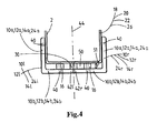
- FIG 4 a top view of a composite reinforcement member 10,12,14,14 is shown and its connections 40 to the bucket seat 2.
- the lateral parts 10b, 12b, 14, 24b extend at a distance 51 from the posterior side of the bucket seat 2.
- a gap 50 is provided between the lateral parts 10b, 12b, 14, 24b and the posterior surface of the bucket seat 2.
- the longitudinal reinforcement members 16 extend in the gap 50
- a spacer member 30 is provided centrally in order to support the ends 42L, 42R of the different reinforcement members.
- FIG. 5 a view of an L-shaped composite reinforcement member 10, 12, 14, 24 is shown.
- the composite reinforcement member can be pre-manufactured in one standard size or a few standard sizes.
- Holes 41 are provided in the L-form at suitable locations for connection with the bucket seat.
- a hole 41 a may be provided for connection with the flank of the bucket seat 2 and a hole 41 b may be provided for a connection with a bottom support section 4, back support section 5, shoulder support section 9, or head support section 6 of the bucket seat 2.
Landscapes
- Engineering & Computer Science (AREA)
- Aviation & Aerospace Engineering (AREA)
- Transportation (AREA)
- Mechanical Engineering (AREA)
- Seats For Vehicles (AREA)
Applications Claiming Priority (2)
| Application Number | Priority Date | Filing Date | Title |
|---|---|---|---|
| US14560909P | 2009-01-19 | 2009-01-19 | |
| NL2002430A NL2002430C2 (en) | 2009-01-19 | 2009-01-19 | Improved car seat. |
Publications (3)
| Publication Number | Publication Date |
|---|---|
| EP2208638A2 true EP2208638A2 (de) | 2010-07-21 |
| EP2208638A3 EP2208638A3 (de) | 2012-01-04 |
| EP2208638B1 EP2208638B1 (de) | 2014-10-29 |
Family
ID=41316820
Family Applications (1)
| Application Number | Title | Priority Date | Filing Date |
|---|---|---|---|
| EP10150996.6A Active EP2208638B1 (de) | 2009-01-19 | 2010-01-18 | Verbesserter Autositz |
Country Status (3)
| Country | Link |
|---|---|
| US (1) | US8342602B2 (de) |
| EP (1) | EP2208638B1 (de) |
| NL (1) | NL2002430C2 (de) |
Cited By (1)
| Publication number | Priority date | Publication date | Assignee | Title |
|---|---|---|---|---|
| FR3005613A1 (fr) * | 2013-05-15 | 2014-11-21 | Peugeot Citroen Automobiles Sa | Siege de vehicule |
Families Citing this family (7)
| Publication number | Priority date | Publication date | Assignee | Title |
|---|---|---|---|---|
| EP2697037B1 (de) * | 2011-04-15 | 2017-05-10 | Johnson Controls GmbH | Verstärktes strukturelement aus kunststoff insbesondere im fahrzeuginnenausstattungsbereich |
| MX343649B (es) | 2011-09-21 | 2016-11-14 | Miller Herman Inc | Reposacabezas de dos niveles, estructura de soporte del cuerpo y método para soportar el cráneo de un usuario. |
| CN102529765B (zh) * | 2011-12-04 | 2016-01-20 | 广西秀美壮乡能源环保有限公司 | 交通安全椅 |
| US10106068B2 (en) | 2017-01-05 | 2018-10-23 | Ford Global Technologies, Llc | Modular head restraint structure and styling enablement features |
| DE102018112643B3 (de) * | 2018-05-25 | 2019-08-29 | Dr. Ing. H.C. F. Porsche Aktiengesellschaft | Fahrzeugschalensitz, insbesondere für ein Motorsportfahrzeug |
| DE102019126456B4 (de) | 2019-10-01 | 2023-05-04 | Dr. Ing. H.C. F. Porsche Aktiengesellschaft | Kraftfahrzeugsitz und Kraftfahrzeug |
| CN113511124B (zh) * | 2021-05-28 | 2022-09-16 | 裴国成 | 一种带有侧防护和快速发热自调节功能的汽车座椅垫 |
Family Cites Families (14)
| Publication number | Priority date | Publication date | Assignee | Title |
|---|---|---|---|---|
| US254115A (en) * | 1882-02-28 | Vehicle-seat | ||
| FR799229A (fr) * | 1935-11-15 | 1936-06-09 | Bendix Aviat Corp | Siège de pilote réglable |
| US2393499A (en) * | 1943-09-02 | 1946-01-22 | Flrestone Tire & Rubber Compan | Seat for aircraft |
| DE2303289C3 (de) * | 1973-01-24 | 1979-12-13 | Recaro Gmbh & Co, 7000 Stuttgart | Schalensitz für Kraftfahrzeuge |
| DE3239292A1 (de) * | 1981-11-11 | 1983-05-19 | Keiper Automobiltechnik Gmbh & Co Kg, 5630 Remscheid | Rueckenlehnenrahmen fuer sitze, insbesondere fuer kraftfahrzeugsitze |
| DE3808316A1 (de) * | 1988-03-12 | 1989-09-21 | Keiper Recaro Gmbh Co | Rueckenlehne fuer einen fahrzeugsitz, insbesondere einen kraftfahrzeugsitz |
| DE8906062U1 (de) * | 1989-05-12 | 1989-07-06 | Lignotock Gmbh & Co, 7000 Stuttgart | Kraftfahrzeugsitz in Form eines muldenförmigen Trägerteils |
| US6491346B1 (en) * | 2000-06-01 | 2002-12-10 | Dow Global Technologies, Inc. | Seating system and method for making the same |
| US7128373B2 (en) * | 2002-09-27 | 2006-10-31 | Dow Global Technologies, Inc. | Seating system and method of forming same |
| US7111888B1 (en) * | 2003-09-09 | 2006-09-26 | Motorsports Builders, Llc | Molded safety seat |
| US7040708B2 (en) * | 2003-11-05 | 2006-05-09 | Racetech Manufacturing Ltd. | Vehicle seat |
| US20060138830A1 (en) * | 2004-12-23 | 2006-06-29 | Cho-Hsin Liu | Barrel shaped chair of a racing car |
| JP2006198128A (ja) * | 2005-01-20 | 2006-08-03 | Tachi S Co Ltd | アームレスト取付け可能なシート・バック・フレーム |
| US7959233B2 (en) * | 2008-12-19 | 2011-06-14 | Toyota Motor Engineering & Manufacturing North America, Inc. | Seat back assembly with integral reinforcement structure |
-
2009
- 2009-01-19 NL NL2002430A patent/NL2002430C2/en active
-
2010
- 2010-01-18 EP EP10150996.6A patent/EP2208638B1/de active Active
- 2010-01-19 US US12/689,573 patent/US8342602B2/en active Active
Non-Patent Citations (1)
| Title |
|---|
| None |
Cited By (1)
| Publication number | Priority date | Publication date | Assignee | Title |
|---|---|---|---|---|
| FR3005613A1 (fr) * | 2013-05-15 | 2014-11-21 | Peugeot Citroen Automobiles Sa | Siege de vehicule |
Also Published As
| Publication number | Publication date |
|---|---|
| NL2002430C2 (en) | 2010-07-20 |
| US8342602B2 (en) | 2013-01-01 |
| US20100181811A1 (en) | 2010-07-22 |
| EP2208638B1 (de) | 2014-10-29 |
| EP2208638A3 (de) | 2012-01-04 |
Similar Documents
| Publication | Publication Date | Title |
|---|---|---|
| EP2208638B1 (de) | Verbesserter Autositz | |
| US6817673B2 (en) | Vehicle seat assembly | |
| US7131697B2 (en) | Sports seat for a vehicle, especially for a motor vehicle | |
| DE102018112469B4 (de) | Grätschsitz-Fahrzeug | |
| JP6442349B2 (ja) | 乗物用シート | |
| DE112015001929B4 (de) | Befestigungsvorrichtung für ein Airbagmodul | |
| GB2515576A (en) | Vehicle Seat | |
| KR20080005361A (ko) | 차량시트 | |
| US7040708B2 (en) | Vehicle seat | |
| US20190225127A1 (en) | Seat for vehicles having an engagement edge | |
| US20110127823A1 (en) | Backrest for a rear seat of a motor vehicle | |
| CN107458280A (zh) | 具有联合调节选项的车辆座椅 | |
| DE102024109239A1 (de) | Lenkstangenverstärkung für ein dreirädriges fahrzeug | |
| JP6731816B2 (ja) | シートバックフレーム | |
| DE202021100036U1 (de) | Kindersitz für ein Fahrrad | |
| DE202011004794U1 (de) | Klappsattel, Vorrichtung zum Halten u. Stützen des Körpers eines Radfahrers in einer aerodynamisch günstigen Fahrhaltung | |
| JP6984223B2 (ja) | 鞍乗型車両のシート支持構造 | |
| JP4556210B2 (ja) | 車両用シート | |
| CN213008101U (zh) | 司机室脚蹬、司机室及车辆 | |
| CN107803427A (zh) | 一种底板零件拉伸折弯模具 | |
| CN211166582U (zh) | 一种商用车驾驶位座椅上靠背支架 | |
| DE102010023759A1 (de) | Fahrradsattel | |
| DE102011114742A1 (de) | Fahrzeugsitz, insbesondere Kraftfahrzeugsitz | |
| JP7194619B2 (ja) | 乗り物用シート | |
| JPH069946B2 (ja) | 自動車における子供用の安全座席 |
Legal Events
| Date | Code | Title | Description |
|---|---|---|---|
| PUAI | Public reference made under article 153(3) epc to a published international application that has entered the european phase |
Free format text: ORIGINAL CODE: 0009012 |
|
| AK | Designated contracting states |
Kind code of ref document: A2 Designated state(s): AT BE BG CH CY CZ DE DK EE ES FI FR GB GR HR HU IE IS IT LI LT LU LV MC MK MT NL NO PL PT RO SE SI SK SM TR |
|
| AX | Request for extension of the european patent |
Extension state: AL BA RS |
|
| PUAL | Search report despatched |
Free format text: ORIGINAL CODE: 0009013 |
|
| AK | Designated contracting states |
Kind code of ref document: A3 Designated state(s): AT BE BG CH CY CZ DE DK EE ES FI FR GB GR HR HU IE IS IT LI LT LU LV MC MK MT NL NO PL PT RO SE SI SK SM TR |
|
| AX | Request for extension of the european patent |
Extension state: AL BA RS |
|
| RIC1 | Information provided on ipc code assigned before grant |
Ipc: B60N 2/24 20060101ALI20111130BHEP Ipc: B60N 2/68 20060101AFI20111130BHEP |
|
| 17P | Request for examination filed |
Effective date: 20120702 |
|
| GRAP | Despatch of communication of intention to grant a patent |
Free format text: ORIGINAL CODE: EPIDOSNIGR1 |
|
| INTG | Intention to grant announced |
Effective date: 20140616 |
|
| GRAS | Grant fee paid |
Free format text: ORIGINAL CODE: EPIDOSNIGR3 |
|
| GRAA | (expected) grant |
Free format text: ORIGINAL CODE: 0009210 |
|
| AK | Designated contracting states |
Kind code of ref document: B1 Designated state(s): AT BE BG CH CY CZ DE DK EE ES FI FR GB GR HR HU IE IS IT LI LT LU LV MC MK MT NL NO PL PT RO SE SI SK SM TR |
|
| AX | Request for extension of the european patent |
Extension state: AL BA RS |
|
| REG | Reference to a national code |
Ref country code: GB Ref legal event code: FG4D |
|
| REG | Reference to a national code |
Ref country code: CH Ref legal event code: EP |
|
| REG | Reference to a national code |
Ref country code: AT Ref legal event code: REF Ref document number: 693402 Country of ref document: AT Kind code of ref document: T Effective date: 20141115 |
|
| REG | Reference to a national code |
Ref country code: IE Ref legal event code: FG4D |
|
| REG | Reference to a national code |
Ref country code: DE Ref legal event code: R096 Ref document number: 602010019781 Country of ref document: DE Effective date: 20141211 |
|
| REG | Reference to a national code |
Ref country code: NL Ref legal event code: T3 |
|
| REG | Reference to a national code |
Ref country code: AT Ref legal event code: MK05 Ref document number: 693402 Country of ref document: AT Kind code of ref document: T Effective date: 20141029 |
|
| REG | Reference to a national code |
Ref country code: LT Ref legal event code: MG4D |
|
| PG25 | Lapsed in a contracting state [announced via postgrant information from national office to epo] |
Ref country code: IS Free format text: LAPSE BECAUSE OF FAILURE TO SUBMIT A TRANSLATION OF THE DESCRIPTION OR TO PAY THE FEE WITHIN THE PRESCRIBED TIME-LIMIT Effective date: 20150228 Ref country code: NO Free format text: LAPSE BECAUSE OF FAILURE TO SUBMIT A TRANSLATION OF THE DESCRIPTION OR TO PAY THE FEE WITHIN THE PRESCRIBED TIME-LIMIT Effective date: 20150129 Ref country code: FI Free format text: LAPSE BECAUSE OF FAILURE TO SUBMIT A TRANSLATION OF THE DESCRIPTION OR TO PAY THE FEE WITHIN THE PRESCRIBED TIME-LIMIT Effective date: 20141029 Ref country code: LT Free format text: LAPSE BECAUSE OF FAILURE TO SUBMIT A TRANSLATION OF THE DESCRIPTION OR TO PAY THE FEE WITHIN THE PRESCRIBED TIME-LIMIT Effective date: 20141029 Ref country code: ES Free format text: LAPSE BECAUSE OF FAILURE TO SUBMIT A TRANSLATION OF THE DESCRIPTION OR TO PAY THE FEE WITHIN THE PRESCRIBED TIME-LIMIT Effective date: 20141029 Ref country code: PT Free format text: LAPSE BECAUSE OF FAILURE TO SUBMIT A TRANSLATION OF THE DESCRIPTION OR TO PAY THE FEE WITHIN THE PRESCRIBED TIME-LIMIT Effective date: 20150302 |
|
| PG25 | Lapsed in a contracting state [announced via postgrant information from national office to epo] |
Ref country code: PL Free format text: LAPSE BECAUSE OF FAILURE TO SUBMIT A TRANSLATION OF THE DESCRIPTION OR TO PAY THE FEE WITHIN THE PRESCRIBED TIME-LIMIT Effective date: 20141029 Ref country code: SE Free format text: LAPSE BECAUSE OF FAILURE TO SUBMIT A TRANSLATION OF THE DESCRIPTION OR TO PAY THE FEE WITHIN THE PRESCRIBED TIME-LIMIT Effective date: 20141029 Ref country code: LV Free format text: LAPSE BECAUSE OF FAILURE TO SUBMIT A TRANSLATION OF THE DESCRIPTION OR TO PAY THE FEE WITHIN THE PRESCRIBED TIME-LIMIT Effective date: 20141029 Ref country code: HR Free format text: LAPSE BECAUSE OF FAILURE TO SUBMIT A TRANSLATION OF THE DESCRIPTION OR TO PAY THE FEE WITHIN THE PRESCRIBED TIME-LIMIT Effective date: 20141029 Ref country code: CY Free format text: LAPSE BECAUSE OF FAILURE TO SUBMIT A TRANSLATION OF THE DESCRIPTION OR TO PAY THE FEE WITHIN THE PRESCRIBED TIME-LIMIT Effective date: 20141029 Ref country code: AT Free format text: LAPSE BECAUSE OF FAILURE TO SUBMIT A TRANSLATION OF THE DESCRIPTION OR TO PAY THE FEE WITHIN THE PRESCRIBED TIME-LIMIT Effective date: 20141029 Ref country code: GR Free format text: LAPSE BECAUSE OF FAILURE TO SUBMIT A TRANSLATION OF THE DESCRIPTION OR TO PAY THE FEE WITHIN THE PRESCRIBED TIME-LIMIT Effective date: 20150130 |
|
| REG | Reference to a national code |
Ref country code: DE Ref legal event code: R097 Ref document number: 602010019781 Country of ref document: DE |
|
| PG25 | Lapsed in a contracting state [announced via postgrant information from national office to epo] |
Ref country code: DK Free format text: LAPSE BECAUSE OF FAILURE TO SUBMIT A TRANSLATION OF THE DESCRIPTION OR TO PAY THE FEE WITHIN THE PRESCRIBED TIME-LIMIT Effective date: 20141029 Ref country code: RO Free format text: LAPSE BECAUSE OF FAILURE TO SUBMIT A TRANSLATION OF THE DESCRIPTION OR TO PAY THE FEE WITHIN THE PRESCRIBED TIME-LIMIT Effective date: 20141029 Ref country code: CZ Free format text: LAPSE BECAUSE OF FAILURE TO SUBMIT A TRANSLATION OF THE DESCRIPTION OR TO PAY THE FEE WITHIN THE PRESCRIBED TIME-LIMIT Effective date: 20141029 Ref country code: EE Free format text: LAPSE BECAUSE OF FAILURE TO SUBMIT A TRANSLATION OF THE DESCRIPTION OR TO PAY THE FEE WITHIN THE PRESCRIBED TIME-LIMIT Effective date: 20141029 Ref country code: SK Free format text: LAPSE BECAUSE OF FAILURE TO SUBMIT A TRANSLATION OF THE DESCRIPTION OR TO PAY THE FEE WITHIN THE PRESCRIBED TIME-LIMIT Effective date: 20141029 |
|
| REG | Reference to a national code |
Ref country code: CH Ref legal event code: PL |
|
| PG25 | Lapsed in a contracting state [announced via postgrant information from national office to epo] |
Ref country code: LU Free format text: LAPSE BECAUSE OF FAILURE TO SUBMIT A TRANSLATION OF THE DESCRIPTION OR TO PAY THE FEE WITHIN THE PRESCRIBED TIME-LIMIT Effective date: 20150118 |
|
| PLBE | No opposition filed within time limit |
Free format text: ORIGINAL CODE: 0009261 |
|
| STAA | Information on the status of an ep patent application or granted ep patent |
Free format text: STATUS: NO OPPOSITION FILED WITHIN TIME LIMIT |
|
| PG25 | Lapsed in a contracting state [announced via postgrant information from national office to epo] |
Ref country code: MC Free format text: LAPSE BECAUSE OF FAILURE TO SUBMIT A TRANSLATION OF THE DESCRIPTION OR TO PAY THE FEE WITHIN THE PRESCRIBED TIME-LIMIT Effective date: 20141029 |
|
| 26N | No opposition filed |
Effective date: 20150730 |
|
| PG25 | Lapsed in a contracting state [announced via postgrant information from national office to epo] |
Ref country code: LI Free format text: LAPSE BECAUSE OF NON-PAYMENT OF DUE FEES Effective date: 20150131 Ref country code: CH Free format text: LAPSE BECAUSE OF NON-PAYMENT OF DUE FEES Effective date: 20150131 |
|
| REG | Reference to a national code |
Ref country code: IE Ref legal event code: MM4A |
|
| PG25 | Lapsed in a contracting state [announced via postgrant information from national office to epo] |
Ref country code: IE Free format text: LAPSE BECAUSE OF NON-PAYMENT OF DUE FEES Effective date: 20150118 |
|
| PG25 | Lapsed in a contracting state [announced via postgrant information from national office to epo] |
Ref country code: SI Free format text: LAPSE BECAUSE OF FAILURE TO SUBMIT A TRANSLATION OF THE DESCRIPTION OR TO PAY THE FEE WITHIN THE PRESCRIBED TIME-LIMIT Effective date: 20141029 |
|
| REG | Reference to a national code |
Ref country code: FR Ref legal event code: PLFP Year of fee payment: 7 |
|
| PG25 | Lapsed in a contracting state [announced via postgrant information from national office to epo] |
Ref country code: MT Free format text: LAPSE BECAUSE OF FAILURE TO SUBMIT A TRANSLATION OF THE DESCRIPTION OR TO PAY THE FEE WITHIN THE PRESCRIBED TIME-LIMIT Effective date: 20141029 |
|
| REG | Reference to a national code |
Ref country code: FR Ref legal event code: PLFP Year of fee payment: 8 |
|
| PG25 | Lapsed in a contracting state [announced via postgrant information from national office to epo] |
Ref country code: SM Free format text: LAPSE BECAUSE OF FAILURE TO SUBMIT A TRANSLATION OF THE DESCRIPTION OR TO PAY THE FEE WITHIN THE PRESCRIBED TIME-LIMIT Effective date: 20141029 Ref country code: HU Free format text: LAPSE BECAUSE OF FAILURE TO SUBMIT A TRANSLATION OF THE DESCRIPTION OR TO PAY THE FEE WITHIN THE PRESCRIBED TIME-LIMIT; INVALID AB INITIO Effective date: 20100118 Ref country code: BG Free format text: LAPSE BECAUSE OF FAILURE TO SUBMIT A TRANSLATION OF THE DESCRIPTION OR TO PAY THE FEE WITHIN THE PRESCRIBED TIME-LIMIT Effective date: 20141029 |
|
| PG25 | Lapsed in a contracting state [announced via postgrant information from national office to epo] |
Ref country code: TR Free format text: LAPSE BECAUSE OF FAILURE TO SUBMIT A TRANSLATION OF THE DESCRIPTION OR TO PAY THE FEE WITHIN THE PRESCRIBED TIME-LIMIT Effective date: 20141029 |
|
| PG25 | Lapsed in a contracting state [announced via postgrant information from national office to epo] |
Ref country code: BE Free format text: LAPSE BECAUSE OF FAILURE TO SUBMIT A TRANSLATION OF THE DESCRIPTION OR TO PAY THE FEE WITHIN THE PRESCRIBED TIME-LIMIT Effective date: 20141029 |
|
| REG | Reference to a national code |
Ref country code: FR Ref legal event code: PLFP Year of fee payment: 9 |
|
| PG25 | Lapsed in a contracting state [announced via postgrant information from national office to epo] |
Ref country code: MK Free format text: LAPSE BECAUSE OF FAILURE TO SUBMIT A TRANSLATION OF THE DESCRIPTION OR TO PAY THE FEE WITHIN THE PRESCRIBED TIME-LIMIT Effective date: 20141029 |
|
| P01 | Opt-out of the competence of the unified patent court (upc) registered |
Effective date: 20230508 |
|
| PGFP | Annual fee paid to national office [announced via postgrant information from national office to epo] |
Ref country code: NL Payment date: 20260126 Year of fee payment: 17 |
|
| PGFP | Annual fee paid to national office [announced via postgrant information from national office to epo] |
Ref country code: GB Payment date: 20260122 Year of fee payment: 17 |
|
| PGFP | Annual fee paid to national office [announced via postgrant information from national office to epo] |
Ref country code: DE Payment date: 20260120 Year of fee payment: 17 |
|
| PGFP | Annual fee paid to national office [announced via postgrant information from national office to epo] |
Ref country code: IT Payment date: 20260130 Year of fee payment: 17 |
|
| PGFP | Annual fee paid to national office [announced via postgrant information from national office to epo] |
Ref country code: FR Payment date: 20260121 Year of fee payment: 17 |