EP2203101B1 - Fahrbarer staubsauger sowie lenkrolle eines fahrbaren staubsaugers - Google Patents
Fahrbarer staubsauger sowie lenkrolle eines fahrbaren staubsaugers Download PDFInfo
- Publication number
- EP2203101B1 EP2203101B1 EP08803515.9A EP08803515A EP2203101B1 EP 2203101 B1 EP2203101 B1 EP 2203101B1 EP 08803515 A EP08803515 A EP 08803515A EP 2203101 B1 EP2203101 B1 EP 2203101B1
- Authority
- EP
- European Patent Office
- Prior art keywords
- vacuum cleaner
- housing
- caster
- caster housing
- roller
- Prior art date
- Legal status (The legal status is an assumption and is not a legal conclusion. Google has not performed a legal analysis and makes no representation as to the accuracy of the status listed.)
- Not-in-force
Links
Images


Classifications
-
- A—HUMAN NECESSITIES
- A47—FURNITURE; DOMESTIC ARTICLES OR APPLIANCES; COFFEE MILLS; SPICE MILLS; SUCTION CLEANERS IN GENERAL
- A47L—DOMESTIC WASHING OR CLEANING; SUCTION CLEANERS IN GENERAL
- A47L9/00—Details or accessories of suction cleaners, e.g. mechanical means for controlling the suction or for effecting pulsating action; Storing devices specially adapted to suction cleaners or parts thereof; Carrying-vehicles specially adapted for suction cleaners
- A47L9/009—Carrying-vehicles; Arrangements of trollies or wheels; Means for avoiding mechanical obstacles
-
- B—PERFORMING OPERATIONS; TRANSPORTING
- B60—VEHICLES IN GENERAL
- B60B—VEHICLE WHEELS; CASTORS; AXLES FOR WHEELS OR CASTORS; INCREASING WHEEL ADHESION
- B60B33/00—Castors in general ; Anti-clogging castors
- B60B33/0002—Castors in general ; Anti-clogging castors assembling to the object, e.g. furniture
-
- B—PERFORMING OPERATIONS; TRANSPORTING
- B60—VEHICLES IN GENERAL
- B60B—VEHICLE WHEELS; CASTORS; AXLES FOR WHEELS OR CASTORS; INCREASING WHEEL ADHESION
- B60B33/00—Castors in general ; Anti-clogging castors
- B60B33/0002—Castors in general ; Anti-clogging castors assembling to the object, e.g. furniture
- B60B33/0005—Castors in general ; Anti-clogging castors assembling to the object, e.g. furniture characterised by mounting method
-
- B—PERFORMING OPERATIONS; TRANSPORTING
- B60—VEHICLES IN GENERAL
- B60B—VEHICLE WHEELS; CASTORS; AXLES FOR WHEELS OR CASTORS; INCREASING WHEEL ADHESION
- B60B33/00—Castors in general ; Anti-clogging castors
- B60B33/0002—Castors in general ; Anti-clogging castors assembling to the object, e.g. furniture
- B60B33/0015—Castors in general ; Anti-clogging castors assembling to the object, e.g. furniture characterised by adaptations made to castor
- B60B33/0021—Castors in general ; Anti-clogging castors assembling to the object, e.g. furniture characterised by adaptations made to castor in the form of a mounting pin
-
- B—PERFORMING OPERATIONS; TRANSPORTING
- B60—VEHICLES IN GENERAL
- B60B—VEHICLE WHEELS; CASTORS; AXLES FOR WHEELS OR CASTORS; INCREASING WHEEL ADHESION
- B60B33/00—Castors in general ; Anti-clogging castors
- B60B33/0002—Castors in general ; Anti-clogging castors assembling to the object, e.g. furniture
- B60B33/0015—Castors in general ; Anti-clogging castors assembling to the object, e.g. furniture characterised by adaptations made to castor
- B60B33/0023—Castors in general ; Anti-clogging castors assembling to the object, e.g. furniture characterised by adaptations made to castor in the form of specific adaptations to the form of the object
-
- B—PERFORMING OPERATIONS; TRANSPORTING
- B60—VEHICLES IN GENERAL
- B60B—VEHICLE WHEELS; CASTORS; AXLES FOR WHEELS OR CASTORS; INCREASING WHEEL ADHESION
- B60B33/00—Castors in general ; Anti-clogging castors
- B60B33/0002—Castors in general ; Anti-clogging castors assembling to the object, e.g. furniture
- B60B33/0026—Castors in general ; Anti-clogging castors assembling to the object, e.g. furniture characterised by adaptations made to the object
-
- B—PERFORMING OPERATIONS; TRANSPORTING
- B60—VEHICLES IN GENERAL
- B60B—VEHICLE WHEELS; CASTORS; AXLES FOR WHEELS OR CASTORS; INCREASING WHEEL ADHESION
- B60B33/00—Castors in general ; Anti-clogging castors
- B60B33/0036—Castors in general ; Anti-clogging castors characterised by type of wheels
- B60B33/0039—Single wheels
-
- B—PERFORMING OPERATIONS; TRANSPORTING
- B60—VEHICLES IN GENERAL
- B60B—VEHICLE WHEELS; CASTORS; AXLES FOR WHEELS OR CASTORS; INCREASING WHEEL ADHESION
- B60B33/00—Castors in general ; Anti-clogging castors
- B60B33/0047—Castors in general ; Anti-clogging castors characterised by details of the rolling axle
- B60B33/0049—Castors in general ; Anti-clogging castors characterised by details of the rolling axle the rolling axle being horizontal
-
- B—PERFORMING OPERATIONS; TRANSPORTING
- B60—VEHICLES IN GENERAL
- B60B—VEHICLE WHEELS; CASTORS; AXLES FOR WHEELS OR CASTORS; INCREASING WHEEL ADHESION
- B60B33/00—Castors in general ; Anti-clogging castors
- B60B33/0047—Castors in general ; Anti-clogging castors characterised by details of the rolling axle
- B60B33/0057—Castors in general ; Anti-clogging castors characterised by details of the rolling axle the rolling axle being offset from swivel axis
-
- B—PERFORMING OPERATIONS; TRANSPORTING
- B60—VEHICLES IN GENERAL
- B60B—VEHICLE WHEELS; CASTORS; AXLES FOR WHEELS OR CASTORS; INCREASING WHEEL ADHESION
- B60B33/00—Castors in general ; Anti-clogging castors
- B60B33/006—Castors in general ; Anti-clogging castors characterised by details of the swivel mechanism
- B60B33/0065—Castors in general ; Anti-clogging castors characterised by details of the swivel mechanism characterised by details of the swivel axis
- B60B33/0068—Castors in general ; Anti-clogging castors characterised by details of the swivel mechanism characterised by details of the swivel axis the swivel axis being vertical
-
- B—PERFORMING OPERATIONS; TRANSPORTING
- B60—VEHICLES IN GENERAL
- B60B—VEHICLE WHEELS; CASTORS; AXLES FOR WHEELS OR CASTORS; INCREASING WHEEL ADHESION
- B60B33/00—Castors in general ; Anti-clogging castors
- B60B33/006—Castors in general ; Anti-clogging castors characterised by details of the swivel mechanism
- B60B33/0065—Castors in general ; Anti-clogging castors characterised by details of the swivel mechanism characterised by details of the swivel axis
- B60B33/0073—Castors in general ; Anti-clogging castors characterised by details of the swivel mechanism characterised by details of the swivel axis the swivel axis being symmetrical to wheel or wheels
Definitions
- the invention relates to a mobile vacuum cleaner and a steering roller of a mobile vacuum cleaner according to the preambles of the independent claims.
- Upright vacuum cleaner essentially consist of a base body for receiving in particular mechanical and electrical components and a suction hose connected to the housing, to which a telescopic tube or a suction nozzle can be coupled.
- the user When operating the vacuum cleaner, the user generally holds the telescopic tube by an associated handle, which allows him to guide the suction nozzle over the surface to be cleaned.
- Mobile vacuum cleaners are usually operated by pulling on the suction hose, with the operator dragging the device mounted on at least one swivel castor behind him.
- two steering rollers are provided, which are arranged in the rear region of the vacuum cleaner. However, it can also be provided with additional castors in the front area.
- the steering rollers usually comprise a spherical or cambered castor housing and a roller which is mounted for rotation about a substantially horizontal axis on the castor housing.
- the castor housing is usually mounted with the aid of a bearing pin about a substantially vertical axis pivotally or rotatably mounted on the vacuum cleaner.
- the castors are indeed capable of steering.
- this steering ability is particularly limited when obstacles such as door sills and the like are to be overcome.
- most of a plastic such as a polypropylene (PP) manufactured rollers that are mounted on a plastic or metal pin produce disturbing running noise.
- the roller itself is usually made of thermoplastic elastomers (TPE).
- the roller is usually mounted on a molded plastic axis or a separate metal pin that serves as a bearing point, axially movable in the housing of the castor. In this case, the roller with its flanks touch the recess in the steering roller, resulting in an adverse noise.
- From the DE 28 24 033 A1 is a vacuum cleaner with a fixed skid at the bottom and a pivotally mounted within this about a vertical axis mounted separate roller, wherein the skid is combined with the roller to a structural unit, wherein the roller in the skid and the skid pivotally about the vertical Axis is stored.
- the skid is designed as a carrier element for the roller circular and provided with a molded ramp, which almost tangent to the tread of the roller.
- a pivotable roller with a vertical pivot axis known, which is mounted in a serving as a swivel arm bearing housing for the roller with proper distance from the roller axis of rotation.
- the bearing housing is designed as the roller up to approximately in rotational axis height enclosing plastic housing.
- the pivot axis is mounted in a reinforced region of a housing cover wall by means of a double-row radial ball bearing whose outer ring is formed by the reinforced area of the housing cover wall.
- the object of the invention is to provide a generic vacuum cleaner and castors a mobile vacuum cleaner, which allow a high maneuverability at the lowest possible noise.
- the castor housing has a substantially circular cross-section, wherein the roller is arranged close to the circumference.
- the castor housing is in a preferred embodiment, wedge-shaped over the base in the roller region of the base body and forms with its protruding from the base body area an inclined plane which is inclined by about 20 to 30 ° against the base of the base body in the region of the steering roller housing.
- the inclination is 25 °.
- the castor housing is formed spherical or cambered, wherein the castor is mounted off-center on a peripheral portion of the castor housing, which is axially increased.
- a separate bush is used axially in the castor housing for transmitting forces in the spatial axes.
- the connection between the bush and castor housing is designed so that forces in the spatial axes can be transmitted, for example via clamping, gluing or caulking.
- the socket is thus non-positively connected to the castor housing.
- the socket is made according to the invention of plastic and preferably pressed or caulked in the castor housing.
- the steering roller housing according to the invention is made of a metal, more preferably of a die-cast zinc, which brings an advantageous increase in mass with it.
- the bushing is connected along a vertical axis via a bearing journal with the base body of the vacuum cleaner, wherein a pair of materials of the bushing to the bearing pin is designed so that a friction can be reduced.
- a very light and quiet rotation of the steering roller is advantageously achieved.
- manufacturing tolerances are reduced.
- the roller is arranged with spacer elements in a recess of the steering roller housing, wherein the spacer elements are preferably arranged axially respectively on the outside of the roller.
- the spacer elements are designed as shims made of plastic, which prevent the roller touches the castor housing.
- the spacer elements may also be formed as a plate spring, so that the roller is always arranged approximately symmetrically in the recess of the steering roller housing, which has favorable effects on the running behavior. The rotation around the guide pin is improved by the narrowed tolerances, whereby the turning noise is minimized, so that it is barely audible.
- the device In conjunction with the mass increase on the castor wheel, this conveniently turns much longer than in a plastic version. At the same time, the device is given a higher-quality version.
- the follow-up behavior of vacuum cleaners is thus significantly improved, so that the device better follows the customer through the rooms and also rolls on obstacles such as furniture edges or chair legs better.
- the proposed solution is characterized by a high maneuverability with a simultaneously favorable driving stability.
- Fig. 1 a shows a side view of a preferred embodiment of a steering roller 12 of a mobile vacuum cleaner, not shown
- Fig. 2b shows the steering roller 12 in a sectional view.
- the steering roller 12 comprises a castor housing 13 and a roller 14 which is arranged eccentrically on a peripheral portion 20 of the castor housing 13.
- the roller 14 is rotatably mounted on the castor housing 13 about a substantially horizontal axis 15.
- the castor housing 13 is pivotable about a substantially vertical axis 16 and rotatably mounted on a base body 10, not shown, of the vacuum cleaner.
- the castor housing 13 has at that circumferential portion 20 on which the roller 14 is arranged, the largest axial Height 17 on. In cross section, the castor housing 13 is thus wedge-shaped, wherein the roller 14 is mounted in the region of the wedge tip.
- Fig. 2a is a perspective detailed view of the steering roller housing 13 is shown.
- the castor housing 13 has a substantially circular cross section, wherein the roller 14 is arranged circumferentially close to a circumference of the castor housing 13. Axially in the castor housing 13, a separate sleeve 22 for transmitting forces in the spatial axes is arranged.
- the sleeve 22 is non-positively connected to the castor housing 13.
- the sleeve 22 is made of plastic and preferably caulked or clamped in the castor housing 13.
- the castor housing 13 is preferably made of a die-cast zinc and has radially extending reinforcing ribs 24 on one of the two end faces. By the reinforcing ribs 24, the castor housing 13 receives on its wall a higher stability.
- roller 14 is provided in a peripheral portion 20 of the castor housing 13 in a peripheral portion 20 of the castor housing 13 in a recess 21 for in Fig. 2b shown roller 14 is provided.
- the roller 14 is mounted on a bolt arranged along the horizontal axis 15 and radially aligned within the steering wheel housing 13.
- the roller 14 is made of an abrasion-resistant plastic and has on its tread a convex contour to support the elasticity of the roller 14.
- a bearing pin 23 inserted ( Fig. 2b ).
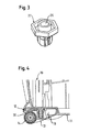
- Fig. 3 shows a detailed view of a preferred embodiment of a sleeve 22 made of plastic with a hexagonal outer contour.
- the sleeve 22 has axially a receptacle 25 for the bearing pin 23, not shown.
- Fig. 4 is a sectional view of a base body 10 of a mobile vacuum cleaner with a preferred steering roller 12, wherein the steering roller 12 at the rear of the Vacuum cleaner is provided.
- the steering roller 12 projects with its castor housing 13 in a wedge shape over the base 11 in the roller region of the base body 10.
- the castor housing 13 forms with its near-bottom region an inclined plane, which is inclined at an angle 18 of preferably 25 ° to the base 11 of the base body 10.
- the castor housing 13 In the peripheral portion 20, on which the roller 14 is arranged, the castor housing 13 has the largest axial height 17 (see FIG. Fig. 1a ) on.
- the axial height 17 is designed so that it corresponds to a diameter of the roller 14 in order to allow unhindered running of the roller 14.
- the castor housing 13 In the portion opposite the peripheral portion 20, the castor housing 13 is aligned with the base 11 of the base body 10th
Landscapes
- Engineering & Computer Science (AREA)
- Mechanical Engineering (AREA)
- Electric Suction Cleaners (AREA)
Description
- Die Erfindung betrifft einen fahrbaren Staubsauger sowie eine Lenkrolle eines fahrbaren Staubsaugers nach den Oberbegriffen der unabhängigen Ansprüche.
- Bodenstaubsauger bestehen im Wesentlichen aus einem Basiskörper zur Aufnahme von insbesondere mechanischen und elektrischen Komponenten und einem an das Gehäuse angeschlossenen Saugschlauch, an den ein Teleskoprohr bzw. eine Saugdüse ankoppelbar ist. Beim Betrieb des Staubsaugers hält der Anwender das Teleskoprohr im Allgemeinen an einem zugehörigen Handgriff, wodurch er die Saugdüse über die zu reinigende Oberfläche führen kann. Fahrbare Staubsauger werden üblicherweise durch Ziehen am Saugschlauch bedient, wobei der Bediener das auf wenigstens einer Lenkrolle gelagerte Gerät hinter sich herzieht. Üblicherweise sind zwei Lenkrollen vorgesehen, die im Heckbereich des Staubsaugers angeordnet sind. Es können jedoch auch zusätzliche Lenkrollen im Frontbereich vorgesehen ein.
- Die Lenkrollen umfassen üblicherweise ein kugeliges oder bombiertes Lenkrollengehäuse und eine Laufrolle, die um eine im Wesentlichen horizontale Achse drehbar an dem Lenkrollengehäuse gelagert ist. Das Lenkrollengehäuse ist meist mit Hilfe eines Lagerzapfens um eine im Wesentlichen vertikale Achse schwenkbar bzw. drehbar am Staubsauger gelagert. Dadurch sind die Lenkrollen zwar lenkfähig. Diese Lenkfähigkeit ist jedoch insbesondere dann eingeschränkt, wenn Hindernisse wie z.B. Türschwellen und dgl. überwunden werden sollen. Außerdem produzieren die meist aus einem Kunststoff wie beispielsweise einem Polypropxylen (PP) gefertigten Laufrollen, die an einem Kunststoff- oder Metallzapfen gelagert sind, störende Laufgeräusche. Die Laufrolle selbst ist meist aus thermoplastischen Elastomeren (TPE) gefertigt. Die Laufrolle wird meist über eine angespritzte Kunststoffachse oder über einen separaten Metallstift, der als Lagerstelle dient, in dem Gehäuse der Lenkrolle axial beweglich gelagert. Dabei kann die Laufrolle mit ihren Flanken die Aussparung in der Lenkrolle berühren, was zu einer nachteiligen Geräuschentwicklung führt.
- Aus der
DE 28 24 033 A1 ist ein Staubsauger mit einer festen Gleitkufe an der Unterseite und einer innerhalb dieser um eine vertikale Achse schwenkbar gelagerten separaten Laufrolle bekannt, bei dem die Gleitkufe mit der Laufrolle zu einer Baueinheit zusammengefasst ist, wobei die Laufrolle in der Gleitkufe und die Gleitkufe schwenkbar um die vertikale Achse gelagert ist. Die Gleitkufe ist dabei als Trägerelement für die Laufrolle kreisrund ausgebildet und mit einer angeformten Auflaufschräge versehen, die annähernd mit der Lauffläche der Laufrolle tangiert. - Ähnliche Anordnungen sind auch aus den Druckschriften
US 4,852,208 undJP 03251220 A - Aus der
DE 2 153 324 A1 ist eine schwenkbare Laufrolle mit einer senkrechten Schwenkachse bekannt, die in einem als Schwenkarm dienenden Lagergehäuse für die Laufrolle mit waggerechtem Abstand von der Rollendrehachse gelagert ist. Das Lagergehäuse ist dabei als die Laufrolle bis etwa in Drehachsenhöhe umschließendes Kunststoffgehäuse ausgebildet. Die Schwenkachse ist in einem verstärkten Bereich einer Gehäusedeckwand mittels eines zweireihigen Radialkugellagers gelagert, dessen Außenring von dem verstärkten Bereich der Gehäusedeckwand gebildet ist. - Aufgabe der Erfindung ist es, einen gattungsgemäßen Staubsauger sowie Lenkrollen eines fahrbaren Staubsaugers bereitzustellen, die eine hohe Manövrierfähigkeit bei einem möglichst geringen Laufgeräusch ermöglichen.
- Diese Aufgabe wird erfindungsgemäß mit den Merkmalen der unabhängigen Ansprüche gelöst.
- Ein erfindungsgemäßer fahrbarer Staubsauger geht aus von einem Basiskörper, an dessen Unterseite mit einer Grundfläche mindestens eine Lenkrolle in einem Rollenbereich angeordnet ist, wobei die Lenkrolle eine in einem Lenkrollengehäuse außermittig an einem Umfangsabschnitt angeordnete Laufrolle umfasst, die um eine im Wesentlichen horizontale Achse drehbar an dem Lenkrollengehäuse gelagert ist, und wobei das Lenkrollengehäuse um eine im Wesentlichen vertikale Achse schwenkbar bzw. drehbar am Staubsauger gelagert ist und an jenem Umfangsabschnitt, an dem die Laufrolle angeordnet ist, die größte axiale Höhe aufweist. Es wird vorgeschlagen, dass das Lenkrollengehäuse aus einem Metall gefertigt ist und dass axial in dem Lenkrollengehäuse eine separate Buchse zur Übertragung von Kräften in den Raumachsen angeordnet ist, welche aus einem Kunststoff gefertigt ist. Eine erfindungsgemäße Lenkrolle eines fahrbaren Staubsaugers umfasst ein solches Lenkrollengehäuse mit einer separaten Buchse und einer Laufrolle.
- Durch die außermittige Anordnung der Laufrolle wird eine definierte Schwenkbewegung der Lenkrolle beim Bewegen des Staubsaugers ermöglicht. Vorteilhafterweise entsteht mit der vorgeschlagenen geometrischen Gestaltung ein definierter Drehpunkt am Lenkrollengehäuse, was das Überfahren von Hindernissen wie beispielsweise von Türschwellen oder Zuleitungskabeln erheblich erleichtert.
- Bevorzugt weist das Lenkrollengehäuse einen im Wesentlichen kreisförmigen Querschnitt auf, wobei die Laufrolle umfangsnah angeordnet ist. Das Lenkrollengehäuse steht bei einer bevorzugten Ausführungsform keilförmig über die Grundfläche im Rollenbereich des Basiskörpers über und bildet mit seinem aus dem Basiskörper herausragenden Bereich eine schiefe Ebene, die um etwa 20 bis 30° gegen die Grundfläche des Basiskörpers im Bereich des Lenkrollengehäuses geneigt ist. In einer besonders bevorzugten Ausführungsform beträgt die Neigung 25°. Beim Überfahren von Hindernissen gleitet das Hindernis zunächst sanft entlang der schiefen Ebene von dem grundflächennahen Bereich des Lenkrollengehäuses bis zur Keilspitze, wo das Laufrad angeordnet ist. Eine harte Kollision mit Hindernissen wird dabei verhindert, was den Verschleiß der Lenkrolle günstigerweise erheblich reduziert. Hinzu kommt, dass bei der vorgeschlagenen Anordnung des Laufrades eine besonders günstige Bodenfreiheit erzielt wird.
- In einer einfacheren Ausführungsform wäre auch denkbar, dass das Lenkrollengehäuse kugelig bzw. bombiert ausgebildet ist, wobei die Lenkrolle außermittig an einem Umfangsabschnitt des Lenkrollengehäuses gelagert ist, der axial erhöht ist.
- Erfindungsgemäß ist axial in dem Lenkrollengehäuse eine separate Buchse zur Übertragung von Kräften in den Raumachsen eingesetzt. Günstigerweise ist die Verbindung zwischen Buchse und Lenkrollengehäuse so gestaltet, dass Kräfte in den Raumachsen übertragen werden können, beispielsweise über Klemmung, Klebung oder Verstemmung. Günstigerweise ist die Buchse somit kraftschlüssig mit dem Lenkrollengehäuse verbunden. Die Buchse ist erfindungsgemäß aus Kunststoff gefertigt und in das Lenkrollengehäuse bevorzugt eingepresst oder verstemmt. Das Lenkrollengehäuse ist erfindungsgemäß aus einem Metall gefertigt, besonders bevorzugt aus einem Zinkdruckguss, was eine vorteilhafte Masseerhöhung mit sich bringt.
- Die Buchse ist entlang einer vertikalen Achse über einen Lagerzapfen mit dem Basiskörper des Staubsaugers verbunden, wobei eine Materialpaarung der Buchse zu dem Lagerzapfen so ausgelegt ist, dass eine Reibung reduzierbar ist. Dadurch wird vorteilhafterweise eine sehr leichte und geräuscharme Drehung von der Lenkrolle erreicht. Hinzu kommt, dass fertigungstechnische Toleranzen reduziert werden.
- Bevorzugt ist die Laufrolle mit Abstandselementen in einer Aussparung des Lenkrollengehäuses angeordnet, wobei die Abstandselemente bevorzugt axial jeweils auf der Außenseite der Laufrolle angeordnet sind. Günstigerweise sind die Abstandselemente als Beilagenscheiben aus Kunststoff ausgebildet, die verhindern, dass die Laufrolle das Lenkrollengehäuse berührt. In einer günstigen Variante können die Abstandselemente auch als Tellerfeder ausgebildet sein, so dass die Laufrolle immer annähernd symmetrisch in der Aussparung des Lenkrollengehäuses angeordnet ist, was günstige Auswirkungen auf das Laufverhalten hat. Die Rotation um den Führungszapfen wird durch die eingeengten Toleranzen verbessert, wodurch das Drehgeräusch minimiert wird, so dass es kaum noch hörbar ist.
- In Verbindung mit der Masseerhöhung an der Lenkrolle dreht sich diese günstigerweise wesentlich länger als bei einer Ausführung aus Kunststoff. Gleichzeitig wird dem Gerät eine höherwertige Ausführung verliehen. Das Nachlaufverhalten von Bodenstaubsaugern wird damit erheblich verbessert, wodurch das Gerät dem Kunden besser durch die Räume folgt und auch an Hindernissen wie beispielsweise Möbelkanten oder Stuhlbeinen besser abrollt. Die vorgeschlagene Lösung zeichnet sich durch eine hohe Manövrierfähigkeit bei einer gleichzeitig günstigen Fahrstabilität aus.
- Anhand eines in der Zeichnung dargestellten Ausführungsbeispiels wird die Erfindung nachfolgend näher beschrieben. Es zeigt:
- Fig. 1a,1b
- eine bevorzugten Ausführungsform einer Lenkrolle eines fahrbaren Staubsaugers in einer Seitenansicht (
Fig. 1 a) sowie in einer Schnittdarstellung (Fig. 1 b) ; - Fig. 2a, 2b
- eine perspektivische Detailansicht eines bevorzugten Lenkrollengehäuses (
Fig. 2a ) sowie eine perspektivische Darstellung des Lenkrollengehäuses mit montierter Laufrolle sowie mit einem Lagerzapfen (Fig. 2b ); - Fig. 3
- eine perspektivische Ansicht einer bevorzugten Buchse eines Lenkrollengehäuses; und
- Fig. 4
- eine Schnittdarstellung eines Basiskörpers eines fahrbaren Staubsaugers mit montierter Lenkrolle.
- In den Figuren werden gleiche oder im Wesentlichen gleich bleibende Elemente mit den gleichen Bezugszeichen versehen.
-
Fig. 1 a zeigt eine Seitenansicht einer bevorzugten Ausführungsform einer Lenkrolle 12 eines nicht gezeigten fahrbaren Staubsaugers,Fig. 2b zeigt die Lenkrolle 12 in einer Schnittdarstellung. Die Lenkrolle 12 umfasst ein Lenkrollengehäuse 13 sowie eine Laufrolle 14, die außermittig an einem Umfangsabschnitt 20 des Lenkrollengehäuses 13 angeordnet ist. Die Laufrolle 14 ist um eine im Wesentlichen horizontale Achse 15 drehbar an dem Lenkrollengehäuse 13 gelagert. Das Lenkrollengehäuse 13 ist um eine im Wesentlichen vertikale Achse 16 schwenkbar bzw. drehbar an einem nicht dargestellten Basiskörper 10 des Staubsaugers gelagert. Das Lenkrollengehäuse 13 weist an jenem Umfangsabschnitt 20, an dem die Laufrolle 14 angeordnet ist, die größte axiale Höhe 17 auf. Im Querschnitt ist das Lenkrollengehäuse 13 somit keilförmig ausgebildet, wobei die Laufrolle 14 im Bereich der Keilspitze gelagert ist. - In
Fig. 2a ist eine perspektivische Detailansicht des Lenkrollengehäuses 13 dargestellt. Das Lenkrollengehäuse 13 weist einen im Wesentlichen kreisförmigen Querschnitt auf, wobei umfangsnah an einem Umfang des Lenkrollengehäuses 13 die Laufrolle 14 angeordnet ist. Axial in dem Lenkrollengehäuse 13 ist eine separate Buchse 22 zur Übertragung von Kräften in den Raumachsen angeordnet. Die Buchse 22 ist kraftschlüssig mit dem Lenkrollengehäuse 13 verbunden. Die Buchse 22 ist aus Kunststoff gefertigt und vorzugsweise in das Lenkrollengehäuse 13 verstemmt oder geklemmt. Das Lenkrollengehäuse 13 ist bevorzugt aus einem Zinkdruckguss gefertigt und weist auf einer der beiden Stirnseiten radial verlaufende Verstärkungsrippen 24 auf. Durch die Verstärkungsrippen 24 erhält das Lenkrollengehäuse 13 an seiner Wand eine höhere Stabilität auf. - In einem Umfangsabschnitt 20 des Lenkrollengehäuses 13 ist eine Aussparung 21 für die in
Fig. 2b dargestellte Laufrolle 14 vorgesehen. Die Laufrolle 14 ist auf einem entlang der horizontalen Achse 15 angeordneten Bolzen gelagert und innerhalb des Lenkradgehäuses 13 radial ausgerichtet. Um zu verhindern, dass die Laufrolle 14 beim Bewegen des Staubsaugers das Lenkrollengehäuse 13 im Bereich der Aussparung 21 kontaktiert, was zu störenden Laufgeräuschen und zu einer Einschränkung der Lauffreiheit führen könnte, sind Abstandselemente 19, 19' in Form von Beilagescheiben angeordnet. Die Laufrolle 14 ist aus einem abriebfesten Kunststoff gefertigt und weist auf ihrer Lauffläche eine ballige Kontur auf, um die Elastizität der Laufrolle 14 zu unterstützen. - Zur Montage der Lenkrolle 12 an dem Basiskörper 10 ist in die Buchse 22 ein Lagerzapfen 23 einführbar (
Fig. 2b ). -
Fig. 3 zeigt eine Detailansicht einer bevorzugten Ausführungsform einer Buchse 22 aus Kunststoff mit einer hexagonalen Außenkontur. Die Buchse 22 weist axial eine Aufnahme 25 für den nicht dargestellten Lagerzapfen 23 auf. - In
Fig. 4 ist eine Schnittdarstellung eines Basiskörpers 10 eines fahrbaren Staubsaugers mit einer bevorzugten Lenkrolle 12 dargestellt, wobei die Lenkrolle 12 im Heckbereich des Staubsaugers vorgesehen ist. Insbesondere sind zwei symmetrisch angeordnete Lenkrollen 12 vorgesehen. Die Lenkrolle 12 steht mit ihrem Lenkrollengehäuse 13 keilförmig über die Grundfläche 11 im Rollenbereich des Basiskörpers 10 über. Im Gebrauchszustand bildet das Lenkrollengehäuse 13 mit seinem bodennahen Bereich eine schiefe Ebene, die um einen Winkel 18 von bevorzugt 25° gegen die Grundfläche 11 des Basiskörpers 10 geneigt ist. - In dem Umfangsabschnitt 20, an dem die Laufrolle 14 angeordnet ist, weist das Lenkrollengehäuse 13 die größte axiale Höhe 17 (sh.
Fig. 1a ) auf. Die axiale Höhe 17 ist so ausgelegt, dass sie mit einem Durchmesser der Laufrolle 14 korrespondiert, um ein ungehindertes Laufen der Laufrolle 14 zu ermöglichen. In dem dem Umfangsabschnitt 20 gegenüberliegenden Abschnitt fluchtet das Lenkrollengehäuse 13 mit der Grundfläche 11 des Basiskörpers 10. -
- 10
- Basiskörper
- 11
- Grundfläche
- 12
- Lenkrolle
- 13
- Lenkrollengehäuse
- 14
- Laufrolle
- 15
- Horizontale Achse
- 16
- Vertikale Achse
- 17
- Axiale Höhe
- 18
- Winkel
- 19, 19'
- Abstandselement
- 20
- Umfangsabschnitt
- 21
- Aussparung
- 22
- Buchse
- 23
- Lagerzapfen
- 24
- Verstärkungsrippen
- 25
- Aufnahme
Claims (11)
- Lenkrolle eines fahrbaren Staubsaugers mit einem Lenkrollengehäuse (13) und einer in dem Lenkrollengehäuse (13) außermittig an einem Umfangsabschnitt (20) angeordneten Laufrolle (14), wobei die Laufrolle (14) axial drehbar an dem Lenkrollengehäuse (13) gelagert ist und das Lenkrollengehäuse (13) an jenem Umfangsabschnitt (20), an dem die Laufrolle (14) angeordnet ist, die größte axiale Höhe (17) aufweist, dadurch gekennzeichnet, dass das Lenkrollengehäuse (13) aus einem Metall gefertigt ist und dass axial in dem Lenkrollengehäuse (13) eine separate Buchse (22) zur Übertragung von Kräften in den Raumachsen angeordnet ist, welche aus einem Kunststoff gefertigt ist.
- Lenkrolle nach Anspruch 1, dadurch gekennzeichnet, dass das Lenkrollengehäuse (13) keilförmig ausgebildet ist.
- Lenkrolle nach Anspruch 1 oder 2, dadurch gekennzeichnet, dass die Laufrolle (14) im Bereich der Keilspitze gelagert ist.
- Fahrbarer Staubsauger mit einem Basiskörper (10), an dessen Unterseite mit einer Grundfläche (11) mindestens eine Lenkrolle (12) nach einem der vorangehenden Ansprüche in einem Rollenbereich angeordnet ist, , wobei die Laufrolle um eine im Wesentlichen horizontale Achse (15) drehbar an dem Lenkrollengehäuse (13) gelagert ist, und wobei das Lenkrollengehäuse (13) um eine im Wesentlichen vertikale Achse (16) schwenkbar bzw. drehbar am Basiskörper (10) gelagert ist.
- Fahrbarer Staubsauger nach Anspruch 4, dadurch gekennzeichnet, dass das Lenkrollengehäuse (13) einen im Wesentlichen kreisförmigen Querschnitt aufweist.
- Fahrbarer Staubsauger nach Anspruch 4 oder 5, dadurch gekennzeichnet, dass die Laufrolle (14) umfangsnah an einem Umfang des Lenkrollengehäuses (13) angeordnet ist.
- Fahrbarer Staubsauger nach einem der Ansprüche 4 bis 6, dadurch gekennzeichnet, dass das Lenkrollengehäuse (13) keilförmig über die Grundfläche (11) im Rollenbereich des Basiskörpers (10) übersteht.
- Fahrbarer Staubsauger nach einem der Ansprüche 4 bis 7, dadurch gekennzeichnet, dass das Lenkrollengehäuse (13) im Gebrauchszustand mit seinem bodennahen Bereich eine schiefe Ebene bildet, die um einen Winkel (18) von etwa 20 bis 30°, insbesondere um 25°, gegen die Grundfläche (11) des Basiskörpers (10) im Rollenbereich geneigt ist.
- Fahrbarer Staubsauger nach einem der Ansprüche 4 bis 8, dadurch gekennzeichnet, dass die Laufrolle (14) mit Abstandselementen (19, 19') in einer Aussparung (21) des Lenkrollengehäuses (13) angeordnet ist.
- Fahrbarer Staubsauger nach Anspruch einem der Ansprüche 4 bis 9, dadurch gekennzeichnet, dass die Buchse (22) kraftschlüssig mit dem Lenkrollengehäuse (13) verbunden ist.
- Fahrbarer Staubsauger nach einem der Ansprüche 4 bis 10, dadurch gekennzeichnet, dass die Buchse (22) über einen Lagerzapfen (23) mit dem Basiskörper (10) verbunden ist, wobei eine Materialpaarung der Buchse (22) zu dem Lagerzapfen (23) so ausgelegt ist, dass eine Reibung reduzierbar ist.
Applications Claiming Priority (2)
| Application Number | Priority Date | Filing Date | Title |
|---|---|---|---|
| DE200710043725 DE102007043725A1 (de) | 2007-09-13 | 2007-09-13 | Fahrbarer Staubsauger sowie Lenkrolle eines fahrbaren Staubsaugers |
| PCT/EP2008/061543 WO2009037105A1 (de) | 2007-09-13 | 2008-09-02 | Fahrbarer staubsauger sowie lenkrolle eines fahrbaren staubsaugers |
Publications (2)
| Publication Number | Publication Date |
|---|---|
| EP2203101A1 EP2203101A1 (de) | 2010-07-07 |
| EP2203101B1 true EP2203101B1 (de) | 2015-07-15 |
Family
ID=40042601
Family Applications (1)
| Application Number | Title | Priority Date | Filing Date |
|---|---|---|---|
| EP08803515.9A Not-in-force EP2203101B1 (de) | 2007-09-13 | 2008-09-02 | Fahrbarer staubsauger sowie lenkrolle eines fahrbaren staubsaugers |
Country Status (3)
| Country | Link |
|---|---|
| EP (1) | EP2203101B1 (de) |
| DE (1) | DE102007043725A1 (de) |
| WO (1) | WO2009037105A1 (de) |
Cited By (3)
| Publication number | Priority date | Publication date | Assignee | Title |
|---|---|---|---|---|
| WO2017150870A1 (ko) * | 2016-02-29 | 2017-09-08 | 엘지전자 주식회사 | 진공 청소기 |
| KR20170131166A (ko) * | 2016-08-25 | 2017-11-29 | 엘지전자 주식회사 | 진공 청소기 |
| GB2564048A (en) * | 2016-02-29 | 2019-01-02 | Lg Electronics Inc | Vacuum cleaner |
Families Citing this family (17)
| Publication number | Priority date | Publication date | Assignee | Title |
|---|---|---|---|---|
| KR20090043383A (ko) * | 2007-10-29 | 2009-05-06 | 삼성광주전자 주식회사 | 바퀴연결장치 및 이를 구비하는 청소기 |
| EP2409623B1 (de) * | 2010-07-20 | 2013-04-17 | Miele & Cie. KG | Bodenstaubsauger mit auf Rollen fahrbarem Gehäuse |
| TWI664943B (zh) | 2016-02-29 | 2019-07-11 | Lg電子股份有限公司 | 真空吸塵器 |
| GB2564035B8 (en) | 2016-02-29 | 2021-07-07 | Lg Electronics Inc | Vacuum cleaner |
| TWI636758B (zh) | 2016-02-29 | 2018-10-01 | Lg電子股份有限公司 | 真空吸塵器 |
| CN108697283B (zh) | 2016-02-29 | 2020-12-08 | Lg电子株式会社 | 真空吸尘器 |
| TWI653962B (zh) | 2016-02-29 | 2019-03-21 | Lg電子股份有限公司 | 真空吸塵器 |
| TWI643596B (zh) | 2016-02-29 | 2018-12-11 | Lg電子股份有限公司 | 真空吸塵器 |
| TWI641353B (zh) | 2016-02-29 | 2018-11-21 | Lg電子股份有限公司 | 真空吸塵器 |
| TWI664944B (zh) | 2016-02-29 | 2019-07-11 | Lg電子股份有限公司 | 真空吸塵器 |
| WO2017150862A1 (ko) | 2016-02-29 | 2017-09-08 | 엘지전자 주식회사 | 진공 청소기 |
| AU2017227412B2 (en) | 2016-02-29 | 2020-01-23 | Lg Electronics Inc. | Vacuum cleaner |
| DE202017000984U1 (de) | 2016-02-29 | 2017-05-29 | Lg Electronics Inc. | Staubsauger |
| TWI643597B (zh) | 2016-02-29 | 2018-12-11 | Lg電子股份有限公司 | 真空吸塵器 |
| TWI637718B (zh) | 2016-02-29 | 2018-10-11 | Lg電子股份有限公司 | 真空吸塵器 |
| DE202017002619U1 (de) | 2016-05-20 | 2017-08-04 | Lg Electronics Inc. | Staubsauger |
| IT201900013035A1 (it) * | 2019-07-26 | 2021-01-26 | Italtrike S R L | Carrello |
Family Cites Families (8)
| Publication number | Priority date | Publication date | Assignee | Title |
|---|---|---|---|---|
| DE2153324C3 (de) | 1971-10-26 | 1982-10-28 | Kühn, Hans, 7555 Bietigheim | Schwenkbare Laufrolle, vorzugsweise aus Kunststoff, mit einer senkrechten Schwenkachse |
| DE2824033A1 (de) | 1978-06-01 | 1979-12-13 | Miele & Cie | Staubsauger, insbesondere bodenstaubsauger |
| US4852208A (en) | 1987-10-08 | 1989-08-01 | Sanyo Electric Co., Ltd. | Vacuum cleaner |
| JPH03251220A (ja) | 1990-02-28 | 1991-11-08 | Sanyo Electric Co Ltd | 掃除機用自在車輪装置 |
| DE9209250U1 (de) * | 1992-07-10 | 1993-11-11 | Tente-Rollen GmbH & Co, 42929 Wermelskirchen | Laufrolle mit mindestens zwei in der Rollengabel nebeneinander angeordneten Rädern |
| DE10256626A1 (de) * | 2002-12-03 | 2004-06-24 | Steinco Paul Vom Stein Gmbh | Lenkrolle |
| CA2588032C (en) * | 2003-07-24 | 2009-06-02 | Panasonic Corporation Of North America | Canister vacuum cleaner with stair hugging swivel wheel assembly |
| SI22364A (sl) * | 2006-10-06 | 2008-04-30 | Kolektor Liv Predelava Plastike D.O.O. | Vzmeteno kolo v vrtljivem ohisju |
-
2007
- 2007-09-13 DE DE200710043725 patent/DE102007043725A1/de not_active Withdrawn
-
2008
- 2008-09-02 EP EP08803515.9A patent/EP2203101B1/de not_active Not-in-force
- 2008-09-02 WO PCT/EP2008/061543 patent/WO2009037105A1/de not_active Ceased
Cited By (5)
| Publication number | Priority date | Publication date | Assignee | Title |
|---|---|---|---|---|
| WO2017150870A1 (ko) * | 2016-02-29 | 2017-09-08 | 엘지전자 주식회사 | 진공 청소기 |
| GB2564048A (en) * | 2016-02-29 | 2019-01-02 | Lg Electronics Inc | Vacuum cleaner |
| GB2564048B (en) * | 2016-02-29 | 2021-05-26 | Lg Electronics Inc | Vacuum cleaner |
| KR20170131166A (ko) * | 2016-08-25 | 2017-11-29 | 엘지전자 주식회사 | 진공 청소기 |
| KR101872101B1 (ko) | 2016-08-25 | 2018-06-27 | 엘지전자 주식회사 | 진공 청소기 |
Also Published As
| Publication number | Publication date |
|---|---|
| DE102007043725A1 (de) | 2009-04-02 |
| WO2009037105A1 (de) | 2009-03-26 |
| EP2203101A1 (de) | 2010-07-07 |
Similar Documents
| Publication | Publication Date | Title |
|---|---|---|
| EP2203101A1 (de) | Fahrbarer staubsauger sowie lenkrolle eines fahrbaren staubsaugers | |
| EP2030550B1 (de) | Upright-Staubsauger | |
| EP2544781B1 (de) | Fahrbares gerät | |
| DE4243244C2 (de) | Mit Laufrädern versehene Bodendüse für Staubsauger | |
| DE69119237T2 (de) | Kraftfahrzeug | |
| EP1964644B1 (de) | Motorgetriebenes Schleifgerät | |
| DE102010038026A1 (de) | Staubsaugerdüse mit Magnetverriegelung | |
| DE60015281T2 (de) | Selbstorientierende Zwillingslenkrolle mit koaxialem Räderpaar | |
| EP2449934A2 (de) | Saugdüsenanordnung für einen Bodenstaubsauger | |
| DE3702277A1 (de) | Kugelgelenk | |
| DE3531624A1 (de) | Zweiraedrige laufrolle | |
| EP2587977B1 (de) | Staubsaugerdüse | |
| DE9200472U1 (de) | Gepäckstückrolle | |
| EP0670139B1 (de) | Kehrmaschine | |
| DE2153324C3 (de) | Schwenkbare Laufrolle, vorzugsweise aus Kunststoff, mit einer senkrechten Schwenkachse | |
| DE102007004087B4 (de) | Stoßdämpfungsvorrichtung eines Fahrrades | |
| EP1935307B1 (de) | Bodendüse für Staubsauger | |
| DE102005020438A1 (de) | Lenkrolle mit Zwillingsrädern | |
| DE102005043848A1 (de) | Laufrad für eine Bodenfläche | |
| DE2134493A1 (de) | Kehrgeraet | |
| DE3520119A1 (de) | Staubsaugerduese mit rotierender buerste | |
| DE2824033A1 (de) | Staubsauger, insbesondere bodenstaubsauger | |
| DE102007011754B3 (de) | Bodendüse für Staubsauger | |
| DE102008017736B4 (de) | Bodenstaubsauger mit Rädern | |
| DE19716118A1 (de) | Staubsauger |
Legal Events
| Date | Code | Title | Description |
|---|---|---|---|
| PUAI | Public reference made under article 153(3) epc to a published international application that has entered the european phase |
Free format text: ORIGINAL CODE: 0009012 |
|
| 17P | Request for examination filed |
Effective date: 20100413 |
|
| AK | Designated contracting states |
Kind code of ref document: A1 Designated state(s): AT BE BG CH CY CZ DE DK EE ES FI FR GB GR HR HU IE IS IT LI LT LU LV MC MT NL NO PL PT RO SE SI SK TR |
|
| AX | Request for extension of the european patent |
Extension state: AL BA MK RS |
|
| DAX | Request for extension of the european patent (deleted) | ||
| 17Q | First examination report despatched |
Effective date: 20120316 |
|
| REG | Reference to a national code |
Ref country code: DE Ref legal event code: R079 Ref document number: 502008013163 Country of ref document: DE Free format text: PREVIOUS MAIN CLASS: A47L0009000000 Ipc: B60B0033000000 |
|
| GRAP | Despatch of communication of intention to grant a patent |
Free format text: ORIGINAL CODE: EPIDOSNIGR1 |
|
| RIC1 | Information provided on ipc code assigned before grant |
Ipc: A47L 9/00 20060101ALI20150204BHEP Ipc: B60B 33/00 20060101AFI20150204BHEP |
|
| INTG | Intention to grant announced |
Effective date: 20150224 |
|
| RAP1 | Party data changed (applicant data changed or rights of an application transferred) |
Owner name: BSH HAUSGERAETE GMBH |
|
| GRAS | Grant fee paid |
Free format text: ORIGINAL CODE: EPIDOSNIGR3 |
|
| GRAA | (expected) grant |
Free format text: ORIGINAL CODE: 0009210 |
|
| AK | Designated contracting states |
Kind code of ref document: B1 Designated state(s): AT BE BG CH CY CZ DE DK EE ES FI FR GB GR HR HU IE IS IT LI LT LU LV MC MT NL NO PL PT RO SE SI SK TR |
|
| REG | Reference to a national code |
Ref country code: CH Ref legal event code: EP Ref country code: GB Ref legal event code: FG4D Free format text: NOT ENGLISH |
|
| REG | Reference to a national code |
Ref country code: IE Ref legal event code: FG4D Free format text: LANGUAGE OF EP DOCUMENT: GERMAN |
|
| REG | Reference to a national code |
Ref country code: AT Ref legal event code: REF Ref document number: 736585 Country of ref document: AT Kind code of ref document: T Effective date: 20150815 |
|
| REG | Reference to a national code |
Ref country code: DE Ref legal event code: R096 Ref document number: 502008013163 Country of ref document: DE |
|
| REG | Reference to a national code |
Ref country code: SE Ref legal event code: TRGR |
|
| REG | Reference to a national code |
Ref country code: NL Ref legal event code: MP Effective date: 20150715 |
|
| REG | Reference to a national code |
Ref country code: LT Ref legal event code: MG4D |
|
| PG25 | Lapsed in a contracting state [announced via postgrant information from national office to epo] |
Ref country code: NO Free format text: LAPSE BECAUSE OF FAILURE TO SUBMIT A TRANSLATION OF THE DESCRIPTION OR TO PAY THE FEE WITHIN THE PRESCRIBED TIME-LIMIT Effective date: 20151015 Ref country code: GR Free format text: LAPSE BECAUSE OF FAILURE TO SUBMIT A TRANSLATION OF THE DESCRIPTION OR TO PAY THE FEE WITHIN THE PRESCRIBED TIME-LIMIT Effective date: 20151016 Ref country code: FI Free format text: LAPSE BECAUSE OF FAILURE TO SUBMIT A TRANSLATION OF THE DESCRIPTION OR TO PAY THE FEE WITHIN THE PRESCRIBED TIME-LIMIT Effective date: 20150715 Ref country code: LV Free format text: LAPSE BECAUSE OF FAILURE TO SUBMIT A TRANSLATION OF THE DESCRIPTION OR TO PAY THE FEE WITHIN THE PRESCRIBED TIME-LIMIT Effective date: 20150715 Ref country code: LT Free format text: LAPSE BECAUSE OF FAILURE TO SUBMIT A TRANSLATION OF THE DESCRIPTION OR TO PAY THE FEE WITHIN THE PRESCRIBED TIME-LIMIT Effective date: 20150715 |
|
| PG25 | Lapsed in a contracting state [announced via postgrant information from national office to epo] |
Ref country code: ES Free format text: LAPSE BECAUSE OF FAILURE TO SUBMIT A TRANSLATION OF THE DESCRIPTION OR TO PAY THE FEE WITHIN THE PRESCRIBED TIME-LIMIT Effective date: 20150715 Ref country code: PL Free format text: LAPSE BECAUSE OF FAILURE TO SUBMIT A TRANSLATION OF THE DESCRIPTION OR TO PAY THE FEE WITHIN THE PRESCRIBED TIME-LIMIT Effective date: 20150715 Ref country code: HR Free format text: LAPSE BECAUSE OF FAILURE TO SUBMIT A TRANSLATION OF THE DESCRIPTION OR TO PAY THE FEE WITHIN THE PRESCRIBED TIME-LIMIT Effective date: 20150715 Ref country code: PT Free format text: LAPSE BECAUSE OF FAILURE TO SUBMIT A TRANSLATION OF THE DESCRIPTION OR TO PAY THE FEE WITHIN THE PRESCRIBED TIME-LIMIT Effective date: 20151116 |
|
| REG | Reference to a national code |
Ref country code: DE Ref legal event code: R097 Ref document number: 502008013163 Country of ref document: DE |
|
| PG25 | Lapsed in a contracting state [announced via postgrant information from national office to epo] |
Ref country code: IT Free format text: LAPSE BECAUSE OF FAILURE TO SUBMIT A TRANSLATION OF THE DESCRIPTION OR TO PAY THE FEE WITHIN THE PRESCRIBED TIME-LIMIT Effective date: 20150715 Ref country code: CZ Free format text: LAPSE BECAUSE OF FAILURE TO SUBMIT A TRANSLATION OF THE DESCRIPTION OR TO PAY THE FEE WITHIN THE PRESCRIBED TIME-LIMIT Effective date: 20150715 Ref country code: SK Free format text: LAPSE BECAUSE OF FAILURE TO SUBMIT A TRANSLATION OF THE DESCRIPTION OR TO PAY THE FEE WITHIN THE PRESCRIBED TIME-LIMIT Effective date: 20150715 Ref country code: MC Free format text: LAPSE BECAUSE OF FAILURE TO SUBMIT A TRANSLATION OF THE DESCRIPTION OR TO PAY THE FEE WITHIN THE PRESCRIBED TIME-LIMIT Effective date: 20150715 Ref country code: LU Free format text: LAPSE BECAUSE OF FAILURE TO SUBMIT A TRANSLATION OF THE DESCRIPTION OR TO PAY THE FEE WITHIN THE PRESCRIBED TIME-LIMIT Effective date: 20150902 Ref country code: DK Free format text: LAPSE BECAUSE OF FAILURE TO SUBMIT A TRANSLATION OF THE DESCRIPTION OR TO PAY THE FEE WITHIN THE PRESCRIBED TIME-LIMIT Effective date: 20150715 Ref country code: EE Free format text: LAPSE BECAUSE OF FAILURE TO SUBMIT A TRANSLATION OF THE DESCRIPTION OR TO PAY THE FEE WITHIN THE PRESCRIBED TIME-LIMIT Effective date: 20150715 |
|
| REG | Reference to a national code |
Ref country code: CH Ref legal event code: PL |
|
| PLBE | No opposition filed within time limit |
Free format text: ORIGINAL CODE: 0009261 |
|
| STAA | Information on the status of an ep patent application or granted ep patent |
Free format text: STATUS: NO OPPOSITION FILED WITHIN TIME LIMIT |
|
| PG25 | Lapsed in a contracting state [announced via postgrant information from national office to epo] |
Ref country code: RO Free format text: LAPSE BECAUSE OF FAILURE TO SUBMIT A TRANSLATION OF THE DESCRIPTION OR TO PAY THE FEE WITHIN THE PRESCRIBED TIME-LIMIT Effective date: 20150715 |
|
| 26N | No opposition filed |
Effective date: 20160418 |
|
| REG | Reference to a national code |
Ref country code: IE Ref legal event code: MM4A |
|
| PG25 | Lapsed in a contracting state [announced via postgrant information from national office to epo] |
Ref country code: IS Free format text: LAPSE BECAUSE OF FAILURE TO SUBMIT A TRANSLATION OF THE DESCRIPTION OR TO PAY THE FEE WITHIN THE PRESCRIBED TIME-LIMIT Effective date: 20150715 |
|
| PG25 | Lapsed in a contracting state [announced via postgrant information from national office to epo] |
Ref country code: IE Free format text: LAPSE BECAUSE OF NON-PAYMENT OF DUE FEES Effective date: 20150902 Ref country code: LI Free format text: LAPSE BECAUSE OF NON-PAYMENT OF DUE FEES Effective date: 20150930 Ref country code: CH Free format text: LAPSE BECAUSE OF NON-PAYMENT OF DUE FEES Effective date: 20150930 |
|
| PG25 | Lapsed in a contracting state [announced via postgrant information from national office to epo] |
Ref country code: SI Free format text: LAPSE BECAUSE OF FAILURE TO SUBMIT A TRANSLATION OF THE DESCRIPTION OR TO PAY THE FEE WITHIN THE PRESCRIBED TIME-LIMIT Effective date: 20150715 |
|
| REG | Reference to a national code |
Ref country code: FR Ref legal event code: PLFP Year of fee payment: 9 |
|
| REG | Reference to a national code |
Ref country code: AT Ref legal event code: MM01 Ref document number: 736585 Country of ref document: AT Kind code of ref document: T Effective date: 20150902 |
|
| PG25 | Lapsed in a contracting state [announced via postgrant information from national office to epo] |
Ref country code: AT Free format text: LAPSE BECAUSE OF NON-PAYMENT OF DUE FEES Effective date: 20150902 |
|
| PG25 | Lapsed in a contracting state [announced via postgrant information from national office to epo] |
Ref country code: MT Free format text: LAPSE BECAUSE OF FAILURE TO SUBMIT A TRANSLATION OF THE DESCRIPTION OR TO PAY THE FEE WITHIN THE PRESCRIBED TIME-LIMIT Effective date: 20150715 |
|
| PG25 | Lapsed in a contracting state [announced via postgrant information from national office to epo] |
Ref country code: BG Free format text: LAPSE BECAUSE OF FAILURE TO SUBMIT A TRANSLATION OF THE DESCRIPTION OR TO PAY THE FEE WITHIN THE PRESCRIBED TIME-LIMIT Effective date: 20150715 Ref country code: HU Free format text: LAPSE BECAUSE OF FAILURE TO SUBMIT A TRANSLATION OF THE DESCRIPTION OR TO PAY THE FEE WITHIN THE PRESCRIBED TIME-LIMIT; INVALID AB INITIO Effective date: 20080902 |
|
| PG25 | Lapsed in a contracting state [announced via postgrant information from national office to epo] |
Ref country code: CY Free format text: LAPSE BECAUSE OF FAILURE TO SUBMIT A TRANSLATION OF THE DESCRIPTION OR TO PAY THE FEE WITHIN THE PRESCRIBED TIME-LIMIT Effective date: 20150715 Ref country code: NL Free format text: LAPSE BECAUSE OF FAILURE TO SUBMIT A TRANSLATION OF THE DESCRIPTION OR TO PAY THE FEE WITHIN THE PRESCRIBED TIME-LIMIT Effective date: 20150715 |
|
| PG25 | Lapsed in a contracting state [announced via postgrant information from national office to epo] |
Ref country code: BE Free format text: LAPSE BECAUSE OF NON-PAYMENT OF DUE FEES Effective date: 20150930 |
|
| REG | Reference to a national code |
Ref country code: FR Ref legal event code: PLFP Year of fee payment: 10 |
|
| REG | Reference to a national code |
Ref country code: FR Ref legal event code: PLFP Year of fee payment: 11 |
|
| PGFP | Annual fee paid to national office [announced via postgrant information from national office to epo] |
Ref country code: FR Payment date: 20180921 Year of fee payment: 11 |
|
| PGFP | Annual fee paid to national office [announced via postgrant information from national office to epo] |
Ref country code: TR Payment date: 20180827 Year of fee payment: 11 Ref country code: SE Payment date: 20180924 Year of fee payment: 11 Ref country code: GB Payment date: 20180924 Year of fee payment: 11 |
|
| PG25 | Lapsed in a contracting state [announced via postgrant information from national office to epo] |
Ref country code: SE Free format text: LAPSE BECAUSE OF NON-PAYMENT OF DUE FEES Effective date: 20190903 |
|
| REG | Reference to a national code |
Ref country code: SE Ref legal event code: EUG |
|
| GBPC | Gb: european patent ceased through non-payment of renewal fee |
Effective date: 20190902 |
|
| PG25 | Lapsed in a contracting state [announced via postgrant information from national office to epo] |
Ref country code: FR Free format text: LAPSE BECAUSE OF NON-PAYMENT OF DUE FEES Effective date: 20190930 Ref country code: GB Free format text: LAPSE BECAUSE OF NON-PAYMENT OF DUE FEES Effective date: 20190902 |
|
| PGFP | Annual fee paid to national office [announced via postgrant information from national office to epo] |
Ref country code: DE Payment date: 20210930 Year of fee payment: 14 |
|
| PG25 | Lapsed in a contracting state [announced via postgrant information from national office to epo] |
Ref country code: TR Free format text: LAPSE BECAUSE OF NON-PAYMENT OF DUE FEES Effective date: 20190902 |
|
| REG | Reference to a national code |
Ref country code: DE Ref legal event code: R119 Ref document number: 502008013163 Country of ref document: DE |
|
| P01 | Opt-out of the competence of the unified patent court (upc) registered |
Effective date: 20230504 |
|
| PG25 | Lapsed in a contracting state [announced via postgrant information from national office to epo] |
Ref country code: DE Free format text: LAPSE BECAUSE OF NON-PAYMENT OF DUE FEES Effective date: 20230401 |