EP2196751B1 - Kältekreislaufvorrichtung - Google Patents
Kältekreislaufvorrichtung Download PDFInfo
- Publication number
- EP2196751B1 EP2196751B1 EP08837464.0A EP08837464A EP2196751B1 EP 2196751 B1 EP2196751 B1 EP 2196751B1 EP 08837464 A EP08837464 A EP 08837464A EP 2196751 B1 EP2196751 B1 EP 2196751B1
- Authority
- EP
- European Patent Office
- Prior art keywords
- compressor
- rotation speed
- refrigerant
- refrigeration cycle
- defrosting operation
- Prior art date
- Legal status (The legal status is an assumption and is not a legal conclusion. Google has not performed a legal analysis and makes no representation as to the accuracy of the status listed.)
- Not-in-force
Links
- 238000005057 refrigeration Methods 0.000 title claims description 50
- 239000003507 refrigerant Substances 0.000 claims description 131
- 238000010257 thawing Methods 0.000 claims description 124
- 238000006073 displacement reaction Methods 0.000 claims description 14
- 238000002844 melting Methods 0.000 claims description 7
- 230000008018 melting Effects 0.000 claims description 7
- 238000001816 cooling Methods 0.000 claims description 4
- 238000013459 approach Methods 0.000 claims description 2
- 238000001704 evaporation Methods 0.000 claims description 2
- 238000001514 detection method Methods 0.000 claims 1
- 238000010586 diagram Methods 0.000 description 11
- 230000003247 decreasing effect Effects 0.000 description 10
- XLYOFNOQVPJJNP-UHFFFAOYSA-N water Substances O XLYOFNOQVPJJNP-UHFFFAOYSA-N 0.000 description 10
- 238000010438 heat treatment Methods 0.000 description 7
- CURLTUGMZLYLDI-UHFFFAOYSA-N Carbon dioxide Chemical compound O=C=O CURLTUGMZLYLDI-UHFFFAOYSA-N 0.000 description 4
- 230000001133 acceleration Effects 0.000 description 3
- 239000012530 fluid Substances 0.000 description 3
- 239000000155 melt Substances 0.000 description 3
- 238000000034 method Methods 0.000 description 3
- 230000015572 biosynthetic process Effects 0.000 description 2
- 229910002092 carbon dioxide Inorganic materials 0.000 description 2
- 239000001569 carbon dioxide Substances 0.000 description 2
- 230000004044 response Effects 0.000 description 2
- 238000006243 chemical reaction Methods 0.000 description 1
- 230000000052 comparative effect Effects 0.000 description 1
- 230000000694 effects Effects 0.000 description 1
- 230000006870 function Effects 0.000 description 1
- 238000011144 upstream manufacturing Methods 0.000 description 1
Images


Classifications
-
- F—MECHANICAL ENGINEERING; LIGHTING; HEATING; WEAPONS; BLASTING
- F25—REFRIGERATION OR COOLING; COMBINED HEATING AND REFRIGERATION SYSTEMS; HEAT PUMP SYSTEMS; MANUFACTURE OR STORAGE OF ICE; LIQUEFACTION SOLIDIFICATION OF GASES
- F25B—REFRIGERATION MACHINES, PLANTS OR SYSTEMS; COMBINED HEATING AND REFRIGERATION SYSTEMS; HEAT PUMP SYSTEMS
- F25B47/00—Arrangements for preventing or removing deposits or corrosion, not provided for in another subclass
- F25B47/02—Defrosting cycles
- F25B47/022—Defrosting cycles hot gas defrosting
-
- F—MECHANICAL ENGINEERING; LIGHTING; HEATING; WEAPONS; BLASTING
- F25—REFRIGERATION OR COOLING; COMBINED HEATING AND REFRIGERATION SYSTEMS; HEAT PUMP SYSTEMS; MANUFACTURE OR STORAGE OF ICE; LIQUEFACTION SOLIDIFICATION OF GASES
- F25B—REFRIGERATION MACHINES, PLANTS OR SYSTEMS; COMBINED HEATING AND REFRIGERATION SYSTEMS; HEAT PUMP SYSTEMS
- F25B2309/00—Gas cycle refrigeration machines
- F25B2309/06—Compression machines, plants or systems characterised by the refrigerant being carbon dioxide
- F25B2309/061—Compression machines, plants or systems characterised by the refrigerant being carbon dioxide with cycle highest pressure above the supercritical pressure
-
- F—MECHANICAL ENGINEERING; LIGHTING; HEATING; WEAPONS; BLASTING
- F25—REFRIGERATION OR COOLING; COMBINED HEATING AND REFRIGERATION SYSTEMS; HEAT PUMP SYSTEMS; MANUFACTURE OR STORAGE OF ICE; LIQUEFACTION SOLIDIFICATION OF GASES
- F25B—REFRIGERATION MACHINES, PLANTS OR SYSTEMS; COMBINED HEATING AND REFRIGERATION SYSTEMS; HEAT PUMP SYSTEMS
- F25B2400/00—General features or devices for refrigeration machines, plants or systems, combined heating and refrigeration systems or heat-pump systems, i.e. not limited to a particular subgroup of F25B
- F25B2400/07—Details of compressors or related parts
- F25B2400/075—Details of compressors or related parts with parallel compressors
-
- F—MECHANICAL ENGINEERING; LIGHTING; HEATING; WEAPONS; BLASTING
- F25—REFRIGERATION OR COOLING; COMBINED HEATING AND REFRIGERATION SYSTEMS; HEAT PUMP SYSTEMS; MANUFACTURE OR STORAGE OF ICE; LIQUEFACTION SOLIDIFICATION OF GASES
- F25B—REFRIGERATION MACHINES, PLANTS OR SYSTEMS; COMBINED HEATING AND REFRIGERATION SYSTEMS; HEAT PUMP SYSTEMS
- F25B2400/00—General features or devices for refrigeration machines, plants or systems, combined heating and refrigeration systems or heat-pump systems, i.e. not limited to a particular subgroup of F25B
- F25B2400/14—Power generation using energy from the expansion of the refrigerant
-
- F—MECHANICAL ENGINEERING; LIGHTING; HEATING; WEAPONS; BLASTING
- F25—REFRIGERATION OR COOLING; COMBINED HEATING AND REFRIGERATION SYSTEMS; HEAT PUMP SYSTEMS; MANUFACTURE OR STORAGE OF ICE; LIQUEFACTION SOLIDIFICATION OF GASES
- F25B—REFRIGERATION MACHINES, PLANTS OR SYSTEMS; COMBINED HEATING AND REFRIGERATION SYSTEMS; HEAT PUMP SYSTEMS
- F25B2600/00—Control issues
- F25B2600/02—Compressor control
- F25B2600/025—Compressor control by controlling speed
- F25B2600/0253—Compressor control by controlling speed with variable speed
-
- F—MECHANICAL ENGINEERING; LIGHTING; HEATING; WEAPONS; BLASTING
- F25—REFRIGERATION OR COOLING; COMBINED HEATING AND REFRIGERATION SYSTEMS; HEAT PUMP SYSTEMS; MANUFACTURE OR STORAGE OF ICE; LIQUEFACTION SOLIDIFICATION OF GASES
- F25B—REFRIGERATION MACHINES, PLANTS OR SYSTEMS; COMBINED HEATING AND REFRIGERATION SYSTEMS; HEAT PUMP SYSTEMS
- F25B9/00—Compression machines, plants or systems, in which the refrigerant is air or other gas of low boiling point
- F25B9/06—Compression machines, plants or systems, in which the refrigerant is air or other gas of low boiling point using expanders
-
- Y—GENERAL TAGGING OF NEW TECHNOLOGICAL DEVELOPMENTS; GENERAL TAGGING OF CROSS-SECTIONAL TECHNOLOGIES SPANNING OVER SEVERAL SECTIONS OF THE IPC; TECHNICAL SUBJECTS COVERED BY FORMER USPC CROSS-REFERENCE ART COLLECTIONS [XRACs] AND DIGESTS
- Y02—TECHNOLOGIES OR APPLICATIONS FOR MITIGATION OR ADAPTATION AGAINST CLIMATE CHANGE
- Y02B—CLIMATE CHANGE MITIGATION TECHNOLOGIES RELATED TO BUILDINGS, e.g. HOUSING, HOUSE APPLIANCES OR RELATED END-USER APPLICATIONS
- Y02B30/00—Energy efficient heating, ventilation or air conditioning [HVAC]
- Y02B30/70—Efficient control or regulation technologies, e.g. for control of refrigerant flow, motor or heating
Definitions
- the present invention relates to a refrigeration cycle apparatus. Particularly, the present invention relates to a defrosting operation of a refrigeration cycle apparatus having an expander for recovering power from a refrigerant.
- a refrigeration cycle apparatus JP 2001-116371 A
- COP coefficient of performance
- a defrosting operation can be mentioned as one of the operation modes essential for refrigeration cycle apparatuses.
- frost starts to form on an evaporator, lowering extremely the efficiency of the heat exchange at the evaporator.
- a high temperature refrigerant is made to flow through the evaporator to melt the frost.
- a cycle of this defrosting operation (hereinafter also referred to as a defrosting cycle) is as follows.
- Fig. 11 is a Mollier diagram of refrigeration cycle apparatuses ( Fig. 9 and Fig. 10 ) in which power is recovered by an expander during the defrosting operation.
- the refrigerant is compressed by a compressor from Point a1 to Point b1 and flows into a radiator.
- the radiator is a water-refrigerant heat exchanger
- the flow rate of water flowing into the radiator is zero, and thus the refrigerant flows into the expander almost without a change in enthalpy from Point b1.
- the refrigerant is decompressed by the expander and moves to an inlet (Point c1) of the evaporator.
- the enthalpy of the refrigerant at Point c1 is lower than that of the refrigerant at Point b1.
- the refrigerant that has flowed into the evaporator melts the frost by heating the evaporator, and then returns to an inlet (Point a1) of the compressor.
- Fig. 12 shows a Mollier diagram of a conventional refrigeration cycle apparatus using an expansion valve, during the defrosting operation.
- the refrigerant is compressed by a compressor from Point a2 to Point b2 and flows into a radiator.
- the refrigerant that has flowed into the expansion valve at Point b2 is decompressed without a change in enthalpy, and moves to an inlet (Point c2) of an evaporator.
- the refrigerant that has flowed into the evaporator melts the frost by heating the evaporator, and then returns to an inlet (Point a2) of the compressor.
- the amount of the heat that the evaporator obtains is equal to the difference between the enthalpy of the refrigerant at the inlet of the evaporator and the enthalpy of the refrigerant at the outlet of the evaporator. Since the power is recovered also during the defrosting operation, the enthalpy difference ⁇ h1 in the defrosting cycle using the expander is smaller than the enthalpy difference ⁇ h2 in the defrosting cycle using the expansion valve. Thus, the defrosting cycle using the expander needs a longer defrosting time than that of the defrosting cycle using the expansion valve.
- the present invention is intended to shorten a defrosting time of a defrosting cycle using an expander.
- the present invention provides a refrigeration cycle apparatus including:
- the defrosting time is considered to become shorter by increasing the rotation speed of the compressor to maximum to increase the flow rate of the refrigerant.
- the first compressor 21 and the second compressor 22 each are driven at a design maximum rotation speed (70 Hz, for example) during the defrosting operation. Since the rotation speed of the expander 23 increases along with that of the first compressor 21, the flow rate (circulation amount) of the refrigerant in a refrigerant circuit increases certainly, although the density of the refrigerant at an inlet of the expander 23 does not increase in proportion to the rotation speed. Accordingly, the defrosting time is shortened. Actually, in a conventional refrigeration cycle apparatus using an expansion valve, the rotation speed of a compressor usually is kept at a maximum rotation speed during the defrosting operation.
- the defrosting time fails to be the shortest, although the flow rate of the refrigerant becomes maximum. This is because the length of the defrosting time relates not only to the flow rate of the refrigerant but also to an amount of heat that the refrigerant releases to the evaporator. Specifically, in the Mollier diagram shown in Fig. 11 , a defrosting cycle with a large enthalpy difference ⁇ h1 and a high flow rate is most ideal and can shorten the defrosting time most.
- the difference between the high pressure and the low pressure in the defrosting cycle should be decreased, in other words, the rotation speed of the compressor should be decreased appropriately.
- the rotation speed of the compressor is decreased, the flow rate of the refrigerant also is decreased, extending the defrosting time.
- the flow rate of the refrigerant and the amount of the heat that the refrigerant gives to the evaporator are in a trade-off relationship in a sense.
- the present inventors pursued intensive studies. As a result, they arrived at the fact that in the defrosting operation, it is possible to make the defrosting time shorter by increasing the total of the flow rate of the refrigerant at the outlet of the first compressor and the flow rate of the refrigerant at the outlet of the second compressor in accordance with melting of the frost than by keeping the rotation speeds of the first and second compressors each at a maximum rotation speed.
- the main concept of the present invention is as follows. First, in the early stage of the defrosting operation, the defrosting operation is performed in a cycle in which the difference between the pressure of the refrigerant at the inlet of the compressor (the pressure at Point a1 in Fig. 11 ) and the pressure of the refrigerant at the inlet of the expander (the pressure at Point b1 in Fig. 11 ) is as small as possible and the enthalpy difference ⁇ h1 is large. As the defrosting proceeds, the flow rate of the refrigerant is increased so as to cope with the variation in the state of the refrigeration cycle apparatus over time.
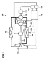
- a refrigeration cycle apparatus 100 of the present embodiment includes a first compressor 101 for compressing a refrigerant, a second compressor 102 provided in parallel with the first compressor 101 in a refrigerant circuit, a radiator 103 for cooling the refrigerant compressed by the first compressor 101 and the second compressor 102, an expander 104 for decompressing and expanding the refrigerant, and an evaporator 105 for heating the refrigerant expanded by the expander 104.
- These devices are connected by a pipe so as to form the refrigerant circuit.
- the refrigerant circuit branches off on a downstream side of the evaporator 105 so that the refrigerant is guided to each of the first compressor 101 and the second compressor 102.
- the branches of the refrigerant circuit are merged with each other on an upstream side of the radiator 103 so that the total amount of the compressed refrigerant flows into the radiator 103.
- the refrigerant circuit is filled with the refrigerant, such as carbon dioxide and hydrofluorocarbon.
- the radiator 103 is a water-refrigerant heat exchanger and the evaporator 105 is a fin tube heat exchanger.
- both of the radiator 103 and the evaporator 105 are fin tube heat exchangers.
- Each of the first compressor 101, the second compressor 102, and the expander 104 is composed of a positive displacement fluid machine of scroll type, rotary type, reciprocating type, or the like.
- the expander 104 recovers the energy released from the refrigerant during expansion in the form of power.
- the first compressor 101 and the expander 104 are connected to each other with a rotation shaft 123 so that the first compressor 101 uses the power recovered by the expander 104.
- a motor 110 for driving the rotation shaft 123 is disposed between the first compressor 101 and the expander 104.
- a rotation speed of the first compressor 101 always is equal to that of the expander 104 because they are coupled to each other with the rotation shaft 123.
- a dedicated motor 111 is connected to the second compressor 102.
- a rotation speed of the motor 110 can be controlled separately from that of the motor 111.
- the rotation speed of the first compressor 101 can be controlled independently from that of the second compressor 102. Thereby, the constraint of constant density ratio can be avoided.
- the first compressor 101, the motor 110, the rotation shaft 123, and the expander 104 are accommodated in a common closed casing (not shown).
- This type of fluid machine is disclosed in WO 2006/035934 , for example.
- the second compressor 102 and the motor 111 also are accommodated in a common closed casing (not shown).
- the refrigeration cycle apparatus 100 further includes a controller 112 as a means to control the operation, a first inverter 125 for feeding electric power to the motor 110, and a second inverter 127 for feeding electric power to the motor 111.
- a DSP Digital Signal Processor
- the controller 112 controls the rotation speeds of the motors 110 and 111, more specifically, the rotation speeds of the first compressor 101 and the second compressor 102 by controlling the inverters 125 and 127.
- the refrigerant circuit is provided with a first temperature sensor 106 for detecting a temperature of the refrigerant at an inlet of the first compressor 101, a second temperature sensor 107 for detecting a temperature of the refrigerant at an outlet of the first compressor 101, a third temperature sensor 108 for detecting a temperature of the refrigerant at an inlet of the expander 104, a fourth temperature sensor 109 for detecting a temperature of the refrigerant at an outlet of the expander 104, a frost formation temperature sensor 120 for detecting a surface temperature of a heat-transfer pipe in the evaporator 105, and an outside air temperature sensor 121 for detecting an outside air temperature around the evaporator 105.
- Temperature detecting elements such as a thermistor and a thermocouple, can be used for these temperature sensors. Signals from each of the temperature sensors are inputted to the controller 112.
- the first compressor 101 may have a design displacement different from that of the second compressor 102, it is advantageous when they are equal. This is because the cost can be reduced by using the same fluid machines for the first compressor 101 and the second compressor 102.
- the "displacement" means a containment volume at the time when the drawing of the refrigerant is completed.
- the "defrosting operation” means an unsteady operation for melting the frost and ice formed on the evaporator 105 by allowing the expander 104 to decompress the refrigerant compressed by the first compressor 101 and the second compressor 102 substantially without cooling the refrigerant, and then allowing the refrigerant to flow through the evaporator 105. Specifically, stopping a water pump in a water heater or a fan in an air conditioner, which turns the amount of the water or air flowing into the radiator 103 into zero, allows the refrigerant to flow into the expander 104 substantially without being cooled.
- Fig. 2 is a Mollier diagram of the refrigeration cycle apparatus of the present invention during the defrosting operation.
- the three cycles (defrosting cycles) shown in Fig. 2 illustrate schematically Cycle P1 at the time of starting the defrosting operation, Cycle P2 in the middle of the defrosting operation, and Cycle P3 at the time of ending the defrosting operation, respectively.
- the refrigerant is compressed by the compressors 101 and 102 from Point A1 to Point B1 and flows into the radiator 103. Since no heat exchange occurs in the radiator 103, Point B1 corresponds to the state of the refrigerant at the inlet of the expander 104. The refrigerant is decompressed by the expander 104 and moves to an inlet (Point C1) of the evaporator 105. Enthalpy difference ⁇ H between Point B1 and Point C1 corresponds to the power recovered by the expander 104.
- the refrigerant that has flowed into the evaporator 105 melts the frost by heating the evaporator 105, and then returns to the inlets (Point A1) of the compressors 101 and 102.
- Enthalpy difference ⁇ h between Point C1 and Point A1 corresponds to an amount of the heat given to the evaporator 105.
- the total of the flow rate of the refrigerant at the outlet of the first compressor 101 and the flow rate of the refrigerant at the outlet of the second compressor 102 is increased gradually in accordance with melting of the frost.
- the temperature of the refrigerant at each part of the refrigeration cycle apparatus 100 rises.
- the cycle shifts rightward in the Mollier diagram and both of the high pressure and the low pressure of the cycle rise (P1-P2-P3).
- the compressors 101 and 102 are driven at maximum rotation speeds from immediately after the start to the end of the defrosting operation, the density ratio of the refrigerant cannot be changed.
- shortage of the flow rate of the refrigerant to be displaced by the expander 104 gradually becomes noticeable, and the refrigeration cycle apparatus forcedly is operated in a cycle straying significantly from the ideal cycle.
- the phrase “increase a flow rate gradually” means that the flow rate may be increased continuously or stepwise.
- “increase a rotation speed gradually” means that the rotation speed may be increased continuously or stepwise.
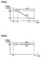
- Fig. 3 shows Pattern A in which the rotation speed of the first compressor 101 is increased gradually.
- Fig. 4 shows Pattern B in which the rotation speed of the second compressor 102 is increased gradually.
- Fig. 5 shows Pattern C in which the rotation speed of the second compressor 102 is decreased gradually, and
- Fig. 6 shows Pattern D in which the rotation speeds of the compressors 101 and 102 are maximum from the start to the end of the defrosting operation.
- Time R denotes the time at which the defrosting is started
- Time S and Time V denote the times at which the rotation speed of the first compressor 101 or the rotation speed of the second compressor 102 becomes constant
- Times Ta to Td denote the times at which the defrosting is ended
- Time U denotes the time at which the rotation speed of the second compressor 102 starts decreasing.
- Hz1 denotes the rotation speed of the first compressor 101
- Hz2 denotes the rotation speed of the second compressor 102.
- Rotation speed L denotes the design maximum rotation speed of each of the first compressor 101 and the second compressor 102.
- the rotation speed L is 70 Hz to 90 Hz, for example.
- Rotation speed M denotes a rated rotation speed of each of the first compressor 101 and the second compressor 102, or a rotation speed near the rated rotation speed.
- the rotation speed M is 50 Hz to 70 Hz, for example.
- Rotation speed N is a rotation speed lower than the rated rotation speed, and it is 20 Hz to 50 Hz, for example. Since there is a case where the second compressor 102 is stopped and only the first compressor 101 is operated immediately before the defrosting operation is started, the rotation speed N may be zero.
- the values of L, M, and N are determined in accordance with the specifications, applications, and use environment of the refrigeration cycle apparatus and are not limited to the above-mentioned ranges.
- the rotation speed of the first compressor 101 can be increased at a rate of 2 Hz/min to 20 Hz/min (or 4 Hz/min to 15 Hz/min), for example.
- the rotation speed of the second compressor 102 can be increased at a rate of 2 Hz/min to 20 Hz/min (or 4 Hz/min to 15 Hz/min.) By accelerating the compressor slowly at a rate of this level, it is possible to shorten certainly the defrosting time and reduce the power consumption.
- a control can be executed so that the temperature of the refrigerant at an outlet of the evaporator 105 is increased at a rate of 2°C /min to 4°C /min.
- the acceleration of the compressor may be continued from the start to the end of the defrosting operation by predicting the defrosting time, or the acceleration may be stopped on the way. That is, it is possible to increase the rotation speed at a somewhat low rate until reaching a predetermined rotation speed, and then maintain this predetermined rotation speed until the defrosting operation is ended.
- the first compressor 101 is accelerated from Time R (the start of the defrosting) to Time S, and the rotation speed of the first compressor 101 is kept at M from Time S to Time Ta (the end of the defrosting).
- the second compressor 102 is accelerated from Time R (the start of the defrosting) to Time S, and the rotation speed of the second compressor 102 is kept at M from Time S to Time Tb (the end of the defrosting). Furthermore, the rotation speeds of the compressors 101 and 102 may be increased monotonically (continuously) or stepwise.
- the refrigeration cycle apparatus (for a water heater) shown in Fig. 1 was produced and subject to the defrosting operation in each of the patterns, and measured for the time (defrosting time) and power consumption needed for defrosting.
- the evaporator 105 was placed in an environment at a temperature of 2°C, and the refrigeration cycle apparatus was operated at a rated rotation speed (60 Hz for the first compressor 101 and 60 Hz for the second compressor). Then, the defrosting operation was started 30 minutes after the surface temperature of the heat-transfer pipe provided in the evaporator 105 became -6°C. The point of time when the temperature of the refrigerant at the outlet of the evaporator 105 reached 10°C was defined as the end of the defrosting.
- the specific configuration of the refrigeration cycle apparatus is as follows.
- Table 1 shows the results.
- “defrosting time” and “power consumption” each are indicated with a relative ratio when the value in Pattern B is taken as 100.
- Time (R), (S), (T), (U), and (V) correspond to the times shown in Fig. 3 to Fig. 6 , respectively.
- the ratio of the density of the refrigerant at the inlet of the expander 104 to the density of the refrigerant at the inlet of the compressors 101 and 102 is increased.
- Pattern A is a control pattern in which the rotation speed of the second compressor 102 is kept at the maximum rotation speed L and the rotation speed of the first compressor 101 is increased gradually from the rotation speed N that is lower than the maximum rotation speed L after the defrosting operation is started.
- Pattern A because of the low rotation speed of the expander 104 at the time of starting the defrosting operation, the circulation amount of the refrigerant was reduced and the defrosting time became slightly longer. However, a certain effect was obtained also in Pattern A, although it was not so much as in Pattern B.
- Pattern B is a control pattern in which the rotation speed of the first compressor 101 is kept at the maximum rotation speed L and the rotation speed of the second compressor 102 is increased gradually from the rotation speed N that is lower than the maximum rotation speed L after the defrosting operation is started. Pattern B ended the defrosting in a shortest time and required the lowest power consumption. Reasons for this may be as follows. (i) Since the difference between the high pressure and the low pressure in the cycle relatively was small at the time of starting the defrosting, the enthalpy that the refrigerant lost in the expander 104 was also small. Thereby, the amount of heat ⁇ h for heating the evaporator 105 could be ensured sufficiently from the early stage of the defrosting. (ii) The rotation speed of the first compressor 101 was high from the starting of the defrosting, and the circulation amount of the refrigerant was able to be ensured sufficiently.
- Pattern C is a control pattern in which the rotation speed of the first compressor 101 is kept at the maximum rotation speed L and the rotation speed of the second compressor 102 is decreased gradually. Pattern C required the longest defrosting time. This may be because the low pressure of the cycle at the time of starting the defrosting was too low.
- Pattern D is a control pattern in which both of the rotation speed of the first compressor 101 and that of the second compressor 102 are kept at high rotation speeds. Pattern D required a longer defrosting time than those of the Patterns A and B, and also required the largest power consumption thereamong. This may be because the low pressure of the cycle at the time of starting the defrosting was too low, and Pattern D failed to cope with the variation in the state of the refrigeration cycle apparatus over time.
- Patterns A and B there also can be considered a control pattern in which the rotation speeds of the first compressor 101 and the second compressor 102 are increased gradually after the defrosting operation is started.
- This control pattern also is effective as long as it can ensure the flow rate of the refrigerant sufficiently.
- the flow rate of the refrigerant is increased gradually by increasing gradually the rotation speed of at least one selected from the first compressor 101 and the second compressor 102.
- the flow rate of the refrigerant is increased gradually by keeping the rotation speed of the first compressor 101 at the maximum rotation speed L and increasing the rotation speed of the second compressor 102 gradually from the rotation speed N that is lower than the rated rotation speed of the second compressor 102.
- Pattern B shown in Fig. 4 the rotation speed of the second compressor 102, which is Hz2, is represented by a function of time t, f(t) + N, where N denotes an initial rotation speed.
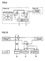
- the controller 112 executes the control shown in Fig. 7 in response to the establishment of conditions for starting the defrosting operation.
- the conditions for starting the defrosting operation are not particularly limited.
- the defrosting operation is started when the outside air temperature is equal to or lower than a predetermined temperature and a predetermined time has passed since the surface temperature of the heat-transfer pipe provided in the evaporator 105 became equal to or lower than a predetermined temperature that requires the defrosting.
- the defrosting operation is started when the temperature detected by the outside air temperature sensor 121 is 0°C to 5°C and the temperature detected by the frost formation temperature sensor 120 is -5°C to -2°C (or when a predetermined time has passed since then).
- Step 201 the rotation speed Hz1 of the first compressor 101 is set to L, and the rotation speed Hz2 of the second compressor 102 is set to f(t) + N.
- the maximum value of the rotation speed Hz2 of the second compressor 102 is denoted as M.
- L, M, and N are rotation speeds shown in Fig. 4 , respectively.
- Step 202 temperature Teout of the refrigerant at the outlet of the evaporator 105 is compared with preset value Tem (10°C, for example). If Teout > Tem, the controller 112 judges that the frost has been melted sufficiently and ends the defrosting operation. If Teout ⁇ Tem, the controller 112 judges that the defrosting is insufficient and returns to Step 201 to increase the rotation speed of the second compressor 102.
- Whether the evaporator 105 has been defrosted can be judged reliably based on the temperature Teout of the refrigerant at the outlet of the evaporator 105.
- the temperature Teout can be acquired from the first temperature sensor 106 because it approximately is equal to the temperature of the refrigerant at the inlet of the first compressor 101.
- An additional temperature sensor may be provided near the outlet of the evaporator 105.
- Step 301 the rotation speed Hz1 of the first compressor 101 is set to L and the rotation speed Hz2 of the second compressor 102 is set to f(t) + N. This is the same as in Step 201 shown in Fig. 7 .
- Step 302 a judgment is made whether the defrosting operation has been stabilized. Specifically, a judgment is made whether a predetermined time (5 minutes, for example) has passed since the defrosting was started. If the predetermined time has passed, the sequence proceeds to Step 303. If the predetermined time has not passed, it returns to Step 301.
- the acceleration of the second compressor 102 may be determined so that the rotation speed Hz2 of the second compressor 102 reaches the rotation speed M within this predetermined time.
- Step 303 temperature Td of the refrigerant at the inlet of the first compressor 101 (a suction temperature of the first compressor 101), temperature Ts of the refrigerant at the outlet of the first compressor 101 (a discharge temperature of the first compressor 101), temperature Tj of the refrigerant at the inlet of the expander 104, temperature Tk of the refrigerant at the outlet of the expander 104, the rotation speed Hz1 of the first compressor 101, and the rotation speed Hz2 of the second compressor 102 are detected.
- the temperatures Td, Ts, Tj, and Tk can be acquired from the first to fourth temperature sensors 106 to 109, respectively.
- the rotation speeds Hz1 and Hz2 are data that the controller 112 manages.
- Step 304 calculates the density ratio ( ⁇ e / ⁇ c ) of the refrigerant from the detected values mentioned above.
- the density ⁇ c is a density of the refrigerant at the inlet of the first compressor 101
- the density ⁇ e is a density of the refrigerant at the inlet of the expander 104.
- Target discharge temperature Tsm of the first compressor 101 is calculated by using a correlation equation, a numerical data table, etc. saved in the controller 112 in advance, based on the calculated density ratio ( ⁇ e / ⁇ c ).
- Step 305 actual discharge temperature Ts is compared with the target discharge temperature Tsm. If Ts > Tsm, the controller 112 judges that the high pressure of the cycle is too high. In this case, the refrigeration cycle tends to balance in such a manner that the density ⁇ e of the refrigerant at the inlet of the expander 104 is increased. Thus, the rotation speed of the second compressor 102 is decreased and the flow rate of the refrigerant at the inlet of the expander 104 is lowered in Step 306. Thereby, the discharge temperature Ts of the first compressor 101 and the high pressure of the cycle are decreased.
- the controller 112 judges that the high pressure of the cycle is too low. In this case, the refrigeration cycle tends to balance in such a manner that the density ⁇ e of the refrigerant at the inlet of the expander 104 is decreased. Thus, the rotation speed of the second compressor 102 is increased and the flow rate of the refrigerant at the inlet of the expander 104 is increased in Step 307. Thereby, the discharge temperature Ts of the first compressor 101 and the high pressure of the cycle are increased.
- Step 308 the temperature Teout of the refrigerant at the outlet of the evaporator 105 is compared with the preset value Tem (10°C, for example). In the present embodiment, the temperature Teout approximately is equal to the suction temperature Td of the first compressor 101. If Teout > Tem, the controller 112 judges that the frost has been melted sufficiently and ends the defrosting operation. If Teout ⁇ Tem, the controller 112 judges that the defrosting is insufficient and returns to Step 303.
- Tem 10°C, for example
- the rotation speed of the second compressor 102 is increased gradually during the period from when the defrosting operation is started until the predetermined time passes.
- the target discharge temperature Tsm of the first compressor 101 is calculated based on the density ratio ( ⁇ e / ⁇ c ), and the rotation speed of the second compressor 102 is controlled so that the actual discharge temperature Ts approaches the target discharge temperature Tsm.
- a higher COP can be achieved.
- the reliability of the refrigeration cycle apparatus 100 is increased.
- the circulation amount of the refrigerant is increased gradually by increasing the rotation speed of the first compressor 101 and/or the rotation speed of the second compressor 102 gradually.
- the circulation amount of the refrigerant can be increased gradually by performing a control for increasing the displacement gradually instead of increasing the rotation speed gradually.
- the same results are obtained also when the control for increasing the rotation speed and the control for increasing the displacement are performed in combination.
- the refrigeration cycle apparatus of the present invention is applicable to various applications, such as a water heater, an air conditioner, a floor heating system, a bathroom drier, and a snow melting system, in which frost may be formed on an evaporator thereof.
Landscapes
- Engineering & Computer Science (AREA)
- Physics & Mathematics (AREA)
- Mechanical Engineering (AREA)
- Thermal Sciences (AREA)
- General Engineering & Computer Science (AREA)
- Air Conditioning Control Device (AREA)
- Defrosting Systems (AREA)
- Air-Conditioning For Vehicles (AREA)
- Heat-Pump Type And Storage Water Heaters (AREA)
Claims (9)
- Kältekreislauf-Vorrichtung, Folgendes umfassend:einen ersten Verdrängungsverdichter;einen zweiten Verdrängungsverdichter, dessen Drehzahl unabhängig von einer Drehzahl des ersten Verdichters gesteuert werden kann, wobei der zweite Verdrängungsverdichter parallel zu dem ersten Verdichter in einem Kältemittelkreislauf eingerichtet ist;einen Kühler zum Kühlen eines Kältemittels, welches durch die ersten und zweiten Verdichter komprimiert wird;einen Verdrängungsexpander zum Zurückgewinnen von Strom während des Dekomprimierens des Kältemittels, welches durch den Kühler gekühlt wird;einen Verdampfer zum Verdampfen des Kältemittels, welches durch den Expander dekomprimiert wird;eine Rotationswelle, die den ersten Verdichter mit dem Expander verbindet, so dass der erste Verdichter den Strom nutzt, der von dem Expander zurück gewonnen wird; undein Steuergerät zum Ausführen einer Steuerung, dadurch gekennzeichnet, dass die Steuerung einen Schritt umfasst, die Summe einer Durchflussmenge des Kältemittels an einem Auslass des ersten Verdichters und einer Durchflussmenge des Kältemittels an einem Auslass des zweiten Verdichters zu erhöhen, während eines Abtaubetriebs, bei dem Eis, welches auf dem Verdampfer gebildet ist, geschmolzen wird, indem dem Kältemittel, welches eine hohe Temperatur aufweist, gestattet wird, durch den Verdampfer zu strömen, wobei die Summe der Durchflussmengen in Übereinstimmung mit dem Schmelzen des Eises erhöht wird.
- Kältekreislauf-Vorrichtung nach Anspruch 1, wobei die Durchflussmenge des Kältemittels erhöht wird durch das kontinuierliche oder schrittweise Erhöhen der Drehzahl von zumindest einem ausgewählten von dem ersten und dem zweiten Verdichter, nachdem die Abtauoperation begonnen hat.
- Kältekreislauf-Vorrichtung nach Anspruch 2, wobei die Drehzahl von zumindest einem ausgewählten von dem ersten Verdichter und dem zweiten Verdichter erhöht wird auf ein Tempo von 2 Hz/min bis 20 Hz/min, nachdem die Abtauoperation begonnen hat.
- Kältekreislauf-Vorrichtung nach Anspruch 2, wobei die Durchflussmenge des Kältemittels erhöht wird, indem die Drehzahl des ersten Verdichters bei Drehzahl L gehalten wird und die Drehzahl des zweiten Verdichters kontinuierlich oder schrittweise von der Drehzahl N, die geringer ist als die Drehzahl L, erhöht wird, nachdem die Abtauoperation begonnen hat.
- Kältekreislauf-Vorrichtung nach Anspruch 4, wobei die Drehzahl L eine maximale Drehzahl des ersten Verdichters darstellt.
- Kältekreislauf-Vorrichtung nach Anspruch 2, wobei die Durchflussmenge des Kältemittels erhöht wird, indem die Drehzahl des zweiten Verdichters bei Drehzahl L gehalten wird und die Drehzahl des ersten Verdichters kontinuierlich oder schrittweise von der Drehzahl N, die geringer ist als die Drehzahl L, erhöht wird, nachdem die Abtauoperation begonnen hat.
- Kältekreislauf-Vorrichtung nach Anspruch 6, wobei die Drehzahl L eine maximale Drehzahl des zweiten Verdichters darstellt.
- Kältekreislauf-Vorrichtung nach Anspruch 1, wobei das Steuergerät den Abtaubetrieb bei einem Zustand beendet, bei dem das Kältemittel an einem Auslass des Verdampfers eine Temperatur aufweist, die einen voreingestellten Wert überschreitet.
- Kältekreislauf-Vorrichtung nach Anspruch 4, ferner umfassend:einen ersten Temperatursensor zum Erfassen einer Temperatur des Kältemittels an einem Einlass des ersten Verdichters;einen zweiten Temperatursensor zum Erfassen einer Temperatur des Kältemittels an dem Auslass des ersten Verdichters;einen dritten Temperatursensor zum Erfassen einer Temperatur des Kältemittels an einem Einlass des Expanders; undeinen vierten Temperatursensor zum Erfassen einer Temperatur des Kältemittels an einem Auslass des Expanders, wobei:die Drehzahl des zweiten Verdichters kontinuierlich oder schrittweise erhöht wird während einer Periode vom Beginn des Abtaubetriebs bis zum Ende eines vorbestimmten Zeitraums; unddie Steuerung, die das Steuergerät ausführt, ferner einen Schritt umfasst, nachdem der vorbestimmte Zeitraum vergangen ist, des Berechnens einer Ziel-Auslasstemperatur für das Kältemittel an dem Auslass des ersten Verdichters, der sich im Abtaubetrieb befindet, basierend auf Erfassungsergebnissen von dem ersten Temperatursensor, dem zweiten Temperatursensor, dem dritten Temperatursensor und dem vierten Temperatursensor, und der Steuerung der Drehzahl des zweiten Verdichters, so dass sich die Temperatur, die von dem zweiten Temperatursensor erfasst wurde, der Ziel-Auslasstemperatur annähert.
Applications Claiming Priority (2)
| Application Number | Priority Date | Filing Date | Title |
|---|---|---|---|
| JP2007263081 | 2007-10-09 | ||
| PCT/JP2008/002846 WO2009047898A1 (ja) | 2007-10-09 | 2008-10-08 | 冷凍サイクル装置 |
Publications (3)
| Publication Number | Publication Date |
|---|---|
| EP2196751A1 EP2196751A1 (de) | 2010-06-16 |
| EP2196751A4 EP2196751A4 (de) | 2012-03-07 |
| EP2196751B1 true EP2196751B1 (de) | 2013-06-26 |
Family
ID=40549050
Family Applications (1)
| Application Number | Title | Priority Date | Filing Date |
|---|---|---|---|
| EP08837464.0A Not-in-force EP2196751B1 (de) | 2007-10-09 | 2008-10-08 | Kältekreislaufvorrichtung |
Country Status (4)
| Country | Link |
|---|---|
| US (1) | US8590326B2 (de) |
| EP (1) | EP2196751B1 (de) |
| JP (1) | JP5121844B2 (de) |
| WO (1) | WO2009047898A1 (de) |
Families Citing this family (21)
| Publication number | Priority date | Publication date | Assignee | Title |
|---|---|---|---|---|
| DE102008054935A1 (de) * | 2008-12-18 | 2010-06-24 | BSH Bosch und Siemens Hausgeräte GmbH | Kältegerät mit einer Abtauheizung |
| EP2442050A1 (de) * | 2009-06-12 | 2012-04-18 | Panasonic Corporation | Kältekreislaufvorrichtung |
| ES2646188T3 (es) * | 2010-03-25 | 2017-12-12 | Mitsubishi Electric Corporation | Aparato de ciclo de refrigeración y procedimiento de operación del mismo |
| US10274210B2 (en) | 2010-08-27 | 2019-04-30 | Nortek Air Solutions Canada, Inc. | Heat pump humidifier and dehumidifier system and method |
| US9291377B2 (en) | 2011-05-20 | 2016-03-22 | Richard J. Cathriner | Air conditioning system with discharged heat driving compression of system refrigerant |
| US20130094972A1 (en) * | 2011-10-18 | 2013-04-18 | Ford Global Technologies, Llc | Climate Thermal Load Based Minimum Flow Rate Water Pump Control |
| KR101904870B1 (ko) * | 2012-01-30 | 2018-10-08 | 엘지전자 주식회사 | 압축기 제어 장치와 방법, 및 이를 포함한 냉장고 |
| JP5897994B2 (ja) * | 2012-06-06 | 2016-04-06 | シャープ株式会社 | 空気調和機 |
| US9772124B2 (en) | 2013-03-13 | 2017-09-26 | Nortek Air Solutions Canada, Inc. | Heat pump defrosting system and method |
| JP5549771B1 (ja) * | 2013-09-12 | 2014-07-16 | 株式会社富士通ゼネラル | 空気調和装置 |
| US10823482B2 (en) * | 2014-11-24 | 2020-11-03 | Carrier Corporation | Systems and methods for free and positive defrost |
| US10634414B2 (en) * | 2016-01-04 | 2020-04-28 | Haier Us Appliance Solutions, Inc. | Method for operating a fan within a refrigerator appliance |
| US10471793B2 (en) | 2016-10-12 | 2019-11-12 | Ford Global Technologies, Llc | Seat mounts for side load spring on a twist beam axle |
| JP2018091536A (ja) * | 2016-12-01 | 2018-06-14 | 株式会社デンソー | 冷凍サイクル装置 |
| WO2019003306A1 (ja) * | 2017-06-27 | 2019-01-03 | 三菱電機株式会社 | 空気調和装置 |
| US10914503B2 (en) * | 2018-02-01 | 2021-02-09 | Johnson Controls Technology Company | Coil heating systems for heat pump systems |
| US11131497B2 (en) * | 2019-06-18 | 2021-09-28 | Honeywell International Inc. | Method and system for controlling the defrost cycle of a vapor compression system for increased energy efficiency |
| DE102020107006B4 (de) * | 2020-03-13 | 2025-12-18 | Volkswagen Aktiengesellschaft | Verfahren zum Betreiben einer Wärmepumpe eines Kraftfahrzeuges und Wärmepumpe |
| JP2022087598A (ja) * | 2020-12-01 | 2022-06-13 | 株式会社前川製作所 | 冷凍機及び冷凍機の予冷時の運転方法 |
| CN114322133B (zh) * | 2021-12-14 | 2024-12-27 | 珠海格力电器股份有限公司 | 空调系统 |
| US11906188B2 (en) | 2022-03-11 | 2024-02-20 | Johnson Controls Tyco IP Holdings LLP | Energy efficient heat pump systems and methods |
Family Cites Families (24)
| Publication number | Priority date | Publication date | Assignee | Title |
|---|---|---|---|---|
| US2519010A (en) * | 1947-08-02 | 1950-08-15 | Philco Corp | Refrigeration system and method |
| US2494120A (en) * | 1947-09-23 | 1950-01-10 | Phillips Petroleum Co | Expansion refrigeration system and method |
| US2737031A (en) * | 1952-02-12 | 1956-03-06 | William A Wulle | Heat energy-converting system and process |
| US3277658A (en) * | 1965-07-19 | 1966-10-11 | Carrier Corp | Refrigeration apparatus |
| US3932159A (en) * | 1973-12-07 | 1976-01-13 | Enserch Corporation | Refrigerant expander compressor |
| US3986852A (en) * | 1975-04-07 | 1976-10-19 | E. I. Du Pont De Nemours And Company | Rotary cooling and heating apparatus |
| FR2349799A1 (fr) * | 1976-04-28 | 1977-11-25 | Abg Semca | Procede et dispositif de conditionnement de l'air d'une enceinte |
| DE3676191D1 (de) * | 1986-03-25 | 1991-01-24 | Mitsui Shipbuilding Eng | Waermepumpe. |
| US5428966A (en) * | 1988-01-21 | 1995-07-04 | Alsenz; Richard H. | Refrigeration system utilizing an expansion device in the evaporator |
| US4923492A (en) * | 1989-05-22 | 1990-05-08 | Hewitt J Paul | Closed system refrigeration using a turboexpander |
| JPH04340062A (ja) * | 1991-05-14 | 1992-11-26 | Nippondenso Co Ltd | 冷凍サイクル |
| US5467613A (en) * | 1994-04-05 | 1995-11-21 | Carrier Corporation | Two phase flow turbine |
| JP2001116371A (ja) | 1999-10-20 | 2001-04-27 | Daikin Ind Ltd | 空気調和装置 |
| JP2002081714A (ja) * | 2000-09-08 | 2002-03-22 | Daikin Ind Ltd | 空気調和機 |
| US6523358B2 (en) * | 2001-03-30 | 2003-02-25 | White Consolidated Industries, Inc. | Adaptive defrost control device and method |
| US6634180B2 (en) * | 2001-12-05 | 2003-10-21 | Carrier Corporation | System and method for defrost termination feedback |
| JP2003222391A (ja) | 2002-01-29 | 2003-08-08 | Daikin Ind Ltd | ヒートポンプ式給湯機 |
| JP3952951B2 (ja) * | 2003-01-08 | 2007-08-01 | ダイキン工業株式会社 | 冷凍装置 |
| JP3894190B2 (ja) | 2003-11-19 | 2007-03-14 | 松下電器産業株式会社 | ヒートポンプ給湯装置 |
| JP4617811B2 (ja) | 2004-09-30 | 2011-01-26 | ダイキン工業株式会社 | 流体機械 |
| JP2006242491A (ja) * | 2005-03-04 | 2006-09-14 | Mitsubishi Electric Corp | 冷凍サイクル装置 |
| JP4457928B2 (ja) * | 2005-03-15 | 2010-04-28 | ダイキン工業株式会社 | 冷凍装置 |
| JP2006258331A (ja) * | 2005-03-15 | 2006-09-28 | Daikin Ind Ltd | 冷凍装置 |
| EP1950881A1 (de) * | 2005-10-26 | 2008-07-30 | Matsushita Electric Industrial Co., Ltd. | Wärmepumpenanwendungsvorrichtung mit expansionseinrichtung |
-
2008
- 2008-10-08 EP EP08837464.0A patent/EP2196751B1/de not_active Not-in-force
- 2008-10-08 JP JP2009536922A patent/JP5121844B2/ja not_active Expired - Fee Related
- 2008-10-08 WO PCT/JP2008/002846 patent/WO2009047898A1/ja not_active Ceased
- 2008-10-08 US US12/680,780 patent/US8590326B2/en not_active Expired - Fee Related
Also Published As
| Publication number | Publication date |
|---|---|
| US8590326B2 (en) | 2013-11-26 |
| WO2009047898A1 (ja) | 2009-04-16 |
| US20100218528A1 (en) | 2010-09-02 |
| JP5121844B2 (ja) | 2013-01-16 |
| EP2196751A4 (de) | 2012-03-07 |
| EP2196751A1 (de) | 2010-06-16 |
| JPWO2009047898A1 (ja) | 2011-02-17 |
Similar Documents
| Publication | Publication Date | Title |
|---|---|---|
| EP2196751B1 (de) | Kältekreislaufvorrichtung | |
| EP1655558B1 (de) | Verfahren zur Regelung eines Kühlgerätes und Kühlgerät dafür | |
| EP2102569B1 (de) | Verfahren und systeme zur steuerung einer im freikühlmodus arbeitenden klimaanlage | |
| JP6580149B2 (ja) | 冷凍サイクル装置 | |
| JP6071648B2 (ja) | 空気調和装置 | |
| US20100313586A1 (en) | Refrigeration cycle apparatus | |
| US20110283723A1 (en) | Refrigeration cycle apparatus | |
| JP5343618B2 (ja) | 冷凍サイクル装置 | |
| EP2244037A1 (de) | Kältekreislaufvorrichtung | |
| JP2011144960A (ja) | 空気調和機および空気調和機の除霜運転方法 | |
| WO2006120922A1 (ja) | 冷凍サイクル装置 | |
| JP4258944B2 (ja) | 超臨界蒸気圧縮機式冷凍サイクル | |
| JP5320382B2 (ja) | 空気冷媒式冷凍装置のデフロスト方法及び装置 | |
| JP2010038463A (ja) | 冷凍サイクル装置 | |
| JP6086236B2 (ja) | 冷凍装置の圧縮機の容量制御方法および容量制御装置 | |
| JP5701084B2 (ja) | 加温システム | |
| JP4665736B2 (ja) | 冷凍サイクル装置の制御方法およびそれを用いた冷凍サイクル装置 | |
| JP5593623B2 (ja) | 冷凍装置 | |
| JP6467276B2 (ja) | 複合熱源ヒートポンプ装置 | |
| JP4715650B2 (ja) | 冷凍サイクル装置 | |
| JP2007147211A5 (de) | ||
| JP2022077246A (ja) | 採熱システム | |
| KR100436606B1 (ko) | 지열용 냉난방 최적시스템의 제어방법 | |
| JP4258219B2 (ja) | 冷凍サイクル装置 | |
| JP2013217563A (ja) | ヒートポンプ式液体加熱装置およびヒートポンプ式給湯機 |
Legal Events
| Date | Code | Title | Description |
|---|---|---|---|
| PUAI | Public reference made under article 153(3) epc to a published international application that has entered the european phase |
Free format text: ORIGINAL CODE: 0009012 |
|
| 17P | Request for examination filed |
Effective date: 20100510 |
|
| AK | Designated contracting states |
Kind code of ref document: A1 Designated state(s): AT BE BG CH CY CZ DE DK EE ES FI FR GB GR HR HU IE IS IT LI LT LU LV MC MT NL NO PL PT RO SE SI SK TR |
|
| AX | Request for extension of the european patent |
Extension state: AL BA MK RS |
|
| DAX | Request for extension of the european patent (deleted) | ||
| A4 | Supplementary search report drawn up and despatched |
Effective date: 20120208 |
|
| RIC1 | Information provided on ipc code assigned before grant |
Ipc: F25B 1/00 20060101ALI20120203BHEP Ipc: F25B 47/02 20060101AFI20120203BHEP Ipc: F25B 11/02 20060101ALI20120203BHEP |
|
| GRAP | Despatch of communication of intention to grant a patent |
Free format text: ORIGINAL CODE: EPIDOSNIGR1 |
|
| GRAP | Despatch of communication of intention to grant a patent |
Free format text: ORIGINAL CODE: EPIDOSNIGR1 |
|
| RIN1 | Information on inventor provided before grant (corrected) |
Inventor name: HONMA, MASAYA Inventor name: YAKUMARU, YUICHI Inventor name: TANIGUCHI, KATSUJI |
|
| GRAS | Grant fee paid |
Free format text: ORIGINAL CODE: EPIDOSNIGR3 |
|
| GRAA | (expected) grant |
Free format text: ORIGINAL CODE: 0009210 |
|
| AK | Designated contracting states |
Kind code of ref document: B1 Designated state(s): AT BE BG CH CY CZ DE DK EE ES FI FR GB GR HR HU IE IS IT LI LT LU LV MC MT NL NO PL PT RO SE SI SK TR |
|
| REG | Reference to a national code |
Ref country code: GB Ref legal event code: FG4D |
|
| REG | Reference to a national code |
Ref country code: CH Ref legal event code: EP |
|
| REG | Reference to a national code |
Ref country code: AT Ref legal event code: REF Ref document number: 618869 Country of ref document: AT Kind code of ref document: T Effective date: 20130715 |
|
| REG | Reference to a national code |
Ref country code: IE Ref legal event code: FG4D |
|
| REG | Reference to a national code |
Ref country code: DE Ref legal event code: R096 Ref document number: 602008025623 Country of ref document: DE Effective date: 20130822 |
|
| PG25 | Lapsed in a contracting state [announced via postgrant information from national office to epo] |
Ref country code: SE Free format text: LAPSE BECAUSE OF FAILURE TO SUBMIT A TRANSLATION OF THE DESCRIPTION OR TO PAY THE FEE WITHIN THE PRESCRIBED TIME-LIMIT Effective date: 20130626 Ref country code: FI Free format text: LAPSE BECAUSE OF FAILURE TO SUBMIT A TRANSLATION OF THE DESCRIPTION OR TO PAY THE FEE WITHIN THE PRESCRIBED TIME-LIMIT Effective date: 20130626 Ref country code: SI Free format text: LAPSE BECAUSE OF FAILURE TO SUBMIT A TRANSLATION OF THE DESCRIPTION OR TO PAY THE FEE WITHIN THE PRESCRIBED TIME-LIMIT Effective date: 20130626 Ref country code: GR Free format text: LAPSE BECAUSE OF FAILURE TO SUBMIT A TRANSLATION OF THE DESCRIPTION OR TO PAY THE FEE WITHIN THE PRESCRIBED TIME-LIMIT Effective date: 20130927 Ref country code: NO Free format text: LAPSE BECAUSE OF FAILURE TO SUBMIT A TRANSLATION OF THE DESCRIPTION OR TO PAY THE FEE WITHIN THE PRESCRIBED TIME-LIMIT Effective date: 20130926 Ref country code: LT Free format text: LAPSE BECAUSE OF FAILURE TO SUBMIT A TRANSLATION OF THE DESCRIPTION OR TO PAY THE FEE WITHIN THE PRESCRIBED TIME-LIMIT Effective date: 20130626 |
|
| REG | Reference to a national code |
Ref country code: AT Ref legal event code: MK05 Ref document number: 618869 Country of ref document: AT Kind code of ref document: T Effective date: 20130626 |
|
| REG | Reference to a national code |
Ref country code: LT Ref legal event code: MG4D |
|
| PG25 | Lapsed in a contracting state [announced via postgrant information from national office to epo] |
Ref country code: BG Free format text: LAPSE BECAUSE OF FAILURE TO SUBMIT A TRANSLATION OF THE DESCRIPTION OR TO PAY THE FEE WITHIN THE PRESCRIBED TIME-LIMIT Effective date: 20130926 Ref country code: HR Free format text: LAPSE BECAUSE OF FAILURE TO SUBMIT A TRANSLATION OF THE DESCRIPTION OR TO PAY THE FEE WITHIN THE PRESCRIBED TIME-LIMIT Effective date: 20130626 |
|
| REG | Reference to a national code |
Ref country code: NL Ref legal event code: VDEP Effective date: 20130626 |
|
| PG25 | Lapsed in a contracting state [announced via postgrant information from national office to epo] |
Ref country code: LV Free format text: LAPSE BECAUSE OF FAILURE TO SUBMIT A TRANSLATION OF THE DESCRIPTION OR TO PAY THE FEE WITHIN THE PRESCRIBED TIME-LIMIT Effective date: 20130626 |
|
| PG25 | Lapsed in a contracting state [announced via postgrant information from national office to epo] |
Ref country code: BE Free format text: LAPSE BECAUSE OF FAILURE TO SUBMIT A TRANSLATION OF THE DESCRIPTION OR TO PAY THE FEE WITHIN THE PRESCRIBED TIME-LIMIT Effective date: 20130626 Ref country code: SK Free format text: LAPSE BECAUSE OF FAILURE TO SUBMIT A TRANSLATION OF THE DESCRIPTION OR TO PAY THE FEE WITHIN THE PRESCRIBED TIME-LIMIT Effective date: 20130626 Ref country code: EE Free format text: LAPSE BECAUSE OF FAILURE TO SUBMIT A TRANSLATION OF THE DESCRIPTION OR TO PAY THE FEE WITHIN THE PRESCRIBED TIME-LIMIT Effective date: 20130626 Ref country code: PT Free format text: LAPSE BECAUSE OF FAILURE TO SUBMIT A TRANSLATION OF THE DESCRIPTION OR TO PAY THE FEE WITHIN THE PRESCRIBED TIME-LIMIT Effective date: 20131028 Ref country code: CY Free format text: LAPSE BECAUSE OF FAILURE TO SUBMIT A TRANSLATION OF THE DESCRIPTION OR TO PAY THE FEE WITHIN THE PRESCRIBED TIME-LIMIT Effective date: 20130828 Ref country code: IS Free format text: LAPSE BECAUSE OF FAILURE TO SUBMIT A TRANSLATION OF THE DESCRIPTION OR TO PAY THE FEE WITHIN THE PRESCRIBED TIME-LIMIT Effective date: 20131026 Ref country code: AT Free format text: LAPSE BECAUSE OF FAILURE TO SUBMIT A TRANSLATION OF THE DESCRIPTION OR TO PAY THE FEE WITHIN THE PRESCRIBED TIME-LIMIT Effective date: 20130626 Ref country code: CZ Free format text: LAPSE BECAUSE OF FAILURE TO SUBMIT A TRANSLATION OF THE DESCRIPTION OR TO PAY THE FEE WITHIN THE PRESCRIBED TIME-LIMIT Effective date: 20130626 |
|
| PGFP | Annual fee paid to national office [announced via postgrant information from national office to epo] |
Ref country code: DE Payment date: 20131021 Year of fee payment: 6 |
|
| PG25 | Lapsed in a contracting state [announced via postgrant information from national office to epo] |
Ref country code: NL Free format text: LAPSE BECAUSE OF FAILURE TO SUBMIT A TRANSLATION OF THE DESCRIPTION OR TO PAY THE FEE WITHIN THE PRESCRIBED TIME-LIMIT Effective date: 20130626 Ref country code: RO Free format text: LAPSE BECAUSE OF FAILURE TO SUBMIT A TRANSLATION OF THE DESCRIPTION OR TO PAY THE FEE WITHIN THE PRESCRIBED TIME-LIMIT Effective date: 20130626 Ref country code: ES Free format text: LAPSE BECAUSE OF FAILURE TO SUBMIT A TRANSLATION OF THE DESCRIPTION OR TO PAY THE FEE WITHIN THE PRESCRIBED TIME-LIMIT Effective date: 20131007 Ref country code: PL Free format text: LAPSE BECAUSE OF FAILURE TO SUBMIT A TRANSLATION OF THE DESCRIPTION OR TO PAY THE FEE WITHIN THE PRESCRIBED TIME-LIMIT Effective date: 20130626 |
|
| PG25 | Lapsed in a contracting state [announced via postgrant information from national office to epo] |
Ref country code: CY Free format text: LAPSE BECAUSE OF FAILURE TO SUBMIT A TRANSLATION OF THE DESCRIPTION OR TO PAY THE FEE WITHIN THE PRESCRIBED TIME-LIMIT Effective date: 20130626 |
|
| PG25 | Lapsed in a contracting state [announced via postgrant information from national office to epo] |
Ref country code: DK Free format text: LAPSE BECAUSE OF FAILURE TO SUBMIT A TRANSLATION OF THE DESCRIPTION OR TO PAY THE FEE WITHIN THE PRESCRIBED TIME-LIMIT Effective date: 20130626 |
|
| PLBE | No opposition filed within time limit |
Free format text: ORIGINAL CODE: 0009261 |
|
| STAA | Information on the status of an ep patent application or granted ep patent |
Free format text: STATUS: NO OPPOSITION FILED WITHIN TIME LIMIT |
|
| PG25 | Lapsed in a contracting state [announced via postgrant information from national office to epo] |
Ref country code: IT Free format text: LAPSE BECAUSE OF FAILURE TO SUBMIT A TRANSLATION OF THE DESCRIPTION OR TO PAY THE FEE WITHIN THE PRESCRIBED TIME-LIMIT Effective date: 20130626 Ref country code: MC Free format text: LAPSE BECAUSE OF FAILURE TO SUBMIT A TRANSLATION OF THE DESCRIPTION OR TO PAY THE FEE WITHIN THE PRESCRIBED TIME-LIMIT Effective date: 20130626 |
|
| REG | Reference to a national code |
Ref country code: CH Ref legal event code: PL |
|
| 26N | No opposition filed |
Effective date: 20140327 |
|
| GBPC | Gb: european patent ceased through non-payment of renewal fee |
Effective date: 20131008 |
|
| REG | Reference to a national code |
Ref country code: DE Ref legal event code: R097 Ref document number: 602008025623 Country of ref document: DE Effective date: 20140327 |
|
| REG | Reference to a national code |
Ref country code: IE Ref legal event code: MM4A |
|
| PG25 | Lapsed in a contracting state [announced via postgrant information from national office to epo] |
Ref country code: GB Free format text: LAPSE BECAUSE OF NON-PAYMENT OF DUE FEES Effective date: 20131008 Ref country code: CH Free format text: LAPSE BECAUSE OF NON-PAYMENT OF DUE FEES Effective date: 20131031 Ref country code: LI Free format text: LAPSE BECAUSE OF NON-PAYMENT OF DUE FEES Effective date: 20131031 |
|
| REG | Reference to a national code |
Ref country code: FR Ref legal event code: ST Effective date: 20140630 |
|
| PG25 | Lapsed in a contracting state [announced via postgrant information from national office to epo] |
Ref country code: FR Free format text: LAPSE BECAUSE OF NON-PAYMENT OF DUE FEES Effective date: 20131031 |
|
| PG25 | Lapsed in a contracting state [announced via postgrant information from national office to epo] |
Ref country code: IE Free format text: LAPSE BECAUSE OF NON-PAYMENT OF DUE FEES Effective date: 20131008 |
|
| REG | Reference to a national code |
Ref country code: DE Ref legal event code: R119 Ref document number: 602008025623 Country of ref document: DE |
|
| PG25 | Lapsed in a contracting state [announced via postgrant information from national office to epo] |
Ref country code: TR Free format text: LAPSE BECAUSE OF FAILURE TO SUBMIT A TRANSLATION OF THE DESCRIPTION OR TO PAY THE FEE WITHIN THE PRESCRIBED TIME-LIMIT Effective date: 20130626 |
|
| PG25 | Lapsed in a contracting state [announced via postgrant information from national office to epo] |
Ref country code: HU Free format text: LAPSE BECAUSE OF FAILURE TO SUBMIT A TRANSLATION OF THE DESCRIPTION OR TO PAY THE FEE WITHIN THE PRESCRIBED TIME-LIMIT; INVALID AB INITIO Effective date: 20081008 Ref country code: DE Free format text: LAPSE BECAUSE OF NON-PAYMENT OF DUE FEES Effective date: 20150501 Ref country code: LU Free format text: LAPSE BECAUSE OF NON-PAYMENT OF DUE FEES Effective date: 20131008 |
|
| PG25 | Lapsed in a contracting state [announced via postgrant information from national office to epo] |
Ref country code: MT Free format text: LAPSE BECAUSE OF FAILURE TO SUBMIT A TRANSLATION OF THE DESCRIPTION OR TO PAY THE FEE WITHIN THE PRESCRIBED TIME-LIMIT Effective date: 20130626 |